EP3594440B1 - Schirmsystem und gebäude - Google Patents
Schirmsystem und gebäude Download PDFInfo
- Publication number
- EP3594440B1 EP3594440B1 EP19185030.4A EP19185030A EP3594440B1 EP 3594440 B1 EP3594440 B1 EP 3594440B1 EP 19185030 A EP19185030 A EP 19185030A EP 3594440 B1 EP3594440 B1 EP 3594440B1
- Authority
- EP
- European Patent Office
- Prior art keywords
- screen
- pulling cable
- torsion tube
- screen system
- movable pulling
- Prior art date
- Legal status (The legal status is an assumption and is not a legal conclusion. Google has not performed a legal analysis and makes no representation as to the accuracy of the status listed.)
- Active
Links
Images


Classifications
-
- E—FIXED CONSTRUCTIONS
- E06—DOORS, WINDOWS, SHUTTERS, OR ROLLER BLINDS IN GENERAL; LADDERS
- E06B—FIXED OR MOVABLE CLOSURES FOR OPENINGS IN BUILDINGS, VEHICLES, FENCES OR LIKE ENCLOSURES IN GENERAL, e.g. DOORS, WINDOWS, BLINDS, GATES
- E06B9/00—Screening or protective devices for wall or similar openings, with or without operating or securing mechanisms; Closures of similar construction
- E06B9/24—Screens or other constructions affording protection against light, especially against sunshine; Similar screens for privacy or appearance; Slat blinds
- E06B9/40—Roller blinds
-
- A—HUMAN NECESSITIES
- A01—AGRICULTURE; FORESTRY; ANIMAL HUSBANDRY; HUNTING; TRAPPING; FISHING
- A01G—HORTICULTURE; CULTIVATION OF VEGETABLES, FLOWERS, RICE, FRUIT, VINES, HOPS OR SEAWEED; FORESTRY; WATERING
- A01G9/00—Cultivation in receptacles, forcing-frames or greenhouses; Edging for beds, lawn or the like
- A01G9/22—Shades or blinds for greenhouses, or the like
- A01G9/227—Shades or blinds for greenhouses, or the like rolled up during non-use
-
- E—FIXED CONSTRUCTIONS
- E06—DOORS, WINDOWS, SHUTTERS, OR ROLLER BLINDS IN GENERAL; LADDERS
- E06B—FIXED OR MOVABLE CLOSURES FOR OPENINGS IN BUILDINGS, VEHICLES, FENCES OR LIKE ENCLOSURES IN GENERAL, e.g. DOORS, WINDOWS, BLINDS, GATES
- E06B9/00—Screening or protective devices for wall or similar openings, with or without operating or securing mechanisms; Closures of similar construction
- E06B9/24—Screens or other constructions affording protection against light, especially against sunshine; Similar screens for privacy or appearance; Slat blinds
- E06B2009/2423—Combinations of at least two screens
- E06B2009/2447—Parallel screens
- E06B2009/2458—Parallel screens moving simultaneously
-
- E—FIXED CONSTRUCTIONS
- E06—DOORS, WINDOWS, SHUTTERS, OR ROLLER BLINDS IN GENERAL; LADDERS
- E06B—FIXED OR MOVABLE CLOSURES FOR OPENINGS IN BUILDINGS, VEHICLES, FENCES OR LIKE ENCLOSURES IN GENERAL, e.g. DOORS, WINDOWS, BLINDS, GATES
- E06B9/00—Screening or protective devices for wall or similar openings, with or without operating or securing mechanisms; Closures of similar construction
- E06B9/24—Screens or other constructions affording protection against light, especially against sunshine; Similar screens for privacy or appearance; Slat blinds
- E06B9/40—Roller blinds
- E06B2009/405—Two rollers
-
- Y—GENERAL TAGGING OF NEW TECHNOLOGICAL DEVELOPMENTS; GENERAL TAGGING OF CROSS-SECTIONAL TECHNOLOGIES SPANNING OVER SEVERAL SECTIONS OF THE IPC; TECHNICAL SUBJECTS COVERED BY FORMER USPC CROSS-REFERENCE ART COLLECTIONS [XRACs] AND DIGESTS
- Y02—TECHNOLOGIES OR APPLICATIONS FOR MITIGATION OR ADAPTATION AGAINST CLIMATE CHANGE
- Y02A—TECHNOLOGIES FOR ADAPTATION TO CLIMATE CHANGE
- Y02A40/00—Adaptation technologies in agriculture, forestry, livestock or agroalimentary production
- Y02A40/10—Adaptation technologies in agriculture, forestry, livestock or agroalimentary production in agriculture
- Y02A40/25—Greenhouse technology, e.g. cooling systems therefor
Definitions
- the present invention relates to a screen system. Furthermore, the invention relates to a building provided with such a screen system.
- the screen system is suitable for shielding, for example, light and/or heat. More specifically, the invention relates to a screen system intended for greenhouse horticulture.
- the invention also pertains to a building used for greenhouse horticulture, as well as a greenhouse in which the screen system is installed.
- each tension roller comprises a tension spring, and the tension rollers are interconnected by screen cloth parts.
- the tension springs in the tension rollers are biased such that the screen tends to assume a rolled-in condition and is extendible against the bias of the tension springs.
- DE 3728913 A1 is for a broad web awning, in which the awning cloth is divided up into part-webs and in each case two part-webs or part-web portions are assigned to a particular cloth roller, which for their part are capable of travelling in longitudinal rails.
- the sunshade assembly disclosed in DE 20 2006 004615 U1 , which has at least one shade canopy supported on the ground by three spaced vertical rods and a canopy winding roller rotating between two rods. The free ends of the canopies are secured to other rods.
- the winding shaft is powered by a motor with an external control and control buttons and also a remote control.
- the assembly is fitted with a wind and light sensor.
- the document discloses a method for unwinding/winding a laminar sheet arranged so as to cover an area and forming part of a winding structure, which comprises a supporting structure associated with the area and including a cylinder for supporting said laminar sheet that identifies a first longitudinal axis of rotation, drive means for rotating the cylinder around the first longitudinal axis and elastic means cooperating mechanically with the drive means during the unwinding/winding of the laminar sheet.
- the unwinding of the laminar sheet from the cylinder is due to the effect of the rotation of the cylinder induced by the drive means, while the winding of the laminar sheet onto the cylinder is due to the effect of the recovery of the mechanical energy stored by the elastic means during the unwinding of the laminar sheet.
- screen systems that are known from the most recent technology include a variety of screens characterized by the properties that contribute to the aforementioned goal, namely the percentage of heat they allow to pass through and the amount of heat they shield.
- the screen systems also include a variety of cables that are used to move the screens and/or keep them in place.
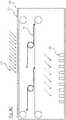
- Figure 1 shows an installation based on the most recent technology.
- the system consists of a screen 1 attached on one side to a stationary point 5, for example a beam or lattice or other kind of stationary part of a building, and on the other side to a screen 2.
- Carrier 2 can be moved vis-à-vis a stationary support cable 3, on which screen 1 rests.
- the surface of screen 1 can be adjusted by setting in motion a pulling cable 4, which runs under support cable 3, and which is attached to carrier 2.
- the familiar system includes a motor for moving pulling cable 4 and a control unit for controlling the motor for the complete unfolding or complete retraction of screen 1.
- One of the aims of the present invention is to provide a screen system in which the above-mentioned disadvantages do not or hardly occur.
- the screen system as defined in accompanying claim 1, wherein it comprises a control unit equipped to control the first motor and the second motor independently of each other, and configured to control the first and second motors such that the screen system is operational in at least two of the following three operating modes: an effective length of the screen remains constant, whereas the screen moves translationally, the effective length of the screen varies, whereas the screen does not move translationally, or the effective length of the screen varies, and the screen moves translationally.
- an effective length of the screen remains constant, whereas the screen moves translationally, the effective length of the screen varies, whereas the screen does not move translationally, or the effective length of the screen varies, and the screen moves translationally.
- the light can be shielded more evenly and as required. Because the position of the sun changes during the day, a moving screen can be used to compensate for this change. However, if the light distribution is homogenous, it is still possible to control the effective screen over time by moving the screen, which has been at least partially opened.
- the screen may comprise a first screen part and a second screen part connected to each other by means of a torsion tube, wherein the torsion tube is configured to rotate so as to roll the first and second screen parts onto the torsion tube and to keep it taut.
- the first screen part and the second screen part can be rolled up simultaneously and on top of each other. This makes it possible that, despite the separation of the screen, a single roll-up location and roll-up movement are sufficient to roll up the screen.
- the screen system can include a torsion spring for placing the rotating movement of the torsion tube under spring tension. When using a torsion spring, the torsion tube does not require an electrical connection as would be necessary if an internal motor were used.
- a first end of the torsion spring can be connected to the torsion tube and a second end of the torsion spring can be connected to a rotation-fixed second attachment point. This attachment as well as the orientation of the torsion spring determines the direction of rotation in which the torsion tube will rotate.
- the rotation-fixed second attachment point includes a fixed guide member in relation to which or into which the second end of the torsion spring can only move translationally. This movement of the torsion tube allows the torsion tube to move with the enlargement and/or reduction of the effective surface area of the screen.
- the first screen part is connected at a first end thereof to the first attachment point and is connected at a second end thereof to the torsion tube.
- the second screen part is connected at a first end to the torsion tube and at a second end to a first movable pulling cable.
- the first screen part is wrapped around the torsion tube at a side of the torsion tube facing away from the first movable pulling cable and the second screen part is wrapped around the torsion tube at a side of the torsion tube facing towards the first movable pulling cable.
- the first screen part is held above the pulling cable moving underneath the screen part.
- the second screen part can be directly supported by the pulling cable that moves with this screen part. Because the second screen part does not move much, if at all, compared to the first movable pulling cable, there is little or no wear as a result of friction.
- the first movable pulling cable can be set in motion by the first motor that is controlled by the control unit. With this first motor and control unit, the effective surface area of the screen can be increased or decreased with the result that the plants in the greenhouse can be shielded as needed.
- the screen system also includes a second movable pulling cable, with the first attachment point connected to the second movable pulling cable.
- the function of this second pulling cable is that the first attachment point can be set in motion.
- a second motor is used to set in motion the second movable pulling cable and thus the first attachment point, which is also controlled by the control unit.
- a further function of the second movable pulling cable is to prevent the screen parts from blowing upwards as a result of air flow, such as, the wind when the greenhouse is partially open.
- the screen is attached on one side to a stationary point. This means that in the immediate vicinity of this point there is always a shadow on the plants at the same spot. This makes it difficult to distribute the light evenly across the plants.
- the screen system of the present invention makes it possible to move the screen so that the position of the screen can be adjusted during the day or other time interval in such a way that each plant has experienced a mainly equal time-average exposure.
- An alternative aspect made possible by this improved mobility is that a screen system equipped with a screen with a characteristic heat reduction, for example 60%, can be configured according to an effective surface area and a periodic displacement, so that the screen can function as a screen with a lower heat reduction, for example between 0 and 60%.
- a variety of screens can be attached to a first or a second movable pulling cable. This allows for a system in which several screens or screen parts are moved by means of a single pulling cable.
- the first and/or second movable pulling cable may be part of a host of first and/or second pulling cables, respectively, which are arranged in parallel.
- a screen part may be connected to one or more first and/or second moving pulling cables.
- several screen parts can be placed next to each other. In a preferred embodiment, several screens are placed one after the other and next to each other, which are operated by the host of first and/or second pulling cables.
- the first or second movable pulling cable may be attached to or around a first movable coil by a first end and attached to or around a second movable coil by a second end.
- the first and/or second movable coil triggered by one or the first or second motor, can run synchronously.
- a single motor can be used, which rotates the first and second movable coils synchronously by means of a mechanical transmission. It is also possible to use a separate motor for each movable coil. Here, too, the coils rotate synchronously.
- the first and/or second screen part may include a photovoltaic cell, with which solar energy can be generated.
- the screen system is especially designed to be used in a building, such as a greenhouse, wherein it can be used in the immediate vicinity of one or more light-permeable openings, such as windows, to control the amount of light entering the building through one or more light-permeable openings.
- Figure 2A shows, for example, a side view of an embodiment of a screen system according to the invention.
- a first screen part 8 is attached with one end to a stationary first attachment point 5 and with a second end to a torsion tube 6.
- a second screen part 8' with a first end is attached to the torsion tube 6 and a second end is attached to a first movable pulling cable 9. It also shows a guide member 7 along which torsion tube 6 can move translationally.
- the stationary first attachment point may be a lattice or beam, or any other stationary part of a building in which the screen system is installed.
- a first movable pulling cable 9 can be moved in the horizontal direction.
- the effective surface area of the screen 8, 8' is increased, which rotates torsion tube 6 counter clockwise and half of the distance covered by the first movable pulling cable 9 moves along the guide member 7.
- Rotating the first movable pulling cable 9 to the left assuming that this movement does not attempt to move torsion tube 6 to the left beyond the first attachment point 5, results in a reduction of the effective surface area of the screen, with the torsion tube 6 rotating clockwise.
- the first screen part 8 and a second screen part 8' will become equally longer or shorter.
- torsion tube 6 is mainly supported by first pulling cables 9. However, because torsion tube 6 rolls up or down and because this movement corresponds to the movement of the first pulling cables 9, the risk of wear of the screen parts is small to negligible.
- screen parts 8, 8' are kept taut.
- the first screen part 8 is kept at a distance from the first pulling cable 9 and little to no friction will occur between these parts.
- torsion tube 6 Another consequence of torsion tube 6 is that this second screen part 8' also keeps it taut. However, this screen part can be laid with the first movable pulling cable 9. Because this screen part moves along with the pulling cable, there is little or no mutual movement.
- torsion tube 6 moves in the same direction and moves half of the distance along guide member. It should be noted that the torsion tube is configured to roll up screen parts 8, 8' by pre-tension.
- first attachment point 5 is attached to a surface in this design, other surfaces are possible as first attachment point 5, such as an angle or a cylinder.
- Figure 2B shows a similar side view as in figure 2A .
- the first attachment point 5 is connected to a second movable pulling cable 9' which can also be moved in the horizontal direction.
- Figure 2C shows a side view similar to figures 2A and 2B .
- a number of screens are attached to a first pulling cable 9 and to a second pulling cable 9'.
- the movement of screen parts 8.8', or the enlargement and/or reduction of the effective surface area of the screen formed by these screen parts, is identical for the number of screen parts when they are attached to one and the same first movable pulling cable 9 and/or second movable pulling cable 9'.
- Figure 3A shows a perspective view of screen parts 8, 8' and torsion tube 6.
- Figure 3B shows a view of torsion tube 6.
- Torsion tube 6 visibly contains an outer tube 12 and a torsion spring 10.
- An end 10' of torsion spring 10 is connected to outer tube 12 and another end to a guide member element 11A.
- a similar guide member element 11B is connected to the guide member element 11A by means of an arm 11C.
- the guide member elements 11A and 11B can be moved into guide member 7.
- Guide member 7 can be equipped with a slot or groove into which guide member elements 11A and 11B can only move.
- torsion spring 11 Due to torsion spring 11, the rotational movement of the outer tube 12 is under spring tension compared to the guide member 7. Because guide member element 11A cannot rotate since guide member element 11B is held by arm 11C in guide member 7, torsion tube 6 tends to roll up screen parts 8, 8'. However, this is prevented by first and/or second pulling cable 9, 9' and/or by first stationary attachment point 5 if present.
- the demonstrated embodiment does not restrict the possibility of producing a torsion tube with a non-cylindrical shape.
- Figure 3B also shows a torsion spring 10 on one side of torsion tube 6. However, due to a symmetrical load, it is preferable to attach a torsion spring on the other side of torsion tube 6 as well.
- Figure 4A shows a schematic side view of a design of the screen system according to the invention.
- the first movable pulling cable 9 and the second movable pulling cable 9's are guided around a couple of coils 15 each.
- At least one of the coils 15 is generated by a motor 13, wherein motors 13 are controlled, each independently, by control unit 14.
- a first movable coil 15, coupled with the first movable pulling cable, generated by a first motor 13, a second movable coil 16, coupled with the second movable pulling cable, generated by a second motor 13, and the first and second movable coils are placed 15 crosswise from each other.
- Figure 4B shows a diagrammatic side view of a different type of screen system according to the invention.
- first movable pulling cable 9 and second movable pulling cable 9 ' are each attached to a pair of coils 15.
- At least one of coils 15 is generated by a motor 13, with motors 13 being generated, each independently, by control unit 14.
- motors can be linked to each of the movable coils 15 by means of an unseen mechanical transmission.
- Each of the movable coils 15 can also be equipped with a motor 13.
- pulling cables 9, 9' are winded inverted coils 15. The motors 13 are then each independently controlled by control unit 14.
- the pairs move synchronously in order to prevent the tension in the 9, 9' pulling cables from decreasing.
- the separate control of the motors for the first 9' pulling cable and the second 9' pulling cable also means that the screen is enlarged, reduced or moved.
- Figure 4B shows a similar side view as Fig. 4A wherein a first movable coil 15 and a second movable coil are triggered by a first and a second motor system 13' which are controlled by a control unit 14.
- This preferred embodiment has the strong advantage that only the first movable pulling cable has to be kept in tension in one direction only.
- the first and/or a second pulling cable is wound at one end on a movable coil 15.
- the first and/or the second movable pulling cable is wound at another end on another movable coil.
- a pulling cable is triggered by a motor system 13'.
- a movable coil 15 is directly controlled by a first motor as part of the motor system 13' wherein another movable coil may be set in motion by a second motor as part of the motor system 13' or may be set in motion indirectly by mechanical transmission of the first motor as part of the motor system 13'.
- Another movable coil may be set in motion by a second motor as part of the motor system 13' or may be set in motion indirectly by mechanical transmission of the first motor as part of the motor system 13'.
- the control unit 14 capable of controlling a first and second motor system on an individual basis, is capable of turning the screen to the right by moving the movable coils 15 in the opposite direction and releasing other movable coils. It is also able to move the screen to the left by moving the other movable coils in opposite directions and allowing the movable coils 15 to rotate freely.
- a torsion tube has a length of up to two hundred meters and includes forty tube elements, which have a diameter of sixty millimeters and a length of approximately five meters.
- the first and second screen parts have an effective length of two and a half meters and are attached every fifty centimeters to a first and possibly second pulling cable.
- the structure is hung in a subspace of a greenhouse which is called a section.
- a greenhouse for example, can consist of fifteen sections and therefore assumes a width of seventy-five meters.
- the first and second movable pulling cables shall each have a length of at least 150 meters. A total of at least one hundred and twenty kilometers of pulling cable shall therefore be installed over the entire greenhouse.
- the first and second movable pulling cables will each have a length of at least seventy-five meters. For this reason, a total of at least sixty kilometers of pulling cable will be installed over the entire greenhouse.
- Figure 4C shows a schematic side view in which the screen system is placed in a building 19 that contains light-permeable openings 16 such as windows, in which the screen system shields light 17 from the objects to be screened off 18, for example plants.
- light-permeable openings 16 such as windows
- the screen system shields light 17 from the objects to be screened off 18, for example plants.
- the screen system changes the permeation of light 17 by enlarging, reducing or moving the effective surface area of the screen formed by screen parts 8, 8'.
- the screen system distributes the minimal shadow present proportionally over objects 18 to be screened off by moving the screen in the manner described above.
- screen parts 8, 8' have a certain degree of light permeation, such as 50%, these screen parts 8, 8' can be used to achieve a time average light intensity between 50 and 100% of the maximum available light intensity for essentially any object 18 that is screened.
- An average of 50% is achieved by fully rolling out the screen, while an average of 100% is achieved by fully rolling up the screen.
- the protection of a fully rolled up screen has not been taken into account in this calculation.
- screen parts 8, 8' have a light permeation degree of 0%, these screen parts 8, 8' can be used to achieve a time-average and spatially uniform luminous intensity between 0 and 100%.
- the first and second parts of the screen contain a photovoltaic cell.
- Current photovoltaic cells are known to be relatively rigid and vulnerable.
- a screen part of an installation, as is known in the technique, is wrinkled with sharp angles and unpredictable shapes. These properties are not necessarily compatible with known installations.
- first and second screen parts are taut, so that they are flat when rolled out. Also, the first and second screen parts are rolled up around a torsion coil so that they do not assume sharp or unexpected angles. This creates an environment in which it is possible to mount flexible photovoltaic cells.
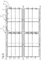
- FIG. 5 shows a top view of an embodiment of the screen system in which several screens are placed one after the other and next to each other.
- Each set of screen parts 8, 8' is attached to a torsion tube 6 respectively.
- Each torsion tube 6 is connected to a guide member 7 and can move translationally in relation to it.
- a number of screens are attached to a first movable pulling cable 9 and a second movable pulling cable 9'.
- Each of these cables is part of a number of cables, whereby the number of first pulling cables 9' and the several second pulling cables 9' as a whole can be moved to simultaneously change the effective surface area of each of the screens.
Landscapes
- Engineering & Computer Science (AREA)
- Structural Engineering (AREA)
- Life Sciences & Earth Sciences (AREA)
- Environmental Sciences (AREA)
- Architecture (AREA)
- Civil Engineering (AREA)
- Operating, Guiding And Securing Of Roll- Type Closing Members (AREA)
- Blinds (AREA)
Claims (13)
- Schirmsystem, geeignet zur Abschirmung von z.B. Licht und/oder Wärme, aufweisend:ein erstes bewegliches Zugseil (9);einen Schirm (8, 8'), der an einem ersten Ende mit einem ersten Befestigungspunkt (5) und an einem zweiten Ende mit dem ersten beweglichen Zugseil (9) verbunden ist;ein zweites bewegliches Zugseil (9'), wobei der erste Befestigungspunkt (5) mit dem zweiten beweglichen Zugseil verbunden ist; undeinen ersten und zweiten Motor (13, 13') zum Bewegen des ersten (9) bzw. zweiten beweglichen Zugseils (9');eine Steuereinheit (14), die den ersten und zweiten Motor (13, 13') steuert,dadurch gekennzeichnet, dassdie Steuereinheit (14) so ausgebildet ist, dass sie den ersten Motor und den zweiten Motor (13, 13') unabhängig voneinander steuert, und so konfiguriert ist, dass sie den ersten und den zweiten Motor (13, 13') so steuert, dass das Schirmsystem in zumindest zwei der folgenden drei Betriebsmodi arbeitet:translatorische Bewegung des Schirms (8, 8'), während eine effektive Länge des Schirms (8, 8') konstant bleibt;nicht-translatorische Bewegung des Schirms (8, 8'), während eine effektive Länge des Schirms (8, 8') variiert;translatorische Bewegung des Schirms (8, 8'), wobei eine effektive Länge des Schirms (8, 8') variiert;
- Schirmsystem nach Anspruch 1, wobei der Schirm einen ersten Schirmabschnitt (8) und einen zweiten Schirmabschnitt (8') umfasst, die beide mittels eines Torsionsrohrs (6) miteinander verbunden sind, wobei das Torsionsrohr (6) so ausgebildet ist, dass es rotiert, um den ersten und den zweiten Schirmabschnitt (8, 8') auf das Torsionsrohr (6) aufzurollen und straff zu halten.
- Schirmsystem nach Anspruch 2, wobei der erste Schirmabschnitt (8) und der zweite Schirmabschnitt (8') gleichzeitig und übereinander aufgerollt werden.
- Schirmsystem nach Anspruch 2 oder 3, ferner aufweisend eine Torsionsfeder, um die Drehbewegung des Torsionsrohrs (6) unter Federspannung zu setzen.
- Schirmsystem nach Anspruch 4, wobei ein erstes Ende der Torsionsfeder (10) mit dem Torsionsrohr verbunden ist und wobei ein zweites Ende der Torsionsfeder (10) mit einem drehfesten zweiten Befestigungspunkt verbunden ist.
- Schirmsystem nach Anspruch 5, wobei der drehfeste zweite Befestigungspunkt ein feststehendes Führungselement (11A) aufweist, zu dem oder in das sich das zweite Ende der Torsionsfeder (10) nur translatorisch bewegen kann.
- Schirmsystem nach einem der Ansprüche 2 bis 6, wobei der erste Schirmabschnitt (8) an einem ersten Ende mit dem ersten Befestigungspunkt (5) und an einem zweiten Ende mit dem Torsionsrohr (10) verbunden ist, und wobei der zweite Schirmabschnitt (8') an einem ersten Ende mit dem Torsionsrohr (6) und an einem zweiten Ende mit dem ersten beweglichen Zugseil (9) verbunden ist.
- Schirmsystem nach Anspruch 7, wobei der erste Schirmabschnitt (8) um das Torsionsrohr (6) über eine von dem ersten beweglichen Zugseil (9) abgewandten Seite des Torsionsrohrs (6) gewickelt ist, und wobei der zweite Schirmabschnitt (8') um das Torsionsrohr (6) über eine dem ersten beweglichen Zugseil (9) zugewandten Seite des Torsionsrohrs (6) gewickelt ist.
- Schirmsystem nach einem der Ansprüche 2 bis 8, wobei der erste und/oder der zweite Schirmabschnitt (8, 8') eine photovoltaische Zelle aufweist.
- Schirmsystem nach einem der Ansprüche 1 bis 9, wobei eine Mehrzahl an Schirmen, jeweils wie in den vorherigen Ansprüchen definiert, an einem ersten oder einem zweiten beweglichen Zugseil (9, 9') befestigt ist.
- Schirmsystem nach einem der Ansprüche 1 bis 10, wobei ein erstes und/oder ein zweites bewegliches Zugseil (9, 9') Teil einer Mehrzahl an Zugseilen ist.
- Schirmsystem nach einem der Ansprüche 1 bis 11, wobei ein erstes oder ein zweites bewegliches Zugseil (9, 9') mit einem ersten Ende an oder um eine erste rotierende Trommel und mit einem zweiten Ende an oder um eine zweite rotierende Trommel befestigt ist, und wobei die erste und/oder die zweite rotierende Trommel, welche von einem der ersten und zweiten Motoren (13, 13') in Bewegung gesetzt werden, synchron rotieren.
- Gebäude (19), wie z.B. ein Gewächshaus, aufweisend:eine oder mehrere lichtdurchlässige Öffnungen (16), wie z.B. Fenster;das Schirmsystem nach einem der Ansprüche 1 bis 12 zur Regelung der Lichtmenge, die durch die eine oder die mehreren lichtdurchlässigen Öffnungen in das Gebäude gelangt.
Applications Claiming Priority (1)
| Application Number | Priority Date | Filing Date | Title |
|---|---|---|---|
| NL2021263A NL2021263B1 (nl) | 2018-07-06 | 2018-07-06 | Doeksysteem en gebouw |
Publications (2)
| Publication Number | Publication Date |
|---|---|
| EP3594440A1 EP3594440A1 (de) | 2020-01-15 |
| EP3594440B1 true EP3594440B1 (de) | 2022-10-26 |
Family
ID=63405322
Family Applications (1)
| Application Number | Title | Priority Date | Filing Date |
|---|---|---|---|
| EP19185030.4A Active EP3594440B1 (de) | 2018-07-06 | 2019-07-08 | Schirmsystem und gebäude |
Country Status (2)
| Country | Link |
|---|---|
| EP (1) | EP3594440B1 (de) |
| NL (1) | NL2021263B1 (de) |
Family Cites Families (5)
| Publication number | Priority date | Publication date | Assignee | Title |
|---|---|---|---|---|
| DE3728913A1 (de) * | 1987-08-29 | 1987-12-17 | Werner Moshacke | Vorrichtung fuer langbahnige markisen mit schienenfuehrung |
| NL1005326C2 (nl) * | 1997-02-20 | 1998-08-24 | Patrick Franciscus Johannes Va | Afscherming en samenstel van een aantal van dergelijke afschermingen. |
| DE202006004615U1 (de) * | 2005-03-21 | 2006-06-14 | Vajsman, Peter | Sonnenschutzvorrichtung |
| WO2007083328A1 (en) * | 2006-01-17 | 2007-07-26 | Novi Stil Doo | Method for unwinding/ winding a laminar sheet and winding structure for covering areas suitable for implementing said method. |
| DE202007009563U1 (de) * | 2007-07-06 | 2007-11-08 | Stefanakis, Jannis, Dipl.-Ing. | Photovoltaikmarkise |
-
2018
- 2018-07-06 NL NL2021263A patent/NL2021263B1/nl not_active IP Right Cessation
-
2019
- 2019-07-08 EP EP19185030.4A patent/EP3594440B1/de active Active
Also Published As
| Publication number | Publication date |
|---|---|
| EP3594440A1 (de) | 2020-01-15 |
| NL2021263B1 (nl) | 2020-01-16 |
Similar Documents
| Publication | Publication Date | Title |
|---|---|---|
| US20230228094A1 (en) | Awning apparatus | |
| EP2021572B1 (de) | Gitteranordnung für eine fenster- oder türöffnung | |
| WO1998014672A1 (en) | Covering mechanism for a greenhouse | |
| JP5852957B2 (ja) | 壁の開口部または窓を覆うための巻取装置 | |
| US20250038701A1 (en) | A cable supported mobile solar panel array apparatus and method | |
| CN118017909A (zh) | 一种建筑屋顶光伏板支架装置 | |
| JP2012532260A5 (de) | ||
| EP3594440B1 (de) | Schirmsystem und gebäude | |
| KR101856851B1 (ko) | 접이식 대면적 차광 장치 | |
| KR102739265B1 (ko) | 차광장치 | |
| KR101133448B1 (ko) | 옥외형 차광장치 | |
| EP1334655B1 (de) | Aufwickeleinrichtung für eine Rollblende | |
| CN223626535U (zh) | 温室大棚棚间种植用遮阳装置 | |
| CN213639087U (zh) | 一种树木遮阳网装置 | |
| JP2017221119A (ja) | 農業用ハウス、農業用ハウスのカーテンシステム | |
| WO1992020893A1 (de) | Blendschutzvorrichtung für gebäude | |
| JP7690240B2 (ja) | ホルダ | |
| CN223219596U (zh) | 一种农业遮阳结构 | |
| KR101385092B1 (ko) | 온실용 커버 개폐장치 | |
| CN220897386U (zh) | 一种石斛种植用遮阳装置 | |
| US20250263976A1 (en) | Horizontal roll shade system with variable opacity | |
| EP1746216A2 (de) | Markise | |
| WO2024252388A1 (en) | A cable supported mobile solar panel array apparatus and method | |
| JP2013019145A (ja) | 電池式電動日除けネットスクリーン装置 | |
| CN119699083A (zh) | 观光温室大棚 |
Legal Events
| Date | Code | Title | Description |
|---|---|---|---|
| PUAI | Public reference made under article 153(3) epc to a published international application that has entered the european phase |
Free format text: ORIGINAL CODE: 0009012 |
|
| STAA | Information on the status of an ep patent application or granted ep patent |
Free format text: STATUS: THE APPLICATION HAS BEEN PUBLISHED |
|
| AK | Designated contracting states |
Kind code of ref document: A1 Designated state(s): AL AT BE BG CH CY CZ DE DK EE ES FI FR GB GR HR HU IE IS IT LI LT LU LV MC MK MT NL NO PL PT RO RS SE SI SK SM TR |
|
| AX | Request for extension of the european patent |
Extension state: BA ME |
|
| STAA | Information on the status of an ep patent application or granted ep patent |
Free format text: STATUS: REQUEST FOR EXAMINATION WAS MADE |
|
| 17P | Request for examination filed |
Effective date: 20200715 |
|
| RBV | Designated contracting states (corrected) |
Designated state(s): AL AT BE BG CH CY CZ DE DK EE ES FI FR GB GR HR HU IE IS IT LI LT LU LV MC MK MT NL NO PL PT RO RS SE SI SK SM TR |
|
| STAA | Information on the status of an ep patent application or granted ep patent |
Free format text: STATUS: EXAMINATION IS IN PROGRESS |
|
| 17Q | First examination report despatched |
Effective date: 20210408 |
|
| GRAP | Despatch of communication of intention to grant a patent |
Free format text: ORIGINAL CODE: EPIDOSNIGR1 |
|
| STAA | Information on the status of an ep patent application or granted ep patent |
Free format text: STATUS: GRANT OF PATENT IS INTENDED |
|
| INTG | Intention to grant announced |
Effective date: 20220610 |
|
| GRAS | Grant fee paid |
Free format text: ORIGINAL CODE: EPIDOSNIGR3 |
|
| GRAA | (expected) grant |
Free format text: ORIGINAL CODE: 0009210 |
|
| STAA | Information on the status of an ep patent application or granted ep patent |
Free format text: STATUS: THE PATENT HAS BEEN GRANTED |
|
| AK | Designated contracting states |
Kind code of ref document: B1 Designated state(s): AL AT BE BG CH CY CZ DE DK EE ES FI FR GB GR HR HU IE IS IT LI LT LU LV MC MK MT NL NO PL PT RO RS SE SI SK SM TR |
|
| REG | Reference to a national code |
Ref country code: GB Ref legal event code: FG4D |
|
| REG | Reference to a national code |
Ref country code: CH Ref legal event code: EP |
|
| REG | Reference to a national code |
Ref country code: AT Ref legal event code: REF Ref document number: 1527142 Country of ref document: AT Kind code of ref document: T Effective date: 20221115 |
|
| REG | Reference to a national code |
Ref country code: DE Ref legal event code: R096 Ref document number: 602019020988 Country of ref document: DE |
|
| REG | Reference to a national code |
Ref country code: IE Ref legal event code: FG4D |
|
| REG | Reference to a national code |
Ref country code: NL Ref legal event code: FP |
|
| REG | Reference to a national code |
Ref country code: LT Ref legal event code: MG9D |
|
| REG | Reference to a national code |
Ref country code: AT Ref legal event code: MK05 Ref document number: 1527142 Country of ref document: AT Kind code of ref document: T Effective date: 20221026 |
|
| PG25 | Lapsed in a contracting state [announced via postgrant information from national office to epo] |
Ref country code: SE Free format text: LAPSE BECAUSE OF FAILURE TO SUBMIT A TRANSLATION OF THE DESCRIPTION OR TO PAY THE FEE WITHIN THE PRESCRIBED TIME-LIMIT Effective date: 20221026 Ref country code: PT Free format text: LAPSE BECAUSE OF FAILURE TO SUBMIT A TRANSLATION OF THE DESCRIPTION OR TO PAY THE FEE WITHIN THE PRESCRIBED TIME-LIMIT Effective date: 20230227 Ref country code: NO Free format text: LAPSE BECAUSE OF FAILURE TO SUBMIT A TRANSLATION OF THE DESCRIPTION OR TO PAY THE FEE WITHIN THE PRESCRIBED TIME-LIMIT Effective date: 20230126 Ref country code: LT Free format text: LAPSE BECAUSE OF FAILURE TO SUBMIT A TRANSLATION OF THE DESCRIPTION OR TO PAY THE FEE WITHIN THE PRESCRIBED TIME-LIMIT Effective date: 20221026 Ref country code: FI Free format text: LAPSE BECAUSE OF FAILURE TO SUBMIT A TRANSLATION OF THE DESCRIPTION OR TO PAY THE FEE WITHIN THE PRESCRIBED TIME-LIMIT Effective date: 20221026 Ref country code: ES Free format text: LAPSE BECAUSE OF FAILURE TO SUBMIT A TRANSLATION OF THE DESCRIPTION OR TO PAY THE FEE WITHIN THE PRESCRIBED TIME-LIMIT Effective date: 20221026 Ref country code: AT Free format text: LAPSE BECAUSE OF FAILURE TO SUBMIT A TRANSLATION OF THE DESCRIPTION OR TO PAY THE FEE WITHIN THE PRESCRIBED TIME-LIMIT Effective date: 20221026 |
|
| PG25 | Lapsed in a contracting state [announced via postgrant information from national office to epo] |
Ref country code: RS Free format text: LAPSE BECAUSE OF FAILURE TO SUBMIT A TRANSLATION OF THE DESCRIPTION OR TO PAY THE FEE WITHIN THE PRESCRIBED TIME-LIMIT Effective date: 20221026 Ref country code: PL Free format text: LAPSE BECAUSE OF FAILURE TO SUBMIT A TRANSLATION OF THE DESCRIPTION OR TO PAY THE FEE WITHIN THE PRESCRIBED TIME-LIMIT Effective date: 20221026 Ref country code: LV Free format text: LAPSE BECAUSE OF FAILURE TO SUBMIT A TRANSLATION OF THE DESCRIPTION OR TO PAY THE FEE WITHIN THE PRESCRIBED TIME-LIMIT Effective date: 20221026 Ref country code: IS Free format text: LAPSE BECAUSE OF FAILURE TO SUBMIT A TRANSLATION OF THE DESCRIPTION OR TO PAY THE FEE WITHIN THE PRESCRIBED TIME-LIMIT Effective date: 20230226 Ref country code: HR Free format text: LAPSE BECAUSE OF FAILURE TO SUBMIT A TRANSLATION OF THE DESCRIPTION OR TO PAY THE FEE WITHIN THE PRESCRIBED TIME-LIMIT Effective date: 20221026 Ref country code: GR Free format text: LAPSE BECAUSE OF FAILURE TO SUBMIT A TRANSLATION OF THE DESCRIPTION OR TO PAY THE FEE WITHIN THE PRESCRIBED TIME-LIMIT Effective date: 20230127 |
|
| P01 | Opt-out of the competence of the unified patent court (upc) registered |
Effective date: 20230515 |
|
| REG | Reference to a national code |
Ref country code: DE Ref legal event code: R097 Ref document number: 602019020988 Country of ref document: DE |
|
| PG25 | Lapsed in a contracting state [announced via postgrant information from national office to epo] |
Ref country code: SM Free format text: LAPSE BECAUSE OF FAILURE TO SUBMIT A TRANSLATION OF THE DESCRIPTION OR TO PAY THE FEE WITHIN THE PRESCRIBED TIME-LIMIT Effective date: 20221026 Ref country code: RO Free format text: LAPSE BECAUSE OF FAILURE TO SUBMIT A TRANSLATION OF THE DESCRIPTION OR TO PAY THE FEE WITHIN THE PRESCRIBED TIME-LIMIT Effective date: 20221026 Ref country code: EE Free format text: LAPSE BECAUSE OF FAILURE TO SUBMIT A TRANSLATION OF THE DESCRIPTION OR TO PAY THE FEE WITHIN THE PRESCRIBED TIME-LIMIT Effective date: 20221026 Ref country code: DK Free format text: LAPSE BECAUSE OF FAILURE TO SUBMIT A TRANSLATION OF THE DESCRIPTION OR TO PAY THE FEE WITHIN THE PRESCRIBED TIME-LIMIT Effective date: 20221026 Ref country code: CZ Free format text: LAPSE BECAUSE OF FAILURE TO SUBMIT A TRANSLATION OF THE DESCRIPTION OR TO PAY THE FEE WITHIN THE PRESCRIBED TIME-LIMIT Effective date: 20221026 |
|
| PG25 | Lapsed in a contracting state [announced via postgrant information from national office to epo] |
Ref country code: SK Free format text: LAPSE BECAUSE OF FAILURE TO SUBMIT A TRANSLATION OF THE DESCRIPTION OR TO PAY THE FEE WITHIN THE PRESCRIBED TIME-LIMIT Effective date: 20221026 Ref country code: AL Free format text: LAPSE BECAUSE OF FAILURE TO SUBMIT A TRANSLATION OF THE DESCRIPTION OR TO PAY THE FEE WITHIN THE PRESCRIBED TIME-LIMIT Effective date: 20221026 |
|
| PLBE | No opposition filed within time limit |
Free format text: ORIGINAL CODE: 0009261 |
|
| STAA | Information on the status of an ep patent application or granted ep patent |
Free format text: STATUS: NO OPPOSITION FILED WITHIN TIME LIMIT |
|
| 26N | No opposition filed |
Effective date: 20230727 |
|
| PG25 | Lapsed in a contracting state [announced via postgrant information from national office to epo] |
Ref country code: SI Free format text: LAPSE BECAUSE OF FAILURE TO SUBMIT A TRANSLATION OF THE DESCRIPTION OR TO PAY THE FEE WITHIN THE PRESCRIBED TIME-LIMIT Effective date: 20221026 |
|
| PG25 | Lapsed in a contracting state [announced via postgrant information from national office to epo] |
Ref country code: MC Free format text: LAPSE BECAUSE OF FAILURE TO SUBMIT A TRANSLATION OF THE DESCRIPTION OR TO PAY THE FEE WITHIN THE PRESCRIBED TIME-LIMIT Effective date: 20221026 |
|
| PG25 | Lapsed in a contracting state [announced via postgrant information from national office to epo] |
Ref country code: MC Free format text: LAPSE BECAUSE OF FAILURE TO SUBMIT A TRANSLATION OF THE DESCRIPTION OR TO PAY THE FEE WITHIN THE PRESCRIBED TIME-LIMIT Effective date: 20221026 |
|
| REG | Reference to a national code |
Ref country code: CH Ref legal event code: PL |
|
| PG25 | Lapsed in a contracting state [announced via postgrant information from national office to epo] |
Ref country code: LU Free format text: LAPSE BECAUSE OF NON-PAYMENT OF DUE FEES Effective date: 20230708 |
|
| GBPC | Gb: european patent ceased through non-payment of renewal fee |
Effective date: 20230708 |
|
| PG25 | Lapsed in a contracting state [announced via postgrant information from national office to epo] |
Ref country code: LU Free format text: LAPSE BECAUSE OF NON-PAYMENT OF DUE FEES Effective date: 20230708 |
|
| REG | Reference to a national code |
Ref country code: IE Ref legal event code: MM4A |
|
| PG25 | Lapsed in a contracting state [announced via postgrant information from national office to epo] |
Ref country code: CH Free format text: LAPSE BECAUSE OF NON-PAYMENT OF DUE FEES Effective date: 20230731 Ref country code: GB Free format text: LAPSE BECAUSE OF NON-PAYMENT OF DUE FEES Effective date: 20230708 |
|
| PG25 | Lapsed in a contracting state [announced via postgrant information from national office to epo] |
Ref country code: IT Free format text: LAPSE BECAUSE OF FAILURE TO SUBMIT A TRANSLATION OF THE DESCRIPTION OR TO PAY THE FEE WITHIN THE PRESCRIBED TIME-LIMIT Effective date: 20221026 |
|
| PG25 | Lapsed in a contracting state [announced via postgrant information from national office to epo] |
Ref country code: IE Free format text: LAPSE BECAUSE OF NON-PAYMENT OF DUE FEES Effective date: 20230708 |
|
| PG25 | Lapsed in a contracting state [announced via postgrant information from national office to epo] |
Ref country code: IE Free format text: LAPSE BECAUSE OF NON-PAYMENT OF DUE FEES Effective date: 20230708 |
|
| PG25 | Lapsed in a contracting state [announced via postgrant information from national office to epo] |
Ref country code: BG Free format text: LAPSE BECAUSE OF FAILURE TO SUBMIT A TRANSLATION OF THE DESCRIPTION OR TO PAY THE FEE WITHIN THE PRESCRIBED TIME-LIMIT Effective date: 20221026 |
|
| PG25 | Lapsed in a contracting state [announced via postgrant information from national office to epo] |
Ref country code: BG Free format text: LAPSE BECAUSE OF FAILURE TO SUBMIT A TRANSLATION OF THE DESCRIPTION OR TO PAY THE FEE WITHIN THE PRESCRIBED TIME-LIMIT Effective date: 20221026 |
|
| PG25 | Lapsed in a contracting state [announced via postgrant information from national office to epo] |
Ref country code: CY Free format text: LAPSE BECAUSE OF FAILURE TO SUBMIT A TRANSLATION OF THE DESCRIPTION OR TO PAY THE FEE WITHIN THE PRESCRIBED TIME-LIMIT; INVALID AB INITIO Effective date: 20190708 |
|
| PG25 | Lapsed in a contracting state [announced via postgrant information from national office to epo] |
Ref country code: HU Free format text: LAPSE BECAUSE OF FAILURE TO SUBMIT A TRANSLATION OF THE DESCRIPTION OR TO PAY THE FEE WITHIN THE PRESCRIBED TIME-LIMIT; INVALID AB INITIO Effective date: 20190708 |
|
| PGFP | Annual fee paid to national office [announced via postgrant information from national office to epo] |
Ref country code: NL Payment date: 20250726 Year of fee payment: 7 |
|
| PGFP | Annual fee paid to national office [announced via postgrant information from national office to epo] |
Ref country code: DE Payment date: 20250729 Year of fee payment: 7 |
|
| PGFP | Annual fee paid to national office [announced via postgrant information from national office to epo] |
Ref country code: BE Payment date: 20250728 Year of fee payment: 7 |
|
| PGFP | Annual fee paid to national office [announced via postgrant information from national office to epo] |
Ref country code: FR Payment date: 20250725 Year of fee payment: 7 |
|
| PG25 | Lapsed in a contracting state [announced via postgrant information from national office to epo] |
Ref country code: TR Free format text: LAPSE BECAUSE OF FAILURE TO SUBMIT A TRANSLATION OF THE DESCRIPTION OR TO PAY THE FEE WITHIN THE PRESCRIBED TIME-LIMIT Effective date: 20221026 |