EP3594440B1 - Screen system and building - Google Patents
Screen system and building Download PDFInfo
- Publication number
- EP3594440B1 EP3594440B1 EP19185030.4A EP19185030A EP3594440B1 EP 3594440 B1 EP3594440 B1 EP 3594440B1 EP 19185030 A EP19185030 A EP 19185030A EP 3594440 B1 EP3594440 B1 EP 3594440B1
- Authority
- EP
- European Patent Office
- Prior art keywords
- screen
- pulling cable
- torsion tube
- screen system
- movable pulling
- Prior art date
- Legal status (The legal status is an assumption and is not a legal conclusion. Google has not performed a legal analysis and makes no representation as to the accuracy of the status listed.)
- Active
Links
- 230000033001 locomotion Effects 0.000 claims description 23
- 238000009434 installation Methods 0.000 description 7
- 238000004804 winding Methods 0.000 description 7
- 238000003898 horticulture Methods 0.000 description 5
- 238000013461 design Methods 0.000 description 4
- 230000009347 mechanical transmission Effects 0.000 description 4
- 239000004744 fabric Substances 0.000 description 3
- 238000000034 method Methods 0.000 description 3
- 230000001960 triggered effect Effects 0.000 description 3
- 230000003247 decreasing effect Effects 0.000 description 2
- 238000006073 displacement reaction Methods 0.000 description 2
- 230000000694 effects Effects 0.000 description 2
- 238000005516 engineering process Methods 0.000 description 2
- 238000005096 rolling process Methods 0.000 description 2
- 238000007664 blowing Methods 0.000 description 1
- 230000007423 decrease Effects 0.000 description 1
- 238000011161 development Methods 0.000 description 1
- 230000005611 electricity Effects 0.000 description 1
- 238000012423 maintenance Methods 0.000 description 1
- 239000000463 material Substances 0.000 description 1
- 238000012986 modification Methods 0.000 description 1
- 230000004048 modification Effects 0.000 description 1
- 238000009343 monoculture Methods 0.000 description 1
- 230000000737 periodic effect Effects 0.000 description 1
- 238000011084 recovery Methods 0.000 description 1
- 238000000926 separation method Methods 0.000 description 1
- 238000012546 transfer Methods 0.000 description 1
Images


Classifications
-
- E—FIXED CONSTRUCTIONS
- E06—DOORS, WINDOWS, SHUTTERS, OR ROLLER BLINDS IN GENERAL; LADDERS
- E06B—FIXED OR MOVABLE CLOSURES FOR OPENINGS IN BUILDINGS, VEHICLES, FENCES OR LIKE ENCLOSURES IN GENERAL, e.g. DOORS, WINDOWS, BLINDS, GATES
- E06B9/00—Screening or protective devices for wall or similar openings, with or without operating or securing mechanisms; Closures of similar construction
- E06B9/24—Screens or other constructions affording protection against light, especially against sunshine; Similar screens for privacy or appearance; Slat blinds
- E06B9/40—Roller blinds
-
- A—HUMAN NECESSITIES
- A01—AGRICULTURE; FORESTRY; ANIMAL HUSBANDRY; HUNTING; TRAPPING; FISHING
- A01G—HORTICULTURE; CULTIVATION OF VEGETABLES, FLOWERS, RICE, FRUIT, VINES, HOPS OR SEAWEED; FORESTRY; WATERING
- A01G9/00—Cultivation in receptacles, forcing-frames or greenhouses; Edging for beds, lawn or the like
- A01G9/22—Shades or blinds for greenhouses, or the like
- A01G9/227—Shades or blinds for greenhouses, or the like rolled up during non-use
-
- E—FIXED CONSTRUCTIONS
- E06—DOORS, WINDOWS, SHUTTERS, OR ROLLER BLINDS IN GENERAL; LADDERS
- E06B—FIXED OR MOVABLE CLOSURES FOR OPENINGS IN BUILDINGS, VEHICLES, FENCES OR LIKE ENCLOSURES IN GENERAL, e.g. DOORS, WINDOWS, BLINDS, GATES
- E06B9/00—Screening or protective devices for wall or similar openings, with or without operating or securing mechanisms; Closures of similar construction
- E06B9/24—Screens or other constructions affording protection against light, especially against sunshine; Similar screens for privacy or appearance; Slat blinds
- E06B2009/2423—Combinations of at least two screens
- E06B2009/2447—Parallel screens
- E06B2009/2458—Parallel screens moving simultaneously
-
- E—FIXED CONSTRUCTIONS
- E06—DOORS, WINDOWS, SHUTTERS, OR ROLLER BLINDS IN GENERAL; LADDERS
- E06B—FIXED OR MOVABLE CLOSURES FOR OPENINGS IN BUILDINGS, VEHICLES, FENCES OR LIKE ENCLOSURES IN GENERAL, e.g. DOORS, WINDOWS, BLINDS, GATES
- E06B9/00—Screening or protective devices for wall or similar openings, with or without operating or securing mechanisms; Closures of similar construction
- E06B9/24—Screens or other constructions affording protection against light, especially against sunshine; Similar screens for privacy or appearance; Slat blinds
- E06B9/40—Roller blinds
- E06B2009/405—Two rollers
-
- Y—GENERAL TAGGING OF NEW TECHNOLOGICAL DEVELOPMENTS; GENERAL TAGGING OF CROSS-SECTIONAL TECHNOLOGIES SPANNING OVER SEVERAL SECTIONS OF THE IPC; TECHNICAL SUBJECTS COVERED BY FORMER USPC CROSS-REFERENCE ART COLLECTIONS [XRACs] AND DIGESTS
- Y02—TECHNOLOGIES OR APPLICATIONS FOR MITIGATION OR ADAPTATION AGAINST CLIMATE CHANGE
- Y02A—TECHNOLOGIES FOR ADAPTATION TO CLIMATE CHANGE
- Y02A40/00—Adaptation technologies in agriculture, forestry, livestock or agroalimentary production
- Y02A40/10—Adaptation technologies in agriculture, forestry, livestock or agroalimentary production in agriculture
- Y02A40/25—Greenhouse technology, e.g. cooling systems therefor
Description
- The present invention relates to a screen system. Furthermore, the invention relates to a building provided with such a screen system. The screen system is suitable for shielding, for example, light and/or heat. More specifically, the invention relates to a screen system intended for greenhouse horticulture. The invention also pertains to a building used for greenhouse horticulture, as well as a greenhouse in which the screen system is installed.
- In greenhouse horticulture, attention is paid to providing the ideal growth environment for, for example, a monoculture of plants. Offering the right amount of heat and light to all individual plants is an important part of this. This right amount of heat is characterized not only by the desired amount of heat, but also by offering it as evenly as possible so that all individual plants undergo a similar development.
- In view of the increasing number of working environments in greenhouse horticulture, such as greenhouses, the efficiency and sustainability of a screen system is becoming increasingly important for growers and investors.
- Known in the art is the screen system disclosed in
EP 0 860 578 A1 , comprising a number of tension rollers, each having its free ends movably bearing-mounted in two lateral guides and each being rotatable around the longitudinal center line of the relevant tension roller. Each tension roller comprises a tension spring, and the tension rollers are interconnected by screen cloth parts. The tension springs in the tension rollers are biased such that the screen tends to assume a rolled-in condition and is extendible against the bias of the tension springs. - Known in the art is the device disclosed in
DE 3728913 A1 , which is for a broad web awning, in which the awning cloth is divided up into part-webs and in each case two part-webs or part-web portions are assigned to a particular cloth roller, which for their part are capable of travelling in longitudinal rails. - Known in the art is a slat, folding window blind, or extendable awning disclosed in
DE 20 2007 009563 U1 , which fulfills a shading function of 100% and can produce at the same time electricity or heat for a building. - Known in the art is the sunshade assembly disclosed in
DE 20 2006 004615 U1 - Known in the art are the winding method and structure disclosed in
WO 2007/083328 . The document discloses a method for unwinding/winding a laminar sheet arranged so as to cover an area and forming part of a winding structure, which comprises a supporting structure associated with the area and including a cylinder for supporting said laminar sheet that identifies a first longitudinal axis of rotation, drive means for rotating the cylinder around the first longitudinal axis and elastic means cooperating mechanically with the drive means during the unwinding/winding of the laminar sheet. The unwinding of the laminar sheet from the cylinder is due to the effect of the rotation of the cylinder induced by the drive means, while the winding of the laminar sheet onto the cylinder is due to the effect of the recovery of the mechanical energy stored by the elastic means during the unwinding of the laminar sheet. - Further types of screen systems that are known from the most recent technology include a variety of screens characterized by the properties that contribute to the aforementioned goal, namely the percentage of heat they allow to pass through and the amount of heat they shield. The screen systems also include a variety of cables that are used to move the screens and/or keep them in place.
-
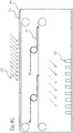
Figure 1 shows an installation based on the most recent technology. The system consists of ascreen 1 attached on one side to astationary point 5, for example a beam or lattice or other kind of stationary part of a building, and on the other side to ascreen 2.Carrier 2 can be moved vis-à-vis astationary support cable 3, on which screen 1 rests. The surface ofscreen 1 can be adjusted by setting in motion apulling cable 4, which runs undersupport cable 3, and which is attached tocarrier 2. For this purpose, the familiar system includes a motor for movingpulling cable 4 and a control unit for controlling the motor for the complete unfolding or complete retraction ofscreen 1. - When adjusting
screen 1, it is pulled bycarrier 2 oversupport cable 3 to a desired location. To prevent wear ofscreen 1 due to the friction betweensupport cable 3 andscreen 1, the material type ofsupport cable 3 is carefully selected. These properties are incompatible with the properties for pullingcable 4, which are aimed in particular at being able to transfer tensile forces. - Despite the separate use of
support cables 3 and pullingcables 4, usually 1 pulling cable per 5 support cables, there is still relatively a lot of wear and tear on the aforementioned screen system. A further disadvantage of the common screen system is that the use of a separate cable for each required function (drive and support) means that two different cable networks have to be stretched over the entire length of the building. This results in a complex, maintenance-sensitive and costly installation. - One of the aims of the present invention is to provide a screen system in which the above-mentioned disadvantages do not or hardly occur.
- This objective is achieved by means of the screen system as defined in accompanying
claim 1, wherein it comprises a control unit equipped to control the first motor and the second motor independently of each other, and configured to control the first and second motors such that the screen system is operational in at least two of the following three operating modes: an effective length of the screen remains constant, whereas the screen moves translationally, the effective length of the screen varies, whereas the screen does not move translationally, or the effective length of the screen varies, and the screen moves translationally. In this way, the light can be shielded more evenly and as required. Because the position of the sun changes during the day, a moving screen can be used to compensate for this change. However, if the light distribution is homogenous, it is still possible to control the effective screen over time by moving the screen, which has been at least partially opened. - The screen may comprise a first screen part and a second screen part connected to each other by means of a torsion tube, wherein the torsion tube is configured to rotate so as to roll the first and second screen parts onto the torsion tube and to keep it taut.
- With the common screen system, there is relatively lots of friction between the stationary support cable and the sometimes-moving screen. By replacing the usual screen by two screen parts which are connected by a torsion tube, a screen system is realized in which the screen parts are tightly stretched. This reduces the mutual movement between the screen and the cable on which it rests. This allows for omitting the support cable and lets the screen rest directly on the pulling cable while the risk of screen damage remains limited.
- In the screen system according to the invention, the first screen part and the second screen part can be rolled up simultaneously and on top of each other. This makes it possible that, despite the separation of the screen, a single roll-up location and roll-up movement are sufficient to roll up the screen. In order to make this possible, the screen system can include a torsion spring for placing the rotating movement of the torsion tube under spring tension. When using a torsion spring, the torsion tube does not require an electrical connection as would be necessary if an internal motor were used.
- A first end of the torsion spring can be connected to the torsion tube and a second end of the torsion spring can be connected to a rotation-fixed second attachment point. This attachment as well as the orientation of the torsion spring determines the direction of rotation in which the torsion tube will rotate.
- In a preferred embodiment, the rotation-fixed second attachment point includes a fixed guide member in relation to which or into which the second end of the torsion spring can only move translationally. This movement of the torsion tube allows the torsion tube to move with the enlargement and/or reduction of the effective surface area of the screen.
- In an embodiment, the first screen part is connected at a first end thereof to the first attachment point and is connected at a second end thereof to the torsion tube. The second screen part is connected at a first end to the torsion tube and at a second end to a first movable pulling cable. Preferably, the first screen part is wrapped around the torsion tube at a side of the torsion tube facing away from the first movable pulling cable and the second screen part is wrapped around the torsion tube at a side of the torsion tube facing towards the first movable pulling cable. In this way, the first screen part is held above the pulling cable moving underneath the screen part. The second screen part can be directly supported by the pulling cable that moves with this screen part. Because the second screen part does not move much, if at all, compared to the first movable pulling cable, there is little or no wear as a result of friction.
- The first movable pulling cable can be set in motion by the first motor that is controlled by the control unit. With this first motor and control unit, the effective surface area of the screen can be increased or decreased with the result that the plants in the greenhouse can be shielded as needed.
- The screen system also includes a second movable pulling cable, with the first attachment point connected to the second movable pulling cable. The function of this second pulling cable is that the first attachment point can be set in motion. A second motor is used to set in motion the second movable pulling cable and thus the first attachment point, which is also controlled by the control unit. A further function of the second movable pulling cable is to prevent the screen parts from blowing upwards as a result of air flow, such as, the wind when the greenhouse is partially open.
- In the aforementioned common system, the screen is attached on one side to a stationary point. This means that in the immediate vicinity of this point there is always a shadow on the plants at the same spot. This makes it difficult to distribute the light evenly across the plants. The screen system of the present invention makes it possible to move the screen so that the position of the screen can be adjusted during the day or other time interval in such a way that each plant has experienced a mainly equal time-average exposure. An alternative aspect made possible by this improved mobility is that a screen system equipped with a screen with a characteristic heat reduction, for example 60%, can be configured according to an effective surface area and a periodic displacement, so that the screen can function as a screen with a lower heat reduction, for example between 0 and 60%.
- A variety of screens, each as defined above, can be attached to a first or a second movable pulling cable. This allows for a system in which several screens or screen parts are moved by means of a single pulling cable.
- The first and/or second movable pulling cable may be part of a host of first and/or second pulling cables, respectively, which are arranged in parallel. A screen part may be connected to one or more first and/or second moving pulling cables. In addition, several screen parts can be placed next to each other. In a preferred embodiment, several screens are placed one after the other and next to each other, which are operated by the host of first and/or second pulling cables.
- In the screen systems described above, the first or second movable pulling cable may be attached to or around a first movable coil by a first end and attached to or around a second movable coil by a second end. In this case, the first and/or second movable coil, triggered by one or the first or second motor, can run synchronously. A single motor can be used, which rotates the first and second movable coils synchronously by means of a mechanical transmission. It is also possible to use a separate motor for each movable coil. Here, too, the coils rotate synchronously.
- The first and/or second screen part may include a photovoltaic cell, with which solar energy can be generated.
- The screen system is especially designed to be used in a building, such as a greenhouse, wherein it can be used in the immediate vicinity of one or more light-permeable openings, such as windows, to control the amount of light entering the building through one or more light-permeable openings.
- In the following section, the invention is further discussed on the basis of the attached figures in which:
-
Figure 1 shows a common screen system; -
Figure 2A shows a side view of an embodiment, wherein the first attachment point is fixed to a stationary point; -
Figure 2B shows a side view of an embodiment, wherein the first attachment point is attached to a second movable pulling cable; -
Figure 2C shows a side view of an embodiment in which a number of screens are attached to a first and second moving pulling cable; -
Figure 3A shows a perspective view of a first and second screen part interconnected by a torsion tube andfigure 3B shows a detailed view of the torsion tube; -
Figure 4A shows a schematic side view of a further embodiment of the screen system in which a first and second movable pulling cable are looped around a first or second movable coil; -
Figure 4B shows a diagrammatic side view of a further embodiment of the screen system in which a first or second movable pulling cable are looped around a first and a second movable coil; -
Figure 4C shows an embodiment, wherein the screen system is placed in a user environment for greenhouse horticulture; -
Figure 5 shows a top view of an embodiment in which several screens and several first and second movable pulling cables are arranged. -
Figure 2A shows, for example, a side view of an embodiment of a screen system according to the invention. Here, afirst screen part 8 is attached with one end to a stationaryfirst attachment point 5 and with a second end to atorsion tube 6. In addition, a second screen part 8' with a first end is attached to thetorsion tube 6 and a second end is attached to a first movable pullingcable 9. It also shows aguide member 7 along whichtorsion tube 6 can move translationally. - The stationary first attachment point may be a lattice or beam, or any other stationary part of a building in which the screen system is installed.
- In
figure 2A a first movable pullingcable 9 can be moved in the horizontal direction. By moving the first movable pullingcable 9 to the right, the effective surface area of thescreen 8, 8' is increased, which rotatestorsion tube 6 counter clockwise and half of the distance covered by the first movable pullingcable 9 moves along theguide member 7. Rotating the first movable pullingcable 9 to the left, assuming that this movement does not attempt to movetorsion tube 6 to the left beyond thefirst attachment point 5, results in a reduction of the effective surface area of the screen, with thetorsion tube 6 rotating clockwise. Thefirst screen part 8 and a second screen part 8' will become equally longer or shorter. - It should be noted that, in practice,
torsion tube 6 is mainly supported by first pullingcables 9. However, becausetorsion tube 6 rolls up or down and because this movement corresponds to the movement of the first pullingcables 9, the risk of wear of the screen parts is small to negligible. - As a result of
torsion tube 6,screen parts 8, 8' are kept taut. In particular, thefirst screen part 8 is kept at a distance from the first pullingcable 9 and little to no friction will occur between these parts. - Another consequence of
torsion tube 6 is that this second screen part 8' also keeps it taut. However, this screen part can be laid with the first movable pullingcable 9. Because this screen part moves along with the pulling cable, there is little or no mutual movement. - It follows from the division of the screen that at a given displacement of the first movable pulling cable,
torsion tube 6 moves in the same direction and moves half of the distance along guide member. It should be noted that the torsion tube is configured to roll upscreen parts 8, 8' by pre-tension. - Although
first attachment point 5 is attached to a surface in this design, other surfaces are possible asfirst attachment point 5, such as an angle or a cylinder. -
Figure 2B shows a similar side view as infigure 2A . However, infigure 2B , thefirst attachment point 5 is connected to a second movable pulling cable 9' which can also be moved in the horizontal direction. - Moving first movable pulling
cable 9 and second movable pullingcable 9 "to the right or left simultaneously results inscreen parts torsion tube 6 moves equally alongguide member 7 to the right or left. The simultaneous movement to the left or to the right of the second pulling cable 9' as well as the movement to the opposite direction of the first pullingcable 9 has the result that the effective length of the screen formed by screen parts increases or decreases by 8,8'. In this case,torsion tube 6 does not move. -
Figure 2C shows a side view similar tofigures 2A and 2B . However, infigure 2C a number of screens are attached to a first pullingcable 9 and to a second pulling cable 9'. The movement of screen parts 8.8', or the enlargement and/or reduction of the effective surface area of the screen formed by these screen parts, is identical for the number of screen parts when they are attached to one and the same first movable pullingcable 9 and/or second movable pulling cable 9'. -
Figure 3A shows a perspective view ofscreen parts 8, 8' andtorsion tube 6.Figure 3B shows a view oftorsion tube 6.Torsion tube 6 visibly contains anouter tube 12 and atorsion spring 10. An end 10' oftorsion spring 10 is connected toouter tube 12 and another end to aguide member element 11A. A similarguide member element 11B is connected to theguide member element 11A by means of anarm 11C. Theguide member elements guide member 7.Guide member 7 can be equipped with a slot or groove into which guidemember elements - Due to
torsion spring 11, the rotational movement of theouter tube 12 is under spring tension compared to theguide member 7. Becauseguide member element 11A cannot rotate sinceguide member element 11B is held byarm 11C inguide member 7,torsion tube 6 tends to roll upscreen parts 8, 8'. However, this is prevented by first and/or second pullingcable 9, 9' and/or by firststationary attachment point 5 if present. - The demonstrated embodiment does not restrict the possibility of producing a torsion tube with a non-cylindrical shape.
-
Figure 3B also shows atorsion spring 10 on one side oftorsion tube 6. However, due to a symmetrical load, it is preferable to attach a torsion spring on the other side oftorsion tube 6 as well. -
Figure 4A shows a schematic side view of a design of the screen system according to the invention. The first movable pullingcable 9 and the second movable pullingcable 9's are guided around a couple ofcoils 15 each. At least one of thecoils 15 is generated by amotor 13, whereinmotors 13 are controlled, each independently, bycontrol unit 14. - In a possible embodiment, a first
movable coil 15, coupled with the first movable pulling cable, generated by afirst motor 13, a secondmovable coil 16, coupled with the second movable pulling cable, generated by asecond motor 13, and the first and second movable coils are placed 15 crosswise from each other. -
Figure 4B shows a diagrammatic side view of a different type of screen system according to the invention. Here, first movable pullingcable 9 and second movable pulling cable 9 'are each attached to a pair ofcoils 15. At least one ofcoils 15 is generated by amotor 13, withmotors 13 being generated, each independently, bycontrol unit 14. In contrast tofigure 4A , it is necessary to generate each of themovable coils 15 in order to allow movement in both directions. For this purpose, motors can be linked to each of themovable coils 15 by means of an unseen mechanical transmission. Each of themovable coils 15 can also be equipped with amotor 13. In these embodiment, unlikefigure 4A , pullingcables 9, 9' are winded inverted coils 15. Themotors 13 are then each independently controlled bycontrol unit 14. - For both embodiments, the pairs move synchronously in order to prevent the tension in the 9, 9' pulling cables from decreasing. In addition, for both embodiments, the separate control of the motors for the first 9' pulling cable and the second 9' pulling cable also means that the screen is enlarged, reduced or moved.
-
Figure 4B shows a similar side view asFig. 4A wherein a firstmovable coil 15 and a second movable coil are triggered by a first and a second motor system 13' which are controlled by acontrol unit 14. - This preferred embodiment has the strong advantage that only the first movable pulling cable has to be kept in tension in one direction only. The first and/or a second pulling cable is wound at one end on a
movable coil 15. The first and/or the second movable pulling cable is wound at another end on another movable coil. A pulling cable is triggered by a motor system 13'. Amovable coil 15 is directly controlled by a first motor as part of the motor system 13' wherein another movable coil may be set in motion by a second motor as part of the motor system 13' or may be set in motion indirectly by mechanical transmission of the first motor as part of the motor system 13'. Another movable coil may be set in motion by a second motor as part of the motor system 13' or may be set in motion indirectly by mechanical transmission of the first motor as part of the motor system 13'. - The
control unit 14, capable of controlling a first and second motor system on an individual basis, is capable of turning the screen to the right by moving themovable coils 15 in the opposite direction and releasing other movable coils. It is also able to move the screen to the left by moving the other movable coils in opposite directions and allowing themovable coils 15 to rotate freely. - An embodiment can be provided in which a torsion tube has a length of up to two hundred meters and includes forty tube elements, which have a diameter of sixty millimeters and a length of approximately five meters. The first and second screen parts have an effective length of two and a half meters and are attached every fifty centimeters to a first and possibly second pulling cable. In this case, the structure is hung in a subspace of a greenhouse which is called a section. A greenhouse, for example, can consist of fifteen sections and therefore assumes a width of seventy-five meters.
- If this embodiment is equipped with the installation shown in
Figure 4A , the first and second movable pulling cables shall each have a length of at least 150 meters. A total of at least one hundred and twenty kilometers of pulling cable shall therefore be installed over the entire greenhouse. - If this type of design is equipped with the installation shown in
Figure 4B , the first and second movable pulling cables will each have a length of at least seventy-five meters. For this reason, a total of at least sixty kilometers of pulling cable will be installed over the entire greenhouse. -
Figure 4C shows a schematic side view in which the screen system is placed in abuilding 19 that contains light-permeable openings 16 such as windows, in which the screen system shields light 17 from the objects to be screened off 18, for example plants. - The screen system changes the permeation of light 17 by enlarging, reducing or moving the effective surface area of the screen formed by
screen parts 8, 8'. The screen system distributes the minimal shadow present proportionally overobjects 18 to be screened off by moving the screen in the manner described above. - If
screen parts 8, 8' have a certain degree of light permeation, such as 50%, thesescreen parts 8, 8' can be used to achieve a time average light intensity between 50 and 100% of the maximum available light intensity for essentially anyobject 18 that is screened. An average of 50% is achieved by fully rolling out the screen, while an average of 100% is achieved by fully rolling up the screen. For the sake of simplicity, the protection of a fully rolled up screen has not been taken into account in this calculation. - However, if
screen parts 8, 8' have a light permeation degree of 0%, thesescreen parts 8, 8' can be used to achieve a time-average and spatially uniform luminous intensity between 0 and 100%. - Because of the fact that these screens are exposed to sunlight, an embodiment option is provided in which the first and second parts of the screen contain a photovoltaic cell. Current photovoltaic cells are known to be relatively rigid and vulnerable. A screen part of an installation, as is known in the technique, is wrinkled with sharp angles and unpredictable shapes. These properties are not necessarily compatible with known installations.
- The installation according to this document will keep the first and second screen parts taut, so that they are flat when rolled out. Also, the first and second screen parts are rolled up around a torsion coil so that they do not assume sharp or unexpected angles. This creates an environment in which it is possible to mount flexible photovoltaic cells.
-
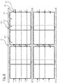
Figure 5 shows a top view of an embodiment of the screen system in which several screens are placed one after the other and next to each other. Each set ofscreen parts 8, 8' is attached to atorsion tube 6 respectively. Eachtorsion tube 6 is connected to aguide member 7 and can move translationally in relation to it. A number of screens are attached to a first movable pullingcable 9 and a second movable pulling cable 9'. Each of these cables is part of a number of cables, whereby the number of first pulling cables 9' and the several second pulling cables 9' as a whole can be moved to simultaneously change the effective surface area of each of the screens. - It should be clear to the professional that the present invention is not limited to the designs shown here, but that various modifications are possible without deviating from the scope of protection which is defined by the attached claims.
Claims (13)
- Screen system suitable for shielding, for example, light and/or heat, comprising:a first movable pulling cable (9);a screen (8, 8') connected at a first end to a first attachment point (5) and at a second end to the first movable pulling cable (9);a second movable pulling cable (9'), wherein the first attachment point (5) is connected to the second movable pulling cable; anda first and second motor (13, 13') for moving the first (9) and second movable pulling cable (9'), respectively;a control unit (14) controlling the first and second motors (13, 13');characterized in that saidcontrol unit (14) is equipped to control the first motor and the second motor (13, 13') independently of each other, and is configured to control the first and second motors (13, 13') such that the screen system is operational in at least two of the following three operating modes:an effective length of the screen (8, 8') remains constant, whereas the screen (8, 8') moves translationally;the effective length of the screen (8, 8') varies, whereas the screen (8, 8') does not move translationally;the effective length of the screen (8, 8') varies, and the screen (8, 8') moves translationally.
- Screen system according to claim 1, wherein the screen comprises a first screen part (8) and a second screen part (8') which are interconnected by means of a torsion tube (6), wherein the torsion tube (6) is configured to rotate so as to roll the first and second screen parts (8, 8') onto the torsion tube (6) and to keep it taut.
- Screen system according to claim 2, wherein the first screen part (8) and the second screen part (8') are rolled up simultaneously and one over the other.
- Screen system according to claim 2 or 3, further comprising a torsion spring for placing the rotating movement of the torsion tube (6) under spring tension.
- Screen system according to claim 4, wherein a first end of the torsion spring (10) is connected to the torsion tube and wherein a second end of the torsion spring (10) is connected to a rotation-fixed second attachment point.
- Screen system according to claim 5, wherein the rotation-fixed second attachment point includes a fixed guide member (11A) in relation to which or into which the second end of the torsion spring (10) can only move translationally.
- Screen system according to any one of claims 2-6, wherein the first screen part (8) is connected at a first end to the first attachment point (5) and at a second end to the torsion tube (10) and wherein the second screen part (8') is connected at a first end to the torsion tube (6) and at a second end to the first movable pulling cable (9).
- Screen system according to claim 7, wherein the first screen part (8) is wrapped around the torsion tube (6) at a side of the torsion tube (6) facing away from the first movable pulling cable (9) and wherein the second screen part (8') is wrapped around the torsion tube (6) at a side of the torsion tube (6) facing towards the first movable pulling cable (9).
- Screen system according to any one of claims 2-8, wherein the first and/or the second screen part (8, 8') includes a photovoltaic cell.
- Screen system according to one of the claims 1-9, wherein a plurality of screens, each as defined in the preceding claims, is attached to a first or a second movable pulling cable (9, 9').
- Screen system according to one of the claims 1-10, wherein a first and/or a second movable pulling cable (9, 9') is part of a plurality of pulling cables.
- Screen system according to any of the claims 1-11, wherein a first or a second movable pulling cable (9, 9') is attached with a first end thereof to or around a rotating reel and with a second end thereof to or around a second rotating reel and wherein the first and/or the second rotating reel, set in motion by one of the first and second motors (13, 13'), rotate synchronously.
- Building (19), such as a greenhouse, comprising:one or more light-permeable openings (16), such as windows;the screen system according to any one of claims 1-12 for controlling a quantity of light that passes through the one or more light-permeable openings in the building.
Applications Claiming Priority (1)
| Application Number | Priority Date | Filing Date | Title |
|---|---|---|---|
| NL2021263A NL2021263B1 (en) | 2018-07-06 | 2018-07-06 | CLOTHING SYSTEM AND BUILDING |
Publications (2)
| Publication Number | Publication Date |
|---|---|
| EP3594440A1 EP3594440A1 (en) | 2020-01-15 |
| EP3594440B1 true EP3594440B1 (en) | 2022-10-26 |
Family
ID=63405322
Family Applications (1)
| Application Number | Title | Priority Date | Filing Date |
|---|---|---|---|
| EP19185030.4A Active EP3594440B1 (en) | 2018-07-06 | 2019-07-08 | Screen system and building |
Country Status (2)
| Country | Link |
|---|---|
| EP (1) | EP3594440B1 (en) |
| NL (1) | NL2021263B1 (en) |
Family Cites Families (5)
| Publication number | Priority date | Publication date | Assignee | Title |
|---|---|---|---|---|
| DE3728913A1 (en) * | 1987-08-29 | 1987-12-17 | Werner Moshacke | DEVICE FOR LONG-TERM AWNINGS WITH RAIL GUIDE |
| NL1005326C2 (en) * | 1997-02-20 | 1998-08-24 | Patrick Franciscus Johannes Va | Shielding and assembly of a number of such shields. |
| DE202006004615U1 (en) * | 2005-03-21 | 2006-06-14 | Vajsman, Peter | Sunshade, with canopies on a winding shaft, has three vertical support rods on the ground and a controlled motor to drive the winding shaft |
| US20090301534A1 (en) * | 2006-01-17 | 2009-12-10 | Andrea Bettega | Method For The Unwinding/Winding a Laminar Sheet and Winding Structure For Covering Areas Suitable For Implementing Said Method |
| DE202007009563U1 (en) * | 2007-07-06 | 2007-11-08 | Stefanakis, Jannis, Dipl.-Ing. | photovoltaic awning |
-
2018
- 2018-07-06 NL NL2021263A patent/NL2021263B1/en active
-
2019
- 2019-07-08 EP EP19185030.4A patent/EP3594440B1/en active Active
Also Published As
| Publication number | Publication date |
|---|---|
| NL2021263B1 (en) | 2020-01-16 |
| EP3594440A1 (en) | 2020-01-15 |
Similar Documents
| Publication | Publication Date | Title |
|---|---|---|
| US20230228094A1 (en) | Awning apparatus | |
| US9528313B1 (en) | Non-intrusive, adaptive tracking and shading device | |
| EP2021572B1 (en) | A screen assembly for a window or door opening | |
| EP0929725A1 (en) | Covering mechanism for a greenhouse | |
| JP2013118842A (en) | Horticultural greenhouse | |
| JP5852957B2 (en) | Winding device for covering a wall opening or window | |
| US20090014130A1 (en) | Photovoltaic awning system | |
| KR20120087599A (en) | Solar photovoltaic blind | |
| JP2012532260A5 (en) | ||
| EP3594440B1 (en) | Screen system and building | |
| KR101856851B1 (en) | Foldable awning apparatus for wide area | |
| KR101133448B1 (en) | Apparatus for shading installed at outside window | |
| KR101830570B1 (en) | Foldable awning apparatus for wide area | |
| JP2017221119A (en) | Greenhouse and curtain system for greenhouse | |
| EP1746216A2 (en) | Improved roll-out awning with extending arms | |
| EP1334655B1 (en) | Device for winding a screen | |
| CN213639087U (en) | Tree sunshade net device | |
| KR101830556B1 (en) | Auto foldable vertical awning apparatus | |
| KR101831072B1 (en) | Roll type awning apparatus for wide area | |
| WO1992020893A1 (en) | Anti-dazzle device for buildings | |
| KR20140003970A (en) | Parasol | |
| CN204782659U (en) | Novel curtain covering or awning on a car, boat, etc. outside window device | |
| CN215872872U (en) | Modern greenhouse sunshade screen automatic control device | |
| CN220044336U (en) | Sunshade net unfolding and folding device and greenhouse | |
| CN218337309U (en) | Greenhouse film winding and unwinding devices |
Legal Events
| Date | Code | Title | Description |
|---|---|---|---|
| PUAI | Public reference made under article 153(3) epc to a published international application that has entered the european phase |
Free format text: ORIGINAL CODE: 0009012 |
|
| STAA | Information on the status of an ep patent application or granted ep patent |
Free format text: STATUS: THE APPLICATION HAS BEEN PUBLISHED |
|
| AK | Designated contracting states |
Kind code of ref document: A1 Designated state(s): AL AT BE BG CH CY CZ DE DK EE ES FI FR GB GR HR HU IE IS IT LI LT LU LV MC MK MT NL NO PL PT RO RS SE SI SK SM TR |
|
| AX | Request for extension of the european patent |
Extension state: BA ME |
|
| STAA | Information on the status of an ep patent application or granted ep patent |
Free format text: STATUS: REQUEST FOR EXAMINATION WAS MADE |
|
| 17P | Request for examination filed |
Effective date: 20200715 |
|
| RBV | Designated contracting states (corrected) |
Designated state(s): AL AT BE BG CH CY CZ DE DK EE ES FI FR GB GR HR HU IE IS IT LI LT LU LV MC MK MT NL NO PL PT RO RS SE SI SK SM TR |
|
| STAA | Information on the status of an ep patent application or granted ep patent |
Free format text: STATUS: EXAMINATION IS IN PROGRESS |
|
| 17Q | First examination report despatched |
Effective date: 20210408 |
|
| GRAP | Despatch of communication of intention to grant a patent |
Free format text: ORIGINAL CODE: EPIDOSNIGR1 |
|
| STAA | Information on the status of an ep patent application or granted ep patent |
Free format text: STATUS: GRANT OF PATENT IS INTENDED |
|
| INTG | Intention to grant announced |
Effective date: 20220610 |
|
| GRAS | Grant fee paid |
Free format text: ORIGINAL CODE: EPIDOSNIGR3 |
|
| GRAA | (expected) grant |
Free format text: ORIGINAL CODE: 0009210 |
|
| STAA | Information on the status of an ep patent application or granted ep patent |
Free format text: STATUS: THE PATENT HAS BEEN GRANTED |
|
| AK | Designated contracting states |
Kind code of ref document: B1 Designated state(s): AL AT BE BG CH CY CZ DE DK EE ES FI FR GB GR HR HU IE IS IT LI LT LU LV MC MK MT NL NO PL PT RO RS SE SI SK SM TR |
|
| REG | Reference to a national code |
Ref country code: GB Ref legal event code: FG4D |
|
| REG | Reference to a national code |
Ref country code: CH Ref legal event code: EP |
|
| REG | Reference to a national code |
Ref country code: AT Ref legal event code: REF Ref document number: 1527142 Country of ref document: AT Kind code of ref document: T Effective date: 20221115 |
|
| REG | Reference to a national code |
Ref country code: DE Ref legal event code: R096 Ref document number: 602019020988 Country of ref document: DE |
|
| REG | Reference to a national code |
Ref country code: IE Ref legal event code: FG4D |
|
| REG | Reference to a national code |
Ref country code: NL Ref legal event code: FP |
|
| REG | Reference to a national code |
Ref country code: LT Ref legal event code: MG9D |
|
| REG | Reference to a national code |
Ref country code: AT Ref legal event code: MK05 Ref document number: 1527142 Country of ref document: AT Kind code of ref document: T Effective date: 20221026 |
|
| PG25 | Lapsed in a contracting state [announced via postgrant information from national office to epo] |
Ref country code: SE Free format text: LAPSE BECAUSE OF FAILURE TO SUBMIT A TRANSLATION OF THE DESCRIPTION OR TO PAY THE FEE WITHIN THE PRESCRIBED TIME-LIMIT Effective date: 20221026 Ref country code: PT Free format text: LAPSE BECAUSE OF FAILURE TO SUBMIT A TRANSLATION OF THE DESCRIPTION OR TO PAY THE FEE WITHIN THE PRESCRIBED TIME-LIMIT Effective date: 20230227 Ref country code: NO Free format text: LAPSE BECAUSE OF FAILURE TO SUBMIT A TRANSLATION OF THE DESCRIPTION OR TO PAY THE FEE WITHIN THE PRESCRIBED TIME-LIMIT Effective date: 20230126 Ref country code: LT Free format text: LAPSE BECAUSE OF FAILURE TO SUBMIT A TRANSLATION OF THE DESCRIPTION OR TO PAY THE FEE WITHIN THE PRESCRIBED TIME-LIMIT Effective date: 20221026 Ref country code: FI Free format text: LAPSE BECAUSE OF FAILURE TO SUBMIT A TRANSLATION OF THE DESCRIPTION OR TO PAY THE FEE WITHIN THE PRESCRIBED TIME-LIMIT Effective date: 20221026 Ref country code: ES Free format text: LAPSE BECAUSE OF FAILURE TO SUBMIT A TRANSLATION OF THE DESCRIPTION OR TO PAY THE FEE WITHIN THE PRESCRIBED TIME-LIMIT Effective date: 20221026 Ref country code: AT Free format text: LAPSE BECAUSE OF FAILURE TO SUBMIT A TRANSLATION OF THE DESCRIPTION OR TO PAY THE FEE WITHIN THE PRESCRIBED TIME-LIMIT Effective date: 20221026 |
|
| PG25 | Lapsed in a contracting state [announced via postgrant information from national office to epo] |
Ref country code: RS Free format text: LAPSE BECAUSE OF FAILURE TO SUBMIT A TRANSLATION OF THE DESCRIPTION OR TO PAY THE FEE WITHIN THE PRESCRIBED TIME-LIMIT Effective date: 20221026 Ref country code: PL Free format text: LAPSE BECAUSE OF FAILURE TO SUBMIT A TRANSLATION OF THE DESCRIPTION OR TO PAY THE FEE WITHIN THE PRESCRIBED TIME-LIMIT Effective date: 20221026 Ref country code: LV Free format text: LAPSE BECAUSE OF FAILURE TO SUBMIT A TRANSLATION OF THE DESCRIPTION OR TO PAY THE FEE WITHIN THE PRESCRIBED TIME-LIMIT Effective date: 20221026 Ref country code: IS Free format text: LAPSE BECAUSE OF FAILURE TO SUBMIT A TRANSLATION OF THE DESCRIPTION OR TO PAY THE FEE WITHIN THE PRESCRIBED TIME-LIMIT Effective date: 20230226 Ref country code: HR Free format text: LAPSE BECAUSE OF FAILURE TO SUBMIT A TRANSLATION OF THE DESCRIPTION OR TO PAY THE FEE WITHIN THE PRESCRIBED TIME-LIMIT Effective date: 20221026 Ref country code: GR Free format text: LAPSE BECAUSE OF FAILURE TO SUBMIT A TRANSLATION OF THE DESCRIPTION OR TO PAY THE FEE WITHIN THE PRESCRIBED TIME-LIMIT Effective date: 20230127 |
|
| P01 | Opt-out of the competence of the unified patent court (upc) registered |
Effective date: 20230515 |
|
| REG | Reference to a national code |
Ref country code: DE Ref legal event code: R097 Ref document number: 602019020988 Country of ref document: DE |
|
| PG25 | Lapsed in a contracting state [announced via postgrant information from national office to epo] |
Ref country code: SM Free format text: LAPSE BECAUSE OF FAILURE TO SUBMIT A TRANSLATION OF THE DESCRIPTION OR TO PAY THE FEE WITHIN THE PRESCRIBED TIME-LIMIT Effective date: 20221026 Ref country code: RO Free format text: LAPSE BECAUSE OF FAILURE TO SUBMIT A TRANSLATION OF THE DESCRIPTION OR TO PAY THE FEE WITHIN THE PRESCRIBED TIME-LIMIT Effective date: 20221026 Ref country code: EE Free format text: LAPSE BECAUSE OF FAILURE TO SUBMIT A TRANSLATION OF THE DESCRIPTION OR TO PAY THE FEE WITHIN THE PRESCRIBED TIME-LIMIT Effective date: 20221026 Ref country code: DK Free format text: LAPSE BECAUSE OF FAILURE TO SUBMIT A TRANSLATION OF THE DESCRIPTION OR TO PAY THE FEE WITHIN THE PRESCRIBED TIME-LIMIT Effective date: 20221026 Ref country code: CZ Free format text: LAPSE BECAUSE OF FAILURE TO SUBMIT A TRANSLATION OF THE DESCRIPTION OR TO PAY THE FEE WITHIN THE PRESCRIBED TIME-LIMIT Effective date: 20221026 |
|
| PG25 | Lapsed in a contracting state [announced via postgrant information from national office to epo] |
Ref country code: SK Free format text: LAPSE BECAUSE OF FAILURE TO SUBMIT A TRANSLATION OF THE DESCRIPTION OR TO PAY THE FEE WITHIN THE PRESCRIBED TIME-LIMIT Effective date: 20221026 Ref country code: AL Free format text: LAPSE BECAUSE OF FAILURE TO SUBMIT A TRANSLATION OF THE DESCRIPTION OR TO PAY THE FEE WITHIN THE PRESCRIBED TIME-LIMIT Effective date: 20221026 |
|
| PGFP | Annual fee paid to national office [announced via postgrant information from national office to epo] |
Ref country code: NL Payment date: 20230726 Year of fee payment: 5 |
|
| PLBE | No opposition filed within time limit |
Free format text: ORIGINAL CODE: 0009261 |
|
| STAA | Information on the status of an ep patent application or granted ep patent |
Free format text: STATUS: NO OPPOSITION FILED WITHIN TIME LIMIT |
|
| 26N | No opposition filed |
Effective date: 20230727 |
|
| PG25 | Lapsed in a contracting state [announced via postgrant information from national office to epo] |
Ref country code: SI Free format text: LAPSE BECAUSE OF FAILURE TO SUBMIT A TRANSLATION OF THE DESCRIPTION OR TO PAY THE FEE WITHIN THE PRESCRIBED TIME-LIMIT Effective date: 20221026 |
|
| PGFP | Annual fee paid to national office [announced via postgrant information from national office to epo] |
Ref country code: FR Payment date: 20230725 Year of fee payment: 5 Ref country code: DE Payment date: 20230727 Year of fee payment: 5 Ref country code: BE Payment date: 20230727 Year of fee payment: 5 |
|
| PG25 | Lapsed in a contracting state [announced via postgrant information from national office to epo] |
Ref country code: MC Free format text: LAPSE BECAUSE OF FAILURE TO SUBMIT A TRANSLATION OF THE DESCRIPTION OR TO PAY THE FEE WITHIN THE PRESCRIBED TIME-LIMIT Effective date: 20221026 |
|
| PG25 | Lapsed in a contracting state [announced via postgrant information from national office to epo] |
Ref country code: MC Free format text: LAPSE BECAUSE OF FAILURE TO SUBMIT A TRANSLATION OF THE DESCRIPTION OR TO PAY THE FEE WITHIN THE PRESCRIBED TIME-LIMIT Effective date: 20221026 |
|
| REG | Reference to a national code |
Ref country code: CH Ref legal event code: PL |
|
| PG25 | Lapsed in a contracting state [announced via postgrant information from national office to epo] |
Ref country code: LU Free format text: LAPSE BECAUSE OF NON-PAYMENT OF DUE FEES Effective date: 20230708 |
|
| GBPC | Gb: european patent ceased through non-payment of renewal fee |
Effective date: 20230708 |
|
| PG25 | Lapsed in a contracting state [announced via postgrant information from national office to epo] |
Ref country code: LU Free format text: LAPSE BECAUSE OF NON-PAYMENT OF DUE FEES Effective date: 20230708 |
|
| PG25 | Lapsed in a contracting state [announced via postgrant information from national office to epo] |
Ref country code: CH Free format text: LAPSE BECAUSE OF NON-PAYMENT OF DUE FEES Effective date: 20230731 Ref country code: GB Free format text: LAPSE BECAUSE OF NON-PAYMENT OF DUE FEES Effective date: 20230708 |