JP5852957B2 - Winding device for covering a wall opening or window - Google Patents
Winding device for covering a wall opening or window Download PDFInfo
- Publication number
- JP5852957B2 JP5852957B2 JP2012518810A JP2012518810A JP5852957B2 JP 5852957 B2 JP5852957 B2 JP 5852957B2 JP 2012518810 A JP2012518810 A JP 2012518810A JP 2012518810 A JP2012518810 A JP 2012518810A JP 5852957 B2 JP5852957 B2 JP 5852957B2
- Authority
- JP
- Japan
- Prior art keywords
- cord
- cover member
- longitudinal end
- winding device
- lower longitudinal
- Prior art date
- Legal status (The legal status is an assumption and is not a legal conclusion. Google has not performed a legal analysis and makes no representation as to the accuracy of the status listed.)
- Expired - Fee Related
Links
- 238000004804 winding Methods 0.000 title claims description 145
- 238000000034 method Methods 0.000 claims description 18
- 230000008859 change Effects 0.000 claims description 14
- 230000003028 elevating effect Effects 0.000 claims description 5
- 239000004744 fabric Substances 0.000 description 43
- 208000027418 Wounds and injury Diseases 0.000 description 14
- 230000008569 process Effects 0.000 description 7
- 230000000903 blocking effect Effects 0.000 description 6
- 230000007246 mechanism Effects 0.000 description 5
- 238000010586 diagram Methods 0.000 description 4
- 238000010924 continuous production Methods 0.000 description 3
- 230000000694 effects Effects 0.000 description 3
- 238000012986 modification Methods 0.000 description 3
- 230000004048 modification Effects 0.000 description 3
- 230000003014 reinforcing effect Effects 0.000 description 2
- 238000009423 ventilation Methods 0.000 description 2
- 239000000853 adhesive Substances 0.000 description 1
- 230000001070 adhesive effect Effects 0.000 description 1
- 230000008878 coupling Effects 0.000 description 1
- 238000010168 coupling process Methods 0.000 description 1
- 238000005859 coupling reaction Methods 0.000 description 1
- 230000006378 damage Effects 0.000 description 1
- 230000003247 decreasing effect Effects 0.000 description 1
- 210000005069 ears Anatomy 0.000 description 1
- 208000014674 injury Diseases 0.000 description 1
- 238000009434 installation Methods 0.000 description 1
- 238000002955 isolation Methods 0.000 description 1
- 244000144972 livestock Species 0.000 description 1
- 239000000463 material Substances 0.000 description 1
- 230000002787 reinforcement Effects 0.000 description 1
- 238000007665 sagging Methods 0.000 description 1
- 230000006641 stabilisation Effects 0.000 description 1
- 238000011105 stabilization Methods 0.000 description 1
- 230000000087 stabilizing effect Effects 0.000 description 1
- 230000001360 synchronised effect Effects 0.000 description 1
- 230000007704 transition Effects 0.000 description 1
- 230000037303 wrinkles Effects 0.000 description 1
Images


Classifications
-
- E—FIXED CONSTRUCTIONS
- E06—DOORS, WINDOWS, SHUTTERS, OR ROLLER BLINDS IN GENERAL; LADDERS
- E06B—FIXED OR MOVABLE CLOSURES FOR OPENINGS IN BUILDINGS, VEHICLES, FENCES OR LIKE ENCLOSURES IN GENERAL, e.g. DOORS, WINDOWS, BLINDS, GATES
- E06B9/00—Screening or protective devices for wall or similar openings, with or without operating or securing mechanisms; Closures of similar construction
- E06B9/24—Screens or other constructions affording protection against light, especially against sunshine; Similar screens for privacy or appearance; Slat blinds
- E06B9/40—Roller blinds
- E06B9/42—Parts or details of roller blinds, e.g. suspension devices, blind boxes
- E06B9/44—Rollers therefor; Fastening roller blinds to rollers
-
- E—FIXED CONSTRUCTIONS
- E06—DOORS, WINDOWS, SHUTTERS, OR ROLLER BLINDS IN GENERAL; LADDERS
- E06B—FIXED OR MOVABLE CLOSURES FOR OPENINGS IN BUILDINGS, VEHICLES, FENCES OR LIKE ENCLOSURES IN GENERAL, e.g. DOORS, WINDOWS, BLINDS, GATES
- E06B9/00—Screening or protective devices for wall or similar openings, with or without operating or securing mechanisms; Closures of similar construction
- E06B9/56—Operating, guiding or securing devices or arrangements for roll-type closures; Spring drums; Tape drums; Counterweighting arrangements therefor
- E06B9/66—Operating, guiding or securing devices or arrangements for roll-type closures; Spring drums; Tape drums; Counterweighting arrangements therefor with a roller situated at the bottom
-
- E—FIXED CONSTRUCTIONS
- E04—BUILDING
- E04F—FINISHING WORK ON BUILDINGS, e.g. STAIRS, FLOORS
- E04F10/00—Sunshades, e.g. Florentine blinds or jalousies; Outside screens; Awnings or baldachins
- E04F10/02—Sunshades, e.g. Florentine blinds or jalousies; Outside screens; Awnings or baldachins of flexible canopy materials, e.g. canvas ; Baldachins
- E04F10/06—Sunshades, e.g. Florentine blinds or jalousies; Outside screens; Awnings or baldachins of flexible canopy materials, e.g. canvas ; Baldachins comprising a roller-blind with means for holding the end away from a building
- E04F10/0644—Sunshades, e.g. Florentine blinds or jalousies; Outside screens; Awnings or baldachins of flexible canopy materials, e.g. canvas ; Baldachins comprising a roller-blind with means for holding the end away from a building with mechanisms for unrolling or balancing the blind
- E04F10/0648—Sunshades, e.g. Florentine blinds or jalousies; Outside screens; Awnings or baldachins of flexible canopy materials, e.g. canvas ; Baldachins comprising a roller-blind with means for holding the end away from a building with mechanisms for unrolling or balancing the blind acting on the roller tube
-
- E—FIXED CONSTRUCTIONS
- E04—BUILDING
- E04F—FINISHING WORK ON BUILDINGS, e.g. STAIRS, FLOORS
- E04F10/00—Sunshades, e.g. Florentine blinds or jalousies; Outside screens; Awnings or baldachins
- E04F10/02—Sunshades, e.g. Florentine blinds or jalousies; Outside screens; Awnings or baldachins of flexible canopy materials, e.g. canvas ; Baldachins
- E04F10/06—Sunshades, e.g. Florentine blinds or jalousies; Outside screens; Awnings or baldachins of flexible canopy materials, e.g. canvas ; Baldachins comprising a roller-blind with means for holding the end away from a building
- E04F10/0644—Sunshades, e.g. Florentine blinds or jalousies; Outside screens; Awnings or baldachins of flexible canopy materials, e.g. canvas ; Baldachins comprising a roller-blind with means for holding the end away from a building with mechanisms for unrolling or balancing the blind
- E04F10/0655—Sunshades, e.g. Florentine blinds or jalousies; Outside screens; Awnings or baldachins of flexible canopy materials, e.g. canvas ; Baldachins comprising a roller-blind with means for holding the end away from a building with mechanisms for unrolling or balancing the blind acting on the movable end, e.g. front bar
-
- E—FIXED CONSTRUCTIONS
- E06—DOORS, WINDOWS, SHUTTERS, OR ROLLER BLINDS IN GENERAL; LADDERS
- E06B—FIXED OR MOVABLE CLOSURES FOR OPENINGS IN BUILDINGS, VEHICLES, FENCES OR LIKE ENCLOSURES IN GENERAL, e.g. DOORS, WINDOWS, BLINDS, GATES
- E06B9/00—Screening or protective devices for wall or similar openings, with or without operating or securing mechanisms; Closures of similar construction
- E06B9/24—Screens or other constructions affording protection against light, especially against sunshine; Similar screens for privacy or appearance; Slat blinds
- E06B9/40—Roller blinds
- E06B2009/405—Two rollers
Landscapes
- Engineering & Computer Science (AREA)
- Structural Engineering (AREA)
- Architecture (AREA)
- Civil Engineering (AREA)
- Blinds (AREA)
- Operating, Guiding And Securing Of Roll- Type Closing Members (AREA)
- Winding Filamentary Materials (AREA)
- Burglar Alarm Systems (AREA)
- Working Measures On Existing Buildindgs (AREA)
- Storage Of Web-Like Or Filamentary Materials (AREA)
Description
本発明は、請求項1のプレアンブルの壁の開口部または窓を覆うための巻取装置に関する。
従来、垂直方向に巻き取りおよび繰り出し可能な巻取装置が知られている。この従来の巻取装置は、例えば、部屋の遮蔽の調整、換気調整、および/またはきゅう舎、温室などの隔離用に使われる。この従来の巻取装置は、通常、カバー部材として柔軟な布地やキャンバス地を有する。また、この従来の構造は、柔軟な布地が巻きつけられることが可能な巻取りコイルも示す。
The present invention relates to a winding device for covering an opening or a window of a preamble wall according to
2. Description of the Related Art Conventionally, a winding device capable of winding and feeding in the vertical direction is known. This conventional winding device is used, for example, for room shielding adjustment, ventilation adjustment and / or isolation of stables, greenhouses and the like. This conventional winding device usually has a flexible fabric or canvas as a cover member. This conventional structure also shows a winding coil on which a flexible fabric can be wound.
この従来の巻取装置としては、ドイツ実用新案第201 17 865 U1号に記載された装置が知られている。柔軟な布地2は、モータ駆動式ボトムシャフト4に巻かれる。巻き取り工程の間、水平軸D周りに回転可能なシャフト40は、垂直方向で上方向へ移動される。柔軟な布地2の上端は、コード25を介して第2シャフトに連結される、第2シャフトはコイル体24とも呼ばれる。第2シャフト24と布地2の間には一定の隙間がある。この巻取装置において、布地2は、巻き取り工程の間、シャフトの重量を支えなければならず、布地2が引き伸ばされてしまう。この好ましくない状況下では、布地の組織2がこの力により損傷することがあり得る。さらには、巻き取り工程の間に、シャフトに巻き取られる布地の量が徐々に増加するため、シャフト4の直径が大きくなる。結果、巻取り工程の間、回転中のシャフト4の回転速度が一定に維持される一方で、布地2の移動速度が増す。
As this conventional winding device, a device described in German Utility Model No. 201 17 865 U1 is known. The
何年にも渡り、巻取り工程中に大きくなる直径やそれに伴う速度アップの埋め合わせに様々な努力がなされている。ドイツ実用新案第202 14 076 U1号に知られるのは、上側巻取システムおよび下側巻取システムを用いて部屋を遮蔽する装置であり、上側巻取部材と下側巻取部材の直径の差は専用の調整装置により相殺される。しかし、実使用面から考えると、直径の増大分を相殺する調整部材やその同等物などといった部材を追加する必要がない巻取装置が理想的である。 Over the years, various efforts have been made to compensate for the increased diameter and associated speed increase during the winding process. German utility model 202 14 076 U1 is a device that shields a room using an upper winding system and a lower winding system, the difference in diameter between the upper winding member and the lower winding member Is offset by a dedicated adjustment device. However, from the viewpoint of actual use, a winding device that does not require the addition of a member such as an adjustment member that cancels the increase in diameter or the equivalent is ideal.
さらに、英国特許公報2 431 190 Aに記載されている巻取装置では、布地1が二つのシャフト2および3の間に配置され、各シャフトは並進および回転移動可能である。布地1の大きさおよび位置は、シャフト2、3の対応する動きにより調整される。
Furthermore, in the winding device described in British
本発明の課題は、簡単で低コストの構造で、壁の開口部や窓をカバーする汎用の巻取装置で、布地が容易に巻き取りおよび繰り出し可能な巻取装置を提供することである。
上記課題は、請求項に記載の特徴事項を有する装置および方法によって、達成される。
An object of the present invention is to provide a winding device that can easily wind and unwind a fabric with a general-purpose winding device that covers a wall opening and a window with a simple and low-cost structure.
The object is achieved by an apparatus and a method having the features described in the claims.
本発明による巻取装置は、ロールアップまたは巻き上げられることが可能なカバー部材、波状に設計された、またはカバー部材の下側の裾や下部長手端によって簡単に形成された方向転換部材、および少なくとも1つの昇降ユニットを有する。カバー部材は、方向転換部材に平行に配置されるのが好ましい上部長手端を更に有する。下部長手端は方向転換部材に連結されるか方向転換部材により形成される。カバー部材は、方向転換部材か下部長手端が水平軸周りに回転することで、巻き上げられたりまたは繰り出されたりすることが可能である。昇降ユニットは少なくとも1つのコードを有し、そのコードの少なくとも1つの自由端が昇降ユニットに連結される。コードは、カバー部材を囲うように設けられ、方向転換部材または下部長手端がコードの屈曲部にて案内される。その少なくとも1つのコードは、2つの相対的に反対の方向に動くように案内されることが可能である。好ましい実施形態によると、コードは、カバー部材の上部長手端に連結されることが可能である。 Take-up device according to the invention, roll-up or the cover member that can be rolled up, wavy designed, or below the skirt and the lower longitudinal edge easily formed redirecting member by the cover member, and At least one lifting unit. The cover member further has an upper longitudinal end that is preferably disposed parallel to the redirecting member. Lower longitudinal edge is formed by either deflecting member is connected to the redirecting member. The cover member can be rolled up or fed out by rotating the direction changing member or the lower longitudinal end about the horizontal axis. The lifting unit has at least one cord, and at least one free end of the cord is connected to the lifting unit. The cord is provided so as to surround the cover member, and the direction changing member or the lower longitudinal end is guided by the bent portion of the cord. The at least one cord can be guided to move in two relatively opposite directions. According to a preferred embodiment, the cord can be connected to the upper longitudinal end of the cover member.
本文中において、用語「コード」は概念的に定義され広く解釈されなければならず限定的に解釈してはならない。鎖状構造または他の屈折可能な細長い連結部材が代わりに使用できる。リボン、細長い布地、幅広な布地やその他似た物もまた使用可能であり、用語「コード」を使用する際、これらの物も含有されなければならない。 In this text, the term “code” is defined conceptually and should be interpreted broadly and not limitedly. Chain structures or other refractable elongated connecting members can be used instead. Ribbons, elongate fabrics, wide fabrics and other similar items can also be used, and when using the term "code", these items must also be included.
方向転換部材または下部長手端は、最下点に設けられ、コードの屈曲部にて保持および案内される。下部長手端または方向転換部材は、コードの動きにより回転運動する。よって、布地やカーテンは自動的に巻き上げられる。特に、方向転換部材または下部長手端は、少なくとも1つのコードが2つの相対的に反対の移動方向に移動することで回転可能である。 The direction changing member or the lower longitudinal end is provided at the lowest point, and is held and guided by the bent portion of the cord. The lower longitudinal end or the direction changing member rotates by the movement of the cord. Thus, the fabric or curtain is automatically wound up. In particular, the redirecting member or lower longitudinal end is rotatable by moving at least one cord in two relatively opposite directions of movement.
その少なくとも1つのコードは、互いに相対的に反対である少なくとも2つの略平行な移動方向に案内されることが可能である。コードは、方向転換部材または下部長手端をカバー部材と共に案内するので、カバー部材が巻き上げられたり繰り出されたりする。コードが動くことでカバー部材が回転し、布地やカーテンがロールアップまたは繰り出される。コードを斜めに設けることも可能であり、これにより本発明の機能が損なわれたり害されたり限定的にはならない。本発明の他の効果的な実施形態によると、コードはV字形状で設置される。これは、例えば、コードが巻き上げられる際に特に効果的で、決められた空間で効果的である。選択した実施形態では、好ましいまたは所要の巻取り移動同様、既存の設置スペースが特に考慮される。 The at least one cord can be guided in at least two generally parallel movement directions that are relatively opposite to each other. Since the cord guides the direction changing member or the lower longitudinal end together with the cover member, the cover member is rolled up or fed out. As the cord moves, the cover member rotates, and the fabric and curtain are rolled up or fed out. It is also possible to provide the cord at an angle, and this does not impair or impair the function of the present invention. According to another advantageous embodiment of the invention, the cord is installed in a V-shape. This is particularly effective, for example, when the cord is wound up, and is effective in a defined space. In selected embodiments, existing installation space is specifically considered, as well as preferred or required winding movement.
本発明による巻取装置は、特に家畜小屋や温室に在る壁の開口部や窓を覆うのに使用されることが可能である。ロールアップされるカバー部材は、布地や相互接続されたプラスチック製ラメラや他の同等の物から作られることができる。 The winding device according to the invention can be used to cover wall openings and windows, particularly in livestock sheds and greenhouses. The cover member to be rolled up can be made from fabric, interconnected plastic lamellae, or other equivalent.
波状に設計された方向転換部材は、コードを案内し始める際に用いる案内溝や放射状溝を任意選択的に有することが可能である。方向転換部材またはカバー部材の裾に巻かれるカバー部材は、既に若干回転している方向転換部材や裾を包み込む。これは、回転後にはコードは溝や放射状溝にもはや接触していないことを特に意味する。よって、溝は任意選択的に省略可能であり、方向転換部材の長さと直径に関しては複数の変形例が可能である。 The direction changing member designed in a wave shape can optionally have a guide groove or a radial groove used when starting to guide the cord. The cover member wound around the skirt of the direction changing member or the cover member wraps around the direction changing member or the skirt that has already been slightly rotated. This means in particular that the cord is no longer in contact with the grooves or radial grooves after rotation. Therefore, the groove can be optionally omitted, and a plurality of modifications can be made with respect to the length and diameter of the direction changing member.
カバー部材の幅と方向転換部材の長さは、覆われるべき開口部の幅により優先的に決められる。数メーターの幅は、複数のコードを平行にかつ間隔を持って配置することで容易に覆うことができ、この複数のコードは、カバー部材の全幅に渡り互いの傍に配置される。特に、数メーターの幅は、方向転換部材がたるんだり折れたりすることなく、覆うことが可能である。下部長手端は軽量構造可能なため、折れる可能性はとても小さい。また、下部長手端は、どのシャフトにも優先的に連結されないので、耐荷重特性を有する必要は無い。よって、安定した重量構造は必要ない。 The width of the cover member and the length of the direction changing member are preferentially determined by the width of the opening to be covered. The width of several meters can be easily covered by arranging a plurality of cords in parallel and spaced apart, and the plurality of cords are arranged beside each other over the entire width of the cover member. In particular, a width of several meters can be covered without sagging or breaking the direction changing member. Since the lower longitudinal end can be lightweight, the possibility of breaking is very small. Moreover, since the lower longitudinal end is not preferentially connected to any shaft, it is not necessary to have load bearing characteristics. Therefore, a stable weight structure is not necessary.
既に記載されたように、少なくとも1つのコードは、その自由端のうちの少なくとも1つにより昇降ユニットに連結される。本発明のいくつかの実施形態では、コードは、カバー部材の上部長手端にさらに連結されることが可能である。少なくとも1つのコードを上げ下げすることで、布地の上端やカバー部材の上部長手端が昇降される。 As already described, at least one cord is connected to the lifting unit by at least one of its free ends. In some embodiments of the present invention, the cord can be further coupled to the upper longitudinal end of the cover member. By raising and lowering at least one cord, the upper end of the fabric and the upper longitudinal end of the cover member are raised and lowered.
コードの巻きや引き上げは、平行に配置された2つのコード部分が相対移動することを含む。このコードの移動により、方向転換部材が回転し、よって、カバー部材が巻かれたりまたは繰り出されたりする。両側のコードが反対に移動することで、方向転換部材または下部長手端が相対移動する。 Winding and pulling up the cord includes relative movement of two cord portions arranged in parallel. Due to the movement of the cord, the direction changing member is rotated, so that the cover member is wound or fed out. When the cords on both sides move in the opposite direction , the direction changing member or the lower longitudinal end relatively moves.
カバー部材は、上部長手端および下部長手端を有し、下部長手端は、方向転換部材に平行して設けられるか、または方向転換部材を形成するのが好ましい。これら長手端は、さらなる安定化を図るために補強部材が更に設けられることが可能である。 The cover member has an upper longitudinal end and a lower longitudinal end, the lower longitudinal end, or is provided in parallel to the turning member, or preferably formed a deflecting element. These longitudinal ends can be further provided with reinforcing members for further stabilization.
幾度も既に記載されたように、カバー部材の下部長手端は、方向転換部材に連結されるか、またはカバー部材の下部長手端が方向転換部材を形成する。方向転換部材または下部長手端が水平軸周りに回転することで、カバー部材は方向転換部材または下部長手端周りに巻き上げられることができる。ここで、水平軸は方向転換部材を通っている。方向転換部材(もしあれば)とカバー部材の下部長手端間の連結は、多数の設計が可能であり、例えば、ねじ継ぎ手、リベット継ぎ手、または接着ボンドにより連結されることが可能である。 As already described several times, the lower longitudinal end of the cover member is connected to the redirecting member, or the lower longitudinal end of the cover member forms the redirecting member. The cover member can be rolled up around the direction change member or the lower longitudinal end by rotating the direction change member or the lower longitudinal end about the horizontal axis. Here, the horizontal axis passes through the direction changing member. The connection between the redirecting member (if any) and the lower longitudinal end of the cover member can be a number of designs, for example, connected by a screw joint, a rivet joint, or an adhesive bond.
他の好ましい実施形態では、昇降ユニットはシャフトにより形成される。本実施形態において、コードの少なくとも1つの自由端がシャフトに連結される。シャフトが回転し始める段階であれば、カバー部材とコードが第1作業ステップで下げられ、同時に、カバー部材が方向転換部材上で巻かれる。カバー部材が完全に巻き上げられると、方向転換部材が第2作業ステップにて垂直方向に持ち上げられる。本発明で用いるコードの数に制限は無く、特に、幅広のカバー部材には複数のコードが使用可能である。 In another preferred embodiment, the lifting unit is formed by a shaft. In this embodiment, at least one free end of the cord is coupled to the shaft. If the shaft starts to rotate, the cover member and the cord are lowered in the first working step, and at the same time, the cover member is wound on the direction changing member. When the cover member is completely rolled up, the direction changing member is raised in the vertical direction in the second working step. The number of cords used in the present invention is not limited, and in particular, a plurality of cords can be used for a wide cover member.
更なる実施形態によると、ケーブルプルがシャフトの代わりに供給されてもよい。さらに、コードを垂直移動方向から水平移動方向に変えるために案内ロールが供給可能である。 According to a further embodiment, a cable pull may be supplied instead of the shaft. Furthermore, a guide roll can be supplied to change the cord from the vertical movement direction to the horizontal movement direction.
布地の巻きと持ち上げの同期速度は特に効果的である。カバー部材の巻き速度は、コードの取り付けによって決まる。少なくとも1つのコードの少なくとも1つの自由端が、カバー部材上に配置されたシャフトに連結される場合、巻き速度は、カバー部材の巻きや回転移動に用いられるコードの巻き速度によって決まる。 The synchronized speed of fabric winding and lifting is particularly effective. The winding speed of the cover member is determined by the attachment of the cord. When at least one free end of the at least one cord is connected to a shaft disposed on the cover member, the winding speed is determined by the winding speed of the cord used for winding or rotating the cover member.
昇降ユニットの駆動、特に、シャフトの回転運動やケーブルプルの水平移動は、手動で行われることが可能である。このために、クランクがシャフトに連結可能である。クランクは、シャフトの回転やケーブルプルの水平移動を行うのに用いることが可能である。 The driving of the lifting unit, in particular the rotational movement of the shaft and the horizontal movement of the cable pull, can be performed manually. For this purpose, the crank can be connected to the shaft. The crank can be used to rotate the shaft and move the cable pull horizontally.
本発明の更なる実施形態では、昇降ユニットの駆動はドライブユニットによって行われる。ドライブユニットは、モータ、特に電気モータであってもよい。
本発明との関連では、異なる機能を有するいくつかのコードを任意選択的に用いることができる。例えば、装置は、少なくとも1つの第1コードと少なくとも1つの第2コードを有する。第2コードは、上部長手端の上げ下げ用に供給され、一方、第1コードは、カバー部材の巻き用に、またはカバー部材の巻きおよび上げ下げ用に供給されることが可能である。よって、両過程が互いに独立して実施可能である。コードは、コードの数、材質、および直径の観点から、各コードの動力を最適に調整可能である。本発明との関連では、用語「ロープ」は、概念的に定義され広く解釈されなければならない。
In a further embodiment of the invention, the lifting unit is driven by a drive unit. The drive unit may be a motor, in particular an electric motor.
In the context of the present invention, several codes with different functions can optionally be used. For example, the apparatus has at least one first code and at least one second code. The second cord can be supplied for raising and lowering the upper longitudinal end, while the first cord can be supplied for winding the cover member or for winding and raising and lowering the cover member. Thus, both processes can be performed independently of each other. The power of each cord can be optimally adjusted from the viewpoint of the number, material, and diameter of the cord. In the context of the present invention, the term “rope” must be conceptually defined and broadly interpreted.
第2コードの第1自由端は、例えば昇降ユニット、特にシャフト、に連結されることが可能である。第2コードの第2自由端は、カバー部材の上部長手端に連結可能である。第1コードの両端は、昇降ユニット、特にシャフトに例えば連結可能である。 The first free end of the second cord can be connected, for example, to a lifting unit, in particular a shaft. The second free end of the second cord can be connected to the upper longitudinal end of the cover member. Both ends of the first cord can be connected to, for example, a lifting unit, particularly a shaft.
更なる実施形態が可能であり、この場合、第1コードの自由端の1つは昇降ユニット、例えばシャフトに連結され、第1コードの第2自由端は、カバー部材の上部長手端に連結される。よって、第1コードがカバー部材を囲う。本実施形態では、第2コードの自由端は、昇降ユニット、例えばシャフトに連結され、第2コードの第2自由端は、カバー部材の上部長手端に連結される。 Further embodiments are possible, in which one of the free ends of the first cord is connected to a lifting unit, for example a shaft, and the second free end of the first cord is connected to the upper longitudinal end of the cover member Is done. Therefore, the first cord surrounds the cover member. In the present embodiment, the free end of the second cord is connected to an elevating unit such as a shaft, and the second free end of the second cord is connected to the upper longitudinal end of the cover member.
これは、方向転換部材の回転またはカバー部材の下部長手端の回転によって、カバー部材が巻取装置に巻かれることが可能であることを意味する。特に、ほぼ巻きが完了している状態で、少なくとも1つの第1コード、および/または少なくとも1つの第2コードを引き上げることで、巻き上げられたカバー部材をさらに持ち上げたり、または下げたりすることが可能である。 This means that the cover member can be wound around the winding device by rotation of the direction changing member or rotation of the lower longitudinal end of the cover member. In particular, when the winding is almost completed, it is possible to further lift or lower the wound cover member by pulling up at least one first cord and / or at least one second cord. It is.
この時点で、方向転換部材は必ずしも剛体であったり、または巻取装置と別体である必要は無いことが強調されなければならない。方向転換部材は、布地の下側の裾や耳によって例えば形成されることが可能である。この下側の裾や耳は、巻取り可能なコードとリンクするという特徴がある。 コードが動くと、裾や耳が決められた方向へ回転する。よって、余裕のあるロールアップや繰り出しが行われる。 At this point, it should be emphasized that the redirecting member does not necessarily have to be rigid or separate from the winding device. The direction changing member can be formed, for example, by the lower hem or ear of the fabric. The lower hem and ear are characterized by linking with a windable cord. As the cord moves, the hem and ears rotate in the specified direction. Therefore, a sufficient roll-up or feeding is performed.
本発明による巻取装置は、安全な取り扱いの面で特に効果的である。特に、作用力は従来の他の巻取装置よりも大変小さい。手が巻取装置に誤って巻き込まれても、コードが滑り落ち、かつ布地がそれ以上巻き上がらなくなるであろうから、怪我を負わない。従来のシステムは、巻き取りシャフトのためにかなり大きな巻取り力を必要とする。これは、力が軸端でのみシャフトに伝達され得るからであり、さもなければ、最大80m幅の布地をロールアップすることはできないであろう。本発明によると、巻取り力は布地やカーテンの全幅に渡って伝達可能である。 The winding device according to the present invention is particularly effective in terms of safe handling. In particular, the acting force is much smaller than other conventional winding devices. If the hand is accidentally wound into the take-up device, the cord will slide down and the fabric will not wind up any further, so there will be no injury. Conventional systems require a significant winding force for the winding shaft. This is because force can only be transmitted to the shaft at the shaft end, otherwise it would not be possible to roll up fabrics up to 80 m wide. According to the invention, the winding force can be transmitted over the entire width of the fabric or curtain.
第1コードは、更なる歪みや負荷に対して、巻取装置やカバー部材を安定化させたり、または保護する固定装置または案内装置を更に有する。この更なる歪みや負荷は、例えば風や吸引により生じる。この所謂防風装置は装置の運転上の安全性を高める。コードの下側折り返し地点または屈曲部と地面または底の接触は、カバー部材の横の動きや歪みを抑えるので、例えば、風防装置として用いることが可能である。少なくとも1つのコードは、張力装置を介して特に案内され、および/または張力装置により固定される。本実施形態では、巻き上げられたカバー部材を持ち上げることはできず、防風装置を解除した場合に可能である。防風用の他の装置は、縮小または完全に取り除くことさえ可能である。 The first cord further includes a fixing device or a guide device that stabilizes or protects the winding device and the cover member against further distortion and load. This further distortion or load is caused, for example, by wind or suction. This so-called windproof device increases the operational safety of the device. The contact between the lower folding point or the bent portion of the cord and the ground or the bottom suppresses the lateral movement and distortion of the cover member, and can be used, for example, as a windshield device. At least one cord is guided in particular via a tensioning device and / or is secured by a tensioning device. In this embodiment, the wound cover member cannot be lifted, and is possible when the windbreak device is released. Other devices for wind protection can be reduced or even completely removed.
特に、相互に隣接する複数個設けられている開口部が、巻取装置で覆われる必要がある時の巻取装置の他の効果が、遮断部を有する装置用に記載される。このような遮断部は、特に、このような遮断部は、出口やアウトビルディングなどを有する側壁に生じる。巻取従来技術の装置では、必要な巻取り力が横方向に加えられるため、遮断部毎に新たなドライブユニットが必要である。あるいは、遮断部毎に、新しい巻取装置の設置が必要である。本発明による巻取装置では、回転力が、カバー部材により、方向転換部材、または下部長手端に加えられるので、ドライブユニットが追加される必要なく、カバー部材が、必要な時何度も遮断されることが可能である。 In particular, another effect of the winding device when a plurality of openings adjacent to each other need to be covered with the winding device is described for a device having a blocking part. Such a blocking part occurs particularly on a side wall having an outlet, an outbuilding, or the like. In the apparatus of the winding prior art, since a necessary winding force is applied in the lateral direction, a new drive unit is required for each blocking section. Alternatively, it is necessary to install a new winding device for each blocking unit. In the winding device according to the present invention, since the rotational force is applied to the direction changing member or the lower longitudinal end by the cover member, it is not necessary to add a drive unit, and the cover member is interrupted many times when necessary. Is possible.
コードの長さが最適に調整された、本発明による装置を用いることで、記載された機能が、特に効果的にかつ経済的に実現可能である。理想的なコードの長さは、コードの端部の連結により様々である。 By using a device according to the invention in which the length of the cord is optimally adjusted, the described function can be realized particularly effectively and economically. The ideal length of the cord varies depending on the connection of the ends of the cord.
好ましい実施形態によると、両自由端が昇降ユニットに連結される第1コードの理想的な長さは、カバー部材の高さの3倍の長さと、完全に繰り出されたカバー部材の上部長手端と昇降ユニット間の距離の2倍の長さの和におよそ相当する。例えば、昇降ユニットは、シャフトまたは方向転換ロールによって形成されることが可能である。 According to a preferred embodiment, the ideal length of the first cord, whose free ends are connected to the lifting unit, is three times the height of the cover member and the upper length of the fully extended cover member. This roughly corresponds to the sum of the length twice the distance between the end and the lifting unit. For example, the lifting unit can be formed by a shaft or a turning roll.
他の実施形態によると、第1コードの第1の端が昇降ユニットに連結され、第1コードの第2の端がカバー部材の上部長手端に連結される。これにより、コードが方向転換部材を囲うように配置される。理想的なコードの長さは、カバー部材の高さの2倍の長さと、完全に繰り出されたカバー部材の上部長手端と昇降ユニット間の距離の和におよそ相当するする。ここで、昇降ユニットとは、例えば、シャフトや方向転換ロールである。 According to another embodiment, the first end of the first cord is connected to the lifting unit, and the second end of the first cord is connected to the upper longitudinal end of the cover member. Accordingly, the cord is disposed so as to surround the direction changing member. The ideal cord length roughly corresponds to the sum of the distance between the height of the cover member twice the height of the cover member and the upper longitudinal end of the fully extended cover member and the lifting unit. Here, the lifting unit is, for example, a shaft or a direction changing roll.
第2コードの長さを最適に調整することも可能である。好ましい実施形態によると、第2コードの長さは、カバー部材の高さと完全に繰り出されたカバー部材の上部長手端と昇降ユニット間の距離の和におよそ相当する。
装置の機能に関しては、カバー部材が繰り出された状態において、カバー部材の開操作中にリリースされる各コードの端が、カバー部材の高さのおよそ長さ分巻き上げられる場合(シャフトを使用時)、またはコードが、カバー部材の高さにおよそ相当する距離分、方向転換ロール上を延伸する場合(ケーブルプル機構を使用時)に、更に効果的である。カバー部材が完全に繰り出されている時、少なくとも1つの第1、および/または少なくとも1つの第2コードの動作長さは、完全に繰り出されたカバー部材の高さにおよそ相当する。
It is also possible to optimally adjust the length of the second code. According to a preferred embodiment, the length of the second cord approximately corresponds to the sum of the height of the cover member and the distance between the upper longitudinal end of the cover member fully extended and the lifting unit.
Regarding the function of the device, when the cover member is extended, the end of each cord released during the opening operation of the cover member is rolled up by the length of the cover member (when the shaft is used) Or when the cord extends on the direction change roll by a distance approximately corresponding to the height of the cover member (when the cable pull mechanism is used). When the cover member is fully extended, the operating length of the at least one first and / or at least one second cord approximately corresponds to the height of the fully extended cover member.
より長い、より短い、または異なる態様で配置された、いかなる作業コードにおいても、同一の機能または一部同一の機能を達成可能であることは、本技術分野の熟練者にとっては疑う余地は無い。よって、本発明によって記載された機能を確実にする、異なる長さのコードを用いることも、本発明の範囲に属する。 There is no doubt for those skilled in the art that the same function, or partly the same function, can be achieved in any working code that is longer, shorter or arranged differently. Thus, it is also within the scope of the present invention to use cords of different lengths that ensure the function described by the present invention.
さらに、本発明は、上記に記載した巻取装置を巻き取る方法に関連する。少なくとも1つの第1コードの動きにより、方向転換部材、またはカバー部材の下部長手端が、2つの反対の移動方向に回転可能である。水平軸周りに、方向転換部材または下部長手端が回転することで、カバー部材が、方向転換部材、または下部長手端上で巻き上げられる。方向転換部材周り、または下部長手端周りでの第1回転後に、布の第1ロールが形成され、回転が始まる。布ロールの速度は、その外径(外周)とコードの移動速度に依存する。コードの速度は、上部長手端が持ち上げられたり、または下げられたりする速度に相当するのが好ましい。よって、回転速度は、コード速度に応じて自動的に調整される。 Furthermore, the present invention relates to a method for winding the winding device described above. The movement of the at least one first cord allows the turning member, or the lower longitudinal end of the cover member, to rotate in two opposite directions of movement. About a horizontal axis, by redirecting member or the lower longitudinal edge is rotated, the cover member is wound up redirecting member or on the bottom longitudinal edge. After a first rotation around the turning member or around the lower longitudinal end, a first roll of fabric is formed and rotation begins. The speed of the cloth roll depends on the outer diameter (outer circumference) and the moving speed of the cord. The cord speed preferably corresponds to the speed at which the upper longitudinal end is lifted or lowered. Therefore, the rotation speed is automatically adjusted according to the code speed.
好ましくは、カバー部材は、方向転換部材が1つの移動方向に回転することで完全に巻き上がり、かつ少なくとも1つの第1、および/または少なくとも1つの第2コードを引き上げることで、上昇する。 Preferably, the cover member rolls up completely when the direction changing member rotates in one moving direction, and rises when the at least one first and / or at least one second cord is pulled up.
本発明の方法によると、カバー部材は、方向転換部材周り、またはカバー部材の下部長手端周りのみにて、巻き上げられおよび繰り出される。従来の巻取装置とは異なり、カバー部材は、上部長手端周りではロールアップされない。 According to the method of the present invention, the cover member is rolled up and fed out only around the direction changing member or around the lower longitudinal end of the cover member. Unlike conventional winding devices, the cover member is not rolled up around the upper longitudinal end.
本発明による巻取装置の機能は、以下のとおり要約される。布の上部端は、少なくとも1つのコードまたは紐によって、下げられたり、または上げられたり可能である。その少なくとも1つのコードまたは紐は、昇降ユニットに連結される。例えば、コードは、モータ駆動式巻取りシャフトに連結される。 The function of the winding device according to the invention is summarized as follows. The upper end of the fabric can be lowered or raised by at least one cord or string. The at least one cord or string is coupled to the lifting unit. For example, the cord is coupled to a motor driven winding shaft.
下部長手端は、補強部材で補強できる。下部長手端を囲む少なくとも1つのコードや紐の動きによって、布の下側端または下部が回転可能である。特に、コードは、カバー部材の片側で下げられ、かたカバー部材の反対側で上げられるように配置され、最も低い地点で屈曲部を形成する。 The lower longitudinal end can be reinforced with a reinforcing member. The lower end or lower part of the cloth can be rotated by movement of at least one cord or string surrounding the lower longitudinal end. In particular, the cord is arranged to be lowered on one side of the cover member and raised on the opposite side of the cover member, forming a bend at the lowest point.
布の端または長手端の降下、および回転運動の発生は、同一または同じような安定速度で行われることが好ましい。更に、巻き取られた布がコードによって持ち上げられる点が提供されてもよいが、この場合、適切な長さのコードが必要である。よって、布の巻きや繰り出し、および巻き上げられた布ロールを持ち上げることは、1つのドライブだけで達成可能である。 The lowering of the fabric edge or longitudinal edge and the generation of the rotational movement are preferably carried out at the same or similar stable speed. In addition, a point may be provided in which the wound fabric is lifted by the cord, but in this case a suitable length of cord is required. Thus, the winding and unwinding of the fabric and the lifting of the rolled up fabric roll can be accomplished with only one drive.
本発明による巻取装置において、回転に必要な駆動力、とりわけ、布の巻きおよび繰り出しに必要な駆動力は、外部から布または布の下側端に伝達される。よって、布は、通常、一定速度で巻かれたり繰り出されたりする。 In the winding device according to the present invention, the driving force necessary for rotation, in particular, the driving force necessary for winding and unwinding the cloth is transmitted from the outside to the cloth or the lower end of the cloth. Therefore, the cloth is usually wound or fed out at a constant speed.
周知の巻取装置では、回転に必要な駆動力は、巻取り手段の一端または両端に通常伝達され、巻取り手段の全長さに渡って伝達されなければならない。よって、より大きな駆動力が必要となり、また、ねじれの危険性もある。布が巻き上げられる時、布ロールの直径が大きくなる。巻取り手段が一定回転速度で回転する場合、布の速度が増大する。この場合、一定速度で引き下げられる上部に引っ張り力が付与されることになる。よって、これら従来の巻取装置では、上側端と下側端にそれぞれ1つの駆動装置、合計2つの駆動装置が必要である。もしくは、補正部材が一体化される必要があり、巻きや繰り出しの間、布の下側端の高さが常に補正される。 In known winding devices, the driving force required for rotation is usually transmitted to one or both ends of the winding means and must be transmitted over the entire length of the winding means. Therefore, a larger driving force is required and there is a risk of twisting. As the fabric is rolled up, the diameter of the fabric roll increases. When the winding means rotates at a constant rotational speed, the cloth speed increases. In this case, a tensile force is applied to the upper part that is pulled down at a constant speed. Therefore, these conventional winding devices require one drive device for each of the upper end and the lower end, for a total of two drive devices. Alternatively, the correction member needs to be integrated, and the height of the lower end of the cloth is always corrected during winding and unwinding.
周知の巻取装置とは対照的に、本発明による巻取装置の主な効果の1つとして、シャフトがねじれる危険性が無いことがある。巻取装置に用いられる布の長さや幅に制限はほぼ無い。さらに、高さの違いも発生しない。上部長手端が降下する際、カバー部材の下部長手端は、常に同じ高さに保たれる。これは、下部長手端を保持および案内するコードによって形成された屈曲部を巻くことによって、達成される。さらに、シャフトが曲がることが無い。より多くのまたはより強度の高いコードを使用することで、装置が適応されることが可能なため、重量もまた重要ではない。 In contrast to known winding devices, one of the main effects of the winding device according to the invention is that there is no risk of the shaft twisting. There is almost no restriction on the length and width of the cloth used in the winding device. Furthermore, there is no difference in height. When the upper longitudinal end is lowered, the lower longitudinal end of the cover member is always kept at the same height. This is accomplished by winding a bend formed by a cord that holds and guides the lower longitudinal end. Furthermore, the shaft does not bend. Weight is also not important because the device can be adapted by using more or stronger cords.
以下に記載する図は、本発明の例示的実施形態および各実施形態の効果を更に説明する。本発明の更なる特徴、目的、および効果は、以本発明の好適な実施形態の説明にて記載され、これらは本発明の範囲を限定することは意図されない。 The figures described below further illustrate exemplary embodiments of the invention and the effects of each embodiment. Additional features, objects, and advantages of the invention will be set forth in the description of the preferred embodiments of the invention, which are not intended to limit the scope of the invention.
本発明の同一または同様の構成要素は同一の参照符号で示される。明確にするために、各図面を説明するのに関連した参照符号のみを使用する。記載される実施形態は単なる例示にすぎず、これらは開示の範囲を限定する意図はないと理解されなければならない。 Identical or similar components of the invention are denoted by the same reference numerals. For the sake of clarity, only the reference signs associated with the description of each drawing are used. It should be understood that the described embodiments are merely exemplary and are not intended to limit the scope of the disclosure.
図1a から1dは本発明による巻取装置の第1実施形態の動作モードを概略的に示す。
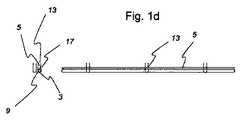
図1aは本発明がクレームする巻取装置1を示し、側面図Aおよび正面図Bが示されている。巻取装置1は、上部長手端5および下部長手端7を有するカバー部材3を備える。カバー部材3の長さは、覆われる壁の開口部11の大きさにより調整される。繰り出されたカバー部材3は、部分的にまたは完全に壁の開口部11を任意選択的に覆う。カバー部材3の長手端5および7は付属の補強材を有することができる。下部長手端7は方向転換部材9にしっかりと連結される。方向転換部材9は、コード部分13および13'の間に吊り下げられ、コード部分13および13’が反対方向に移動することで、コード部分の下側の屈曲部にて巻き上げまたは繰り出される。コード13および13'の下側折り返し地点に屈曲部が形成さるので、コード13の移動により方向転換部材9が回転する。コード部分13または13’は垂直軸Zに平行に案内される。下方向への移動時におけるコード13の移動方向は、図1aの矢印Yによって示される。コード13または13’は、連結継ぎ手17にてカバー部材3の上部長手端5に連結される。
Figures 1a to 1d schematically show the operating modes of a first embodiment of a winding device according to the invention.
FIG. 1a shows a winding
図1bおよび1cは、図1a に示す開位置から図1cに示す初期位置へ巻取装置1が徐々に移動する過程を示す。図1a の開位置では、完全に繰り出されたカバー部材3により壁の開口部が完全に覆われている。図1cの初期位置では、カバー部材3は、完全に巻き上げられた状態つまり完全にロールアップされた状態である。初期位置では、壁の開口部は開いており、建物内と建物外の間で空気の自由な流れと換気ができるようになる。
1b and 1c show the process of the gradual movement of the winding
図1bに示す巻取装置1は一部開状態である。カバー部材3は方向転換部材9上で部分的に巻き上げられている。図1bでは、壁の開口部11の下部分のみがカバー部材3により覆われている。上部長手端5は矢印Yが示す移動方向に水平軸(図示無し)に平行に案内される。
The winding
図1aの矢印Yが示す移動方向に上部長手端5が移動する間、方向転換部材9の回転速度が一定に保たれる必要は無い。代わりに、方向転換部材9とカバー部材3によって形成されるロールの直径が大きくなると、回転速度が遅くなる。
While the upper
装置の発明に係わる設計により、方向転換部材の回転速度は、方向転換部材9とカバー部材3によって形成されるロールの直径が変化に応じて自然と調整される。汚れ、しわ、または低温度により直径が変化する際にも回転速度は調整される。
The design according to the invention of the device, the rotational speed of the deflecting element, the diameter of the roll formed by the deflecting
図1cは、方向転換部材9上で完全に巻き上げられたカバー部材3を示す。壁の開口部11は完全に剥き出した状態にある。この状態から始まり、コード13および13’の移動方向は先の移動方向とは反対に案内されることで、巻取装置は図1aに示す開状態に戻ることが可能である。図1cに示す初期位置から図1dに示す位置に巻取装置を切り替えるには、コードの移動方向は維持されず、引き下げコードは引き上げコードに変更される。よって、巻き上げられたカバー部材3と共に方向転換部材9が持ち上げられる。巻取装置が他の開状態にある場合にも、図1dに示す位置へ巻取装置を切り替えることは可能である。例えば、カバー部材3の一部だけが方向転換部材9上で巻き上げられ、巻取装置が図1bに示すような一部開状態の際にも、方向転換部材9が持ち上げられることも可能である。
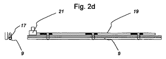
図2aから2dは、本発明による巻取装置1の更なる実施形態の動作モードを概略的に示し、巻取装置1はシャフト19を有する。
FIG. 1 c shows the
FIGS. 2 a to 2 d schematically show the mode of operation of a further embodiment of the winding
図2aは本実施形態の構造を示す。コード13または13’の自由端23および25は、シャフト19上に配置される。シャフトはモータ21により回転駆動され、自由端23および25の両方がシャフト19にしっかりと連結される。作業ロープ27は、第1自由端23の位置でシャフト19に配置される。作業ロープ27をシャフト19から繰り出すことで、コード13が下方向へ移動する。図1a から1dに示す実施形態と同様に、コード13または13’が連結継ぎ手17を介してカバー部材3の上部長手端5に連結される。
FIG. 2a shows the structure of this embodiment. The free ends 23 and 25 of the
図2bと2cは、図1aから1cと同様に、方向転換部材9上でのカバー部材3の巻取りを図示する。
図2bでは、巻取装置1は一部開状態にある。シャフト19は回転状態であり、作業ロープ27は第1自由端23の位置で繰り出される。作業ロープ27は方向転換部材9により延在し、ひいては第2自由端25の位置に配置される。シャフト19の回転方向はモータ21により変えられる。よって、作業ロープ27は、第1自由端23の位置に再配置される。 作業ロープ27の繰り出しに平行して、Y方向(図1aに示す)に沿って上部長手端5が移動する。よって、カバー部材3が方向転換部材9の周りで巻き上げられる。
2b and 2c illustrate the winding of the
In FIG. 2b, the winding
図2cおよび2dは、図1cおよび1dと同様に、方向転換部材9の上昇を図示する。方向転換部材9は、モータ21からシャフト19へ伝達される動力により上昇される。
コード13または13’がシャフトに連結しており、図2cに示すコード13は完全に繰り出されているので、コード13が図2cに示される状態から更に撓むことはできない。同じ方向へシャフトが更に回転しても、コード13が更に下がることはない。代わりに、コード13がシャフト周りで巻き上げられ、結果、二つのコード13、13’が上昇する際に、巻き上げられたカバー部材3が上昇する。
2c and 2d illustrate the raising of the turning
Since the
図2eは本発明による実施形態を示し、コード13、13’の案内部材を更に有する。コード13、13’は、コード13、13’の最下側点に連結された張力部材30により、特に安定する。 これにより、巻取装置1やカバー部材3が風や吸引力にさらされる場合も、巻取装置1やカバー部材3は、コード13、13’によって安定する。
FIG. 2e shows an embodiment according to the invention, which further comprises guide members for
図2fは、本発明による巻取装置1の他の実施形態の動作モードを示し、巻取装置1はシャフト19を有する。コード13または13’の自由端23および25はシャフト19上に取り付けられる。シャフトはモータ21により回転駆動され、自由端23および25の両方がシャフト19にしっかりと連結される。作業ロープ27は第1自由端23の位置でシャフト19に連結される。作業ロープ27をシャフト19から繰り出すことで、コード13が下方向へ移動する。図1bと1cと同様に、図2bと2cは方向転換部材9周りでのカバー部材3の巻取りを示す。
FIG. 2 f shows the operating mode of another embodiment of the winding
本実施形態で、コード13、13’はV字形状で設置される。このことからも明らかな通り、 平行に配設するのは実用的ではあるが、コード13、13’は必ずしも平行にのびる必要はなく、他の形状で配設されてもよい。
In the present embodiment, the
図2gは、図2eと2fの発明に適合した巻取装置の実施形態を示し、コードの下側の屈曲部に配設される張力部材30’によりコード13、13’が案内される。
図3aから3dは、本発明による巻取装置1の他の実施形態の動作モードを概略的に示す。巻取装置1はケーブルプルを有する。
FIG. 2g shows an embodiment of the winding device adapted to the invention of FIGS. 2e and 2f, in which the
Figures 3a to 3d schematically show the operating modes of another embodiment of the winding
本実施形態では、方向転換部材9周りでのカバー部材3の巻取りや繰り出し、および方向転換部材9の昇降はケーブルプル機構により制御される。ケーブルプル機構は、複数の方向転換ロール28と1つのケーブルプル29を有し、コード13または13’が方向転換ロール28により案内される。図示される実施形態では、下方向へ移動するコード13の一部が半時計周りに270度の角度で左側方向転換ロール28により向きが変えられながら下方向へ移動し続ける。
In the present embodiment, the
上方向へ移動するコード13’の一部も左側方向転換ロール28により案内されるが、コード13’の一部はコード13の一部が移動し続ける方向と反対方向に移動し続ける。右側に位置する方向転換ロール28は引き下げコードと引き上げコードとを変える。これは、図3cに示す操作状態から図3dに示す操作状態への移行に必要である。
A part of the
ケーブルプル機構を用いる実施形態に関しては、様々な変形例が実際の使用上考えられる。変形例は、方向転換ロール28およびケーブルプル29の数や位置により様々である。ケーブルプル29は、手動タイプでもモータ駆動タイプのいずれでもよい。
Regarding the embodiment using the cable pull mechanism, various modifications are conceivable in actual use. Variations vary depending on the number and position of the
図3bおよび3cは、図1bおよび1c、図2bおよび2c同様に、開位置から初期位置へ巻取装置1が移行する連続過程を図示する。
図3cおよび3dは、図1cおよび1d、図2cおよび2d同様に、方向転換部材9の上昇を図示する。
3b and 3c illustrate a continuous process in which the winding
3c and 3d illustrate the raising of the turning
図4aから4dは、本発明に係わる巻取装置の他の実施形態の動作モードを概略的に示し、第1コード13、13'と第2コード31を有する。
図2aから2dに既に図示されているとおり、第1コード13または13'の自由端23および25はシャフト19にしっかりと連結される。装置はさらに第2コード31を有し、第1自由端でシャフト19にしっかりと連結され、第2自由端でカバー部材3の上部長手端5にしっかりと連結される。
FIGS. 4 a to 4 d schematically show the operation mode of another embodiment of the winding device according to the invention, which has a
As already illustrated in FIGS. 2 a to 2 d, the free ends 23 and 25 of the
本発明に係わる本実施形態において、図1aから1dに図示される連結継ぎ手17は省略できる。
図4bおよび4cは、図1bおよび1c、図2bおよび2c、図3bおよび3c同様に、開位置から初期位置へ巻取装置1が移行する連続過程を図示する。
In this embodiment according to the present invention, the coupling joint 17 illustrated in FIGS. 1a to 1d can be omitted.
4b and 4c illustrate a continuous process in which the winding
図4cおよび4dは、図1bおよび1c、図2bおよび2c、図3bおよび3c同様に、方向転換部材9の上昇を図示する。
図5aから5dは本発明に係わる巻取装置1の他の実施形態の動作モードを概略的に示し、第1コード13、13'と第2コード31を有する。第1コード13'の第1自由端23はシャフト19にしっかりと連結され、第1コード13の第2自由端25は上部長手端5としっかりと連結される。第2コード31の第1自由端はシャフト19にしっかりと連結され、第2コード31の第2自由端は上部長手端5としっかりと連結される。
図5bおよび5cは、先の図面のbやcと同様に、開位置から初期位置へ巻取装置1が移行する連続過程を図示する。
FIGS. 4c and 4d illustrate the raising of the turning
FIGS. 5 a to 5 d schematically show the operation mode of another embodiment of the winding
5b and 5c illustrate a continuous process in which the winding
図5cおよび5dは、先の図面のcやdと同様に、方向転換部材9の上昇を図示する。
このとき、方向転換部材9はかならずしも剛性要素である必要は無いことが強調されなければならない。さらに、方向転換部材9は、本発明に係わる巻取装置1とは必ずしも別体でなくてもよい。例えば、方向転換部材9は、布地の下の縁や下端で形成されてもよい。布地の縁や下端と巻取り可能なコードの連携により、縁や端は一定方向に回転され、結果、緩んだ巻きが巻き取られたりまたは繰り出されたりする。
Figures 5c and 5d illustrate the raising of the turning
At this time, it must be emphasized that the
図6は、本発明に係わる巻取装置1の実施形態の使用を示し、一部途切れた開口部を覆う。巻取装置1のカバー部材3は、ドアや何かで遮断されてもよい。カバー部材3の幅に渡って配置される複数のコード13、13’を用いることで、カバー部材3は遮断部50を見せてしまうが、図1および2に記載される機能は、1つのドライブで実現可能である。
他の参照符号の機能については、図1から5の特徴事項を記載する際に既に説明されているので、詳細な説明はここでは省略する。
FIG. 6 shows the use of an embodiment of the winding
The functions of the other reference numerals have already been described when describing the features of FIGS. 1 to 5, and thus detailed description thereof is omitted here.
図7aから7dは、本発明に係わる巻取装置1の異なる複数の実施形態を概略的に示し、コードの長さが最適化されている。
図7aと7bに示す実施形態では、コード13、13'の両端は、昇降ユニットを介して、とりわけシャフト19(図7b)またはケーブルプル29(図7a)に連結される。所要の機能を実現するために、コード13、13’の望ましい長さは、カバー部材3の高さHの3倍の長さと、完全に繰り出されたカバー部材3の上部長手端5と昇降ユニット間の距離Mの2倍の長さの和におよそ相当する。
Figures 7a to 7d schematically show different embodiments of the winding
In the embodiment shown in FIGS. 7a and 7b, the ends of the
図7cは、1つの実施形態を示し、コードの一端は、昇降ユニットのシャフト19に連結され、コードの他端は、カバー部材3の上部長手端5に連結される。よって、コード13、13’はカバー部材を囲う。本実施形態において、コードの理想的な長さとしては、カバー部材3の高さHの2倍の長さと完全に繰り出されたカバー部材3の上部長手端5と昇降ユニット間の距離Mの長さの和におよそ相当すれば十分である。
FIG. 7 c shows one embodiment, where one end of the cord is connected to the
図7dに示す実施形態は、第2コード31の望ましい長さを示す。第2コードの一端は昇降ユニットのシャフト19に連結され、他端がカバー部材3の上部長手端5に連結される。コード31は、カバー部材を囲まないが上部長手端5に直接連結される。コード31の望ましい長さは、カバー部材3の高さHの長さと完全に繰り出されたカバー部材3の上部長手端5と昇降ユニット間の距離Mの長さの和におよそ相当する。
The embodiment shown in FIG. 7 d shows the desired length of the
図7aから7dはすべて、作業ロープ27の効果的な長さを示す。図に示す位置において、カバー部材3は完全に繰り出された状態であり、開口部を覆っている。この位置において、延伸した作業ロープ27の長さ(ケーブルプル機構の場合)、または巻き上げられた作業ロープ27の長さ(シャフトの場合)は、カバー部材3の高さHにおよそ相当する。
Figures 7a to 7d all show the effective length of the
本発明は、好ましい実施形態に関して記載されている。専門家による添付のクレームの保護範囲に属する変更や変形もまた本発明から逸脱することなく行うことができる。
参照番号の一覧
1 巻取装置
3 カバー部材
5 上部長手端
7 下部長手端
9 方向転換部材
11 壁の開口部
13 下方向に移動するコード
13’ 上方向に移動するコード
17 コードと上部長手端間の連結継ぎ手
19 シャフト
21 モータ
23 第1コードの第1自由端
25 第1コードの第2自由端
27 作業ロープ
28 方向転換ロール
29 ケーブルプル
30 張力装置
30’ 張力装置
31 第2コード
50 遮断部
A 巻取装置の側面図
B 巻取装置の正面図
X 第1垂直移動方向
Y 第2垂直移動方向
Z 垂直軸
The invention has been described with reference to the preferred embodiments. Changes and modifications within the scope of protection of the appended claims by the expert may also be made without departing from the invention.
List of
Claims (20)
前記カバー部材(3)が、上部長手端および下部長手端(5,7)を有し、
前記カバー部材(3)の前記下部長手端(7)が前記方向転換部材(9)に連結されるか、または該カバー部材(3)の該下部長手端(7)が該方向転換部材(9)を形成し、該カバー部材(3)が、水平軸周りの該方向転換部材(9)の回転、または水平軸周りの該下部長手端(7)の回転により、巻き上げられることが可能であり、
前記昇降ユニットが、少なくとも1つのコード(13,13’)を有し、該コードの少なくとも1つの自由端(23,25)が該昇降ユニットに連結され、該コード(13,13’)が、前記カバー部材(3)を囲うように設けられ、前記方向転換部材(9)または該カバー部材(3)の前記下部長手端(7)が該コードの屈曲部で案内され、かつ
前記方向転換部材(9)または前記カバー部材(3)の前記下部長手端(7)が、前記少なくとも1つのコード(13,13’)の動きにより二つの反対回転移動方向に案内されることが可能であり、
前記少なくとも1つのコード(13,13’)の引き下げまたは引き上げにより、前記上部長手端(5)が、上昇または降下する、巻取装置。 A winding device (1) comprising a cover member (3) that can be rolled up, a direction changing member (9), and at least one lifting unit, covering a wall opening (11) or window,
The cover member (3) has an upper longitudinal end and a lower longitudinal end (5, 7);
The lower longitudinal end (7) of the cover member (3) is connected to the direction changing member (9), or the lower longitudinal end (7) of the cover member (3) is the direction changing member. (9) is formed, and the cover member (3) is wound up by rotation of the direction changing member (9) around the horizontal axis or rotation of the lower longitudinal end (7) around the horizontal axis. Is possible,
The lifting unit has at least one cord (13, 13 ′), at least one free end (23, 25) of the cord is connected to the lifting unit, and the cord (13, 13 ′) The direction change member (9) or the lower longitudinal end (7) of the cover member (3) is guided by a bent portion of the cord, and is provided so as to surround the cover member (3). The lower longitudinal end (7) of the member (9) or the cover member (3) can be guided in two opposite rotational movement directions by the movement of the at least one cord (13, 13 '). Yes,
Winding device in which the upper longitudinal end (5) is raised or lowered by lowering or raising the at least one cord (13, 13 ').
前記昇降ユニットが、シャフト(19)またはケーブルプルである、巻取装置。 The winding device according to claim 1,
Winding device, wherein the lifting unit is a shaft (19) or a cable pull.
水平軸周りの前記シャフト(19)の回転、または前記ケーブルプルの水平移動を可能とするドライブユニット(21)を有する、巻取装置。 The winding device according to claim 2,
Winding device comprising a drive unit (21) allowing rotation of the shaft (19) about a horizontal axis or horizontal movement of the cable pull.
前記ドライブユニットがモータ(21)である、巻取装置。 The winding device according to claim 3,
The winding device, wherein the drive unit is a motor (21).
少なくとも1つの第1コード(13,13’)および少なくとも1つの第2コード(31)を有し、該第1コード(13,13’)が、互いに反対方向である2つの移動方向に、前記方向転換部材(9)または前記カバー部材(3)の前記下部長手端(7)を案内し、
前記第1コード(13,13’)が、前記カバー部材(3)もしくは該カバー部材(3)の前記下部長手端(7)を巻き取るためのものか、または該第1コード(13,13’)が、該カバー部材(3)もしくは該カバー部材(3)の該下部長手端(7)を巻き取り、かつ該巻上げられたカバー部材(3)を上昇または下降するためのものであり、かつ
前記第2コード(31)が、前記カバー部材(3)の前記上部長手端(5)を上昇、または下降するためのものである、巻取装置。 The winding device according to any one of claims 1 to 4,
Having at least one first cord (13, 13 ′) and at least one second cord (31), wherein the first cord (13, 13 ′) is in two moving directions opposite to each other, Guiding the lower longitudinal end (7) of the direction changing member (9) or the cover member (3);
The first cord (13, 13 ') is for winding the cover member (3) or the lower longitudinal end (7) of the cover member (3), or the first cord (13, 13') 13 ') is for winding up the cover member (3) or the lower longitudinal end (7) of the cover member (3) and raising or lowering the wound cover member (3). There is a winding device in which the second cord (31) is for raising or lowering the upper longitudinal end (5) of the cover member (3).
前記第1コード(13,13’)の両方の自由端(23、25)が前記昇降ユニットに連結され、かつ
前記第2コード(31)が、その第1自由端を介して前記昇降ユニットに連結され、かつその第2自由端を介して前記カバー部材(3)の前記上部長手端(5)に連結される、巻取装置。 The winding device according to claim 5,
Both free ends (23, 25) of the first cord (13, 13 ′) are connected to the lifting unit, and the second cord (31) is connected to the lifting unit via the first free end. Winding device connected and connected to the upper longitudinal end (5) of the cover member (3) via its second free end.
前記第1コード(13,13’)が、その第1自由端(23)を介して前記昇降ユニットに連結され、かつその第2自由端(25)を介して前記カバー部材(3)の前記上部長手端(5)に連結され、かつ
前記第2コード(31)が、その第1自由端を介して前記昇降ユニットに連結され、かつその第2自由端を介して前記カバー部材(3)の前記上部長手端(5)に連結される、巻取装置。 The winding device according to claim 5,
The first cord (13, 13 ′) is connected to the elevating unit via its first free end (23), and the cover member (3) via the second free end (25). The upper cord is connected to the upper longitudinal end (5), and the second cord (31) is connected to the elevating unit via the first free end, and the cover member (3 ) Of the upper longitudinal end (5).
前記方向転換部材(9)または該カバー部材(3)の前記下部長手端(7)が回転することで、前記カバー部材(3)が、該方向転換部材(9)または該カバー部材(3)の該下部長手端(7)上で巻き上げられることが可能である、巻取装置。 The winding device according to any one of claims 1 to 4 ,
When the lower longitudinal end (7) of the direction changing member (9) or the cover member (3) rotates, the cover member (3) becomes the direction changing member (9) or the cover member (3). ) Of the lower longitudinal end (7) of the winding device.
前記方向転換部材(9)または該カバー部材(3)の前記下部長手端(7)が回転することで、前記カバー部材(3)が、該方向転換部材(9)または該カバー部材(3)の該下部長手端(7)上で巻き上げられることが可能である、巻取装置。 When the lower longitudinal end (7) of the direction changing member (9) or the cover member (3) rotates, the cover member (3) becomes the direction changing member (9) or the cover member (3). ) Of the lower longitudinal end (7) of the winding device.
前記少なくとも1つの第1コード(13,13’)及び前記少なくとも1つの第2コード(31)を引き上げることで、前記カバー部材(3)は上昇可能である、請求項9記載の巻取装置。 Comprising at least one first code (13, 13 ') and at least one second code (31),
Before Symbol By pulling the at least one first code (13, 13 ') and the at least one second code (31), said cover member (3) can be increased, the winding apparatus according to claim 9, wherein .
前記少なくとも1つのコード(13,13’)が張力装置(30,30’)を介して案内される、巻取装置。 The winding device according to any one of claims 1 to 10 ,
Winding device in which the at least one cord (13, 13 ') is guided via a tension device (30, 30').
前記少なくとも1つのコード(13,13’)の長さが、前記カバー部材(3)の高さ(H)の3倍の長さと完全に繰り出された該カバー部材(3)の前記上部長手端(5)と前記昇降ユニット間の距離(M)の2倍の長さの和におよそ相当し、または、該少なくとも1つのコード(13,13’)の長さが、該カバー部材(3)の高さ(H)の2倍の長さと該完全に繰り出されたカバー部材(3)の該上部長手端(5)と該昇降ユニット間の距離(M)の長さの和におよそ相当する、巻取装置。 The winding device according to any one of claims 1 to 11,
The length of the at least one cord (13, 13 ') is three times the height (H) of the cover member (3) and the upper longitudinal direction of the cover member (3) fully extended. Approximately equivalent to the sum of the lengths twice the distance (M) between the end (5) and the lifting unit, or the length of the at least one cord (13, 13 ') is the cover member (3 About the sum of the length (H) twice the height (H) and the distance (M) between the upper longitudinal end (5) of the fully extended cover member (3) and the lifting unit. Corresponding winding device.
少なくとも1つの第2コード(31)を備え、
前記少なくとも1つの第2コード(31)の長さが、前記カバー部材(3)の高さ(H)と前記完全に繰り出されたカバー部材(3)の前記上部長手端(5)と前記昇降ユニット間の距離(M)の和におよそ相当する、巻取装置。 The winding device according to claim 6 or 7 ,
Comprising at least one second cord (31),
The length of the at least one second cord (31) is the height (H) of the cover member (3), the upper longitudinal end (5) of the fully extended cover member (3), and the A winding device approximately corresponding to the sum of distances (M) between the lifting units.
前記コード(13,31)の作業ロープ(27)の長さが、前記完全に繰り出されたカバー部材(3)の高さ(H)におよそ相当する、巻取装置。 The winding device according to any one of claims 1 to 13,
The winding device, wherein the length of the work rope (27) of the cord (13, 31) corresponds approximately to the height (H) of the completely extended cover member (3).
前記コード(13,13’)が前記カバー部材(3)の前記上部長手端(5)に連結される、巻取装置。 The winding device according to any one of claims 1 to 5 ,
The winding device, wherein the cord (13, 13 ') is connected to the upper longitudinal end (5) of the cover member (3).
前記カバー部材(3)が、上部長手端および下部長手端(5,7)を有し、かつ
前記カバー部材(3)の前記下部長手端(7)が、前記方向転換部材(9)に連結されるか、または前記方向転換部材(9)を形成し、
前記昇降ユニットが少なくとも1つのコード(13,13’)を有し、少なくとも1つの自由端(23,25)が該昇降ユニットに連結され、前記方向転換部材(9)または前記カバー部材(3)の前記下部長手端(7)が該少なくとも1つのコード(13,13’)の屈曲部で案内されるように、該コード(13,13’)が前記カバー部材(3)を囲い、該方向転換部材(9)または該下部長手端(7)が前記少なくとも1つのコードの動きにより二つの反対の回転方向に回転移動可能であり、該方向転換部材(9)または該下部長手端(7)が回転することで、該カバー部材(3)が、該方向転換部材(9)または該下部長手端(7)上で巻かれ、
前記少なくとも1つのコード(13,13’)の引き下げまたは引き上げにより、前記上部長手端(5)が、上昇または降下する、方法。 A winding member (1) comprising a cover member (3) that can be rolled up, a direction changing member (9), and at least one lifting unit, and covering a wall opening (11) or window;
The cover member (3) has an upper longitudinal end and a lower longitudinal end (5, 7), and the lower longitudinal end (7) of the cover member (3) is the direction changing member (9). ) Or form the redirecting member (9),
The elevating unit has at least one cord (13, 13 '), and at least one free end (23, 25) is connected to the elevating unit, and the direction changing member (9) or the cover member (3) The cord (13, 13 ') surrounds the cover member (3) so that the lower longitudinal end (7) of the at least one cord (13, 13') is guided by the bent portion of the at least one cord (13, 13 ') a redirecting member (9) or lower director hand end (7) is rotatably moved in the direction of rotation of the two opposite the motion of said at least one code, the redirecting member (9) or the lower longitudinal By rotating the end (7), the cover member (3) is wound on the turning member (9) or the lower longitudinal end (7),
Method wherein the upper longitudinal end (5) is raised or lowered by lowering or raising the at least one cord (13, 13 ').
前記方向転換部材(9)または前記下部長手端(7)が一方の移動方向に回転することで、前記カバー部材(3)が、該方向転換部材(9)または該下部長手端(7)上で巻かれ、少なくとも1つのコード(13、13‘)を引き上げることで該カバー部材(3)が持ち上げられる、方法。 The method according to claim 16, comprising:
When the direction changing member (9) or the lower longitudinal end (7) rotates in one moving direction, the cover member (3) becomes the direction changing member (9) or the lower longitudinal end (7). ) The cover member (3) is lifted by winding up and pulling up at least one cord (13, 13 ').
前記カバー部材(3)の巻取りかつ繰り出しが、前記方向転換部材(9)または該カバー部材(3)の前記下部長手端(7)上のみで行われる、方法。 The method according to claim 16 or 17,
The method wherein winding and unwinding of the cover member (3) is performed only on the direction changing member (9) or the lower longitudinal end (7) of the cover member (3).
前記少なくとも1つのコード(13,13’)を引き下げまたは引き上げることにより、前記カバー部材(3)を巻き上げた後に、更にコード(13,13’)を引き上げることにより、完全に巻き上げられた前記カバー部材(3)を上昇させる方法。 19. The method according to any one of claims 16 to 18, comprising
The cover member fully wound up by further pulling up the cord (13, 13 ') after the cover member (3) is wound up by pulling down or pulling up the at least one cord (13, 13') (3) The method of raising .
前記巻取装置(1)が少なくとも1つの第1コード(13,13’)及び少なくとも1つの第2コード(31)を有し、該第2コード(31)の第1自由端が、前記昇降ユニットに連結され、該第2コード(31)の第2自由端が、前記カバー部材(3)の前記上部長手端(5)に連結され、
前記少なくとも1つの第1コード(13,13’)及び前記少なくとも1つの第2コード(31)を引き下げまたは引き上げることにより、前記カバー部材(3)を巻き上げた後に、更に前記少なくとも1つの第1コード(13,13’)及び前記少なくとも1つの第2コード(31)を引き上げることにより、完全に巻き上げられた前記カバー部材(3)を上昇させる、方法。 19. The method according to any one of claims 16 to 18 , comprising
The winding device (1) has at least one first cord (13, 13 ′) and at least one second cord (31), and the first free end of the second cord (31) is moved up and down. Connected to the unit, the second free end of the second cord (31) is connected to the upper longitudinal end (5) of the cover member (3),
After the cover member (3) is wound up by lowering or pulling up the at least one first cord (13, 13 ') and the at least one second cord (31), the at least one first cord (13, 13 ′) and a method of raising the completely wound up cover member (3) by pulling up the at least one second cord (31) .
Applications Claiming Priority (3)
| Application Number | Priority Date | Filing Date | Title |
|---|---|---|---|
| DE202009005007.6 | 2009-07-09 | ||
| DE202009005007U DE202009005007U1 (en) | 2009-07-09 | 2009-07-09 | Winding device for covering wall openings or windows |
| PCT/EP2010/004082 WO2011003576A2 (en) | 2009-07-09 | 2010-07-06 | Winding device for covering wall openings or windows |
Publications (3)
| Publication Number | Publication Date |
|---|---|
| JP2012532260A JP2012532260A (en) | 2012-12-13 |
| JP2012532260A5 JP2012532260A5 (en) | 2014-11-06 |
| JP5852957B2 true JP5852957B2 (en) | 2016-02-03 |
Family
ID=43304817
Family Applications (1)
| Application Number | Title | Priority Date | Filing Date |
|---|---|---|---|
| JP2012518810A Expired - Fee Related JP5852957B2 (en) | 2009-07-09 | 2010-07-06 | Winding device for covering a wall opening or window |
Country Status (10)
| Country | Link |
|---|---|
| US (1) | US8820387B2 (en) |
| EP (1) | EP2452034B1 (en) |
| JP (1) | JP5852957B2 (en) |
| KR (1) | KR101762976B1 (en) |
| CN (1) | CN102472080B (en) |
| CA (1) | CA2767466C (en) |
| DE (1) | DE202009005007U1 (en) |
| DK (1) | DK2452034T3 (en) |
| EA (1) | EA026010B1 (en) |
| WO (1) | WO2011003576A2 (en) |
Families Citing this family (8)
| Publication number | Priority date | Publication date | Assignee | Title |
|---|---|---|---|---|
| DE202009005007U1 (en) * | 2009-07-09 | 2010-12-16 | Zettl, Horst | Winding device for covering wall openings or windows |
| IL220779A (en) * | 2012-07-05 | 2016-08-31 | Holis Metal Ind Ltd | Multi-function blind |
| DE202014105368U1 (en) * | 2014-11-10 | 2014-12-01 | Lock Antriebstechnik Gmbh | Winding device for covering building openings |
| CN104632062B (en) * | 2015-01-30 | 2016-05-25 | 福建固美金属有限公司 | A kind of intelligent tow-way shutter window |
| US11134652B2 (en) | 2016-01-14 | 2021-10-05 | Shady Lane Curtains, Llc | Retractable curtain for livestock structures |
| US11534983B2 (en) | 2016-01-14 | 2022-12-27 | Shady Lane Curtains, Llc | Method of making a barn curtain with joined panels |
| KR102092614B1 (en) | 2018-10-22 | 2020-03-24 | 휴켐스주식회사 | Mass production method of 4,4'-oxydianiline from 1,4-diiodobenzene |
| CN113885291B (en) * | 2021-10-23 | 2022-05-13 | 江苏舜合物联网科技有限公司 | Mechanism for realizing lifting and collecting of curtain by spring |
Family Cites Families (23)
| Publication number | Priority date | Publication date | Assignee | Title |
|---|---|---|---|---|
| US257826A (en) * | 1882-05-09 | Curtain-fixture | ||
| US119983A (en) * | 1871-10-17 | Improvement in curtain-fixtures | ||
| US75037A (en) * | 1868-03-03 | Improved window-shade | ||
| US112814A (en) * | 1871-03-21 | Improvement in curtain-fixtures | ||
| US108752A (en) * | 1870-11-01 | Improvement in curtain-fixtures | ||
| US1181120A (en) * | 1915-07-06 | 1916-05-02 | Walter C Douthitt | Blind or shade. |
| US1225060A (en) * | 1916-01-28 | 1917-05-08 | Clyde W Warren | Curtain-anchoring device. |
| US1464412A (en) * | 1921-05-16 | 1923-08-07 | Dillon Frank | Shade roller |
| US1473517A (en) * | 1922-02-06 | 1923-11-06 | Wilbert M Richards | Roller-curtain guiding and locking device |
| US1870920A (en) * | 1929-09-16 | 1932-08-09 | Thomas E Mcnulty | Curtain guide |
| US2582276A (en) | 1949-05-16 | 1952-01-15 | Frank M Powers | Porch shade |
| FR2563860A1 (en) | 1984-05-03 | 1985-11-08 | Farnier & Penin | Motorised blind with positively controlled winding and unwinding |
| JPH01162587U (en) * | 1988-04-28 | 1989-11-13 | ||
| US5819835A (en) * | 1995-09-20 | 1998-10-13 | Draper Shade & Screen Co., Inc. | Roll-up divider |
| US5785105A (en) * | 1995-11-13 | 1998-07-28 | Crider; Grant W. | Sealable curtain |
| DE29815953U1 (en) | 1998-05-28 | 1998-11-19 | Arntjen, Gerd, 26180 Rastede | Ventilation device for arrangement in a wall area of a barn building |
| US6138739A (en) * | 1999-01-15 | 2000-10-31 | Grant W. Crider | Portal covering |
| DE20117865U1 (en) | 2001-11-06 | 2002-02-28 | AGROTEL GmbH, 94152 Neuhaus | closure device |
| JP3850301B2 (en) * | 2002-01-24 | 2006-11-29 | 株式会社ニチベイ | Roll screen |
| DE20214076U1 (en) | 2002-09-10 | 2003-05-08 | Bvba Vervaeke, Ruiselede | Vertical roller blind system for protection from sun, wind or frost. |
| US6860312B2 (en) * | 2002-09-27 | 2005-03-01 | Ren Judkins | Roll-up shade with cord capture |
| GB2431190B (en) * | 2005-10-13 | 2010-02-24 | John Benjamin Slater | Adjustable screen |
| DE202009005007U1 (en) * | 2009-07-09 | 2010-12-16 | Zettl, Horst | Winding device for covering wall openings or windows |
-
2009
- 2009-07-09 DE DE202009005007U patent/DE202009005007U1/en not_active Expired - Lifetime
-
2010
- 2010-07-06 EA EA201200099A patent/EA026010B1/en not_active IP Right Cessation
- 2010-07-06 KR KR1020127003405A patent/KR101762976B1/en active IP Right Grant
- 2010-07-06 CA CA2767466A patent/CA2767466C/en active Active
- 2010-07-06 US US13/381,782 patent/US8820387B2/en active Active
- 2010-07-06 JP JP2012518810A patent/JP5852957B2/en not_active Expired - Fee Related
- 2010-07-06 EP EP10743015.9A patent/EP2452034B1/en not_active Not-in-force
- 2010-07-06 DK DK10743015.9T patent/DK2452034T3/en active
- 2010-07-06 CN CN201080030772.XA patent/CN102472080B/en not_active Expired - Fee Related
- 2010-07-06 WO PCT/EP2010/004082 patent/WO2011003576A2/en active Application Filing
Also Published As
| Publication number | Publication date |
|---|---|
| WO2011003576A3 (en) | 2011-11-24 |
| KR101762976B1 (en) | 2017-07-28 |
| DE202009005007U1 (en) | 2010-12-16 |
| US20120138243A1 (en) | 2012-06-07 |
| CA2767466A1 (en) | 2011-01-13 |
| CN102472080B (en) | 2015-12-09 |
| CA2767466C (en) | 2014-01-21 |
| EA026010B1 (en) | 2017-02-28 |
| WO2011003576A2 (en) | 2011-01-13 |
| DK2452034T3 (en) | 2018-06-18 |
| KR20120039706A (en) | 2012-04-25 |
| CN102472080A (en) | 2012-05-23 |
| US8820387B2 (en) | 2014-09-02 |
| EA201200099A1 (en) | 2012-08-30 |
| EP2452034B1 (en) | 2018-03-14 |
| EP2452034A2 (en) | 2012-05-16 |
| JP2012532260A (en) | 2012-12-13 |
Similar Documents
| Publication | Publication Date | Title |
|---|---|---|
| JP5852957B2 (en) | Winding device for covering a wall opening or window | |
| JP2012532260A5 (en) | ||
| EP3054076A1 (en) | Brake device for lift shades | |
| US20100294438A1 (en) | Roman shade system | |
| JP6195582B2 (en) | Screen door with blind function | |
| CN109906302B (en) | Adjustable spring system and method for roller blinds | |
| US20220065040A1 (en) | Semi-rigid chain assembly | |
| KR20130009939A (en) | Multi-functional dual roll blind with lower roll screen | |
| JP5238392B2 (en) | Roller blind screen lifting device | |
| EP2167762A2 (en) | Covering system | |
| KR101514016B1 (en) | Canopy type awning | |
| KR200469122Y1 (en) | Tention control apparatus for Electric motion type blind system | |
| US10822804B2 (en) | Retractable awning | |
| KR20110085337A (en) | A venetian blinds | |
| KR200476979Y1 (en) | Shading device having structure for preventing screen sagging | |
| KR200482821Y1 (en) | electromotion type roll blind with tension device | |
| KR100500716B1 (en) | Both course be coiled roll blind | |
| KR101021325B1 (en) | Manual typed screen blind | |
| KR101347376B1 (en) | Inner-roof cover installing structure of vinyl house | |
| JP4409400B2 (en) | Winding device and horizontal curtain with winding device | |
| KR20200143932A (en) | Electric Roll blind | |
| KR101182603B1 (en) | Return apparatus of roll screen | |
| KR102710160B1 (en) | Screen Device | |
| KR102669666B1 (en) | Motorized roll blinds for vertical, horizontal and inclined installation | |
| EP2440734A1 (en) | A shade device |
Legal Events
| Date | Code | Title | Description |
|---|---|---|---|
| A711 | Notification of change in applicant |
Free format text: JAPANESE INTERMEDIATE CODE: A711 Effective date: 20130305 |
|
| A521 | Request for written amendment filed |
Free format text: JAPANESE INTERMEDIATE CODE: A821 Effective date: 20130305 |
|
| A521 | Request for written amendment filed |
Free format text: JAPANESE INTERMEDIATE CODE: A523 Effective date: 20130704 |
|
| A621 | Written request for application examination |
Free format text: JAPANESE INTERMEDIATE CODE: A621 Effective date: 20130704 |
|
| A977 | Report on retrieval |
Free format text: JAPANESE INTERMEDIATE CODE: A971007 Effective date: 20140410 |
|
| A131 | Notification of reasons for refusal |
Free format text: JAPANESE INTERMEDIATE CODE: A131 Effective date: 20140513 |
|
| A601 | Written request for extension of time |
Free format text: JAPANESE INTERMEDIATE CODE: A601 Effective date: 20140813 |
|
| A602 | Written permission of extension of time |
Free format text: JAPANESE INTERMEDIATE CODE: A602 Effective date: 20140820 |
|
| A524 | Written submission of copy of amendment under article 19 pct |
Free format text: JAPANESE INTERMEDIATE CODE: A524 Effective date: 20140912 |
|
| A131 | Notification of reasons for refusal |
Free format text: JAPANESE INTERMEDIATE CODE: A131 Effective date: 20150310 |
|
| A521 | Request for written amendment filed |
Free format text: JAPANESE INTERMEDIATE CODE: A523 Effective date: 20150610 |
|
| TRDD | Decision of grant or rejection written | ||
| A01 | Written decision to grant a patent or to grant a registration (utility model) |
Free format text: JAPANESE INTERMEDIATE CODE: A01 Effective date: 20151110 |
|
| A61 | First payment of annual fees (during grant procedure) |
Free format text: JAPANESE INTERMEDIATE CODE: A61 Effective date: 20151207 |
|
| R150 | Certificate of patent or registration of utility model |
Ref document number: 5852957 Country of ref document: JP Free format text: JAPANESE INTERMEDIATE CODE: R150 |
|
| R250 | Receipt of annual fees |
Free format text: JAPANESE INTERMEDIATE CODE: R250 |
|
| LAPS | Cancellation because of no payment of annual fees |