EP3594174A1 - Dispositif de carbonisation de type flux présentant de propriétés de désinfection et distributeur de boissons doté d'un tel dispositif - Google Patents
Dispositif de carbonisation de type flux présentant de propriétés de désinfection et distributeur de boissons doté d'un tel dispositif Download PDFInfo
- Publication number
- EP3594174A1 EP3594174A1 EP19184191.5A EP19184191A EP3594174A1 EP 3594174 A1 EP3594174 A1 EP 3594174A1 EP 19184191 A EP19184191 A EP 19184191A EP 3594174 A1 EP3594174 A1 EP 3594174A1
- Authority
- EP
- European Patent Office
- Prior art keywords
- pipe
- turbulence
- flow
- approximately
- gas
- Prior art date
- Legal status (The legal status is an assumption and is not a legal conclusion. Google has not performed a legal analysis and makes no representation as to the accuracy of the status listed.)
- Granted
Links
- 235000013361 beverage Nutrition 0.000 title claims abstract description 70
- 238000004659 sterilization and disinfection Methods 0.000 title claims description 8
- CURLTUGMZLYLDI-UHFFFAOYSA-N Carbon dioxide Chemical compound O=C=O CURLTUGMZLYLDI-UHFFFAOYSA-N 0.000 claims abstract description 82
- 229910002092 carbon dioxide Inorganic materials 0.000 claims abstract description 41
- 239000001569 carbon dioxide Substances 0.000 claims abstract description 41
- 239000012530 fluid Substances 0.000 claims abstract description 30
- 238000003763 carbonization Methods 0.000 claims description 57
- 239000007788 liquid Substances 0.000 claims description 45
- 238000011144 upstream manufacturing Methods 0.000 claims description 9
- 238000005496 tempering Methods 0.000 claims description 8
- 238000002347 injection Methods 0.000 claims description 4
- 239000007924 injection Substances 0.000 claims description 4
- 238000010000 carbonizing Methods 0.000 claims 1
- 230000001954 sterilising effect Effects 0.000 abstract description 5
- XLYOFNOQVPJJNP-UHFFFAOYSA-N water Substances O XLYOFNOQVPJJNP-UHFFFAOYSA-N 0.000 description 69
- 244000052616 bacterial pathogen Species 0.000 description 6
- 241000700605 Viruses Species 0.000 description 4
- 239000012459 cleaning agent Substances 0.000 description 4
- 238000001816 cooling Methods 0.000 description 4
- 244000052769 pathogen Species 0.000 description 4
- 241001122767 Theaceae Species 0.000 description 2
- 238000004140 cleaning Methods 0.000 description 2
- 230000001105 regulatory effect Effects 0.000 description 2
- RYGMFSIKBFXOCR-UHFFFAOYSA-N Copper Chemical compound [Cu] RYGMFSIKBFXOCR-UHFFFAOYSA-N 0.000 description 1
- 230000003213 activating effect Effects 0.000 description 1
- 230000004913 activation Effects 0.000 description 1
- 239000004020 conductor Substances 0.000 description 1
- 229910052802 copper Inorganic materials 0.000 description 1
- 239000010949 copper Substances 0.000 description 1
- 230000008878 coupling Effects 0.000 description 1
- 238000010168 coupling process Methods 0.000 description 1
- 238000005859 coupling reaction Methods 0.000 description 1
- 238000010586 diagram Methods 0.000 description 1
- 238000007599 discharging Methods 0.000 description 1
- 238000005553 drilling Methods 0.000 description 1
- 239000011521 glass Substances 0.000 description 1
- CKFGINPQOCXMAZ-UHFFFAOYSA-N methanediol Chemical compound OCO CKFGINPQOCXMAZ-UHFFFAOYSA-N 0.000 description 1
- 238000000034 method Methods 0.000 description 1
- 239000007787 solid Substances 0.000 description 1
Images

Classifications
-
- B—PERFORMING OPERATIONS; TRANSPORTING
- B67—OPENING, CLOSING OR CLEANING BOTTLES, JARS OR SIMILAR CONTAINERS; LIQUID HANDLING
- B67D—DISPENSING, DELIVERING OR TRANSFERRING LIQUIDS, NOT OTHERWISE PROVIDED FOR
- B67D1/00—Apparatus or devices for dispensing beverages on draught
- B67D1/07—Cleaning beverage-dispensing apparatus
-
- B—PERFORMING OPERATIONS; TRANSPORTING
- B67—OPENING, CLOSING OR CLEANING BOTTLES, JARS OR SIMILAR CONTAINERS; LIQUID HANDLING
- B67D—DISPENSING, DELIVERING OR TRANSFERRING LIQUIDS, NOT OTHERWISE PROVIDED FOR
- B67D1/00—Apparatus or devices for dispensing beverages on draught
- B67D1/0042—Details of specific parts of the dispensers
- B67D1/0057—Carbonators
- B67D1/0058—In-line carbonators
-
- B—PERFORMING OPERATIONS; TRANSPORTING
- B67—OPENING, CLOSING OR CLEANING BOTTLES, JARS OR SIMILAR CONTAINERS; LIQUID HANDLING
- B67D—DISPENSING, DELIVERING OR TRANSFERRING LIQUIDS, NOT OTHERWISE PROVIDED FOR
- B67D1/00—Apparatus or devices for dispensing beverages on draught
- B67D1/0042—Details of specific parts of the dispensers
- B67D1/0057—Carbonators
- B67D1/0069—Details
- B67D1/007—Structure of the carbonating chamber
-
- A—HUMAN NECESSITIES
- A47—FURNITURE; DOMESTIC ARTICLES OR APPLIANCES; COFFEE MILLS; SPICE MILLS; SUCTION CLEANERS IN GENERAL
- A47J—KITCHEN EQUIPMENT; COFFEE MILLS; SPICE MILLS; APPARATUS FOR MAKING BEVERAGES
- A47J31/00—Apparatus for making beverages
- A47J31/40—Beverage-making apparatus with dispensing means for adding a measured quantity of ingredients, e.g. coffee, water, sugar, cocoa, milk, tea
- A47J31/407—Beverage-making apparatus with dispensing means for adding a measured quantity of ingredients, e.g. coffee, water, sugar, cocoa, milk, tea with ingredient-containing cartridges; Cartridge-perforating means
-
- A—HUMAN NECESSITIES
- A47—FURNITURE; DOMESTIC ARTICLES OR APPLIANCES; COFFEE MILLS; SPICE MILLS; SUCTION CLEANERS IN GENERAL
- A47J—KITCHEN EQUIPMENT; COFFEE MILLS; SPICE MILLS; APPARATUS FOR MAKING BEVERAGES
- A47J31/00—Apparatus for making beverages
- A47J31/40—Beverage-making apparatus with dispensing means for adding a measured quantity of ingredients, e.g. coffee, water, sugar, cocoa, milk, tea
-
- A—HUMAN NECESSITIES
- A23—FOODS OR FOODSTUFFS; TREATMENT THEREOF, NOT COVERED BY OTHER CLASSES
- A23L—FOODS, FOODSTUFFS, OR NON-ALCOHOLIC BEVERAGES, NOT COVERED BY SUBCLASSES A21D OR A23B-A23J; THEIR PREPARATION OR TREATMENT, e.g. COOKING, MODIFICATION OF NUTRITIVE QUALITIES, PHYSICAL TREATMENT; PRESERVATION OF FOODS OR FOODSTUFFS, IN GENERAL
- A23L2/00—Non-alcoholic beverages; Dry compositions or concentrates therefor; Their preparation
- A23L2/52—Adding ingredients
- A23L2/54—Mixing with gases
-
- A—HUMAN NECESSITIES
- A47—FURNITURE; DOMESTIC ARTICLES OR APPLIANCES; COFFEE MILLS; SPICE MILLS; SUCTION CLEANERS IN GENERAL
- A47J—KITCHEN EQUIPMENT; COFFEE MILLS; SPICE MILLS; APPARATUS FOR MAKING BEVERAGES
- A47J31/00—Apparatus for making beverages
-
- A—HUMAN NECESSITIES
- A47—FURNITURE; DOMESTIC ARTICLES OR APPLIANCES; COFFEE MILLS; SPICE MILLS; SUCTION CLEANERS IN GENERAL
- A47J—KITCHEN EQUIPMENT; COFFEE MILLS; SPICE MILLS; APPARATUS FOR MAKING BEVERAGES
- A47J31/00—Apparatus for making beverages
- A47J31/44—Parts or details or accessories of beverage-making apparatus
- A47J31/46—Dispensing spouts, pumps, drain valves or like liquid transporting devices
-
- A—HUMAN NECESSITIES
- A47—FURNITURE; DOMESTIC ARTICLES OR APPLIANCES; COFFEE MILLS; SPICE MILLS; SUCTION CLEANERS IN GENERAL
- A47J—KITCHEN EQUIPMENT; COFFEE MILLS; SPICE MILLS; APPARATUS FOR MAKING BEVERAGES
- A47J31/00—Apparatus for making beverages
- A47J31/44—Parts or details or accessories of beverage-making apparatus
- A47J31/54—Water boiling vessels in beverage making machines
- A47J31/542—Continuous-flow heaters
-
- A—HUMAN NECESSITIES
- A47—FURNITURE; DOMESTIC ARTICLES OR APPLIANCES; COFFEE MILLS; SPICE MILLS; SUCTION CLEANERS IN GENERAL
- A47J—KITCHEN EQUIPMENT; COFFEE MILLS; SPICE MILLS; APPARATUS FOR MAKING BEVERAGES
- A47J31/00—Apparatus for making beverages
- A47J31/44—Parts or details or accessories of beverage-making apparatus
- A47J31/58—Safety devices
-
- A—HUMAN NECESSITIES
- A61—MEDICAL OR VETERINARY SCIENCE; HYGIENE
- A61L—METHODS OR APPARATUS FOR STERILISING MATERIALS OR OBJECTS IN GENERAL; DISINFECTION, STERILISATION OR DEODORISATION OF AIR; CHEMICAL ASPECTS OF BANDAGES, DRESSINGS, ABSORBENT PADS OR SURGICAL ARTICLES; MATERIALS FOR BANDAGES, DRESSINGS, ABSORBENT PADS OR SURGICAL ARTICLES
- A61L2/00—Methods or apparatus for disinfecting or sterilising materials or objects other than foodstuffs or contact lenses; Accessories therefor
- A61L2/02—Methods or apparatus for disinfecting or sterilising materials or objects other than foodstuffs or contact lenses; Accessories therefor using physical phenomena
- A61L2/04—Heat
-
- B—PERFORMING OPERATIONS; TRANSPORTING
- B01—PHYSICAL OR CHEMICAL PROCESSES OR APPARATUS IN GENERAL
- B01F—MIXING, e.g. DISSOLVING, EMULSIFYING OR DISPERSING
- B01F23/00—Mixing according to the phases to be mixed, e.g. dispersing or emulsifying
- B01F23/20—Mixing gases with liquids
- B01F23/23—Mixing gases with liquids by introducing gases into liquid media, e.g. for producing aerated liquids
- B01F23/236—Mixing gases with liquids by introducing gases into liquid media, e.g. for producing aerated liquids specially adapted for aerating or carbonating beverages
- B01F23/2362—Mixing gases with liquids by introducing gases into liquid media, e.g. for producing aerated liquids specially adapted for aerating or carbonating beverages for aerating or carbonating within receptacles or tanks, e.g. distribution machines
-
- B—PERFORMING OPERATIONS; TRANSPORTING
- B01—PHYSICAL OR CHEMICAL PROCESSES OR APPARATUS IN GENERAL
- B01F—MIXING, e.g. DISSOLVING, EMULSIFYING OR DISPERSING
- B01F25/00—Flow mixers; Mixers for falling materials, e.g. solid particles
- B01F25/40—Static mixers
- B01F25/45—Mixers in which the materials to be mixed are pressed together through orifices or interstitial spaces, e.g. between beads
- B01F25/452—Mixers in which the materials to be mixed are pressed together through orifices or interstitial spaces, e.g. between beads characterised by elements provided with orifices or interstitial spaces
- B01F25/4521—Mixers in which the materials to be mixed are pressed together through orifices or interstitial spaces, e.g. between beads characterised by elements provided with orifices or interstitial spaces the components being pressed through orifices in elements, e.g. flat plates or cylinders, which obstruct the whole diameter of the tube
- B01F25/45211—Mixers in which the materials to be mixed are pressed together through orifices or interstitial spaces, e.g. between beads characterised by elements provided with orifices or interstitial spaces the components being pressed through orifices in elements, e.g. flat plates or cylinders, which obstruct the whole diameter of the tube the elements being cylinders or cones which obstruct the whole diameter of the tube, the flow changing from axial in radial and again in axial
-
- B—PERFORMING OPERATIONS; TRANSPORTING
- B01—PHYSICAL OR CHEMICAL PROCESSES OR APPARATUS IN GENERAL
- B01F—MIXING, e.g. DISSOLVING, EMULSIFYING OR DISPERSING
- B01F35/00—Accessories for mixers; Auxiliary operations or auxiliary devices; Parts or details of general application
- B01F35/10—Maintenance of mixers
- B01F35/145—Washing or cleaning mixers not provided for in other groups in this subclass; Inhibiting build-up of material on machine parts using other means
- B01F35/146—Working under sterile conditions; Sterilizing the mixer or parts thereof
-
- B—PERFORMING OPERATIONS; TRANSPORTING
- B01—PHYSICAL OR CHEMICAL PROCESSES OR APPARATUS IN GENERAL
- B01F—MIXING, e.g. DISSOLVING, EMULSIFYING OR DISPERSING
- B01F35/00—Accessories for mixers; Auxiliary operations or auxiliary devices; Parts or details of general application
- B01F35/75—Discharge mechanisms
- B01F35/754—Discharge mechanisms characterised by the means for discharging the components from the mixer
- B01F35/7547—Discharge mechanisms characterised by the means for discharging the components from the mixer using valves, gates, orifices or openings
-
- B—PERFORMING OPERATIONS; TRANSPORTING
- B08—CLEANING
- B08B—CLEANING IN GENERAL; PREVENTION OF FOULING IN GENERAL
- B08B9/00—Cleaning hollow articles by methods or apparatus specially adapted thereto
- B08B9/02—Cleaning pipes or tubes or systems of pipes or tubes
- B08B9/027—Cleaning the internal surfaces; Removal of blockages
- B08B9/032—Cleaning the internal surfaces; Removal of blockages by the mechanical action of a moving fluid, e.g. by flushing
- B08B9/0321—Cleaning the internal surfaces; Removal of blockages by the mechanical action of a moving fluid, e.g. by flushing using pressurised, pulsating or purging fluid
- B08B9/0328—Cleaning the internal surfaces; Removal of blockages by the mechanical action of a moving fluid, e.g. by flushing using pressurised, pulsating or purging fluid by purging the pipe with a gas or a mixture of gas and liquid
-
- B—PERFORMING OPERATIONS; TRANSPORTING
- B67—OPENING, CLOSING OR CLEANING BOTTLES, JARS OR SIMILAR CONTAINERS; LIQUID HANDLING
- B67D—DISPENSING, DELIVERING OR TRANSFERRING LIQUIDS, NOT OTHERWISE PROVIDED FOR
- B67D1/00—Apparatus or devices for dispensing beverages on draught
- B67D1/0042—Details of specific parts of the dispensers
- B67D1/0057—Carbonators
- B67D1/0069—Details
- B67D1/0071—Carbonating by injecting CO2 in the liquid
-
- B—PERFORMING OPERATIONS; TRANSPORTING
- B67—OPENING, CLOSING OR CLEANING BOTTLES, JARS OR SIMILAR CONTAINERS; LIQUID HANDLING
- B67D—DISPENSING, DELIVERING OR TRANSFERRING LIQUIDS, NOT OTHERWISE PROVIDED FOR
- B67D1/00—Apparatus or devices for dispensing beverages on draught
- B67D1/0042—Details of specific parts of the dispensers
- B67D1/0057—Carbonators
- B67D1/0069—Details
- B67D1/0074—Automatic carbonation control
-
- F—MECHANICAL ENGINEERING; LIGHTING; HEATING; WEAPONS; BLASTING
- F28—HEAT EXCHANGE IN GENERAL
- F28D—HEAT-EXCHANGE APPARATUS, NOT PROVIDED FOR IN ANOTHER SUBCLASS, IN WHICH THE HEAT-EXCHANGE MEDIA DO NOT COME INTO DIRECT CONTACT
- F28D7/00—Heat-exchange apparatus having stationary tubular conduit assemblies for both heat-exchange media, the media being in contact with different sides of a conduit wall
- F28D7/10—Heat-exchange apparatus having stationary tubular conduit assemblies for both heat-exchange media, the media being in contact with different sides of a conduit wall the conduits being arranged one within the other, e.g. concentrically
-
- F—MECHANICAL ENGINEERING; LIGHTING; HEATING; WEAPONS; BLASTING
- F28—HEAT EXCHANGE IN GENERAL
- F28F—DETAILS OF HEAT-EXCHANGE AND HEAT-TRANSFER APPARATUS, OF GENERAL APPLICATION
- F28F13/00—Arrangements for modifying heat-transfer, e.g. increasing, decreasing
- F28F13/06—Arrangements for modifying heat-transfer, e.g. increasing, decreasing by affecting the pattern of flow of the heat-exchange media
- F28F13/12—Arrangements for modifying heat-transfer, e.g. increasing, decreasing by affecting the pattern of flow of the heat-exchange media by creating turbulence, e.g. by stirring, by increasing the force of circulation
-
- B—PERFORMING OPERATIONS; TRANSPORTING
- B01—PHYSICAL OR CHEMICAL PROCESSES OR APPARATUS IN GENERAL
- B01F—MIXING, e.g. DISSOLVING, EMULSIFYING OR DISPERSING
- B01F25/00—Flow mixers; Mixers for falling materials, e.g. solid particles
- B01F2025/91—Direction of flow or arrangement of feed and discharge openings
- B01F2025/916—Turbulent flow, i.e. every point of the flow moves in a random direction and intermixes
-
- B—PERFORMING OPERATIONS; TRANSPORTING
- B01—PHYSICAL OR CHEMICAL PROCESSES OR APPARATUS IN GENERAL
- B01F—MIXING, e.g. DISSOLVING, EMULSIFYING OR DISPERSING
- B01F2215/00—Auxiliary or complementary information in relation with mixing
- B01F2215/04—Technical information in relation with mixing
- B01F2215/0413—Numerical information
- B01F2215/0418—Geometrical information
- B01F2215/0431—Numerical size values, e.g. diameter of a hole or conduit, area, volume, length, width, or ratios thereof
-
- B—PERFORMING OPERATIONS; TRANSPORTING
- B01—PHYSICAL OR CHEMICAL PROCESSES OR APPARATUS IN GENERAL
- B01F—MIXING, e.g. DISSOLVING, EMULSIFYING OR DISPERSING
- B01F23/00—Mixing according to the phases to be mixed, e.g. dispersing or emulsifying
- B01F23/20—Mixing gases with liquids
-
- B—PERFORMING OPERATIONS; TRANSPORTING
- B01—PHYSICAL OR CHEMICAL PROCESSES OR APPARATUS IN GENERAL
- B01F—MIXING, e.g. DISSOLVING, EMULSIFYING OR DISPERSING
- B01F25/00—Flow mixers; Mixers for falling materials, e.g. solid particles
- B01F25/30—Injector mixers
- B01F25/31—Injector mixers in conduits or tubes through which the main component flows
- B01F25/312—Injector mixers in conduits or tubes through which the main component flows with Venturi elements; Details thereof
- B01F25/3122—Injector mixers in conduits or tubes through which the main component flows with Venturi elements; Details thereof the material flowing at a supersonic velocity thereby creating shock waves
-
- B—PERFORMING OPERATIONS; TRANSPORTING
- B67—OPENING, CLOSING OR CLEANING BOTTLES, JARS OR SIMILAR CONTAINERS; LIQUID HANDLING
- B67D—DISPENSING, DELIVERING OR TRANSFERRING LIQUIDS, NOT OTHERWISE PROVIDED FOR
- B67D1/00—Apparatus or devices for dispensing beverages on draught
- B67D1/0042—Details of specific parts of the dispensers
- B67D1/0057—Carbonators
- B67D1/0061—Carbonators with cooling means
-
- B—PERFORMING OPERATIONS; TRANSPORTING
- B67—OPENING, CLOSING OR CLEANING BOTTLES, JARS OR SIMILAR CONTAINERS; LIQUID HANDLING
- B67D—DISPENSING, DELIVERING OR TRANSFERRING LIQUIDS, NOT OTHERWISE PROVIDED FOR
- B67D1/00—Apparatus or devices for dispensing beverages on draught
- B67D2001/0095—Constructional details
- B67D2001/0096—Means for pressurizing liquid
- B67D2001/0097—Means for pressurizing liquid using a pump
-
- B—PERFORMING OPERATIONS; TRANSPORTING
- B67—OPENING, CLOSING OR CLEANING BOTTLES, JARS OR SIMILAR CONTAINERS; LIQUID HANDLING
- B67D—DISPENSING, DELIVERING OR TRANSFERRING LIQUIDS, NOT OTHERWISE PROVIDED FOR
- B67D1/00—Apparatus or devices for dispensing beverages on draught
- B67D2001/0095—Constructional details
- B67D2001/0096—Means for pressurizing liquid
- B67D2001/0098—Means for pressurizing liquid using a gas
-
- B—PERFORMING OPERATIONS; TRANSPORTING
- B67—OPENING, CLOSING OR CLEANING BOTTLES, JARS OR SIMILAR CONTAINERS; LIQUID HANDLING
- B67D—DISPENSING, DELIVERING OR TRANSFERRING LIQUIDS, NOT OTHERWISE PROVIDED FOR
- B67D1/00—Apparatus or devices for dispensing beverages on draught
- B67D1/07—Cleaning beverage-dispensing apparatus
- B67D2001/075—Sanitising or sterilising the apparatus
-
- B—PERFORMING OPERATIONS; TRANSPORTING
- B67—OPENING, CLOSING OR CLEANING BOTTLES, JARS OR SIMILAR CONTAINERS; LIQUID HANDLING
- B67D—DISPENSING, DELIVERING OR TRANSFERRING LIQUIDS, NOT OTHERWISE PROVIDED FOR
- B67D2210/00—Indexing scheme relating to aspects and details of apparatus or devices for dispensing beverages on draught or for controlling flow of liquids under gravity from storage containers for dispensing purposes
- B67D2210/00028—Constructional details
- B67D2210/00047—Piping
- B67D2210/00049—Pipes
- B67D2210/00055—Pipes with turbulent flow generators, e.g. vortices
-
- F—MECHANICAL ENGINEERING; LIGHTING; HEATING; WEAPONS; BLASTING
- F28—HEAT EXCHANGE IN GENERAL
- F28D—HEAT-EXCHANGE APPARATUS, NOT PROVIDED FOR IN ANOTHER SUBCLASS, IN WHICH THE HEAT-EXCHANGE MEDIA DO NOT COME INTO DIRECT CONTACT
- F28D21/00—Heat-exchange apparatus not covered by any of the groups F28D1/00 - F28D20/00
- F28D2021/0019—Other heat exchangers for particular applications; Heat exchange systems not otherwise provided for
- F28D2021/0042—Other heat exchangers for particular applications; Heat exchange systems not otherwise provided for for foodstuffs
Definitions
- the present invention discloses a flow-type carbonization device with improved disinfection properties and a beverage dispenser having such flow-type carbonization device.
- a beverage dispenser outputs a beverage, such as water, into a glass or bottle of a user.
- Some users prefer carbonized beverage, such as carbonized water. Since water is supplied from a tap, a tank or a canister to the water dispenser in a non-carbonized way, the beverage dispenser must comprise a carbonization device for delivering carbonized beverage.
- a significant amount of beverage dispensers comprises a tank in which water is carbonized.
- the water has to stagnate in this tank for a significant amount of time. Stagnation is generally undesired, since germs may form during stagnation.
- Flow-type carbonization based on Venturi nozzles wherein a stream of carbon dioxide is introduced in a water stream.
- WO 2012/123462 A1 discloses a flow-type carbonization apparatus.
- EP 0 322 925 A2 discloses a nozzle for injecting gas into a liquid.
- prior art flow-type water carbonizer have a comparably low efficiency. Further, prior art flow-type carbonizers are time consuming to disinfect, since the Venturi nozzle imposes a high flow resistance on the disinfection fluid.
- the object of the present invention is achieved by a flow-type carbonization device according to claim 1, a flow-type carbonization apparatus according to claim 12 and a beverage dispenser according to claim 13.
- the present invention discloses a flow-type carbonization device comprising a first pipe and a second pipe. Beverage to be carbonized and carbon dioxide flows in the first pipe. Beverage not to be carbonized flows in the second pipe. At least one turbulence generation element is arranged in the first pipe. The turbulence generation element supports solving of carbon dioxide in the beverage. The turbulence generation element may split up bubbles of carbon dioxide into smaller bubbles such that the carbon dioxide is solved with a higher concentration in the beverage.
- the beverage may be water.
- the first and second pipes are in thermal communication such that heat from a fluid (liquid) flowing in the second pipe heats the first pipe.
- the flow-type carbonization device may be efficiently disinfected, since hot water may be passed through the second pipe causing that the second pipe and first pipe and the at least one turbulence generation element is heated, such that germs, virus or pathogens are killed.
- a fluid (liquid) having a temperature of approximately 60°C to 99°C can heat the second pipe in a time span of less than 5 min. to approximately 50° C or higher.
- the second pipe may transport beverage not to be carbonized such as water for brewing coffee or tea or still water. If the beverage not to be carbonized does not pass the at least one turbulence generation element, the beverage may be dispensed faster and with less pump power, since the turbulence generation element in the first pipe does not does not impose any flow resistance to the beverage flowing in the first pipe.
- beverage not to be carbonized such as water for brewing coffee or tea or still water.
- the first and second pipes may be arranged concentric. This arrangement ensures a suitable thermal coupling and reduces space requirements.
- the first pipe is arranged around the second pipe.
- the second pipe is arranged around the first pipe. It is preferred to arrange the first pipe around the second pipe for positioning more turbulence generation elements and/or a larger flow restricting area of turbulence generation elements and/or more turbulence generation openings into the flow of the beverage in the first pipe.
- the at least one turbulence generation element reduces the cross section of the first pipe. Thereby, pressure of the beverage is increased, when passing the turbulence generation element, causing carbon dioxide bubbles to be split up and to be solved by the beverage more efficiently.
- a plurality of turbulence generation elements may be arranged apart serially in the flow of beverage in the first pipe.
- a plurality of turbulence generation openings is arranged apart radially on the turbulence generation element.
- a plurality of turbulence generation openings is arranged apart around the circumference of the turbulence generation element.
- the turbulence generation element has a generally circular cross section at its outer perimeter.
- the cross section of the turbulence generation element is arranged perpendicular to the axial direction of the first pipe and the direction of flow of beverage in the first pipe.
- At least one turbulence generation opening is formed by at least one recess at the outer perimeter of the turbulence generation element.
- the recess may be formed by a flattened portion of the generally circular cross section of the turbulence generation element.
- the turbulence generation element blocks flow of any fluid between the outer wall of the second pipe to the inner wall of the first pipe, except at the at least one recess at the outer perimeter of the turbulence generation element.
- the recess in the turbulence generation element may be formed by a first wall orthogonal to the radius of the first pipe and at least one second wall perpendicular to the first wall.
- a plurality of turbulence generation elements is arranged in serial relationship forming turbulence chambers between the opposite turbulence generation element, the outer cylindrical wall of the second pipe and the inner cylindrical wall of the first pipe.
- the distance in axial direction of the first tube between two turbulence generation elements arranged in serial relationship may be at least two times of the thickness of the turbulence generation element in axial direction of the first pipe.
- the distance in axial direction of the first pipe between two turbulence generation elements arranged in serial relationship may range between approximately two to approximately three times of the thickness of the turbulence generation element in axial direction of the first pipe.
- the distance in axial direction of the first pipe between two turbulence generation elements arranged in serial relationship is at least two times the difference of the inner diameter of the first pipe and the outer diameter of the second pipe.
- the distance in axial direction of the first pipe between two turbulence generation elements arranged in serial relationship is approximately two times to approximately three times the difference of the inner diameter of the first pipe and the outer diameter of the second pipe.
- the width of the recess of the turbulence generation element orthogonal to the radius of the first pipe ranges between approximately 75% to approximately 125% of the thickness of the turbulence generation element in axial direction of the first pipe.
- the maximum height of the recess in radial direction of the first pipe may range from approximately 0.5% to approximately 1.5% of the thickness of the turbulence generation element in axial direction of the first pipe.
- the invention also discloses a flow-type carbonization apparatus comprising a carbonization controller, the flow-type carbonization device as described above and at least one control valve adapted to direct a fluid to the first pipe and/or second pipe.
- the controller may be an embedded computer on which a software is running.
- the control valve may be a Y-valve.
- the carbonization controller is adapted in a first operation mode of the flow-type carbonization apparatus to switch the at least one control valve such that beverage to be carbonized is directed to the first pipe and to switch the at least one control valve such that beverage not to be carbonized is directed to the second pipe.
- the carbonization controller is adapted in a second operation state to switch the control valve such to direct a disinfection fluid through the second pipe.
- the disinfection fluid liquid
- the disinfection fluid may be water heated to a range of 60°C to 99°C, preferably between 75°C and 85°C.
- the hot fluid flowing through the second pipe heats the first pipe, the turbulence generation elements, the recesses therein and other elements in the first pipe such that germs, virus and pathogens are destroyed.
- the disinfection fluid and/or hot fluid may flow through the second pipe, until the first pipe is disinfected and/or sterilized. Thereafter, the carbonization controller may also direct sterilizing fluid through the first pipe for removing the destroyed germs, virus or pathogens or the like.
- the invention also discloses a beverage dispenser comprising the flow-type carbonization apparatus disclosed above.
- the beverage dispenser comprises a liquid flow valve and/or a liquid pump adapted to control the flow of beverage through the flow-type carbonization device.
- the beverage dispenser may further comprise a gas valve and/or a gas pump adapted to control the flow of gas into a gas inlet portion for supplying the beverage with carbon dioxide.
- the controller may be adapted to control the liquid flow valve and/or liquid pump and the gas valve and/or the gas pump.
- the controller may control the liquid flow valve and/or liquid pump and the gas valve and/or gas pump such that gas is fed into the gas inlet portion during flow of the beverage through the flow-type carbonization device.
- the gas inlet portion may comprise at least a first gas injector and a second gas injector for injecting gas into the gas inlet section, wherein the first gas injector causes a first gas output flow and the second gas injector causes a second gas output flow, wherein the second gas output flow is at least 50% larger, preferably 70% larger, more preferred between 80% and 120%, most preferred at least 80 % larger than the first gas flow.
- the flow-type carbonization device may further comprise a carbonization controller adapted to control the first gas injector and the second gas injector, wherein if a low quantity of gas shall be fed into the liquid, only the first gas injector is activated, if a medium quantity of gas shall be fed into the liquid, only the second gas injector is activated and if a high quantity of gas shall be fed into the liquid the first gas injector and the second gas injector are activated.
- the medium quantity of gas is larger than the low quantity of gas and the high quantity of gas is higher than the medium quantity of gas.
- the amount of carbon dioxide injected into the liquid may also be controlled by the time of activation of the first and/or second gas injector.
- the flow of beverage is less than 1 I per minute, preferably between 0.5 I per minute to 1 I per minute.
- the carbon dioxide concentration of approximately 5 g/l can be achieved with the present carbonization device.
- the beverage has a temperature of 8°C a carbon dioxide concentration of approximately 4 g/l can be achieved with the inventive flow-type carbonization device. This corresponds to an efficiency of approximately 60%.
- the beverage fed through the carbonization device may have a pressure from approximately 3 bar to approximately 4 bar.
- a pressure reducing valve particularly a pressure regulating valve can be located to control the pressure of the carbon dioxide in a controlled range.
- a preferred carbon dioxide pressure at the inlet of the first and/or second gas injector is approximately 5 bar to approximately 6 bar.
- the beverage dispenser may further comprise a tempering device arranged downstream of the gas injection portion and upstream of the turbulence device.
- the tempering device is a flow-type tempering device.
- the liquid flow in the tempering device is not laminar but rather meander shaped which supports reducing the size of the carbon dioxide bubbles and thus solving the carbon dioxide in the liquid, such as water.
- the amount of gas injected may be time modulated by activating a gas injector in the gas inlet portion over a time period varying depending on the set concentration of carbon dioxide in the water independent of the configuration of the turbulence generation elements.
- the invention also discloses an alternative flow-type carbonization device (flow-type carbonization section) comprising a liquid inlet for feeding pressurized liquid, a liquid outlet for discharging carbonized liquid, a gas inlet portion located downstream of the liquid inlet and a turbulence section located downstream of the gas inlet portion through which the pressurized liquid flows, when gas flows through the gas inlet portion.
- the turbulence section is in fluid communication with the liquid inlet and the liquid outlet.
- the turbulence section comprises at least one turbulence element having an outer pipe portion and an inner pipe portion.
- the outer pipe portion is partially closed by a dividing wall and an inner pipe portion extends from the partially open dividing wall.
- the inner pipe portion extends within the outer pipe portion.
- the inner pipe portion and the outer pipe portion are connected by the dividing wall.
- a recess is formed between a portion of the inner pipe portion and the outer pipe portion.
- the inner pipe portion and the outer pipe portion are in flow communication with the liquid inlet and the liquid outlet.
- the alternative flow-type carbonization device (section) may be part of the above described flow-type carbonization apparatus and/or beverage dispenser.
- the inner pipe portion may extend upstream from the dividing wall into the recess formed by the outer pipe portion. Thereby, water flowing from a chamber formed by the outer pipe portion is formed into the inner pipe portion having a smaller diameter than the outer pipe portion.
- the inventors of the present invention assume without wishing to be bound to a specific theory that the carbon dioxide bubbles are fragmented at the edge of the orifice of the inner pipe portion extending upstream into the outer pipe portion and solved by the liquid.
- the beverage flows through the inner pipe portion into a chamber formed by the outer pipe portion.
- a part of the liquid injected by the inner pipe portion is directed to the recess formed between the inner pipe portion, the outer pipe portion and the dividing wall.
- the inventors of the present invention assume without wishing to be bound to a specific theory that at the edge of the orifice of the inner pipe portion protruding into the chamber formed by the outer pipe portion the carbon dioxide bubbles are fragmented and solved in a more efficient way in the beverage.
- the inner pipe portion may extend downstream into the dividing wall into the recess formed by the outer pipe portion. Further, the recess around the inner pipe portion causes a turbulent flow supporting solving of the carbon dioxide in the liquid.
- the outer pipe portion extends further from the separating wall than the inner pipe portion, such that the outer pipe portion may form a chamber in which the beverage flows from the inner pipe portion and/or from which the beverage may flow into the inner pipe portion.
- the turbulence section comprises a plurality of turbulence elements in serial connection.
- the beverage flows from the liquid inlet through the plurality of turbulence elements in a serial flow connection to the liquid outlet.
- the dividing walls of two adjacent turbulence elements may be located adjacent to each other.
- the end portion of the outer pipe portions of two adjacent turbulence elements may be located adjacent to each other, wherein the end portions of the inner pipe portions face each other.
- the two outer pipe portions form a chamber into which the two inner pipe portions extend at opposite sides of the chamber from the respective dividing wall.
- the outer pipe portion and the dividing wall of the turbulence element form a cylinder wherein the inner pipe portion forms an opening in the dividing wall.
- the turbulence section may comprise a plurality of chambers that are in serial flow communication with an inlet of the turbulence section and an outlet of the turbulence section.
- the chambers are formed by the outer pipe portions.
- the chambers are separated by the dividing walls.
- Each inner pipe portion extends through a dividing wall into the adjacent chambers.
- Recesses are formed around an inner pipe portion extending into the outer pipe portion. Since a plurality of chambers and inner pipe portions are arranged in serial fluid communication, the efficiency of the flow-type carbonization device is increased significantly. In one embodiment three to four chambers are preferred. Generally, a fifth chamber does not increase the achieved carbon dioxide concentration in the water significantly.
- the distance between two orifices of opposing inner pipe portions facing each other may correspond to approximately 50% to approximately 150%, preferably to approximately 70% to approximately 125%, more preferred to approximately 100% to approximately 120% of the inner diameter of the outer pipe portion.
- the distance between two orifices of opposing inner pipe portions facing each other may correspond to approximately 50% to approximately 150%, preferably to approximately 75% to approximately 125%, more preferred to approximately 85% to approximately 115% of the length of a flow channel formed by the inner pipe portion extending in a first chamber and a second inner pipe portion extending in a second chamber adjacent to the first chamber.
- the diameter of the inner pipe portion may correspond to approximately 5% to approximately 30%, preferably to approximately 10% to approximately 25%, more preferred to approximately 15% to approximately 20% of the diameter of the outer pipe portion.
- the thickness of the wall of the inner pipe portion may correspond to approximately 50% to approximately 100%, preferably to approximately 65% to approximately 85%, more preferred to approximately 70% to approximately 75% of the diameter of the inner pipe portion.
- the inner pipe portion may extend from the dividing wall approximately 50% to approximately 400%, preferably approximately 100% to approximately 300%, more preferred approximately 150% to approximately 250% of the diameter of the inner pipe into the chamber.
- the inner pipe portion has to be sharp edged at the orifice.
- the orifice of the inner pipe portion is manufactured by drilling.
- the distance between the orifices of opposing inner pipe portions facing each other ranges approximately from 3.5 mm to approximately 12 mm, preferably from approximately 4.5 mm to approximately 10 mm, more preferred from approximately 6 mm to approximately 8 mm.
- the length of a flow channel formed by a first inner pipe portion extending in a first chamber and a second inner pipe portion extending in a second chamber adjacent to the first chamber ranges from approximately 3.5 mm to approximately 12 mm, preferably from approximately 4.5 mm to approximately 10 mm, more preferred from approximately 6 mm to approximately 8 mm.
- the diameter of the inner pipe portion may range from approximately 0.5 mm to approximately 3 mm, preferably from approximately 0.7 mm to approximately 2 mm, more preferred from approximately 1 mm to approximately 1.5 mm.
- the thickness of the wall of the inner pipe portion ranges from approximately 0.3 mm to approximately 1.5 mm, preferably from approximately 0.5 mm to approximately 1 mm, more preferred from approximately 0.7 mm to approximately 0.8 mm.
- the inner pipe portion may extend from the dividing wall approximately 1 mm to approximately 3 mm, preferably approximately 1.5 mm to 2.5 mm, more preferred approximately 1.7 mm to approximately 2.2 mm into the chamber.
- the inner diameter of the outer pipe portion ranges between approximately 4 mm to approximately 10 mm, preferably between approximately 4 mm to approximately 8 mm, most preferred between approximately 5 mm to approximately 7 mm.
- FIG 1 showing a schematic view of a beverage dispenser 100 employing the present invention.
- the invention is described with reference to a water dispenser 100, but it is to be understood that the invention can be applied to any type of beverage dispenser.
- Reference numeral 102 indicates a water source.
- the water source may be a tap, a tank, a canister or the like.
- the water source 102 is connected by a pipe 104 to a pump 106.
- the pump 106 supplies water with a pressure of approximately 3 bar to approximately 4 bar into a pipe 108 connected to a gas inlet portion 110.
- the gas inlet portion 110 comprises a liquid inlet 111 for receiving pressurized water.
- the gas inlet portion 110 comprises a first gas injector 124 and a second gas injector 126.
- the second gas injector 126 can supply approximately twice as much carbon dioxide to the water flowing through the gas inlet portion as compared to the first gas injector 124.
- the opening of the second gas injector may have a larger area as the opening of the first gas injector.
- the area of opening of the second gas injector may be two times larger as the area of the opening of the first gas injector.
- the area of the opening of the second gas injector may be at least 50 % larger, preferably 70 % larger, more preferred between 80 % and 120 % larger, most preferred at least 80 % larger than the area of the opening of the first gas injector.
- the water dispenser 100 comprises a carbon dioxide bottle 112 connected by a pipe 114 to a pressure reducing valve or pressure regulating valve 116.
- the pressure reducing valve 116 supplies carbon dioxide with a pressure of approximately 5 bar to approximately 6 bar to a pipe 118.
- the pipe 118 branches into a first injector supply pipe 120 and a second injector supply pipe 122.
- the first injector supply pipe 120 is connected to the first gas injector 124 and the second injector supply pipe 122 is connected to the second gas injector 126.
- the gas inlet portion 110 is connected by an optional pipe 113 to a tempering device 128, i.e. a cooler.
- the water flows in the cooler through a meander-shaped pipe 134 which passes adjacent to cooling element 131.
- the cooling element 131 may comprise a Peltier element connected to a power supply 130, 132.
- the cooling element 131 may also be a heat exchanger through which a cooling media passes which is supplied by pipe 130 and discharged by pipe 132.
- the tempered water exits through an optional pipe 136 into a turbulence section 200 described in further detail with reference to figures 2 and 3 according to a first embodiment of the turbulence section 200 and with reference to figure 3 according to a second embodiment the turbulence section 300.
- the turbulence section 200 comprises an outlet 208 for outputting a carbonized water to a pipe 138 to which a nozzle 140 is connected dispensing the carbonized water into a vessel 142 of a user.
- the water dispenser 100 further comprises a flow-type heater 107 arranged between the pipe 108 and a cleaning agent device 109 adapted to heat the water to a temperature of at least 70°, preferably 80°, more preferred 90°.
- the water acts as a sterilizing fluid, to which cleaning agents may be added by the cleaning agent device 109. Therefrom, the cleaning fluid flows downstream to the gas inlet portion 110, the flow-type tempering device 128 and through the turbulence section 200 for sterilizing these components, if a controller 150 switches the water dispenser 100 from a beverage dispensing mode to a cleaning mode.
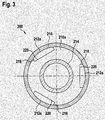
- the turbulence section 200 comprises a first inlet 206 through which water to be carbonized enters the turbulence section 200.
- the turbulence section 200 comprises a first outlet 208, through which carbonated water exits the turbulence section 200.
- the turbulence section 200 comprises a second inlet 202 through which water not to be carbonated enters, and a second outlet 204, through which water not to be carbonated exits from the turbulence section 200.
- a plurality of turbulence generation elements 210a, 210b, 210c, 210d are arranged.
- the plurality of turbulence generation elements 210a, 210b, 210c, 210d are formed integrally with a second pipe 214 formed between the second inlet 202 and the second outlet 204.
- a first pipe 216 is extending connecting the first inlet 206 with the first outlet 208.
- the turbulence generation elements 210 are generally solid and extend from the second pipe 214 to the first pipe 216. At the outer perimeter of the generally circular turbulence generation element 210 a plurality of turbulence generation openings 212a, 212b, 212c, 212d are arranged. The turbulence generation openings 212a may be arranged along the perimeter of the turbulence generation elements 210a. In the embodiment shown in figures 3 , three turbulence generation openings 212a are arranged along (around) the perimeter of the turbulence generation element 210a.
- more turbulence generation openings or less turbulence generation openings may be arranged along the perimeter of the turbulence generation element 210a, such as two turbulence generation openings, four turbulence generation openings or more turbulence generation openings.
- each turbulence generation opening may comprise a first portion 220 extending generally perpendicular to the radial direction of the turbulence generation element. Perpendicular to the first portion 220 of the turbulence generation opening a second portion 218 may be arranged.
- a plurality of turbulence generation elements 210a, 210b, 210c, 210d and/or a plurality of turbulence generation openings 212a, 212b, 212c, 212d may be arranged in serial relationship in the flow direction indicated by the arrows in figure 2 .
- the turbulence generation elements 210a, 210b, 210c, 210d may be spaced apart to form turbulence chambers 222a, 222b, 222c, 220d, 220e in front of the turbulence generation elements 210a, between the turbulence generation elements 210a, 210b, 210c, 210d and/or behind the turbulence generation element 210d in the flow direction of the water to be carbonized.
- the inventors of the present invention assume that carbon dioxide bubbles are split up at the turbulence generation openings 212a, 212b, 212c, 212d and solved in the water.
- turbulence generation openings 212a, 212b, 212c, 212d a higher pressure is generated, resulting in that the carbon dioxide bubbles are solved in the beverage and water, respectively.
- the turbulence generated in the turbulence chambers 222a, 222b, 222c, 222d, 222e results in that the beverage and water, respectively solves the carbon dioxide.
- the thickness of the turbulence generation elements 210a, 210b, 210c, 210d may range between approximately 1 mm to 3 mm.
- the distance between two turbulence generation elements 210a, 210b, 210c, 210d may range between 3 to 7 mm.
- the inner diameter of the first pipe 216 may range between 7 and 10 mm, and the outer diameter of the second pipe may range between 4 and 6 mm.
- first pipe 216 and the second pipe 214 are drawn to be concentric. This does not have to be the case, the first pipe 216 and the second pipe 214 may be coupled thermally by any suitable means, such as a heat conductor, for example copper, or a heat pipe.
- the turbulence section 200 is connected to a valve 222.
- the inlet 218 of the valve 222 is connected to the pipe 136 transporting beverage and water, respectively from the flow-type water tempering device 128.
- the valve 222 is operatively connected to the controller 150. If the controller 150 determines that water is not to be carbonized, the water entering the valve 222 at the inlet 218 is passed to a second outlet pipe 230 of the valve 222 and enters the second inlet 202 of the turbulence section 200.
- Water not to be carbonized may be water for preparing tea, coffee or still water.
- the water flowing in the second pipe 214 does not pass any turbulence elements and no carbon dioxide has been injected by the first and second injection valves 124, 126. Therefore, the water exits the second outlet 204 without being carbonized and enters the nozzle 140.
- the controller 150 determines that water is to be carbonized, carbon dioxide is injected by the first and/or second injection valve 124, 126. Further, the valve 222 is switched such that beverage and water, respectively entering the inlet 218 of the valve 222 is passed to a first outlet pipe 240 of the valve 222, wherein the first outlet pipe 240 is connected to the first inlet 206 of the turbulence device 200.
- the beverage and water respectively passes the turbulence generation elements 210a, 210b, 210c, 210d comprising the turbulence generation openings 212a, 212b, 212c, 212d, respectively, in which the carbon dioxide bubbles are split up and solved by the beverage and water respectively, as described above.
- the controller 150 may pass water heated by the flow-type water heater 107 and optionally supplemented by the cleaning agent dispensing device 109 to the second pipe 214 by switching the valve 222 such that the hot water is flowing from the inlet 218 of the valve 222 to the second outlet pipe 230.
- the hot water enters the second inlet and heats the second pipe 214 and the turbulence generation elements 210a, 210b, 210c, 210d and thus also the first pipe 216.
- the turbulence elements 200 is effectively disinfected and/or sterilized.
- the controller 150 may switch the valve 222 in a second step such that hot water flows from the inlet 218 of the valve 222 to the first pipe outlet 240 and thus into the first inlet 206 for removing the destroyed germs, pathogens and virus from the turbulence chambers 222a, 222b, 222c, 220d, 222e and the turbulence generation opening 212a, 212b, 212c, 212d.
- the first embodiment of the turbulence chamber 200 allows effective flow-type carbonization by a flow-type turbulence section 200 by turbulence chambers 222a, 222b, 222c, 220d, 220e and turbulence openings 212a, 212b, 212c, 212d.
- the turbulence generation openings restrict the flow of a liquid, the turbulence section can be effectively disinfected and/or sterilized, since hot sterilizing liquid may be passed between the second inlet 202 and the second outlet 204 and since the liquid flowing from the second inlet 202 to the second outlet 204 is in thermal communication with the turbulence generation elements 210a, 210b, 210c, 210d and the first pipe 216.
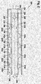
- FIG 4 showing a schematic cut away view of a turbulence section (flow-type carbonization device) 300 according to a third embodiment of the present invention.
- the turbulence section 300 comprises essentially four chambers 318a, 318b, 318c, 316d formed by outer pipe portions 308a-308h of a plurality of turbulence elements 306a-306h.
- an inner pipe portion 310a of a first turbulence element 306a extends. Between the outer pipe portion 308a and the inner pipe portion 310a a recess 314a is formed. Between the outer pipe portion 308a and the inner pipe portion 310a a dividing wall 316a is arranged. The outer pipe portion 308a and the dividing wall 316a may form a cylinder, wherein the inner pipe portion 310a extends through the dividing wall 316a. The inner pipe portion 310a forms a fluid passage, wherein the fluid enters through the orifice 312a of the inner pipe portion 310a into the first chamber 316a. The outer pipe section 308a of the first turbulence element 306a extends further in the downstream direction as the inner pipe portion 310a of the first turbulence element 306a. The flow direction is indicated in Fig. 4 by arrows.
- the second turbulence element 306b Adjacent to the first turbulence element 306a a second turbulence element 306b is located.
- the second turbulence element 306b is shaped essentially the same way as the first turbulence element 306a. Thus, for the sake of brevity, the second turbulence element is not described detail.
- the second turbulence element also comprises an outer pipe portion 308b connected by a dividing wall 316b with an inner pipe portion 310b.
- the second turbulence element 306b is arranged such in the turbulence section 300 that an orifice 312b of the inner pipe portion 316b of the second turbulence element 306b faces the orifice 312a of the inner pipe portion 310a of the first turbulence element 306a.
- the inner pipe portion 310b of the second turbulence element 306b extends upstream into the first chamber 318a.
- the fluid enters through an orifice 312b in the inner pipe portion 310b of the second turbulence element 306b.
- the outer pipe portion 308b extends further from the divisional wall 316b in the upstream direction as the inner pipe portion 310b.
- a recess 314b is formed between the outer pipe portion 308b of the second turbulence element 306b and the inner pipe portion 310b .
- first turbulence element 306a and second turbulence element 306b can form in one embodiment a turbulence section having a single chamber 318a.
- a plurality of a chambers 318a-318d and a plurality of turbulence elements 306a-306h can be arranged in serial flow communication.
- a third turbulence element 306c is arranged adjacent to the second turbulence element 306b adjacent to the second turbulence element 306b .
- the third turbulence element 306c is shaped essentially the same way as the first turbulence element 306a.
- a divisional wall 316c of the third turbulence element 306c is arranged adjacent (face-to-face) to the divisional wall 316b of the second turbulence element 306b.
- the inner pipe portion 310c of the third turbulence element extends downstream into the chamber 318b formed by the outer pipe portion 308c of the third turbulence element 306c.
- the fluid flows through the passage formed by the inner pipe portion 312b of the second turbulence element and the inner pipe portion 312c of the third turbulence element 306c and enters through the orifice 312c of the inner pipe portion 310c of the third turbulence element 306c into the chamber 318b. Between the outer pipe portion 308c and the inner pipe portion 310c a recess 314c is formed.
- the fourth turbulence element 306d Adjacent to the third turbulence element 306c a fourth turbulence element 306d is located.
- the fourth turbulence element 306d is shaped essentially the same way as the first turbulence element 306a. Thus, for the sake of brevity, the fourth turbulence element is not described detail.
- the fourth turbulence element also comprises an outer pipe portion 308d connected by a dividing wall 316d with an inner pipe portion 310d.
- the fourth turbulence element 306d is arranged such in the turbulence section 300 that an orifice 312d of the inner pipe portion 310d of the fourth turbulence element 306d faces the orifice 312c of the inner pipe portion 310c of the third turbulence element 306c.
- the inner pipe portion 310d of the fourth turbulence element 306d extends upstream into the second chamber 318b.
- the fluid enters through an orifice 312d from the chamber 318b in the of the inner pipe portion 310d of the second turbulence element 306d.
- the outer pipe portion 308d extends further from the divisional wall 316b in downstream direction as the inner pipe portion 310d. Between the outer pipe portion 308d of the fourth turbulence element 306d and the inner pipe portion 310d a recess 314d is formed.
- a fifth turbulence element 306e Adjacent to the fourth turbulence element 306d a fifth turbulence element 306e is arranged.
- the fifth turbulence element 306e is shaped essentially the same way as the first turbulence element 306a.
- a divisional wall 316e of the fifth turbulence element 306d is arranged adjacent (face-to-face) to the divisional wall 316d of the fourth turbulence element.
- the inner pipe portion 310e of the fifth turbulence element extends downstream into a third chamber 318c formed by the outer pipe portion 308e of the fifth turbulence element 306e.
- the fluid flows through the passage formed by the inner pipe portion 312d of the fourth turbulence element and the inner pipe portion 310e of the fifth turbulence element 306e and enters through the orifice 312e of the inner pipe portion 310e of the fifth turbulence element 306e into the chamber 318c. Between the outer pipe portion 308e and the inner pipe portion 310e a recess 314e is formed.
- a sixth turbulence element 306f Adjacent to the fifth turbulence element 306e a sixth turbulence element 306f is located.
- the sixth turbulence element 306f is shaped essentially the same way as the first turbulence element 306a.
- the sixth turbulence element also comprises an outer pipe portion 308f connected by a dividing wall 316f with an inner pipe portion 310f.
- the sixth turbulence element 306f is arranged such in the turbulence section 300 that an orifice 312f of the inner pipe portion 316f of the sixth turbulence element 306f faces the orifice 312e of the inner pipe portion 310e of the fifth turbulence element 306e.
- the inner pipe portion 310f of the sixth turbulence element 306f extends upstream into the third chamber 318c.
- a seventh turbulence element 306g Adjacent to the sixth turbulence element 306f a seventh turbulence element 306g is arranged.
- the seventh turbulence element 306g is shaped essentially the same way as the first turbulence element 306a.
- a divisional wall 316g of the seventh turbulence element 306g is arranged adjacent (face-to-face) to the divisional wall 316f of the sixth turbulence element.
- the inner pipe portion 310g of the seventh turbulence element extends downstream into a fourth chamber 318d formed by the outer pipe portion 308g of the seventh turbulence element 306g.
- the fluid flows through the passage formed by the inner pipe portion 312f of the sixth turbulence element 306f and the inner pipe portion 310g of the seventh turbulence element 306g and enters through the orifice 312g of the inner pipe portion 310g of the seventh turbulence element 306g into the fourth chamber 318d. Between the outer pipe portion 308g and the inner pipe portion 310g a recess 314g is formed.
- an eighth turbulence element 306h Adjacent to the seventh turbulence element 306g an eighth turbulence element 306h is located.
- the eighth turbulence element 306h is shaped essentially the same way as the first turbulence element 306a.
- the eighth turbulence element 306h also comprises an outer pipe portion 308h connected by a dividing wall 316h with an inner pipe portion 310h.
- the eighth turbulence element 306h is arranged such in the turbulence section 300 that an orifice 312h of the inner pipe portion 316h of the eighth turbulence element 306h faces the orifice 312g of the inner pipe portion 310g of the seventh turbulence element 306g.
- the inner pipe portion 310h of the eighth turbulence element 306h extends downstream into the fourth chamber 318d.
- the distance between the orifices 312a-312h of opposing inner pipe portions 310a-310h facing each other ranges approximately from 3.5 mm to approximately 12 mm, preferably from approximately 4.5 mm to approximately 10 mm, more preferred from approximately 6 mm to approximately 8 mm.
- the length of a flow channel formed by a first inner pipe portion 310a-310h extending in an upstream chamber 318a-318c and a second inner pipe portion 310a-310h extending in a downstream chamber 318b-318d adjacent to the first chamber ranges from approximately 3.5 mm to approximately 12 mm, preferably from approximately 4.5 mm to approximately 10 mm, more preferred from approximately 6 mm to approximately 8 mm.
- the diameter of the inner pipe portion 310a-310h may range from approximately 0.5 mm to approximately 3 mm, preferably from approximately 0.7 mm to approximately 2 mm, more preferred from approximately 1 mm to approximately 1.5 mm.
- the thickness of the wall of the inner pipe portion 310a-310h ranges from approximately 0.3 mm to approximately 1.5 mm, preferably from approximately 0.5 mm to approximately 1 mm, more preferred from approximately 0.7 mm to approximately 0.8 mm.
- the inner pipe portion 310a-310h may extend from the dividing wall 316a-316h approximately 1 mm to approximately 3 mm, preferably approximately 1.5 mm to 2.5 mm, more preferred approximately 1.7 mm to approximately 2.2 mm into the chamber.
- the inner diameter of the outer pipe portion 308a-308h ranges between approximately 4 mm to approximately 10 mm, preferably between approximately 4 mm to approximately 8 mm, most preferred between approximately 5 mm to approximately 7 mm.
- a fluid in this embodiment the fluid comprising water and carbon dioxide, enters through the orifices 312a, 312c, 312e, 312g of the first, third, fifth and seventh turbulence element 306a, 306c, 306e, 306g into the respective chamber 318a, 318b, 318c, 318d.
- the inventors assume without wishing to be bound to a specific theory that at the orifice 312a, 312c, 312e, 312g the carbon dioxide bubbles are split up and distributed in the water and dissolve in the water.
- the recess 314a, 314c, 314e, 314g around the inner pipe portion 310a, 310c, 310e, 310g forms a turbulent flow of the fluid in which the water can dissolve carbon dioxide in a particular efficient way.
- the recess 314a, 314c, 314e, 314g cause a particular turbulence flow in the chambers 318a, 318b, 318c, 318d contributing to solving carbon dioxide in water.
- the recess 314b, 314d, 314f, 314h between the outer pipe portion 306b, 306d, 306f, 306h and the inner pipe portion 316b, 316d, 316f, 316h increase the turbulence of the flow in the chamber 318a, 318b, 318c, 318d adding to the efficiency of the carbonization.
- the flow of water through the turbulence section 300 is less than 1 I per minute, preferably between 0.5 I per minute to 1 I per minute. If the water to carbonite has a temperature of 2°C a carbon dioxide concentration of 5 g/l can be achieved with the present carbonization device. If the water has a temperature of 8°C a carbon dioxide concentration of 4 g/l may be achieved with the inventive flow-type carbonization device. This corresponds to an efficiency of approximately 60%.
- the water fed through the gas inlet portion 110 and/or the turbulence section 300 may have a pressure from approximately 3 bar to approximately 4 bar.
Priority Applications (8)
| Application Number | Priority Date | Filing Date | Title |
|---|---|---|---|
| AU2019204851A AU2019204851A1 (en) | 2018-07-11 | 2019-07-05 | Flow-type carbonization device with improved disinfection properties and beverage dispenser having such device |
| RU2019120987A RU2019120987A (ru) | 2018-07-11 | 2019-07-05 | Проточное устройство газирования с улучшенными дезинфицирующими свойствами и аппарат для розлива напитков, содрежащий такое устройство |
| CA3049374A CA3049374A1 (fr) | 2018-07-11 | 2019-07-09 | Appareil de carbonisation a jet ayant des proprietes desinfectantes ameliorees et un distributeur de breuvages dote d`un tel appareil |
| CN201910624104.2A CN110754945B (zh) | 2018-07-11 | 2019-07-11 | 流动类型碳化装置以及设有此装置的饮料分配器 |
| BR102019014428A BR102019014428A2 (pt) | 2018-07-11 | 2019-07-11 | dispositivo de carbonatação do tipo fluxo com propriedades de desinfecção melhoradas e dispensador de bebidas com tal dispositivo |
| US16/508,622 US20200017349A1 (en) | 2018-07-11 | 2019-07-11 | Flow-type carbonization device with improved disinfection properties and beverage dispenser having such device |
| MX2019008362A MX2019008362A (es) | 2018-07-11 | 2019-07-11 | Dispositivo dispensador de carbonizacion con propiedades de desinfeccion mejoradas y dispensador de bebidas que contiene dicho dispositivo. |
| KR1020190083713A KR20200006942A (ko) | 2018-07-11 | 2019-07-11 | 개선된 소독 특성을 갖는 유동형 탄산화 장치와 이러한 장치가 있는 음료 디스펜서 |
Applications Claiming Priority (1)
| Application Number | Priority Date | Filing Date | Title |
|---|---|---|---|
| EP18182943.3A EP3594173A1 (fr) | 2018-07-11 | 2018-07-11 | Saturateur en ligne avec chambre de turbulence modulaire; distributeur de boissons avec ledit saturateur |
Publications (2)
| Publication Number | Publication Date |
|---|---|
| EP3594174A1 true EP3594174A1 (fr) | 2020-01-15 |
| EP3594174B1 EP3594174B1 (fr) | 2021-03-31 |
Family
ID=62916552
Family Applications (2)
| Application Number | Title | Priority Date | Filing Date |
|---|---|---|---|
| EP18182943.3A Pending EP3594173A1 (fr) | 2018-07-11 | 2018-07-11 | Saturateur en ligne avec chambre de turbulence modulaire; distributeur de boissons avec ledit saturateur |
| EP19184191.5A Active EP3594174B1 (fr) | 2018-07-11 | 2019-07-03 | Dispositif de carbonisation de type flux présentant des propriétés de désinfection et distributeur de boissons doté d'un tel dispositif |
Family Applications Before (1)
| Application Number | Title | Priority Date | Filing Date |
|---|---|---|---|
| EP18182943.3A Pending EP3594173A1 (fr) | 2018-07-11 | 2018-07-11 | Saturateur en ligne avec chambre de turbulence modulaire; distributeur de boissons avec ledit saturateur |
Country Status (9)
| Country | Link |
|---|---|
| US (1) | US20200017349A1 (fr) |
| EP (2) | EP3594173A1 (fr) |
| KR (1) | KR20200006942A (fr) |
| CN (1) | CN110754945B (fr) |
| AU (1) | AU2019204851A1 (fr) |
| BR (1) | BR102019014428A2 (fr) |
| CA (1) | CA3049374A1 (fr) |
| MX (1) | MX2019008362A (fr) |
| RU (1) | RU2019120987A (fr) |
Families Citing this family (1)
| Publication number | Priority date | Publication date | Assignee | Title |
|---|---|---|---|---|
| WO2020206535A1 (fr) * | 2019-04-09 | 2020-10-15 | 2689287 Ontario Inc. | Distributeur de boissons, kit de montage du distributeur et procédés correspondants de fabrication, de montage et de fonctionnement associés |
Citations (5)
| Publication number | Priority date | Publication date | Assignee | Title |
|---|---|---|---|---|
| US3339805A (en) * | 1966-09-21 | 1967-09-05 | Clarence W Wheeler | Carbonated water carbonator and dispenser |
| US3761066A (en) * | 1971-09-08 | 1973-09-25 | C Wheeler | Inline water carbonator |
| EP0322925A2 (fr) | 1987-12-30 | 1989-07-05 | Praxair Technology, Inc. | Procédé pour disperser du gaz |
| WO2012123462A1 (fr) | 2011-03-14 | 2012-09-20 | Biologic Gmbh | Procédé de production en portions de boissons aqueuses carbonatées à mélanger pour la consommation directe, capsule à boisson et appareil ménager de carbonatation et d'aromatisation d'eau en portions |
| US20160216045A1 (en) * | 2013-09-30 | 2016-07-28 | Hong Kong Modern Technology Limited | Fluid heat exchanger and energy recycling device |
Family Cites Families (13)
| Publication number | Priority date | Publication date | Assignee | Title |
|---|---|---|---|---|
| US3565405A (en) * | 1968-11-07 | 1971-02-23 | Vendo Co | Turbulent flow carbonator |
| US3636607A (en) * | 1969-12-30 | 1972-01-25 | United Aircraft Prod | Method of making a heat exchange tube |
| US4304736A (en) * | 1980-01-29 | 1981-12-08 | The Coca-Cola Company | Method of and apparatus for making and dispensing a carbonated beverage utilizing propellant carbon dioxide gas for carbonating |
| DE3017574C2 (de) * | 1980-05-08 | 1985-06-05 | Wieland-Werke Ag, 7900 Ulm | Abstandshalter für koaxiale Wärmeübertrager |
| JPS60166089A (ja) * | 1984-02-08 | 1985-08-29 | Matsushita Electric Ind Co Ltd | ミネラル水製造装置 |
| US5021250A (en) * | 1989-01-10 | 1991-06-04 | Filtercold Corporation | Apparatus and method for dispensing purified and carbonated liquids |
| US5062474A (en) * | 1990-01-26 | 1991-11-05 | General Motors Corporation | Oil cooler |
| US5510060A (en) * | 1995-03-14 | 1996-04-23 | Knoll; George W. | Inline carbonator |
| US6889603B2 (en) * | 2002-12-24 | 2005-05-10 | Nestec S.A. | Clean-in-place automated food or beverage dispenser |
| US7861544B2 (en) * | 2008-11-17 | 2011-01-04 | EcoloBlue, Inc. | Apparatus and methods for creating sparkling water from the atmosphere |
| CH706586B1 (de) * | 2012-06-04 | 2016-04-15 | Schaerer Ag | Ausgabeeinheit für einen Getränkeautomaten, Getränkeautomat mit einer solchen Ausgabeeinheit sowie Verfahren zum Betrieb eines solchen Getränkeautomaten. |
| US20180127254A1 (en) * | 2016-11-09 | 2018-05-10 | Bsh Hausgeraete Gmbh | Drink producing apparatus with closed carbon dioxide line circuit, household refrigeration apparatus and method for operating a drink producing apparatus |
| NL2017940B1 (en) * | 2016-12-06 | 2018-06-19 | Apiqe Holdings Llc | Water dispensers for dispensing carbonized water |
-
2018
- 2018-07-11 EP EP18182943.3A patent/EP3594173A1/fr active Pending
-
2019
- 2019-07-03 EP EP19184191.5A patent/EP3594174B1/fr active Active
- 2019-07-05 AU AU2019204851A patent/AU2019204851A1/en not_active Abandoned
- 2019-07-05 RU RU2019120987A patent/RU2019120987A/ru unknown
- 2019-07-09 CA CA3049374A patent/CA3049374A1/fr not_active Abandoned
- 2019-07-11 BR BR102019014428A patent/BR102019014428A2/pt not_active Application Discontinuation
- 2019-07-11 MX MX2019008362A patent/MX2019008362A/es unknown
- 2019-07-11 KR KR1020190083713A patent/KR20200006942A/ko unknown
- 2019-07-11 CN CN201910624104.2A patent/CN110754945B/zh active Active
- 2019-07-11 US US16/508,622 patent/US20200017349A1/en not_active Abandoned
Patent Citations (5)
| Publication number | Priority date | Publication date | Assignee | Title |
|---|---|---|---|---|
| US3339805A (en) * | 1966-09-21 | 1967-09-05 | Clarence W Wheeler | Carbonated water carbonator and dispenser |
| US3761066A (en) * | 1971-09-08 | 1973-09-25 | C Wheeler | Inline water carbonator |
| EP0322925A2 (fr) | 1987-12-30 | 1989-07-05 | Praxair Technology, Inc. | Procédé pour disperser du gaz |
| WO2012123462A1 (fr) | 2011-03-14 | 2012-09-20 | Biologic Gmbh | Procédé de production en portions de boissons aqueuses carbonatées à mélanger pour la consommation directe, capsule à boisson et appareil ménager de carbonatation et d'aromatisation d'eau en portions |
| US20160216045A1 (en) * | 2013-09-30 | 2016-07-28 | Hong Kong Modern Technology Limited | Fluid heat exchanger and energy recycling device |
Also Published As
| Publication number | Publication date |
|---|---|
| EP3594174B1 (fr) | 2021-03-31 |
| AU2019204851A1 (en) | 2020-01-30 |
| CN110754945A (zh) | 2020-02-07 |
| KR20200006942A (ko) | 2020-01-21 |
| EP3594173A1 (fr) | 2020-01-15 |
| CN110754945B (zh) | 2023-01-17 |
| RU2019120987A (ru) | 2021-01-12 |
| MX2019008362A (es) | 2020-07-13 |
| US20200017349A1 (en) | 2020-01-16 |
| BR102019014428A2 (pt) | 2020-01-28 |
| CA3049374A1 (fr) | 2020-01-11 |
Similar Documents
| Publication | Publication Date | Title |
|---|---|---|
| EP3107645B1 (fr) | Carbonatation en ligne de boissons à base d'eau | |
| BR0308624A (pt) | Aparelho e método para o preparo e distribuição de combustìvel | |
| EP3594174B1 (fr) | Dispositif de carbonisation de type flux présentant des propriétés de désinfection et distributeur de boissons doté d'un tel dispositif | |
| EP1785151A1 (fr) | Désinfection thermique pour systèmes d'osmose inverse | |
| CN103188941A (zh) | 使用液体的热喷雾装置以及相关的方法 | |
| CN203147722U (zh) | 蒸汽加热器和壶 | |
| WO2008083789A3 (fr) | Distributeur d'eau et dispositif de distribution de boissons équipé d'un distributeur d'eau | |
| JP5118644B2 (ja) | 液体材料気化装置 | |
| CN110312452A (zh) | 用于加热奶或奶泡的装置 | |
| US7779864B2 (en) | Infusion/mass transfer of treatment substances into substantial liquid flows | |
| WO2002001970A3 (fr) | Appareil de chauffage a injection de vapeur et procede | |
| RU2010100808A (ru) | Емкость, содержащая слой гранул, и система распределения газовой и жидкой фаз, циркулирующих в упомянутой емкости в восходящем потоке | |
| JP2021014270A (ja) | 改善された消毒特性を有するフロー型炭酸化装置およびそのような装置を有する飲料ディスペンサ | |
| US5442921A (en) | Targeted fluid delivery system | |
| NO20092245L (no) | Fremgangsmate og anordning for injisering av oksygen i en reaksjonsgass som strommer gjennom en syntesereaktor | |
| JP4546452B2 (ja) | スチーム・インゼクタの改良 | |
| RU2195586C2 (ru) | Многосопловый струйный аппарат | |
| ZA200206229B (en) | Steam heater. | |
| KR20160040923A (ko) | 탄산수 생성장치 | |
| JP4511414B2 (ja) | 気化器 | |
| KR20180130070A (ko) | 나노 기포 발생기 | |
| JP2007078277A (ja) | 蒸気加熱装置 | |
| WO2024035701A1 (fr) | Moteur à vapeur et système d'introduction de vapeur | |
| RU2361166C1 (ru) | Струйный водопаровой теплообменник | |
| US20220010957A1 (en) | Cylindrical burner apparatus and method |
Legal Events
| Date | Code | Title | Description |
|---|---|---|---|
| PUAI | Public reference made under article 153(3) epc to a published international application that has entered the european phase |
Free format text: ORIGINAL CODE: 0009012 |
|
| STAA | Information on the status of an ep patent application or granted ep patent |
Free format text: STATUS: THE APPLICATION HAS BEEN PUBLISHED |
|
| AK | Designated contracting states |
Kind code of ref document: A1 Designated state(s): AL AT BE BG CH CY CZ DE DK EE ES FI FR GB GR HR HU IE IS IT LI LT LU LV MC MK MT NL NO PL PT RO RS SE SI SK SM TR |
|
| AX | Request for extension of the european patent |
Extension state: BA ME |
|
| STAA | Information on the status of an ep patent application or granted ep patent |
Free format text: STATUS: REQUEST FOR EXAMINATION WAS MADE |
|
| 17P | Request for examination filed |
Effective date: 20200714 |
|
| RBV | Designated contracting states (corrected) |
Designated state(s): AL AT BE BG CH CY CZ DE DK EE ES FI FR GB GR HR HU IE IS IT LI LT LU LV MC MK MT NL NO PL PT RO RS SE SI SK SM TR |
|
| GRAJ | Information related to disapproval of communication of intention to grant by the applicant or resumption of examination proceedings by the epo deleted |
Free format text: ORIGINAL CODE: EPIDOSDIGR1 |
|
| GRAP | Despatch of communication of intention to grant a patent |
Free format text: ORIGINAL CODE: EPIDOSNIGR1 |
|
| GRAP | Despatch of communication of intention to grant a patent |
Free format text: ORIGINAL CODE: EPIDOSNIGR1 |
|
| STAA | Information on the status of an ep patent application or granted ep patent |
Free format text: STATUS: GRANT OF PATENT IS INTENDED |
|
| INTG | Intention to grant announced |
Effective date: 20201027 |
|
| GRAS | Grant fee paid |
Free format text: ORIGINAL CODE: EPIDOSNIGR3 |
|
| GRAA | (expected) grant |
Free format text: ORIGINAL CODE: 0009210 |
|
| STAA | Information on the status of an ep patent application or granted ep patent |
Free format text: STATUS: THE PATENT HAS BEEN GRANTED |
|
| AK | Designated contracting states |
Kind code of ref document: B1 Designated state(s): AL AT BE BG CH CY CZ DE DK EE ES FI FR GB GR HR HU IE IS IT LI LT LU LV MC MK MT NL NO PL PT RO RS SE SI SK SM TR |
|
| REG | Reference to a national code |
Ref country code: GB Ref legal event code: FG4D Ref country code: CH Ref legal event code: EP |
|
| REG | Reference to a national code |
Ref country code: AT Ref legal event code: REF Ref document number: 1376742 Country of ref document: AT Kind code of ref document: T Effective date: 20210415 |
|
| REG | Reference to a national code |
Ref country code: DE Ref legal event code: R096 Ref document number: 602019003564 Country of ref document: DE |
|
| REG | Reference to a national code |
Ref country code: IE Ref legal event code: FG4D |
|
| REG | Reference to a national code |
Ref country code: LT Ref legal event code: MG9D |
|
| PG25 | Lapsed in a contracting state [announced via postgrant information from national office to epo] |
Ref country code: NO Free format text: LAPSE BECAUSE OF FAILURE TO SUBMIT A TRANSLATION OF THE DESCRIPTION OR TO PAY THE FEE WITHIN THE PRESCRIBED TIME-LIMIT Effective date: 20210630 Ref country code: HR Free format text: LAPSE BECAUSE OF FAILURE TO SUBMIT A TRANSLATION OF THE DESCRIPTION OR TO PAY THE FEE WITHIN THE PRESCRIBED TIME-LIMIT Effective date: 20210331 Ref country code: BG Free format text: LAPSE BECAUSE OF FAILURE TO SUBMIT A TRANSLATION OF THE DESCRIPTION OR TO PAY THE FEE WITHIN THE PRESCRIBED TIME-LIMIT Effective date: 20210630 Ref country code: FI Free format text: LAPSE BECAUSE OF FAILURE TO SUBMIT A TRANSLATION OF THE DESCRIPTION OR TO PAY THE FEE WITHIN THE PRESCRIBED TIME-LIMIT Effective date: 20210331 |
|
| PG25 | Lapsed in a contracting state [announced via postgrant information from national office to epo] |
Ref country code: RS Free format text: LAPSE BECAUSE OF FAILURE TO SUBMIT A TRANSLATION OF THE DESCRIPTION OR TO PAY THE FEE WITHIN THE PRESCRIBED TIME-LIMIT Effective date: 20210331 Ref country code: SE Free format text: LAPSE BECAUSE OF FAILURE TO SUBMIT A TRANSLATION OF THE DESCRIPTION OR TO PAY THE FEE WITHIN THE PRESCRIBED TIME-LIMIT Effective date: 20210331 Ref country code: LV Free format text: LAPSE BECAUSE OF FAILURE TO SUBMIT A TRANSLATION OF THE DESCRIPTION OR TO PAY THE FEE WITHIN THE PRESCRIBED TIME-LIMIT Effective date: 20210331 |
|
| REG | Reference to a national code |
Ref country code: NL Ref legal event code: MP Effective date: 20210331 |
|
| REG | Reference to a national code |
Ref country code: AT Ref legal event code: MK05 Ref document number: 1376742 Country of ref document: AT Kind code of ref document: T Effective date: 20210331 |
|
| PG25 | Lapsed in a contracting state [announced via postgrant information from national office to epo] |
Ref country code: CZ Free format text: LAPSE BECAUSE OF FAILURE TO SUBMIT A TRANSLATION OF THE DESCRIPTION OR TO PAY THE FEE WITHIN THE PRESCRIBED TIME-LIMIT Effective date: 20210331 Ref country code: EE Free format text: LAPSE BECAUSE OF FAILURE TO SUBMIT A TRANSLATION OF THE DESCRIPTION OR TO PAY THE FEE WITHIN THE PRESCRIBED TIME-LIMIT Effective date: 20210331 Ref country code: LT Free format text: LAPSE BECAUSE OF FAILURE TO SUBMIT A TRANSLATION OF THE DESCRIPTION OR TO PAY THE FEE WITHIN THE PRESCRIBED TIME-LIMIT Effective date: 20210331 Ref country code: NL Free format text: LAPSE BECAUSE OF FAILURE TO SUBMIT A TRANSLATION OF THE DESCRIPTION OR TO PAY THE FEE WITHIN THE PRESCRIBED TIME-LIMIT Effective date: 20210331 Ref country code: SM Free format text: LAPSE BECAUSE OF FAILURE TO SUBMIT A TRANSLATION OF THE DESCRIPTION OR TO PAY THE FEE WITHIN THE PRESCRIBED TIME-LIMIT Effective date: 20210331 Ref country code: AT Free format text: LAPSE BECAUSE OF FAILURE TO SUBMIT A TRANSLATION OF THE DESCRIPTION OR TO PAY THE FEE WITHIN THE PRESCRIBED TIME-LIMIT Effective date: 20210331 |
|
| PG25 | Lapsed in a contracting state [announced via postgrant information from national office to epo] |
Ref country code: SK Free format text: LAPSE BECAUSE OF FAILURE TO SUBMIT A TRANSLATION OF THE DESCRIPTION OR TO PAY THE FEE WITHIN THE PRESCRIBED TIME-LIMIT Effective date: 20210331 Ref country code: PT Free format text: LAPSE BECAUSE OF FAILURE TO SUBMIT A TRANSLATION OF THE DESCRIPTION OR TO PAY THE FEE WITHIN THE PRESCRIBED TIME-LIMIT Effective date: 20210802 Ref country code: RO Free format text: LAPSE BECAUSE OF FAILURE TO SUBMIT A TRANSLATION OF THE DESCRIPTION OR TO PAY THE FEE WITHIN THE PRESCRIBED TIME-LIMIT Effective date: 20210331 Ref country code: PL Free format text: LAPSE BECAUSE OF FAILURE TO SUBMIT A TRANSLATION OF THE DESCRIPTION OR TO PAY THE FEE WITHIN THE PRESCRIBED TIME-LIMIT Effective date: 20210331 Ref country code: IS Free format text: LAPSE BECAUSE OF FAILURE TO SUBMIT A TRANSLATION OF THE DESCRIPTION OR TO PAY THE FEE WITHIN THE PRESCRIBED TIME-LIMIT Effective date: 20210731 |
|
| REG | Reference to a national code |
Ref country code: DE Ref legal event code: R097 Ref document number: 602019003564 Country of ref document: DE |
|
| PG25 | Lapsed in a contracting state [announced via postgrant information from national office to epo] |
Ref country code: DK Free format text: LAPSE BECAUSE OF FAILURE TO SUBMIT A TRANSLATION OF THE DESCRIPTION OR TO PAY THE FEE WITHIN THE PRESCRIBED TIME-LIMIT Effective date: 20210331 Ref country code: AL Free format text: LAPSE BECAUSE OF FAILURE TO SUBMIT A TRANSLATION OF THE DESCRIPTION OR TO PAY THE FEE WITHIN THE PRESCRIBED TIME-LIMIT Effective date: 20210331 Ref country code: ES Free format text: LAPSE BECAUSE OF FAILURE TO SUBMIT A TRANSLATION OF THE DESCRIPTION OR TO PAY THE FEE WITHIN THE PRESCRIBED TIME-LIMIT Effective date: 20210331 |
|
| PLBE | No opposition filed within time limit |
Free format text: ORIGINAL CODE: 0009261 |
|
| STAA | Information on the status of an ep patent application or granted ep patent |
Free format text: STATUS: NO OPPOSITION FILED WITHIN TIME LIMIT |
|
| 26N | No opposition filed |
Effective date: 20220104 |
|
| PG25 | Lapsed in a contracting state [announced via postgrant information from national office to epo] |
Ref country code: MC Free format text: LAPSE BECAUSE OF FAILURE TO SUBMIT A TRANSLATION OF THE DESCRIPTION OR TO PAY THE FEE WITHIN THE PRESCRIBED TIME-LIMIT Effective date: 20210331 |
|
| REG | Reference to a national code |
Ref country code: BE Ref legal event code: MM Effective date: 20210731 |
|
| PG25 | Lapsed in a contracting state [announced via postgrant information from national office to epo] |
Ref country code: IS Free format text: LAPSE BECAUSE OF FAILURE TO SUBMIT A TRANSLATION OF THE DESCRIPTION OR TO PAY THE FEE WITHIN THE PRESCRIBED TIME-LIMIT Effective date: 20210731 Ref country code: LU Free format text: LAPSE BECAUSE OF NON-PAYMENT OF DUE FEES Effective date: 20210703 |
|
| PG25 | Lapsed in a contracting state [announced via postgrant information from national office to epo] |
Ref country code: IE Free format text: LAPSE BECAUSE OF NON-PAYMENT OF DUE FEES Effective date: 20210703 Ref country code: BE Free format text: LAPSE BECAUSE OF NON-PAYMENT OF DUE FEES Effective date: 20210731 |
|
| PGFP | Annual fee paid to national office [announced via postgrant information from national office to epo] |
Ref country code: IT Payment date: 20220801 Year of fee payment: 4 Ref country code: DE Payment date: 20220801 Year of fee payment: 4 |
|
| PGFP | Annual fee paid to national office [announced via postgrant information from national office to epo] |
Ref country code: FR Payment date: 20220730 Year of fee payment: 4 |
|
| REG | Reference to a national code |
Ref country code: CH Ref legal event code: PL |
|
| PG25 | Lapsed in a contracting state [announced via postgrant information from national office to epo] |
Ref country code: LI Free format text: LAPSE BECAUSE OF NON-PAYMENT OF DUE FEES Effective date: 20220731 Ref country code: CH Free format text: LAPSE BECAUSE OF NON-PAYMENT OF DUE FEES Effective date: 20220731 |
|
| PG25 | Lapsed in a contracting state [announced via postgrant information from national office to epo] |
Ref country code: CY Free format text: LAPSE BECAUSE OF FAILURE TO SUBMIT A TRANSLATION OF THE DESCRIPTION OR TO PAY THE FEE WITHIN THE PRESCRIBED TIME-LIMIT Effective date: 20210331 |
|
| PG25 | Lapsed in a contracting state [announced via postgrant information from national office to epo] |
Ref country code: HU Free format text: LAPSE BECAUSE OF FAILURE TO SUBMIT A TRANSLATION OF THE DESCRIPTION OR TO PAY THE FEE WITHIN THE PRESCRIBED TIME-LIMIT; INVALID AB INITIO Effective date: 20190703 Ref country code: GR Free format text: LAPSE BECAUSE OF FAILURE TO SUBMIT A TRANSLATION OF THE DESCRIPTION OR TO PAY THE FEE WITHIN THE PRESCRIBED TIME-LIMIT Effective date: 20210331 |
|
| REG | Reference to a national code |
Ref country code: DE Ref legal event code: R119 Ref document number: 602019003564 Country of ref document: DE |
|
| GBPC | Gb: european patent ceased through non-payment of renewal fee |
Effective date: 20230703 |
|
| PG25 | Lapsed in a contracting state [announced via postgrant information from national office to epo] |
Ref country code: MK Free format text: LAPSE BECAUSE OF FAILURE TO SUBMIT A TRANSLATION OF THE DESCRIPTION OR TO PAY THE FEE WITHIN THE PRESCRIBED TIME-LIMIT Effective date: 20210331 Ref country code: DE Free format text: LAPSE BECAUSE OF NON-PAYMENT OF DUE FEES Effective date: 20240201 Ref country code: GB Free format text: LAPSE BECAUSE OF NON-PAYMENT OF DUE FEES Effective date: 20230703 |