EP0322925A2 - Procédé pour disperser du gaz - Google Patents
Procédé pour disperser du gaz Download PDFInfo
- Publication number
- EP0322925A2 EP0322925A2 EP88121913A EP88121913A EP0322925A2 EP 0322925 A2 EP0322925 A2 EP 0322925A2 EP 88121913 A EP88121913 A EP 88121913A EP 88121913 A EP88121913 A EP 88121913A EP 0322925 A2 EP0322925 A2 EP 0322925A2
- Authority
- EP
- European Patent Office
- Prior art keywords
- gas
- liquid
- flow
- venturi
- velocity
- Prior art date
- Legal status (The legal status is an assumption and is not a legal conclusion. Google has not performed a legal analysis and makes no representation as to the accuracy of the status listed.)
- Granted
Links
Images

Classifications
-
- B—PERFORMING OPERATIONS; TRANSPORTING
- B01—PHYSICAL OR CHEMICAL PROCESSES OR APPARATUS IN GENERAL
- B01F—MIXING, e.g. DISSOLVING, EMULSIFYING OR DISPERSING
- B01F23/00—Mixing according to the phases to be mixed, e.g. dispersing or emulsifying
- B01F23/20—Mixing gases with liquids
-
- B—PERFORMING OPERATIONS; TRANSPORTING
- B01—PHYSICAL OR CHEMICAL PROCESSES OR APPARATUS IN GENERAL
- B01J—CHEMICAL OR PHYSICAL PROCESSES, e.g. CATALYSIS OR COLLOID CHEMISTRY; THEIR RELEVANT APPARATUS
- B01J10/00—Chemical processes in general for reacting liquid with gaseous media other than in the presence of solid particles, or apparatus specially adapted therefor
- B01J10/002—Chemical processes in general for reacting liquid with gaseous media other than in the presence of solid particles, or apparatus specially adapted therefor carried out in foam, aerosol or bubbles
-
- B—PERFORMING OPERATIONS; TRANSPORTING
- B01—PHYSICAL OR CHEMICAL PROCESSES OR APPARATUS IN GENERAL
- B01F—MIXING, e.g. DISSOLVING, EMULSIFYING OR DISPERSING
- B01F25/00—Flow mixers; Mixers for falling materials, e.g. solid particles
- B01F25/30—Injector mixers
- B01F25/31—Injector mixers in conduits or tubes through which the main component flows
- B01F25/312—Injector mixers in conduits or tubes through which the main component flows with Venturi elements; Details thereof
- B01F25/3122—Injector mixers in conduits or tubes through which the main component flows with Venturi elements; Details thereof the material flowing at a supersonic velocity thereby creating shock waves
-
- B—PERFORMING OPERATIONS; TRANSPORTING
- B01—PHYSICAL OR CHEMICAL PROCESSES OR APPARATUS IN GENERAL
- B01J—CHEMICAL OR PHYSICAL PROCESSES, e.g. CATALYSIS OR COLLOID CHEMISTRY; THEIR RELEVANT APPARATUS
- B01J19/00—Chemical, physical or physico-chemical processes in general; Their relevant apparatus
- B01J19/26—Nozzle-type reactors, i.e. the distribution of the initial reactants within the reactor is effected by their introduction or injection through nozzles
-
- B—PERFORMING OPERATIONS; TRANSPORTING
- B01—PHYSICAL OR CHEMICAL PROCESSES OR APPARATUS IN GENERAL
- B01J—CHEMICAL OR PHYSICAL PROCESSES, e.g. CATALYSIS OR COLLOID CHEMISTRY; THEIR RELEVANT APPARATUS
- B01J2219/00—Chemical, physical or physico-chemical processes in general; Their relevant apparatus
- B01J2219/00049—Controlling or regulating processes
- B01J2219/00162—Controlling or regulating processes controlling the pressure
-
- B—PERFORMING OPERATIONS; TRANSPORTING
- B01—PHYSICAL OR CHEMICAL PROCESSES OR APPARATUS IN GENERAL
- B01J—CHEMICAL OR PHYSICAL PROCESSES, e.g. CATALYSIS OR COLLOID CHEMISTRY; THEIR RELEVANT APPARATUS
- B01J2219/00—Chemical, physical or physico-chemical processes in general; Their relevant apparatus
- B01J2219/00049—Controlling or regulating processes
- B01J2219/00164—Controlling or regulating processes controlling the flow
-
- Y—GENERAL TAGGING OF NEW TECHNOLOGICAL DEVELOPMENTS; GENERAL TAGGING OF CROSS-SECTIONAL TECHNOLOGIES SPANNING OVER SEVERAL SECTIONS OF THE IPC; TECHNICAL SUBJECTS COVERED BY FORMER USPC CROSS-REFERENCE ART COLLECTIONS [XRACs] AND DIGESTS
- Y10—TECHNICAL SUBJECTS COVERED BY FORMER USPC
- Y10S—TECHNICAL SUBJECTS COVERED BY FORMER USPC CROSS-REFERENCE ART COLLECTIONS [XRACs] AND DIGESTS
- Y10S261/00—Gas and liquid contact apparatus
- Y10S261/75—Flowing liquid aspirates gas
-
- Y—GENERAL TAGGING OF NEW TECHNOLOGICAL DEVELOPMENTS; GENERAL TAGGING OF CROSS-SECTIONAL TECHNOLOGIES SPANNING OVER SEVERAL SECTIONS OF THE IPC; TECHNICAL SUBJECTS COVERED BY FORMER USPC CROSS-REFERENCE ART COLLECTIONS [XRACs] AND DIGESTS
- Y10—TECHNICAL SUBJECTS COVERED BY FORMER USPC
- Y10S—TECHNICAL SUBJECTS COVERED BY FORMER USPC CROSS-REFERENCE ART COLLECTIONS [XRACs] AND DIGESTS
- Y10S261/00—Gas and liquid contact apparatus
- Y10S261/78—Sonic flow
Definitions
- This invention relates to the mixing of gases and liquids. More particularly, it relates to enhancing the dispersion of gases in liquids.
- gases are dispersed in liquids for numerous gas dissolution, gas-liquid reaction and gas stripping of dissolved gas applications.
- the interfacial surface area between the gas and liquid is appreciably increased as compared to said surface area between the liquid and a like quantity of gas in the form of larger gas bubbles.
- an increase in the interfacial surface area between the gas and liquid is known to increase the mass transfer of the gas from the gas bubbles into the liquid, as well as the transfer of dissolved gas from the liquid into the gas bubble.
- Garrett indicates that a flow velocity of at least about 2 meters per second should be used to establish a turbulent flow condition such as to create and maintain a uniform dispersion of gas bubbles in the liquid, apart from the oxygen that is dissolved in the waste water stream, immediately downstream of the point at which the side pipe for oxygen introduction joins the conduit through which the pressurized stream of waste water is being passed.
- a turbulent flow condition such as to create and maintain a uniform dispersion of gas bubbles in the liquid, apart from the oxygen that is dissolved in the waste water stream, immediately downstream of the point at which the side pipe for oxygen introduction joins the conduit through which the pressurized stream of waste water is being passed.
- a turbulent flow condition such as to create and maintain a uniform dispersion of gas bubbles in the liquid, apart from the oxygen that is dissolved in the waste water stream, immediately downstream of the point at which the side pipe for oxygen introduction joins the conduit through which the pressurized stream of waste water is being passed.
- such uniform dispersion of gas in liquid can be developed in a turbulent flow condition
- Garrett discloses the passage of the uniformly dispersed gas-liquid mixture formed at said velocity in the sub-sonic, but turbulent flow, range to a venturi for the acceleration of the flow velocity to a velocity in excess of the speed of sound in said gas-liquid mixture.
- Garrett states that, in the region of the venturi between its upstream end and its throat portion of minimum diameter, the velocity of said uniformly dispersed gas-liquid mixture increases and reaches a velocity in excess of the velocity of sound in said dispersion, and that a sonic shock wave is created within said region of the venturi.
- the relatively coarse bubbles of oxygen in the dispersion are sheared into smaller or finer bubbles by the turbulence resulting from the shock wave.
- the pressurized stream After passing through the throat of the venturi, the pressurized stream is deaccelerated as the venturi widens until it is returned to a sub-sonic velocity, which is nevertheless sufficiently high to maintain turbulent flow and the uniform dispersion of oxygen bubbles in the waste water stream.
- Garrett also discloses that, in the event the oxygen were introduced into the waste water stream through the throat of the venturi, as is conventionally accomplished for certain gas-liquid mixing operations, no sonic shock wave would be produced in the upstream, converging portion of the venturi.
- venturi devices to enhance the dispersion of a gas in a liquid
- Such requirements pertain to gas-liquid processing operations in general, and are related to the continual desire in the art for improvement in industrial processing operations.
- Enhanced gas dispersion is achieved by introducing the gas into the liquid in close proximity to flow constriction means used to create supersonic flow velocities.
- Flow velocities upstream of the constriction need not be great enough to create and maintain turbulent flow conditions.
- the gas and liquid need not be uniformly dispersed prior to the acceleration of the gas-liquid mixture to supersonic velocity, and its subsequent deacceleration to sub-sonic velocity, to achieve an enhanced dispersion of the gas in the liquid.
- the objects of the invention are accomplished by the use of a gas-liquid dispersion process and system wherein the gas and liquid are mixed in close proximity to constriction means capable of accelerating the flow velocity of the gas-liquid mixture from below to above supersonic velocity, with subsequent deacceleration to below said supersonic velocity of the gas-liquid mixture.
- constriction means capable of accelerating the flow velocity of the gas-liquid mixture from below to above supersonic velocity, with subsequent deacceleration to below said supersonic velocity of the gas-liquid mixture.
- the mass transfer rate between the gas and the liquid is significantly and surprisingly enhanced over that obtainable using the prior art practice referred to above, in which the flow velocity is to be maintained high enough to establish and maintain turbulent flow conditions, with consequent uniform dispersion of the gas in the liquid at a relatively large distance upstream of a venturi used to accelerate the mixture to supersonic velocity.
- the gas to be dispersed in the liquid is injected with a liquid stream as said liquid stream passes with close proximity with the flow constriction means used to accelerate the flow velocity of the gas-liquid mixture from a sub-sonic to a supersonic velocity, with subsequent deacceleration to a sub-sonic velocity. It is also within the scope of the invention, however, to employ embodiments in which the liquid phase is injected into a stream of gas, as said gas stream similarly passes into close proximity with said constriction means. It will be appreciated that the following description of the invention particularly with reference to the introduction of gas into a stream of liquid is for convenience with respect to generally preferred embodiments, but should not be construed as limiting the scope of the invention as recited in the appended claims.
- the acceleration of the gas-liquid mixture from sub-sonic to supersonic flow velocities, with subsequent deacceleration to sub-sonic levels may be accomplished by any convenient flow constriction means capable of achieving the desired acceleration-deacceleration of the gas-liquid dispersion.
- flow constriction means is a simple orifice arrangement in which an orifice plate is positioned in the flow line, with said plate having an opening therein sized to achieve the desired gas-liquid mixture flow for said acceleration-deacceleration purposes with its consequent sonic shock wave effect on the gas-liquid mixture.
- constriction means is a flow line or conduit having a reduced diameter section, with such reduced diameter likewise being adapted so as to cause the flow velocity of the gas-liquid mixture to accelerate from the sub-sonic flow velocity at which the mixture approaches the reduced diameter section to a supersonic velocity.
- As the gas-liquid mixture exits from the reduced diameter section its velocity is decreased to a desired velocity in the sub-sonic range as determined by the diameter of the flow conduit downstream of said reduced diameter section.
- the tapered confiquration of a venturi is a generally preferred form of flow constriction means, with the venturi achieving the desired acceleration-deacceleration to above and below the velocity of sound in the gas-liquid mixture at the prevailing pressure conditions while tending to minimize the accompanying pressure loss in the flow conduit.
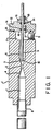
- FIG. 1 of the drawings A particular embodiment of the gas-liquid dispersion system of the invention, employing a venturi for gas-liquid acceleration and deacceleration purposes, is illustrated in Fig. 1 of the drawings, in which numeral 1 represents a gas- liquid dispersion body in which said venturi section is machined for use as described herein.
- the venturi comprises throat section 2 of minimum diameter, upstream converging section 3 and downstream diverging section 4.
- an inlet conduit 5 is provided for the introduction of a stream of liquid into dispersing body 1.
- the direction of said flow of liquid is perpendicular to upstream liquid flow conduit 6 through which the liquid is passed to upstream converging section 3 of the venturi, although those skilled in the art will appreciate that other configurations of liquid flow can be employed to minimize pressure losses in the system.
- the gas-liquid mixture discharged from the venturi through downstream diverging section 4 passes into downstream flow conduit 7 for passage from said dispersion body 1 through gas-liquid outlet line 8.
- gas inlet tube 9 is positioned within upstream liquid flow conduit 6 and extends into upstream converging section 3 of the venturi.
- Gas injection tip 10 is provided to facilitate the injection of gas into the liquid in said converging section 3 of the venturi.
- the upstream end of gas inlet tube 9 will be seen to extend through liquid chamber 11, into which liquid passes from liquid inlet 5 for discharge into upstream liquid flow conduit 6, and inlet cover plate 12 for communication with a source of supply for said gas.
- 0-rings are positioned between cover plate 12 and the upstream end portion of dispersion body 1 to provide a fluid-tight seal therebetween.
- 0-rings 14 are similarly provided to assure a fluid-tight seal between gas inlet take 9 and cover plate 12.
- Seal plates 15 and 16 are provided at the downstream end of said cover plate 12, respectively, to assure proper deformation of O-rings 14 into a fluid-type position.
- Suitable clamping means 17 and 18 are used to secure end plate 12 to said seal plates 15 and 16 and to dispersion body 1.
- any convenient means, manual, mechanical or otherwise, can be used to slide the gas inlet tube into any desired position relative to the position of the venturi.
- throat section 2 of the venturi was 0.19" in inside diameter and 0.36" long.
- the inside diameters of upstream and downstream flow conduits 6 and 7 were 0.63" and 0.83", respectively.
- Converging, section 3 was 0.72" long, and diverging section 4 was 1" long.
- the included angle of diverging section 4 of the venturi in this embodiment is 34°.
- the included angle of converging section 3 is 35°, with gas inlet tube 9 being 1/4" in inside diameter with gas injection tip 10 being 1/16" in inside diameter.
- Said gas injection tip 10 was positioned at about 50% of the distance from the upstream beginning of throat section 2 to the upstream end of converging section 3 of the venturi.
- the injection of one fluid into the other, typically gas into a liquid stream is carried out in close proximity to the flow constriction means used to create acceleration to supersonic velocities and deacceleration to sub-sonic velocities.
- the flow constriction means used to create acceleration to supersonic velocities and deacceleration to sub-sonic velocities.
- close proximity to the flow constriction means is intended to mean that the injection point, e.g. of gas into liquid, should be positioned at a distance not exceeding about one diameter in length upstream of the flow constriction means, based on the diameter of the flow conduit in which the orifice plate, reduced diameter section, venturi or other desired form of flow constriction means is positioned.
- the gas or other injection means should be positioned at a distance not more than that corresponding to one diameter in length from the upstream inlet end of converging section 3, based on the diameter of the flow conduit upstream of the venturi, i.e. upstream liquid flow conduit 6 in Fig. 1 of the drawings.
- gas inlet tube 9 can thus be positioned in liquid flow conduit 6 upstream of, but in close proximity to, the venturi, it is preferred that said gas inlet tube 9 (or, alternatively, a liquid inlet tube) be positioned within the converging section of the venturi itself.
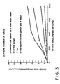
- the chart of Fig. 2 illustrates the effect of the positioning of tip 10 of gas inlet tube 9 on the oxygen mass transfer in an oxygen dispersion in water application carried out in a gas-liquid dispersion system essentially as shown in Fig. 1.
- the oxygen mass transfer is expressed in moles/(1-hr), and the distance of the tip of gas inlet tube 9 from the throat of the venturi is expressed in inches.
- the distance from the upstream beginning of throat 2 to the upstream end of converging section 3 was 1.81".
- the inside diameter of the flow conduit upstream of converging section 3 was 0.83".
- the positioning of tip 10 of gas inlet tube 9 can extend, in the practice of the invention. About 0.83" from the upstream end of converging section 3, i.e.
- included angles of the converging and diverging sections of the venturi can vary widely in the practice of the invention Those skilled in the art will appreciate that smaller, or shallower, included angles in the converging side of the venturi will result in lower amounts of pressure loss than if a larger or wider included angle is employed. Such smaller angled venturi sections are, however, corresponding longer in overall length and thus require more complex and costly machining in the manufacture thereof.
- the positioning of the gas injection means cannot be as close to the throat section of the venturi as may be desired, from a mass transfer viewpoint, in smaller angled venturi sections because the positioning of the gas injection means close to the throat of the venturi would tend to cut off, or seriously reduce, the flow of fluid to the venturi throat. It will be appreciated that such an arrangement would also result in a significant pressure loss within the venturi and in the operating cost of the system.
- the gas injection means can, if desired, be positioned closer to the venturi throat without cutting off, or seriously reducing, the fluid flow within the venturi.
- Such positioning of the gas injection means on a wider angled venturi will likewise result in a lesser pressure loss than that occurring if the same gas injection means were positioned close to the throat of a more shallow angled venturi.
- the gas injection means In general, it has been found convenient to position the gas injection means at about 50% of the distance from the throat to the inlet to the converging section of the venturi. It will be appreciated from the above, however, that the position of the gas injection means can be adjusted widely within the venturi, or in close proximity thereto, within the scope of the invention.
- gas injection means has been illustrated as being a gas inlet tube having a suitable gas injection tip, it is within the scope of the invention to employ a simple gas injection tube without incorporating a discharge tip or nozzle on the end portion thereof.
- gas injection means particularly as related to the movement of said gas injection means close to the venturi throat for enhanced mass transfer, it should be noted that it is desirable to make the gas injection tube as small and as streamlined as possible to reduce the pressure effects of its positioning at closer distances to the throat of the venturi.
- water was injected perpendicularly into the liquid flow conduit, and oxygen was injected into said liquid flow conduit in an axial manner in the vicinity of the water injection point.
- oxygen was again injected axially into the conduit, but through a fritted tip intended to enhance the initial dispersion of gas into the liquid.
- venturi device used in the practice of the invention and in the prior art practice was adapted to accelerate the velocity of the oxygen and water stream from less than the velocity of sound in said gas-liquid mixture to a supersonic velocity, with subsequent deacceleration to the sub-sonic range, while the configuration and in-line sparger were used in conjunction with a flow velocity at said sub-sonic range.
- the sub-sonic velocity was such as to provide an upstream flow velocity of about 0.73 meters per second of said gas-liquid mixture, with the operating pressure being about 10 psig.
- the oxygen mass transfer rate, in moles/1/hr was measured at various levels of oxygen addition, expressed in mg. of oxygen fed per kilogram of water, with the results being shown in Fig. 3 of the drawing.
- the mass transfer rate for oxygen in the stream of water was relatively low using the conventional tee device for mixing oxygen and water. Somewhat improved mass transfer was found to be obtained using an in-line sparger, particularly at higher levels of oxygen addition.
- higher oxygen mass transfer rates were achieved using a venturi device to accelerate the flow velocity from less than that of sound to one where the velocity exceeds that of sound in the gasliquid mixture, thereby enabling the oxygen bubbles to be very substantially broken up by the sonic shock wave affect accompanying the acceleration-deacceleration sequence to supersonic and back to sub-sonic velocity.
- the oxygen was added to the liquid stream at a distance corresponding to seven times the upstream diameter of the flow conduit from the upstream end of the venturi.
- the water velocity was about 0.73 meters per second, which is considerably less than that required for turbulent flow conditions adequate to disperse the oxygen uniformly in the water. Such relatively low water velocity is, however, desirable from an overall processing viewpoint
- the water velocity was also maintained at about 0.73 meters per second upstream of the venturi.
- the oxygen was combined with the water, in accordance with the practice of the invention, at a point about equal to the diameter of the water flow conduit in distance from the 0.16" diameter throat of the venturi.
- the oxygen injection point was at about 1/2 of the distance from the upstream beginning of the venturi throat to the upstream inlet to the converging section of the venturi. While the oxygen was thus combined with the water in the converging section of the venturi, a uniform dispersion of oxygen in water was not formed prior to the acceleration of the oxygen-water mixture to supersonic velocity as it passed to the throat section of the venturi.
- the advantageous results of the invention are, nevertheless, associated with the supersonic shock wave effect obtained as a result of the passage of the gas-liquid mixture at a velocity deaccelerating from supersonic velocity to sub-sonic velocity in the downstream diverging portion of the venturi, and/or accelerating from a sub-sonic velocity to a supersonic velocity in the upstream converging portion of the venturi in which the gas and liquid are mixed.
- a dual sonic shock wave effect i.e. upon deacceleration and upon initial acceleration of the gas-liquid dispersion in the venturi device or other form of constriction means used to create supersonic flow velocities, may possibly be realized, and any such dual shock effect is within the scope of the invention.
- Kieffer "Sound Speed in Liquid-Gas Mixtures: Water-Air and Water-Steam", Journal of Geophysical Research, Vol. 82, No. 20, July 10, 1977, pp. 2895-2903, confirm this effect which is used to advantage in practical commercial embodiments of the invention.
- the velocity of sound in an air/water mixture may be on the order of about 20 meters per second.
- the upstream velocity needed to achieve the results desired in the Garrett patent referred to above, i.e. less than that of the velocity of sound in the gas-liquid dispersion, but sufficient to enable the gas bubbles to remain uniformly dispersed by turbulence to avoid slug flow or stratification, is generally at least on the order of about 2 meters per second.
- the water or other liquid flow velocity upstream of the venturi can be maintained at a considerably lower level than that pertaining in the prior art approach of Garrett.
- water flow velocities of from about 0.3 to 1 meter per second can conveniently be employed, although higher or lower velocities can also be employed.
- the gas liquid dispersion process and system of the invention can be applied to a wide variety of gas liquid mixing operations.
- the invention can be conveniently employed not only in the dissolution of oxygen in water application referred to above, but in a variety of operations in which it may be desirable to dissolve air or oxygen, nitrogen, chlorine or other industrial gas in a variety of inorganic or organic liquids.
- the invention can be applied to advantage for gas-liquid reaction operations, as for the oxidation of iron present in aqueous solution or for the oxidation of organic liquids.
- the invention can also be employed for desirable dissolved gas stripping operations, as for the stripping of dissolved oxygen or other volatiles from liquids by the injection of nitrogen therein in accordance with the practice of the invention.
- the invention will thus be seen to provide a very desirable and beneficial advance in the art of dispersing gases in liquids.
- the invention enables the benefits of employing venturi or other form of flow constriction means to be more fully realized than was heretofore obtainable in the art.
- the invention further benefits the gas-liquid dispersion art by providing a desirable processing flexibility enabling the overall benefits of the invention to be more fully related to the practical requirements of any particular commercial application.
- the flow velocities employed in conjunction with the use of the constriction means can be maintained at a considerably lower level than in the prior art practice wherein turbulent flow conditions are required, the practical commercial feasibility of the invention is further enhanced, as is its benefit in a wide range of important commercial gas-liquid dispersion operations.
- the invention will thus be seen as serving to greatly increase the prospects for employing industrial gases in a wide variety of industrial activities in which the enhanced dispersion achieved in the practice of the invention provides a needed incentive for the desirably increased use of such gases in such industrial activities.
Applications Claiming Priority (2)
| Application Number | Priority Date | Filing Date | Title |
|---|---|---|---|
| US139573 | 1987-12-30 | ||
| US07/139,573 US4867918A (en) | 1987-12-30 | 1987-12-30 | Gas dispersion process and system |
Publications (3)
| Publication Number | Publication Date |
|---|---|
| EP0322925A2 true EP0322925A2 (fr) | 1989-07-05 |
| EP0322925A3 EP0322925A3 (fr) | 1989-08-30 |
| EP0322925B1 EP0322925B1 (fr) | 1996-09-25 |
Family
ID=22487319
Family Applications (1)
| Application Number | Title | Priority Date | Filing Date |
|---|---|---|---|
| EP88121913A Expired - Lifetime EP0322925B1 (fr) | 1987-12-30 | 1988-12-30 | Procédé pour disperser du gaz |
Country Status (9)
| Country | Link |
|---|---|
| US (1) | US4867918A (fr) |
| EP (1) | EP0322925B1 (fr) |
| JP (1) | JPH01288323A (fr) |
| KR (1) | KR940007731B1 (fr) |
| BR (1) | BR8807013A (fr) |
| CA (1) | CA1283651C (fr) |
| DE (1) | DE3855579T2 (fr) |
| ES (1) | ES2091748T3 (fr) |
| MX (1) | MX165709B (fr) |
Cited By (10)
| Publication number | Priority date | Publication date | Assignee | Title |
|---|---|---|---|---|
| EP0513739A2 (fr) * | 1991-05-13 | 1992-11-19 | Praxair Technology, Inc. | Désodorisation d'huile et/ou de graisse comestible avec un gaz inerte non-condensable et récupération d'un distillat d'un acide de haute qualité |
| EP0515767A1 (fr) * | 1991-05-03 | 1992-12-02 | Rio Linda Chemical Co., Inc. | Procédé de production de dioxyde de chlore |
| WO1999055450A1 (fr) * | 1998-04-28 | 1999-11-04 | Life International Products, Inc. | Appareil d'oxygenation, procede d'oxygenation d'un liquide utilisant ledit appareil, et applications |
| EP0995489A2 (fr) * | 1998-10-21 | 2000-04-26 | Praxair Technology, Inc. | Procédé pour accélérer des réactions rapides utilisant un réacteur tubulaire à haute intensité d' un écoulement piston |
| EP1064987A1 (fr) * | 1999-06-30 | 2001-01-03 | Praxair Technology, Inc. | Procédé de fabrication des liquides sursaturés d'oxygène |
| US6530895B1 (en) | 2000-01-25 | 2003-03-11 | Life International Products, Inc. | Oxygenating apparatus, method for oxygenating a liquid therewith, and applications thereof |
| FR3003769A1 (fr) * | 2013-04-02 | 2014-10-03 | Antea France | Systeme de stripeur dynamique |
| NO20150496A1 (en) * | 2015-04-23 | 2016-10-24 | Ozzo As | Mixing unit for a water-sterilizing device |
| EP3594173A1 (fr) | 2018-07-11 | 2020-01-15 | Riprup Company S.A. | Saturateur en ligne avec chambre de turbulence modulaire; distributeur de boissons avec ledit saturateur |
| DE102021001986A1 (de) | 2021-04-15 | 2022-10-20 | Messer Austria Gmbh | Vorrichtung und Verfahren zum Dispergieren von Gasen in Flüssigkeiten |
Families Citing this family (32)
| Publication number | Priority date | Publication date | Assignee | Title |
|---|---|---|---|---|
| US4931225A (en) * | 1987-12-30 | 1990-06-05 | Union Carbide Industrial Gases Technology Corporation | Method and apparatus for dispersing a gas into a liquid |
| US5356600A (en) * | 1990-09-24 | 1994-10-18 | Praxair Technology, Inc. | Oxygen enrichment method and system |
| US5061406A (en) * | 1990-09-25 | 1991-10-29 | Union Carbide Industrial Gases Technology Corporation | In-line gas/liquid dispersion |
| US5302325A (en) * | 1990-09-25 | 1994-04-12 | Praxair Technology, Inc. | In-line dispersion of gas in liquid |
| US5211916A (en) * | 1991-12-24 | 1993-05-18 | Praxair Technology, Inc. | Stripping system |
| DE9302862U1 (fr) * | 1993-02-26 | 1993-05-27 | Anton Steinecker Entwicklungs Gmbh & Co, 8050 Freising, De | |
| US5354459A (en) * | 1993-03-19 | 1994-10-11 | Jerry Smith | Apparatus and method for removing odorous sulfur compounds from potable water |
| US5730806A (en) * | 1993-08-30 | 1998-03-24 | The United States Of America As Represented By The Administrator Of The National Aeronautics & Space Administration | Gas-liquid supersonic cleaning and cleaning verification spray system |
| US6196525B1 (en) * | 1996-05-13 | 2001-03-06 | Universidad De Sevilla | Device and method for fluid aeration via gas forced through a liquid within an orifice of a pressure chamber |
| US5744040A (en) * | 1996-05-24 | 1998-04-28 | Sulfur-Tech Water Systems, Inc. | Apparatus and method for removing dissolved hydrogen sulfide from water |
| ID19133A (id) * | 1996-12-12 | 1998-06-18 | Praxair Technology Inc | Pengisian oksigen langsung kedalam reaktor-reaktor ruang gelembung |
| US6362367B2 (en) | 1998-04-21 | 2002-03-26 | Union Carbide Chemicals & Plastics Technology Corp. | Preparation of organic acids |
| US6103108A (en) * | 1998-09-24 | 2000-08-15 | Kohlenberg; Larry D. | Water treatment apparatus |
| US6165435A (en) * | 1998-12-24 | 2000-12-26 | Praxair Technology, Inc. | Method and production of nitric acid |
| FR2805008B1 (fr) * | 2000-02-16 | 2002-05-31 | Joseph Haiun | Compresseur termocinetique |
| US6623154B1 (en) * | 2000-04-12 | 2003-09-23 | Premier Wastewater International, Inc. | Differential injector |
| US6322055B1 (en) | 2000-10-02 | 2001-11-27 | Eco-Oxygen Technologies, Llc | Gas dissolving apparatus and method |
| DE10150931A1 (de) * | 2001-10-11 | 2003-04-30 | Lueder Gerking | Verbesserte Gemischbildung in Verbrennungskraftmaschinen |
| US6668556B2 (en) | 2002-04-18 | 2003-12-30 | Eco Oxygen Technologies, Llc. | Gas transfer energy recovery and effervescence prevention apparatus and method |
| US6877960B1 (en) | 2002-06-05 | 2005-04-12 | Flodesign, Inc. | Lobed convergent/divergent supersonic nozzle ejector system |
| US7174744B2 (en) * | 2002-08-20 | 2007-02-13 | American Air Liquide, Inc. | Method of improving the biocidal efficacy of dry ice |
| US7566397B2 (en) | 2004-02-09 | 2009-07-28 | Eco Oxygen Technologies, Llc | Superoxygenation of raw wastewater for odor/corrosion control |
| US7320749B2 (en) | 2004-02-09 | 2008-01-22 | Eco-Oxygen Technologies, Llc | Method and apparatus for control of a gas or chemical |
| US20070237671A1 (en) * | 2005-08-29 | 2007-10-11 | Yuan James T | Novel method of sanitizing target items using a moist sanitizing gas |
| DE102007023699B4 (de) * | 2007-05-22 | 2020-03-26 | Cremer Thermoprozeßanlagen-GmbH | Heiß Isostatische Presse und Verfahren zur Schnellkühlung einer Heiß Isostatischen Presse |
| US8118283B2 (en) * | 2007-09-21 | 2012-02-21 | Lanny Vlasak | Apparatus for aerating an aqueous solution |
| US9010734B1 (en) * | 2007-09-21 | 2015-04-21 | Todd Vlasak | Apparatus for aerating an aqueous solution |
| WO2011049215A1 (fr) * | 2009-10-22 | 2011-04-28 | エウレカ・ラボ株式会社 | Dispositif de traitement permettant de disperser, dissoudre, rendre compatibles ou émulsionner un gaz et un liquide ou deux liquides |
| KR101152433B1 (ko) * | 2010-04-23 | 2012-06-05 | 최정수 | 나노버블 발생노즐 및 이를 구비하는 구강 세정기 |
| KR101431584B1 (ko) * | 2012-12-18 | 2014-08-20 | 주식회사 엘크린시스템 | 다용도 초미세기포 발생기 |
| KR101424979B1 (ko) * | 2013-05-24 | 2014-08-13 | 한국기계연구원 | 이상유동 유체의 유효밀도 측정방법 및 기포 함유율 측정방법 |
| CN113856504B (zh) * | 2021-10-11 | 2024-02-20 | 扬州凯芬机械有限公司 | 一种卫生型气液混合装置 |
Citations (4)
| Publication number | Priority date | Publication date | Assignee | Title |
|---|---|---|---|---|
| GB808070A (en) * | 1956-05-29 | 1959-01-28 | Cyril Robert Levis | An injector device for impregnating liquids with gases or for mixing liquids |
| US3112988A (en) * | 1960-02-26 | 1963-12-03 | Sheil Oil Company | Mixing gases at supersonic velocity |
| CA1033078A (fr) * | 1973-07-09 | 1978-06-13 | Lyle D. Hemperly | Methode et materiel supersoniques pour la production de petites bulles |
| EP0152202A2 (fr) * | 1984-01-24 | 1985-08-21 | The BOC Group plc | Dissolution d'un gaz dans un liquide |
Family Cites Families (12)
| Publication number | Priority date | Publication date | Assignee | Title |
|---|---|---|---|---|
| US2060557A (en) * | 1934-07-25 | 1936-11-10 | Ind Patents Corp | Mixing device |
| US2413102A (en) * | 1941-11-25 | 1946-12-24 | American Viscose Corp | Degasifier |
| GB1144463A (en) * | 1965-09-28 | 1969-03-05 | Licencia Talalmanyokat | Flotation equipment |
| US3371618A (en) * | 1966-02-18 | 1968-03-05 | Chambers John | Pump |
| DE1517502A1 (de) * | 1966-12-31 | 1969-05-22 | Noll Gmbh Maschinenfabrik W | Strahlapparat zum Saettigen von Wasser mit gasfoermiger CO2 |
| FR2084292A5 (fr) * | 1970-03-06 | 1971-12-17 | Dresser Ind | |
| DE2053991C3 (de) * | 1970-11-03 | 1975-11-27 | Joseph 8000 Muenchen Plannerer | Vergaser fur Brennkraftmaschinen |
| FR2122682A5 (fr) * | 1971-01-20 | 1972-09-01 | Siderurgie Fse Inst Rech | |
| US3734111A (en) * | 1971-12-20 | 1973-05-22 | Phillips Petroleum Co | Apparatus for in-line mixing of fluids |
| JPS5473361A (en) * | 1977-11-22 | 1979-06-12 | Clevepak Corp | Apparatus for mixing gas and fluid and method of operating same |
| US4226719A (en) * | 1978-07-10 | 1980-10-07 | Woltman Robert B | Treating device for large bodies of water |
| US4261347A (en) * | 1979-12-06 | 1981-04-14 | Jacuzzi Bros., Inc. | Hydromassage fitting for tubs, spas and pools |
-
1987
- 1987-12-30 US US07/139,573 patent/US4867918A/en not_active Expired - Lifetime
-
1988
- 1988-12-29 JP JP63335728A patent/JPH01288323A/ja active Pending
- 1988-12-30 MX MX014403A patent/MX165709B/es unknown
- 1988-12-30 CA CA000587334A patent/CA1283651C/fr not_active Expired - Lifetime
- 1988-12-30 BR BR888807013A patent/BR8807013A/pt not_active IP Right Cessation
- 1988-12-30 DE DE3855579T patent/DE3855579T2/de not_active Expired - Fee Related
- 1988-12-30 KR KR1019880018226A patent/KR940007731B1/ko not_active IP Right Cessation
- 1988-12-30 EP EP88121913A patent/EP0322925B1/fr not_active Expired - Lifetime
- 1988-12-30 ES ES88121913T patent/ES2091748T3/es not_active Expired - Lifetime
Patent Citations (4)
| Publication number | Priority date | Publication date | Assignee | Title |
|---|---|---|---|---|
| GB808070A (en) * | 1956-05-29 | 1959-01-28 | Cyril Robert Levis | An injector device for impregnating liquids with gases or for mixing liquids |
| US3112988A (en) * | 1960-02-26 | 1963-12-03 | Sheil Oil Company | Mixing gases at supersonic velocity |
| CA1033078A (fr) * | 1973-07-09 | 1978-06-13 | Lyle D. Hemperly | Methode et materiel supersoniques pour la production de petites bulles |
| EP0152202A2 (fr) * | 1984-01-24 | 1985-08-21 | The BOC Group plc | Dissolution d'un gaz dans un liquide |
Cited By (16)
| Publication number | Priority date | Publication date | Assignee | Title |
|---|---|---|---|---|
| EP0515767A1 (fr) * | 1991-05-03 | 1992-12-02 | Rio Linda Chemical Co., Inc. | Procédé de production de dioxyde de chlore |
| EP0513739A3 (en) * | 1991-05-13 | 1992-12-16 | Union Carbide Industrial Gases Technology Corporation | Deodorizing edible oil and/or fat with non-condensible inert gas and recovering a high quality fatty acid distillate |
| EP0513739A2 (fr) * | 1991-05-13 | 1992-11-19 | Praxair Technology, Inc. | Désodorisation d'huile et/ou de graisse comestible avec un gaz inerte non-condensable et récupération d'un distillat d'un acide de haute qualité |
| US6120008A (en) * | 1998-04-28 | 2000-09-19 | Life International Products, Inc. | Oxygenating apparatus, method for oxygenating a liquid therewith, and applications thereof |
| WO1999055450A1 (fr) * | 1998-04-28 | 1999-11-04 | Life International Products, Inc. | Appareil d'oxygenation, procede d'oxygenation d'un liquide utilisant ledit appareil, et applications |
| US6279882B1 (en) | 1998-04-28 | 2001-08-28 | Life International Products, Inc. | Oxygenating apparatus, method for oxygenating a liquid therewith, and applications thereof |
| EP0995489A2 (fr) * | 1998-10-21 | 2000-04-26 | Praxair Technology, Inc. | Procédé pour accélérer des réactions rapides utilisant un réacteur tubulaire à haute intensité d' un écoulement piston |
| EP0995489A3 (fr) * | 1998-10-21 | 2000-07-26 | Praxair Technology, Inc. | Procédé pour accélérer des réactions rapides utilisant un réacteur tubulaire à haute intensité d' un écoulement piston |
| EP1064987A1 (fr) * | 1999-06-30 | 2001-01-03 | Praxair Technology, Inc. | Procédé de fabrication des liquides sursaturés d'oxygène |
| US6530895B1 (en) | 2000-01-25 | 2003-03-11 | Life International Products, Inc. | Oxygenating apparatus, method for oxygenating a liquid therewith, and applications thereof |
| FR3003769A1 (fr) * | 2013-04-02 | 2014-10-03 | Antea France | Systeme de stripeur dynamique |
| NO20150496A1 (en) * | 2015-04-23 | 2016-10-24 | Ozzo As | Mixing unit for a water-sterilizing device |
| EP3594173A1 (fr) | 2018-07-11 | 2020-01-15 | Riprup Company S.A. | Saturateur en ligne avec chambre de turbulence modulaire; distributeur de boissons avec ledit saturateur |
| EP3594174A1 (fr) | 2018-07-11 | 2020-01-15 | RIPRUP Company S.A. | Dispositif de carbonisation de type flux présentant de propriétés de désinfection et distributeur de boissons doté d'un tel dispositif |
| DE102021001986A1 (de) | 2021-04-15 | 2022-10-20 | Messer Austria Gmbh | Vorrichtung und Verfahren zum Dispergieren von Gasen in Flüssigkeiten |
| WO2022218636A1 (fr) | 2021-04-15 | 2022-10-20 | Messer Se & Co. Kgaa | Dispositif et procédé de dispersion de gaz dans des liquides |
Also Published As
| Publication number | Publication date |
|---|---|
| CA1283651C (fr) | 1991-04-30 |
| US4867918A (en) | 1989-09-19 |
| KR890009457A (ko) | 1989-08-02 |
| DE3855579D1 (de) | 1996-10-31 |
| KR940007731B1 (ko) | 1994-08-24 |
| BR8807013A (pt) | 1989-09-05 |
| DE3855579T2 (de) | 1997-04-17 |
| EP0322925B1 (fr) | 1996-09-25 |
| JPH01288323A (ja) | 1989-11-20 |
| ES2091748T3 (es) | 1996-11-16 |
| MX165709B (es) | 1992-12-01 |
| EP0322925A3 (fr) | 1989-08-30 |
Similar Documents
| Publication | Publication Date | Title |
|---|---|---|
| EP0322925A2 (fr) | Procédé pour disperser du gaz | |
| EP0477845B1 (fr) | Dispersion de gaz dans un liquide en ligne | |
| EP0477846B1 (fr) | Dispersion gaz/liquide en ligne | |
| US4639340A (en) | Dissolving gas in a liquid | |
| US4633909A (en) | Apparatus for the rapid in-line mixing of two fluids | |
| US4931225A (en) | Method and apparatus for dispersing a gas into a liquid | |
| CA2312740C (fr) | Melangeur-injecteurs | |
| CA2256531C (fr) | Melangeur sans moteur | |
| US4328107A (en) | Process and apparatus for forming dispersions | |
| US4573803A (en) | Injection nozzle | |
| IL40493A (en) | Method for treating animal waste with oxygen | |
| JP4270867B2 (ja) | 反応器への開始剤給送装置 | |
| IE901005L (en) | Dissolution of gas | |
| EP3281690B1 (fr) | Installation et processus de réaction ou de mélange de liquide/gaz | |
| CA1257195A (fr) | Oxygenation d'un liquide | |
| EP1501626B1 (fr) | Dispositif et procede de creation de cavitation hydrodynamique dans des fluides | |
| US4840751A (en) | Process for contacting gases with liquids | |
| EP0383556B1 (fr) | Méthode pour couper et appareil | |
| JPS61149232A (ja) | 混合装置 | |
| WO2001062392A1 (fr) | Dispositif de buse d'injection destine a des recipients de reaction aeres et procede de fonctionnement de tels recipients | |
| SU698641A1 (ru) | Струйный аппарат | |
| CN117797675A (zh) | 气液喷射装置和制备方法 | |
| GB1595191A (en) | Treatment with oxygen of sewage in sewers | |
| JPS62251074A (ja) | スパイラルフロ−によるブラスト方法とその装置 |
Legal Events
| Date | Code | Title | Description |
|---|---|---|---|
| PUAI | Public reference made under article 153(3) epc to a published international application that has entered the european phase |
Free format text: ORIGINAL CODE: 0009012 |
|
| AK | Designated contracting states |
Kind code of ref document: A2 Designated state(s): BE DE ES FR GB IT NL |
|
| PUAL | Search report despatched |
Free format text: ORIGINAL CODE: 0009013 |
|
| RHK1 | Main classification (correction) |
Ipc: B01F 3/04 |
|
| AK | Designated contracting states |
Kind code of ref document: A3 Designated state(s): BE DE ES FR GB IT NL |
|
| 17P | Request for examination filed |
Effective date: 19890908 |
|
| 17Q | First examination report despatched |
Effective date: 19910430 |
|
| RAP1 | Party data changed (applicant data changed or rights of an application transferred) |
Owner name: PRAXAIR TECHNOLOGY, INC. |
|
| GRAG | Despatch of communication of intention to grant |
Free format text: ORIGINAL CODE: EPIDOS AGRA |
|
| GRAH | Despatch of communication of intention to grant a patent |
Free format text: ORIGINAL CODE: EPIDOS IGRA |
|
| GRAH | Despatch of communication of intention to grant a patent |
Free format text: ORIGINAL CODE: EPIDOS IGRA |
|
| GRAA | (expected) grant |
Free format text: ORIGINAL CODE: 0009210 |
|
| ITF | It: translation for a ep patent filed |
Owner name: BARZANO' E ZANARDO ROMA S.P.A. |
|
| AK | Designated contracting states |
Kind code of ref document: B1 Designated state(s): BE DE ES FR GB IT NL |
|
| REF | Corresponds to: |
Ref document number: 3855579 Country of ref document: DE Date of ref document: 19961031 |
|
| ET | Fr: translation filed | ||
| REG | Reference to a national code |
Ref country code: ES Ref legal event code: FG2A Ref document number: 2091748 Country of ref document: ES Kind code of ref document: T3 |
|
| PG25 | Lapsed in a contracting state [announced via postgrant information from national office to epo] |
Ref country code: GB Effective date: 19961230 |
|
| PLBE | No opposition filed within time limit |
Free format text: ORIGINAL CODE: 0009261 |
|
| STAA | Information on the status of an ep patent application or granted ep patent |
Free format text: STATUS: NO OPPOSITION FILED WITHIN TIME LIMIT |
|
| GBPC | Gb: european patent ceased through non-payment of renewal fee |
Effective date: 19961230 |
|
| 26N | No opposition filed | ||
| PGFP | Annual fee paid to national office [announced via postgrant information from national office to epo] |
Ref country code: NL Payment date: 20001130 Year of fee payment: 13 |
|
| PGFP | Annual fee paid to national office [announced via postgrant information from national office to epo] |
Ref country code: DE Payment date: 20011204 Year of fee payment: 14 |
|
| PGFP | Annual fee paid to national office [announced via postgrant information from national office to epo] |
Ref country code: BE Payment date: 20011224 Year of fee payment: 14 |
|
| PG25 | Lapsed in a contracting state [announced via postgrant information from national office to epo] |
Ref country code: NL Free format text: LAPSE BECAUSE OF NON-PAYMENT OF DUE FEES Effective date: 20020701 |
|
| NLV4 | Nl: lapsed or anulled due to non-payment of the annual fee |
Effective date: 20020701 |
|
| PGFP | Annual fee paid to national office [announced via postgrant information from national office to epo] |
Ref country code: FR Payment date: 20021127 Year of fee payment: 15 |
|
| PG25 | Lapsed in a contracting state [announced via postgrant information from national office to epo] |
Ref country code: BE Free format text: LAPSE BECAUSE OF NON-PAYMENT OF DUE FEES Effective date: 20021231 |
|
| PGFP | Annual fee paid to national office [announced via postgrant information from national office to epo] |
Ref country code: ES Payment date: 20030109 Year of fee payment: 15 |
|
| BERE | Be: lapsed |
Owner name: *PRAXAIR TECHNOLOGY INC. Effective date: 20021231 |
|
| PG25 | Lapsed in a contracting state [announced via postgrant information from national office to epo] |
Ref country code: DE Free format text: LAPSE BECAUSE OF NON-PAYMENT OF DUE FEES Effective date: 20030701 |
|
| PG25 | Lapsed in a contracting state [announced via postgrant information from national office to epo] |
Ref country code: ES Free format text: LAPSE BECAUSE OF NON-PAYMENT OF DUE FEES Effective date: 20031231 |
|
| PG25 | Lapsed in a contracting state [announced via postgrant information from national office to epo] |
Ref country code: FR Free format text: LAPSE BECAUSE OF NON-PAYMENT OF DUE FEES Effective date: 20040831 |
|
| REG | Reference to a national code |
Ref country code: FR Ref legal event code: ST |
|
| REG | Reference to a national code |
Ref country code: ES Ref legal event code: FD2A Effective date: 20031231 |
|
| PG25 | Lapsed in a contracting state [announced via postgrant information from national office to epo] |
Ref country code: IT Free format text: LAPSE BECAUSE OF NON-PAYMENT OF DUE FEES;WARNING: LAPSES OF ITALIAN PATENTS WITH EFFECTIVE DATE BEFORE 2007 MAY HAVE OCCURRED AT ANY TIME BEFORE 2007. THE CORRECT EFFECTIVE DATE MAY BE DIFFERENT FROM THE ONE RECORDED. Effective date: 20051230 |