EP3593843B1 - Add-on modul mit mechanischem dosis schalter - Google Patents
Add-on modul mit mechanischem dosis schalter Download PDFInfo
- Publication number
- EP3593843B1 EP3593843B1 EP19189194.4A EP19189194A EP3593843B1 EP 3593843 B1 EP3593843 B1 EP 3593843B1 EP 19189194 A EP19189194 A EP 19189194A EP 3593843 B1 EP3593843 B1 EP 3593843B1
- Authority
- EP
- European Patent Office
- Prior art keywords
- dose
- injection device
- supplemental
- state
- electromechanical switch
- Prior art date
- Legal status (The legal status is an assumption and is not a legal conclusion. Google has not performed a legal analysis and makes no representation as to the accuracy of the status listed.)
- Active
Links
- 230000000153 supplemental effect Effects 0.000 title claims description 184
- 239000007924 injection Substances 0.000 claims description 194
- 238000002347 injection Methods 0.000 claims description 194
- 239000003814 drug Substances 0.000 claims description 46
- 238000012015 optical character recognition Methods 0.000 claims description 25
- 230000008859 change Effects 0.000 claims description 21
- 230000003247 decreasing effect Effects 0.000 claims description 7
- 230000004044 response Effects 0.000 claims description 4
- NOESYZHRGYRDHS-UHFFFAOYSA-N insulin Chemical compound N1C(=O)C(NC(=O)C(CCC(N)=O)NC(=O)C(CCC(O)=O)NC(=O)C(C(C)C)NC(=O)C(NC(=O)CN)C(C)CC)CSSCC(C(NC(CO)C(=O)NC(CC(C)C)C(=O)NC(CC=2C=CC(O)=CC=2)C(=O)NC(CCC(N)=O)C(=O)NC(CC(C)C)C(=O)NC(CCC(O)=O)C(=O)NC(CC(N)=O)C(=O)NC(CC=2C=CC(O)=CC=2)C(=O)NC(CSSCC(NC(=O)C(C(C)C)NC(=O)C(CC(C)C)NC(=O)C(CC=2C=CC(O)=CC=2)NC(=O)C(CC(C)C)NC(=O)C(C)NC(=O)C(CCC(O)=O)NC(=O)C(C(C)C)NC(=O)C(CC(C)C)NC(=O)C(CC=2NC=NC=2)NC(=O)C(CO)NC(=O)CNC2=O)C(=O)NCC(=O)NC(CCC(O)=O)C(=O)NC(CCCNC(N)=N)C(=O)NCC(=O)NC(CC=3C=CC=CC=3)C(=O)NC(CC=3C=CC=CC=3)C(=O)NC(CC=3C=CC(O)=CC=3)C(=O)NC(C(C)O)C(=O)N3C(CCC3)C(=O)NC(CCCCN)C(=O)NC(C)C(O)=O)C(=O)NC(CC(N)=O)C(O)=O)=O)NC(=O)C(C(C)CC)NC(=O)C(CO)NC(=O)C(C(C)O)NC(=O)C1CSSCC2NC(=O)C(CC(C)C)NC(=O)C(NC(=O)C(CCC(N)=O)NC(=O)C(CC(N)=O)NC(=O)C(NC(=O)C(N)CC=1C=CC=CC=1)C(C)C)CC1=CN=CN1 NOESYZHRGYRDHS-UHFFFAOYSA-N 0.000 description 62
- 239000008280 blood Substances 0.000 description 35
- 210000004369 blood Anatomy 0.000 description 35
- WQZGKKKJIJFFOK-GASJEMHNSA-N Glucose Natural products OC[C@H]1OC(O)[C@H](O)[C@@H](O)[C@@H]1O WQZGKKKJIJFFOK-GASJEMHNSA-N 0.000 description 33
- 239000008103 glucose Substances 0.000 description 33
- 102000004877 Insulin Human genes 0.000 description 32
- 108090001061 Insulin Proteins 0.000 description 32
- 229940125396 insulin Drugs 0.000 description 31
- 230000007704 transition Effects 0.000 description 31
- 238000004891 communication Methods 0.000 description 24
- 238000012544 monitoring process Methods 0.000 description 24
- 238000001514 detection method Methods 0.000 description 16
- 238000000034 method Methods 0.000 description 16
- 230000003287 optical effect Effects 0.000 description 16
- 230000005540 biological transmission Effects 0.000 description 15
- 230000009471 action Effects 0.000 description 10
- 101000579646 Penaeus vannamei Penaeidin-1 Proteins 0.000 description 8
- 230000006870 function Effects 0.000 description 6
- 229940127560 insulin pen Drugs 0.000 description 6
- 230000008569 process Effects 0.000 description 6
- RCHHVVGSTHAVPF-ZPHPLDECSA-N apidra Chemical compound C([C@@H](C(=O)N[C@@H](CC(C)C)C(=O)N[C@H]1CSSC[C@H]2C(=O)N[C@H](C(=O)N[C@@H](CO)C(=O)N[C@H](C(=O)N[C@H](C(N[C@@H](CO)C(=O)N[C@@H](CC(C)C)C(=O)N[C@@H](CC=3C=CC(O)=CC=3)C(=O)N[C@@H](CCC(N)=O)C(=O)N[C@@H](CC(C)C)C(=O)N[C@@H](CCC(O)=O)C(=O)N[C@@H](CC(N)=O)C(=O)N[C@@H](CC=3C=CC(O)=CC=3)C(=O)N[C@@H](CSSC[C@H](NC(=O)[C@H](C(C)C)NC(=O)[C@H](CC(C)C)NC(=O)[C@H](CC=3C=CC(O)=CC=3)NC(=O)[C@H](CC(C)C)NC(=O)[C@H](C)NC(=O)[C@H](CCC(O)=O)NC(=O)[C@H](C(C)C)NC(=O)[C@H](CC(C)C)NC(=O)[C@H](CC=3N=CNC=3)NC(=O)[C@H](CO)NC(=O)CNC1=O)C(=O)NCC(=O)N[C@@H](CCC(O)=O)C(=O)N[C@@H](CCCNC(N)=N)C(=O)NCC(=O)N[C@@H](CC=1C=CC=CC=1)C(=O)N[C@@H](CC=1C=CC=CC=1)C(=O)N[C@@H](CC=1C=CC(O)=CC=1)C(=O)N[C@@H]([C@@H](C)O)C(=O)N1[C@@H](CCC1)C(=O)N[C@@H](CCC(O)=O)C(=O)N[C@@H]([C@@H](C)O)C(O)=O)C(=O)N[C@@H](CC(N)=O)C(O)=O)=O)CSSC[C@@H](C(N2)=O)NC(=O)[C@H](CCC(N)=O)NC(=O)[C@H](CCC(O)=O)NC(=O)[C@H](C(C)C)NC(=O)[C@@H](NC(=O)CN)[C@@H](C)CC)[C@@H](C)CC)[C@@H](C)O)NC(=O)[C@H](CCC(N)=O)NC(=O)[C@H](CCCCN)NC(=O)[C@@H](NC(=O)[C@@H](N)CC=1C=CC=CC=1)C(C)C)C1=CNC=N1 RCHHVVGSTHAVPF-ZPHPLDECSA-N 0.000 description 5
- 229940112930 apidra Drugs 0.000 description 5
- 108700039926 insulin glulisine Proteins 0.000 description 5
- 230000013011 mating Effects 0.000 description 5
- 238000003860 storage Methods 0.000 description 5
- 230000008901 benefit Effects 0.000 description 4
- 238000010586 diagram Methods 0.000 description 4
- 238000003825 pressing Methods 0.000 description 4
- 238000012545 processing Methods 0.000 description 3
- 238000012546 transfer Methods 0.000 description 3
- 108010057186 Insulin Glargine Proteins 0.000 description 2
- COCFEDIXXNGUNL-RFKWWTKHSA-N Insulin glargine Chemical compound C([C@@H](C(=O)N[C@@H](CC(C)C)C(=O)N[C@H]1CSSC[C@H]2C(=O)N[C@H](C(=O)N[C@@H](CO)C(=O)N[C@H](C(=O)N[C@H](C(N[C@@H](CO)C(=O)N[C@@H](CC(C)C)C(=O)N[C@@H](CC=3C=CC(O)=CC=3)C(=O)N[C@@H](CCC(N)=O)C(=O)N[C@@H](CC(C)C)C(=O)N[C@@H](CCC(O)=O)C(=O)N[C@@H](CC(N)=O)C(=O)N[C@@H](CC=3C=CC(O)=CC=3)C(=O)N[C@@H](CSSC[C@H](NC(=O)[C@H](C(C)C)NC(=O)[C@H](CC(C)C)NC(=O)[C@H](CC=3C=CC(O)=CC=3)NC(=O)[C@H](CC(C)C)NC(=O)[C@H](C)NC(=O)[C@H](CCC(O)=O)NC(=O)[C@H](C(C)C)NC(=O)[C@H](CC(C)C)NC(=O)[C@H](CC=3NC=NC=3)NC(=O)[C@H](CO)NC(=O)CNC1=O)C(=O)NCC(=O)N[C@@H](CCC(O)=O)C(=O)N[C@@H](CCCNC(N)=N)C(=O)NCC(=O)N[C@@H](CC=1C=CC=CC=1)C(=O)N[C@@H](CC=1C=CC=CC=1)C(=O)N[C@@H](CC=1C=CC(O)=CC=1)C(=O)N[C@@H]([C@@H](C)O)C(=O)N1[C@@H](CCC1)C(=O)N[C@@H](CCCCN)C(=O)N[C@@H]([C@@H](C)O)C(=O)N[C@@H](CCCNC(N)=N)C(=O)N[C@@H](CCCNC(N)=N)C(O)=O)C(=O)NCC(O)=O)=O)CSSC[C@@H](C(N2)=O)NC(=O)[C@H](CCC(N)=O)NC(=O)[C@H](CCC(O)=O)NC(=O)[C@H](C(C)C)NC(=O)[C@@H](NC(=O)CN)[C@@H](C)CC)[C@@H](C)CC)[C@@H](C)O)NC(=O)[C@H](CCC(N)=O)NC(=O)[C@H](CC(N)=O)NC(=O)[C@@H](NC(=O)[C@@H](N)CC=1C=CC=CC=1)C(C)C)C1=CN=CN1 COCFEDIXXNGUNL-RFKWWTKHSA-N 0.000 description 2
- 238000004364 calculation method Methods 0.000 description 2
- 238000004590 computer program Methods 0.000 description 2
- 238000009826 distribution Methods 0.000 description 2
- 229940060975 lantus Drugs 0.000 description 2
- 239000007788 liquid Substances 0.000 description 2
- 238000004519 manufacturing process Methods 0.000 description 2
- 238000012986 modification Methods 0.000 description 2
- 230000004048 modification Effects 0.000 description 2
- 230000009467 reduction Effects 0.000 description 2
- 239000000523 sample Substances 0.000 description 2
- HTTJABKRGRZYRN-UHFFFAOYSA-N Heparin Chemical compound OC1C(NC(=O)C)C(O)OC(COS(O)(=O)=O)C1OC1C(OS(O)(=O)=O)C(O)C(OC2C(C(OS(O)(=O)=O)C(OC3C(C(O)C(O)C(O3)C(O)=O)OS(O)(=O)=O)C(CO)O2)NS(O)(=O)=O)C(C(O)=O)O1 HTTJABKRGRZYRN-UHFFFAOYSA-N 0.000 description 1
- 206010067584 Type 1 diabetes mellitus Diseases 0.000 description 1
- 239000000853 adhesive Substances 0.000 description 1
- 230000001070 adhesive effect Effects 0.000 description 1
- 238000013459 approach Methods 0.000 description 1
- 230000009286 beneficial effect Effects 0.000 description 1
- 239000012876 carrier material Substances 0.000 description 1
- POIUWJQBRNEFGX-XAMSXPGMSA-N cathelicidin Chemical compound C([C@@H](C(=O)N[C@@H](CCCNC(N)=N)C(=O)N[C@@H](CCCCN)C(=O)N[C@@H](CO)C(=O)N[C@@H](CCCCN)C(=O)N[C@@H](CCC(O)=O)C(=O)N[C@@H](CCCCN)C(=O)N[C@@H]([C@@H](C)CC)C(=O)NCC(=O)N[C@@H](CCCCN)C(=O)N[C@@H](CCC(O)=O)C(=O)N[C@@H](CC=1C=CC=CC=1)C(=O)N[C@@H](CCCCN)C(=O)N[C@@H](CCCNC(N)=N)C(=O)N[C@@H]([C@@H](C)CC)C(=O)N[C@@H](C(C)C)C(=O)N[C@@H](CCC(N)=O)C(=O)N[C@@H](CCCNC(N)=N)C(=O)N[C@@H]([C@@H](C)CC)C(=O)N[C@@H](CCCCN)C(=O)N[C@@H](CC(O)=O)C(=O)N[C@@H](CC=1C=CC=CC=1)C(=O)N[C@@H](CC(C)C)C(=O)N[C@@H](CCCNC(N)=N)C(=O)N[C@@H](CC(N)=O)C(=O)N[C@@H](CC(C)C)C(=O)N[C@@H](C(C)C)C(=O)N1[C@@H](CCC1)C(=O)N[C@@H](CCCNC(N)=N)C(=O)N[C@@H]([C@@H](C)O)C(=O)N[C@@H](CCC(O)=O)C(=O)N[C@@H](CO)C(O)=O)NC(=O)[C@H](CC=1C=CC=CC=1)NC(=O)[C@H](CC(O)=O)NC(=O)CNC(=O)[C@H](CC(C)C)NC(=O)[C@@H](N)CC(C)C)C1=CC=CC=C1 POIUWJQBRNEFGX-XAMSXPGMSA-N 0.000 description 1
- 238000010276 construction Methods 0.000 description 1
- 238000012937 correction Methods 0.000 description 1
- 230000001419 dependent effect Effects 0.000 description 1
- 238000013461 design Methods 0.000 description 1
- 206010012601 diabetes mellitus Diseases 0.000 description 1
- 230000004069 differentiation Effects 0.000 description 1
- 201000010099 disease Diseases 0.000 description 1
- 208000037265 diseases, disorders, signs and symptoms Diseases 0.000 description 1
- 238000011156 evaluation Methods 0.000 description 1
- 239000000835 fiber Substances 0.000 description 1
- 229960002897 heparin Drugs 0.000 description 1
- 229920000669 heparin Polymers 0.000 description 1
- 238000005286 illumination Methods 0.000 description 1
- 238000010191 image analysis Methods 0.000 description 1
- 230000001771 impaired effect Effects 0.000 description 1
- 230000000977 initiatory effect Effects 0.000 description 1
- 239000004026 insulin derivative Substances 0.000 description 1
- 239000004973 liquid crystal related substance Substances 0.000 description 1
- 239000000463 material Substances 0.000 description 1
- 238000005259 measurement Methods 0.000 description 1
- 238000010606 normalization Methods 0.000 description 1
- 238000003909 pattern recognition Methods 0.000 description 1
- 230000000737 periodic effect Effects 0.000 description 1
- 229920003229 poly(methyl methacrylate) Polymers 0.000 description 1
- 239000004926 polymethyl methacrylate Substances 0.000 description 1
- 230000002250 progressing effect Effects 0.000 description 1
- 230000000717 retained effect Effects 0.000 description 1
- 230000005236 sound signal Effects 0.000 description 1
- 238000001228 spectrum Methods 0.000 description 1
- 239000012899 standard injection Substances 0.000 description 1
- 230000001225 therapeutic effect Effects 0.000 description 1
- 238000004448 titration Methods 0.000 description 1
- 208000001072 type 2 diabetes mellitus Diseases 0.000 description 1
Images


Classifications
-
- A—HUMAN NECESSITIES
- A61—MEDICAL OR VETERINARY SCIENCE; HYGIENE
- A61M—DEVICES FOR INTRODUCING MEDIA INTO, OR ONTO, THE BODY; DEVICES FOR TRANSDUCING BODY MEDIA OR FOR TAKING MEDIA FROM THE BODY; DEVICES FOR PRODUCING OR ENDING SLEEP OR STUPOR
- A61M5/00—Devices for bringing media into the body in a subcutaneous, intra-vascular or intramuscular way; Accessories therefor, e.g. filling or cleaning devices, arm-rests
- A61M5/178—Syringes
- A61M5/31—Details
- A61M5/315—Pistons; Piston-rods; Guiding, blocking or restricting the movement of the rod or piston; Appliances on the rod for facilitating dosing ; Dosing mechanisms
- A61M5/31533—Dosing mechanisms, i.e. setting a dose
- A61M5/31545—Setting modes for dosing
- A61M5/31548—Mechanically operated dose setting member
- A61M5/3155—Mechanically operated dose setting member by rotational movement of dose setting member, e.g. during setting or filling of a syringe
-
- G—PHYSICS
- G01—MEASURING; TESTING
- G01D—MEASURING NOT SPECIALLY ADAPTED FOR A SPECIFIC VARIABLE; ARRANGEMENTS FOR MEASURING TWO OR MORE VARIABLES NOT COVERED IN A SINGLE OTHER SUBCLASS; TARIFF METERING APPARATUS; MEASURING OR TESTING NOT OTHERWISE PROVIDED FOR
- G01D5/00—Mechanical means for transferring the output of a sensing member; Means for converting the output of a sensing member to another variable where the form or nature of the sensing member does not constrain the means for converting; Transducers not specially adapted for a specific variable
- G01D5/26—Mechanical means for transferring the output of a sensing member; Means for converting the output of a sensing member to another variable where the form or nature of the sensing member does not constrain the means for converting; Transducers not specially adapted for a specific variable characterised by optical transfer means, i.e. using infrared, visible, or ultraviolet light
-
- G—PHYSICS
- G01—MEASURING; TESTING
- G01F—MEASURING VOLUME, VOLUME FLOW, MASS FLOW OR LIQUID LEVEL; METERING BY VOLUME
- G01F22/00—Methods or apparatus for measuring volume of fluids or fluent solid material, not otherwise provided for
-
- G—PHYSICS
- G16—INFORMATION AND COMMUNICATION TECHNOLOGY [ICT] SPECIALLY ADAPTED FOR SPECIFIC APPLICATION FIELDS
- G16H—HEALTHCARE INFORMATICS, i.e. INFORMATION AND COMMUNICATION TECHNOLOGY [ICT] SPECIALLY ADAPTED FOR THE HANDLING OR PROCESSING OF MEDICAL OR HEALTHCARE DATA
- G16H20/00—ICT specially adapted for therapies or health-improving plans, e.g. for handling prescriptions, for steering therapy or for monitoring patient compliance
- G16H20/10—ICT specially adapted for therapies or health-improving plans, e.g. for handling prescriptions, for steering therapy or for monitoring patient compliance relating to drugs or medications, e.g. for ensuring correct administration to patients
- G16H20/17—ICT specially adapted for therapies or health-improving plans, e.g. for handling prescriptions, for steering therapy or for monitoring patient compliance relating to drugs or medications, e.g. for ensuring correct administration to patients delivered via infusion or injection
-
- G—PHYSICS
- G16—INFORMATION AND COMMUNICATION TECHNOLOGY [ICT] SPECIALLY ADAPTED FOR SPECIFIC APPLICATION FIELDS
- G16H—HEALTHCARE INFORMATICS, i.e. INFORMATION AND COMMUNICATION TECHNOLOGY [ICT] SPECIALLY ADAPTED FOR THE HANDLING OR PROCESSING OF MEDICAL OR HEALTHCARE DATA
- G16H40/00—ICT specially adapted for the management or administration of healthcare resources or facilities; ICT specially adapted for the management or operation of medical equipment or devices
- G16H40/60—ICT specially adapted for the management or administration of healthcare resources or facilities; ICT specially adapted for the management or operation of medical equipment or devices for the operation of medical equipment or devices
- G16H40/63—ICT specially adapted for the management or administration of healthcare resources or facilities; ICT specially adapted for the management or operation of medical equipment or devices for the operation of medical equipment or devices for local operation
-
- A—HUMAN NECESSITIES
- A61—MEDICAL OR VETERINARY SCIENCE; HYGIENE
- A61M—DEVICES FOR INTRODUCING MEDIA INTO, OR ONTO, THE BODY; DEVICES FOR TRANSDUCING BODY MEDIA OR FOR TAKING MEDIA FROM THE BODY; DEVICES FOR PRODUCING OR ENDING SLEEP OR STUPOR
- A61M2205/00—General characteristics of the apparatus
- A61M2205/33—Controlling, regulating or measuring
- A61M2205/3327—Measuring
-
- A—HUMAN NECESSITIES
- A61—MEDICAL OR VETERINARY SCIENCE; HYGIENE
- A61M—DEVICES FOR INTRODUCING MEDIA INTO, OR ONTO, THE BODY; DEVICES FOR TRANSDUCING BODY MEDIA OR FOR TAKING MEDIA FROM THE BODY; DEVICES FOR PRODUCING OR ENDING SLEEP OR STUPOR
- A61M2205/00—General characteristics of the apparatus
- A61M2205/50—General characteristics of the apparatus with microprocessors or computers
- A61M2205/502—User interfaces, e.g. screens or keyboards
- A61M2205/505—Touch-screens; Virtual keyboard or keypads; Virtual buttons; Soft keys; Mouse touches
Definitions
- the present invention relates to a supplemental device for attachment to an injection device.
- Such injection can be performed by using injection devices, which are applied either by medical personnel or by patients themselves.
- type-1 and type-2 diabetes can be treated by patients themselves by injection of insulin doses, for example once or several times per day.
- a pre-filled disposable insulin pen can be used as an injection device.
- a re-usable pen may be used.
- a re-usable pen allows replacement of an empty medicament cartridge by a new one. Either pen may come with a set of one-way needles that are replaced before each use.
- the insulin dose to be injected can then for instance be manually selected at the insulin pen by turning a dosage knob and observing the actual dose from a dose window or display of the insulin pen.
- WO 2009/024562 discloses a medical device with a value sensor.
- a Radio Frequency Identification (RFID) unit comprises a value sensor such as a pressure sensor and is integrated with a liquid medicament container to enable wireless pressure or other medicament relevant parameter value monitoring.
- the liquid medicament container is coupled with a first housing part of the medical device, which first housing part may for instance constitute a pre-filled disposable injection device.
- the RFID unit communicates wirelessly with a control circuit that is contained in a second housing part of the medical device that is releasably attached to the first housing part.
- the control circuit is adapted to process the values measured by the RFID unit, to compare it with pre-defined values and to provide an alert to the user if the measured values fall outside normal operating conditions, and to communicate data relating to the measured values to an external device for further data processing.
- control circuit of the medical device described in WO 2009/024562 can thus be used with a series of pre-filled disposable injection devices, but the requirement that the RFID unit with the value sensor is contained in the medicament container of the pre-filled disposable injection devices significantly increases the costs of the pre-filled disposable injection device.
- WO 2011/117212 It has been described, for instance in WO 2011/117212 to provide a supplementary device comprising a mating unit for releasably attaching the device to an injection device
- the device includes a camera and is configured to perform optical character recognition (OCR) on captured images visible through a dosage window of the injection pen, thereby to determine a dose of medicament that has been dialled into the injection device.
- OCR optical character recognition
- the supplemental device may comprise:
- the processor arrangement may be configured to determine whether each of the first and second electromechanical switch arrangements are open or closed.
- the processor arrangement may be configured to determine an amount of rotation of the surface of the injection device from signals received from the first electromechanical switch arrangement.
- the processor may be further configured, subsequent to determining from the one or more state changes that a dose of zero units is dialled into the injection device, to change a display output of the supplemental device from a dose delivery display to a dispense-end display.
- the processor is configured, subsequent to determining from the one or more state changes that a dose of zero units is dialled into the injection device, to place the supplemental device into a power saving mode.
- the supplemental device may further comprise a dose dialled detector operable to detect a dose of medicament dialled into the attached injection device.
- the dose dialled detector may comprise an image capture device and an optical character recognition system.
- a second aspect of the disclosure provides a system comprising a supplemental device according to the invention and an injection device.
- the injection device of the second aspect of the disclosure may comprise:
- Each of a plurality of troughs forming the corrugations may terminate at the first end of the corrugated dialling sleeve with an incline.
- the rotatable dosage knob may have a larger diameter than the corrugated dialling sleeve and may define a flange at the first end of the corrugated dialling sleeve.
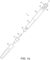
- Fig. 1 is an exploded view of an injection device 1, which may for instance represent Sanofi's Solostar (R) insulin injection pen.
- an injection device 1 which may for instance represent Sanofi's Solostar (R) insulin injection pen.
- the injection device 1 of Fig. 1 is a pre-filled, disposable injection pen that comprises a housing 10 and contains an insulin container 14, to which a needle 15 can be affixed.
- the needle is protected by an inner needle cap 16 and an outer needle cap 17, which in turn can be covered by a cap 18.
- An insulin dose to be ejected from injection device 1 can be selected by turning the dosage knob 12, and the selected dose is then displayed via dosage window 13, for instance in multiples of so-called International Units (IU), wherein one IU is the biological equivalent of about 45.5 micrograms of pure crystalline insulin (1/22 mg).
- An example of a selected dose displayed in dosage window 13 may for instance be 30 IUs, as shown in Fig. 1 . it should be noted that the selected dose may equally well be displayed differently, for instance by means of an electronic display.
- the dosage knob 12 causes a mechanical click sound to provide acoustical feedback to a user.
- the numbers displayed in dosage window 13 are printed on a sleeve that is contained in housing 10 and mechanically interacts with a piston in insulin container 14.
- the insulin dose displayed in display window 13 will be ejected from injection device 1.
- the needle 15 of injection device 1 remains for a certain time in the skin portion after the injection button 11 is pushed, a high percentage of the dose is actually injected into the patient's body. Ejection of the insulin dose also causes a mechanical click sound, which is however different from the sounds produced when using dosage knob 12.
- Injection device 1 may be used for several injection processes until either insulin container 14 is empty or the expiration date of injection device 1 (e.g. 28 days after the first use) is reached.
- injection device 1 before using injection device 1 for the first time, it may be necessary to perform a so-called "prime shot” to remove air from insulin container 14 and needle 15, for instance by selecting two units of insulin and pressing injection button 11 while holding injection device 1 with the needle 15 upwards.
- a so-called "prime shot” to remove air from insulin container 14 and needle 15, for instance by selecting two units of insulin and pressing injection button 11 while holding injection device 1 with the needle 15 upwards.
- the ejected doses substantially correspond to the injected doses, so that, for instance when making a proposal for a dose to be injected next, this dose equals the dose that has to ejected by the injection device. Nevertheless, differences (e.g. losses) between the ejected doses and the injected doses may of course be taken into account.
- Fig. 2a is a schematic illustration of an embodiment of a supplementary device 2 to be releasably attached to injection device 1 of Fig. 1 .
- Supplementary device 2 comprises a housing 20 with a mating unit configured and embrace the housing 10 of injection device 1 of Fig. 1 , so that supplementary device 2 sits tightly on housing 10 of injection device 1, but is nevertheless removable from injection device 1, for instance when injection device 1 is empty and has to be replaced.
- Fig. 2a is highly schematic, and details of the physical arrangement are described below with reference to Figure 2b .
- Supplementary device 2 contains optical and acoustical sensors for gathering information from injection device 1. Information is displayed via display unit 21 of supplementary device 2. The dosage window 13 of injection device 1 is obstructed by supplementary device 2 when attached to injection device 1.
- Supplementary device 2 further comprises three user input transducers, illustrated schematically as a button 22. These input transducers 22 allow a user to turn on/off supplementary device 2, to trigger actions (for instance to cause establishment of a connection to or a pairing with another device, and/or to trigger transmission of information from supplementary device 2 to another device), or to confirm something.
- Fig. 2b is a schematic illustration of a second embodiment of a supplementary device 2 to be releasably attached to injection device 1 of Fig. 1 .
- Supplementary device 2 comprises a housing 20 with a mating unit configured and embrace the housing 10 of injection device 1 of Fig. 1 , so that supplementary device 2 sits tightly on housing 10 of injection device 1, but is nevertheless removable from injection device 1.
- Supplementary device 2 further comprises three user input buttons or switches.
- a first button 22 is a power on/off button, via which the supplementary device 2 may for instance be turned on and off.
- a second button 33 is a communications button.
- a third button 34 is a confirm or OK button.
- the buttons 22, 33, 34 may be any suitable form of mechanical switch. These input buttons 22 allow a user to turn on/off supplementary device 2, to trigger actions (for instance to cause establishment of a connection to or a pairing with another device, and/or to trigger transmission of information from supplementary device 2 to another device), or to confirm something.
- Fig. 2c is a schematic illustration of a third embodiment of a supplementary device 2 to be releasably attached to injection device 1 of Fig. 1 .
- Supplementary device 2 comprises a housing 20 with a mating unit configured and embrace the housing 10 of injection device 1 of Fig. 1 , so that supplementary device 2 sits tightly on housing 10 of injection device 1, but is nevertheless removable from injection device 1.
- the dosage window 13 of injection device 1 is obstructed by supplementary device 2 when attached to injection device 1.
- Supplementary device 2 further comprises a touch-sensitive input transducer 35. It also comprises a single user input button or switch 22.
- the button 22 is a power on/off button, via which the supplementary device 2 may for instance be turned on and off.
- the touch sensitive input transducer 35 can be used to trigger actions (for instance to cause establishment of a connection to or a pairing with another device, and/or to trigger transmission of information from supplementary device 2 to another device), or to confirm something.
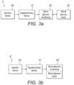
- Figs. 3A and 3b show possible distributions of functions among devices when using a supplementary device (such as the supplementary devices of Fig. 2a and 2b ) together with an injection device.
- a supplementary device such as the supplementary devices of Fig. 2a and 2b
- the supplementary device 41 determines information from injection device 40, and provides this information (e.g. type and/or dose of the medicament to be injected) to a blood glucose monitoring system 42 (e.g. via a wired or wireless connection).
- Blood glucose monitoring system 42 (which may for instance be embodied as desktop computer, personal digital assistant, mobile phone, tablet computer, notebook, netbook or ultrabook) keeps a record of the injections a patient has received so far (based on the ejected doses, for instance by assuming that the ejected doses and the injected doses are the same, or by determining the injected doses based on the ejected doses, for instance be assuming that a pre-defined percentage of the ejected dose is not completely received by the patient). Blood glucose monitoring system 42 may for instance propose a type and/or dose of insulin for the next injection for this patient.
- blood glucose meter 43 may be embodied as a separate device that is configured to receive a small blood probe (for instance on a carrier material) of a patient and to determine the blood glucose level of the patient based on this blood probe.
- Blood glucose meter 43 may however also be a device that is at least temporarily implanted into the patient, for instance in the patient's eye or beneath the skin.
- Fig. 3b is a modified constellation 4' where the blood glucose meter 43 of Fig. 3a has been included into blood glucose monitoring system 42 of Fig. 3a , thus yielding the modified blood glucose monitoring system 42' of Fig. 3b .
- the functionalities of injection device 40 and supplementary device 41 of Fig. 3a are not affected by this modification.
- the functionality of blood glucose monitoring system 42 and blood glucose meter 43 combined into blood glucose monitoring system 42' are basically unchanged, apart from the fact that both are now comprised in the same device, so that external wired or wireless communication between these devices is no longer necessary. However, communication between blood glucose monitoring system 42 and blood glucose meter 43 takes place within system 42'.
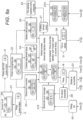
- Fig. 4 shows a schematic view of the supplementary device 2 of Fig. 2a in a state where it is attached to injection device 1 of Fig. 1 .
- a plurality of components are comprised. These are controlled by a processor 24, which may for instance be a microprocessor, a Digital Signal Processor (DSP), Application Specific Integrated Circuit (ASIC), Field Programmable Gate Array (FPGA) or the like.
- Processor 24 executes program code (e.g. software or firmware) stored in a program memory 240, and uses a main memory 241, for instance to store intermediate results.
- Main memory 241 may also be used to store a logbook on performed ejections/injections.
- Program memory 240 may for instance be a Read-Only Memory (ROM), and main memory may for instance be a Random Access Memory (RAM).
- processor 24 interacts with a first button 22, via which supplementary device 2 may for instance be turned on and off.
- a second button 33 is a communications button. The second button may be used to trigger establishment of a connection to another device, or to trigger a transmission of information to another device.
- a third button 34 is a confirm or OK button. The third button 34 can be used to acknowledge information presented to a user of supplementary device 2.
- buttons 33, 34 may be omitted. Instead, one or more capacitive sensors or other touch sensors are provided.
- Display unit 21 is used to display information to a user of supplementary device 2, for instance on present settings of injection device 1, or on a next injection to be given.
- Display unit 21 may also be embodied as a touch-screen display, for instance to receive user input.
- Processor 24 also controls an optical sensor 25, embodied as an Optical Character Recognition (OCR) reader, that is capable of capturing images of the dosage window 13, in which a currently selected dose is displayed (by means of numbers printed on the sleeve 19 contained in injection device 1, which numbers are visible through the dosage window 13).
- OCR reader 25 is further capable of recognizing characters (e.g. numbers) from the captured image and to provide this information to processor 24.
- unit 25 in supplementary device 2 may only be an optical sensor, e.g. a camera, for capturing images and providing information on the captured images to processor 24. Then processor 24 is responsible for performing OCR on the captured images.
- Processor 24 also controls light-sources such as light emitting diodes (LEDs) 29 to illuminate the dosage window 13, in which a currently selected dose is displayed.
- LEDs light emitting diodes
- a diffuser may be used in front of the light-sources, for instance a diffuser made from a piece of acrylic glass.
- the optical sensor may comprise a lens (e.g. an aspheric lens) leading to a magnification (e.g. a magnification of more than 3:1 ).
- Processor 24 further controls a photometer 26, that is configured to determine an optical property of the housing 10 of injection device 1, for example a colour or a shading.
- the optical property may only be present in a specific portion of housing 10, for example a colour or colour coding of sleeve 19 or of an insulin container comprised within injection device 1, which colour or colour coding may for instance be visible through a further window in housing 10 (and/or in sleeve 19).
- Information on this colour is then provided to processor 24, which may then determine the type of injection device 1 or the type of insulin contained in injection device 1 (e.g. SoloStar Lantus with purple colour and SoloStar Apidra with blue colour).
- a camera unit may be used instead of photometer 26, and an image of the housing, sleeve or insulin container may then be provided to processor 24 to determine the colour of the housing, sleeve or insulin container by means of image processing.
- one or more light sources may be provided to improve reading of photometer 26.
- the light source may provide light of a certain wavelength or spectrum to improve colour detection by photometer 26.
- the light source may be arranged in such a way that unwanted reflections, for example by dosage window 13, are avoided or reduced.
- a camera unit instead of or in addition to photometer 26, a camera unit may be deployed to detect a code (for instance a bar code, which may for instance be a one- or two-dimensional bar code) related to the injection device and/or the medicament contained therein.
- This code may for instance be located on the housing 10 or on a medicament container contained in injection device 1, to name but a few examples.
- This code may for instance indicate a type of the injection device and/or the medicament, and/or further properties (for instance
- Processor 24 further controls (and/or receives signals from) an acoustic sensor 27, which is configured to sense sounds produced by injection device 1. Such sounds may for instance occur when a dose is dialled by turning dosage knob 12 and/or when a dose is ejected/injected by pressing injection button 11, and/or when a prime shot is performed. These actions are mechanically similar but nevertheless sound differently (this may also be the case for electronic sounds that indicate these actions). Either the acoustic sensor 27 and/or processor 24 may be configured to differentiate these different sounds, for instance to be able to safely recognize that an injection has taken place (rather than a prime shot only).
- Processor 24 further controls an acoustical signal generator 23, which is configured to produce acoustical signals that may for instance be related to the operating status of injection device 1, for instance as feedback to the user.
- an acoustical signal may be launched by acoustical signal generator 23 as a reminder for the next dose to be injected or as a warning signal, for instance in case of misuse.
- Acoustical signal generator may for instance be embodied as a buzzer or loudspeaker.
- a haptic signal generator (not shown) may be used to provide haptic feedback, for instance by means of vibration.
- Processor 24 controls a wireless unit 28, which is configured to transmit and/or receive information to/from another device in a wireless fashion. Such transmission may for instance be based on radio transmission or optical transmission.
- the wireless unit 28 is a Bluetooth transceiver.
- wireless unit 28 may be substituted or complemented by a wired unit configured to transmit and/or receive information to/from another device in a wire-bound fashion, for instance via a cable or fibre connection.
- the units of the data (values) transferred may be explicitly or implicitly defined. For instance, in case of an insulin dose, always International Units (IU) may be used, or otherwise, the used unit may be transferred explicitly, for instance in coded form.
- IU International Units
- Processor 24 receives an input from a pen detection switch 30, which is operable to detect whether the pen 1 is present, i.e. to detect whether the supplementary device 2 is coupled to the injection device 1.
- a battery 32 powers the processor 24 and other components by way of a power supply 31.
- the supplementary device 2 of Fig. 4 is thus capable of determining information related to a condition and/or use of injection device 1. This information is displayed on the display 21 for use by the user of the device. The information may be either processed by supplementary device 2 itself, or may at least partially be provided to another device (e.g. a blood glucose monitoring system).
- a blood glucose monitoring system e.g. a blood glucose monitoring system
- the processor 24 constitutes a processor arrangement.
- the OCR reader 25 constitutes a dose dialled detector operable to detect a dose of medicament dialled.
- the PCR reader 25 also constitutes a dose delivery determiner for determining that a dose of medicament has been delivered.
- the OCR reader 25 and the processor 24 together constitute a quantity determiner for determining a quantity of medicament that has been delivered.
- the processor 24 provides a function of a clock configured to determine a current time.
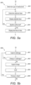
- Figs. 5a-5c are flowcharts of embodiments of methods according to the present invention. These methods may for instance be performed by processor 24 of supplementary device 2 (see Figs. 2b and 4 ), but also by a processor of supplementary device 3 of Fig. 2b , and may for instance be stored in program memory 240 of supplementary device 2, which may for instance take the shape of tangible storage medium 60 of Fig. 6 .
- Fig. 5a shows method steps that are performed in scenarios as shown in Figs. 3a and 3b , where information read by supplementary device 41 from injection device 40 is provided to blood glucose monitoring system 42 or 42' without receiving information back from blood glucose monitoring system 42 or 42'.
- the flowchart 500 starts for instance when the supplementary device is turned on or is otherwise activated.
- a type of medicament for example insulin
- a type of medicament for example insulin
- a code printed on injection device or a component thereof as already described above. Detection of the type of medicament may not be necessary if a patient always takes the same type of medicament and only uses an injection device with this single type of medicament. Furthermore, determination of the type of medicament may be ensured otherwise (e.g. by the key-recess pair shown in Fig. 4 that the supplementary device is only useable with one specific injection device, which may then only provide this single type of medicament).
- a currently selected dose is determined, for instance by OCR of information shown on a dosage window of injection device as described above. This information is then displayed to a user of the injection device in a step 503.
- a prime shot may be differentiated from an actual injection (into a creature) either based on respectively different sounds produced by the injection device and/or based on the ejected dose (e.g. a small dose, for instance less than a pre-defined amount of units, e.g. 4 or 3 units, may be considered to belong to a prime shot, whereas larger doses are considered to belong to an actual injection).
- a small dose for instance less than a pre-defined amount of units, e.g. 4 or 3 units, may be considered to belong to a prime shot, whereas larger doses are considered to belong to an actual injection.
- the determined data i.e. the selected dose and - if applicable - the type of medicament (e.g. insulin)
- the main memory 241 from where it may later be transmitted to another device, for instance a blood glucose monitoring system.
- a differentiation has been made concerning the nature of the ejection for instance if the ejection was performed as a prime shot or as an actual injection, this information may also be stored in the main memory 241, and possibly later transmitted.
- the dose is displayed on the display 21. Also displayed is a time since the last injection which, immediately after injection, is 0 or 1 minute. The time since last dose may be displayed intermittently. For instance, it may be displayed alternately with the name or other identification of the medicament that was injected, e.g. Apidra or Lantus.
- steps 502 and 503 are repeated.
- Fig. 5b shows in more detail exemplary method steps that are performed when the selected dose is determined based on the use of optical sensors only. For instance, these steps may be performed in step 502 of Fig. 5a .
- a sub-image is captured by an optical sensor such as optical sensor 25 of supplementary device 2.
- the captured sub-image is for instance an image of at least a part of the dosage window 13 of injection device 1, in which a currently selected dose is displayed (e.g. by means of numbers and/or a scale printed on the sleeve 19 of injection device 1, which is visible through the dosage window 13).
- the captured sub-image may have a low resolution and/or only show a part of the part of sleeve 19 which is visible through dosage window 13.
- the captured sub- image either shows the numbers or the scale printed on the part of sleeve 19 of injection device 1 which is visible through dosage window 13.
- a step 902 it is determined whether or not there is a change in the captured sub-image.
- the currently captured sub-image may be compared to the previously captured sub-image(s) in order to determine whether or not there is a change.
- the comparison to previously captured sub-images may be limited to the sub-image of the previously captured sub-images that was captured immediately before the current sub-image was captured and/or to the sub-images of the previously captured sub-images that were captured within a specified period of time (e.g. 0.1 seconds) before the current sub-image was captured.
- the comparison may be based on image analysis techniques such as pattern recognition performed on the currently captured sub-image and on the previously captured sub-image.
- Steps 901 and 902 may correspond to a detection of a change in the captured image.
- step 901 is repeated.
- an image is captured by an optical sensor such as optical sensor 25 of supplementary device 2.
- the captured image is for instance an image of the dosage window 13 of injection device 1, in which a currently selected dose is displayed (e.g. by means of numbers and/or a scale printed on the sleeve 19 of injection device 1, which is visible through the dosage window 13).
- the captured image may have a resolution being higher than the resolution of the captured sub-image.
- the captured image at least shows the numbers printed on the sleeve 19 of injection device 1 which are visible through the dosage window 13.
- step 904 optical character recognition (OCR) is performed on the image captured in step 903 in order to recognize the numbers printed on the sleeve 19 of injection device 1 and visible through the dosage window 13, because these numbers correspond to the (currently) selected dose.
- OCR optical character recognition
- the selected dose is determined, for instance by setting a value representing the selected dose to the recognized numbers.
- a step 905 it is determined whether or not there is a change in the determined selected dose and, optionally, whether or not the determined selected dose does not equal zero.
- the currently determined selected dose may be compared to the previously determined selected dose(s) in order to determine whether or not there is a change.
- the comparison to previously determined selected dose(s) may be limited to the previously determined selected dose(s) that were determined within a specified period of time (e.g. 3 seconds) before the current selected dose was determined. If there is no change in the determined selected dose and, optionally, the determined selected dose does not equal zero, the currently determined selected dose is returned/forwarded for further processing (e.g. to processor 24).
- the selected dose is determined if the last turn of the dosage knob 12 is more than 3 seconds ago. If the dosage knob 12 is turned within or after these 3 seconds and the new position remains unchanged for more than 3 seconds, this value is taken as the determined selected dose.
- Fig. 5c shows in more detail method steps that are performed when the selected dose is determined based on the use of acoustical and optical sensors. For instance, these steps may be performed in step 502 of Figs. 5a .
- a sound is captured by an acoustical sensor such as acoustical sensor 27 of supplementary device 2.
- a step 1002 it is determined whether or not the captured sound is a click sound.
- the captured sound may for instance be a click sound that occurs when a dose is dialled by turning dosage knob 12 of injection device 1 and/or when a dose is ejected/injected by pressing injection button 11, and/or when a prime shot is performed. If the captured sound is not a click sound, step 1001 is repeated. Otherwise in a step 1003, an image is captured by an optical sensor such as optical sensor 25 of supplementary device 2. Step 1003 corresponds to step 903 of flowchart 900.
- Step 1004 an OCR is performed on the image captured in step 1003.
- Step 1004 corresponds to step 904 of flowchart 900.
- Step 1005 it is determined whether or not there is a change in the determined selected dose and, optionally, whether or not the determined selected dose does not equal zero. Step 1005 corresponds to step 905 of flowchart 900.
- Fig. 6 is a schematic illustration of a tangible storage medium 60 (a computer program product) that comprises a computer program 61 with program code 62 according to aspects of the present invention.
- This program code may for instance be executed by processors contained in the supplementary device, for instance processor 24 of supplementary device 2 of Figs. 2a and 4 .
- storage medium 60 may represent program memory 240 of supplementary device 2 of Fig. 4 .
- Storage medium 60 may be a fixed memory, or a removable memory, such as for instance a memory stick or card.
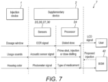
- Fig. 7 is an information sequence chart 7 that illustrates the flow of information between various devices (e.g. the injection device 1 and the supplementary device 2 of Fig. 4 in a scenario as depicted in Figs. 3a or 3b ) according to an embodiment of the present invention.
- a condition and/or use of injection device 1 affects an appearance of its dosage window, sounds generated by injection device 1 and a colour of the housing.
- This information is transformed by sensors 25, 26, 27, 30 of supplementary device 2 into an OCR signal, an acoustic sensor signal and a photometer signal, respectively, which are in turn transformed into information on the dialled dose, on an injection/dialling operation and on the type of insulin by a processor 24 of supplementary device 2, respectively.
- This information is then provided by supplementary device 2 to a blood glucose monitoring system 42. Some or all of this information is displayed to a user via the display 21.
- embodiments of the present invention allow connection of a standard injection device, in particular an insulin device, with a blood glucose monitoring system in a useful and productive way.
- Embodiments of the present invention introduce a supplementary device to allow for this connection, assuming the blood glucose monitoring system has wireless or other communication capabilities.
- the benefits from the connection between the blood glucose monitoring and an insulin injection device are inter alia the reduction of mistakes by the user of the injection device and a reduction of handling steps - no more manual transfer of the injected insulin unit to a blood glucose monitoring is required, in particular to a blood glucose monitoring system with functionality of providing guidance for the next dose based on the last dose injected and latest blood glucose values.
- the user attaches the supplementary device to the pen.
- the supplementary device reads out the injected dose. It may also transfer it to a blood glucose monitoring system with insulin titration capabilities. For patients taking multiple insulins, the supplementary device recognizes the device structure to the insulin type and may also transmit this piece of information to the blood glucose monitoring system.
- the information shown on a display may also converted to a sound signal played to a user through a speaker, for example by a text-to-speech functionality implemented by processor 24 using the acoustical signal generator 23.
- a user with impaired vision may have improved access to the information of supplementary device 2, such as a dialled dose, a recommended dose, a recommended time for administration and/or the like.
- the user inter alia has the following advantages: The user can use the most convenient disposable insulin injector.
- the supplementary device is attachable and detachable (reusable).
- Injected dose information may be transferred to the blood glucose monitoring system automatically (no more transfer mistakes). Improved dose guidance may result from this as the blood glucose monitoring system calculates the dose to be taken.
- patients may also be reminded of injecting their next dose by receiving an alarm signal, for instance, after an appropriate time after a first dose of a medicament (for instance insulin or heparin) has been injected.
- a medicament for instance insulin or heparin
- Injected dose information may be transferred to any computerized system, for instance as input for any dose calculation or any other applicable therapeutic guidance calculation, or for the creation of an alarm signal, for instance to remind the user of taking the next dose.
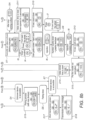
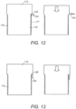
- Figure 8 is a drawing that will now be used to illustrate operation of the supplemental device 2.
- Figure 8 is part flowchart and part state diagram.
- the display 21 is referred to as the LCD 21, so as to avoid confusion between the hardware display 21 and the image that is displayed, and which may be termed a display.
- the LCD 21 may be any suitable form of display hardware.
- the supplemental device is powered off. This provides the display shown in D1.
- D1 also goes to show the general arrangement of the user interface features of the supplemental device.
- an uppermost surface of the supplemental device 2 is shown provided with the LCD 21 and the confirm/OK button 34.
- the confirm/OK button 34 is located to the left of the LCD 21 in this example, although it may have an alternative location in other embodiments.
- the power on/off button 22 and the communications button 33 are located on the side of the supplemental device 2.
- the communications button 34 and the power on/off button 22 are located on the same side of the supplemental device 2, although in other embodiments the buttons are located differently.
- the power on/off button 22 is located on the opposite side of the LCD 21 to the communications button 33.
- the communications button 33 and/or the power on/off button 22 are located on the top surface of the supplemental device 2.
- the input I1 is detected by the supplemental device 2.
- the processor 24 detects that the power on/off button 22 has been pressed for a relatively short period.
- Other user inputs are detected by the supplemental device in a similar manner, and short hand explanation is occasionally provided in the following explanation.
- 'mode' and 'state' are used interchangeably to denote the same thing; if the supplemental device 2 is in mode X it means the same as it being in state X.
- the supplemental device 2 receives a long press of the power on/off button 22, denoted at input I2 in Figure 8 , the supplemental device 2 transitions to the state or display shown at D2.
- a power on progress bar is displayed on the LCD 21.
- This progress bar includes a symbol denoting power or a battery and also includes an indicator relating to the power level of the battery.
- the battery power is approximately one third of the full battery in this example.
- the supplemental device 2 remains in the state indicated by D2 for a predetermined time, for instance 2 or 3 seconds. Following the state indicated in D2, the supplemental device 2 transitions to one of four possible states.
- the supplemental device transitions to the state indicated by D3 in Figure 8 .
- the supplemental device provides on the LCD 21 a graphic indicating that no pen is present. This may be purely graphical, purely textural, or a combination of graphics and text.
- the supplemental device 2 detects that there is not correct alignment between the supplemental device 2 and the injection pen 1, the supplemental device progresses to the state indicated by D4 in Figure 8 .
- An incorrect alignment between the supplemental device 2 and the injection device 1 may be detected by the supplemental device by examination of the symbols received by the OCR module 25 and/or the photometer 26.
- a battery warning graphic is provided. This may take any suitable form.
- the supplemental device 2 does not transition into any of the three states indicated by D3, D4 and D5 in Figure 8 , it transitions to the state indicated by D6. This is called the default state. In the default state, the supplemental device indicates details of the last injection. Put another way, in the default state, the supplemental device 2 displays information relating to the last use of the injection pen 1.
- the default state D6 is also arrived at following the unmounted state indicated by D3, the incorrect alignment state indicated by D4 or the low battery state indicated by D5.
- the supplemental device 2 may remain in any of these preceding states for a predetermined time, for instance 3 seconds, 5 seconds or 10 seconds, before transitioning to the default state, shown in D6.
- the supplemental device 2 may instead refrain from transitioning to the default state indicated by D6 until the supplemental device 2 detects that there is correct alignment between the supplemental device 2 and the injection pen 1.
- the supplemental device may remain in the default state indicated by D6 until the supplemental device detects, by examining the state of the detection switch 30, that the supplemental device 2 is mounted on the injection device 1.
- the supplemental device 2 may remain in the unaligned state until the supplemental device 2 detects correct alignment between the supplemental device 2 and the injection device 1.
- the supplemental device 2 may transition from the unaligned state indicated by D4 to the default state indicated by D6 but refrain from progressing from the default state until the supplemental device 2 detects that there is correct alignment between the supplemental device 2 and the injection device 1.
- the supplemental device 2 indicates periodically that there is a low battery state. This is achieved by a check step E1 that depends from the default state D6.
- the check step E1 involves the supplemental device 2 determining whether the battery 32 is almost empty and, if so, an action step E2 involves providing the warning shown in the display D5 periodically.
- action step E2 involves causing the supplemental device 2 to transition to the low battery state indicated by D5.
- the low battery display indicated by D5 is provided periodically until the battery 32 is replaced or otherwise replenished.
- the low battery display indicated in D5 is provided only when the supplemental device 2 is in the default state. This prevents the low battery warning being provided to the user when the device is in use in connection with delivery of a dose of medicament and/or when the supplemental device 2 is attempting to communicate with another device.
- the supplemental device 2 if when the supplemental device 2 is in the default state, indicated by D6 in the Figure, the supplemental device 2 receives a long press of the power on/off button 22, the supplemental device powers down. Thereafter, the device is in the off state that is indicated by D1 in Figure 8 .
- the supplemental device 2 may be responsive to a long press of the power on/off button 22 to power down from any state.
- the supplemental device 2 may transition from the default state indicated by D6 in response to detecting that the user has turned the dosage dial 12. This is indicated at I3 in the Figure.
- the supplemental device 2 enters a dosage dialling state, which is indicated at D7 in Figure 8 .
- the supplemental device 2 displays on the LCD 21 the dose medicament that is currently dialled into the injection pen 1. This is known by the supplemental device 2 by virtue of reading of the figures 19 from the injection device by the OCR reader 25.
- the supplemental device 2 also displays an indication of the medicament that is present within the injection device 1.
- the medicament is indicated through the display of text that names the medicament, in this case "Apidra".
- the currently set dose is indicated in the dosage dialling state in the display shown in D7 in any suitable way.
- the dose advantageously is indicated in the largest characters that can be accommodated by the LCD 21.
- the height of the letters may be equal to the height of the LCD 21, or at least have a height that is 80 or 90% or more of the height of the LCD 21.
- the supplemental device may provide the display D7 in such a way as to make it clear to the user that the dose value displayed on the LCD 21 relates to a dose that is currently dialled into the injection pen in any suitable way.
- graphical elements provided around the displayed dose value may blink or flash.
- the characters of the dose value themselves may blink or flash.
- the background may blink or flash.
- the supplemental device 2 detects that the dosage dial 12 has not been turned for a predetermined period, for instance 0.5 seconds or 1 second, this is detected at input I3a (although it is actually absence of an input) and the supplemental device 2 transitions to a dose dialled state, which is indicated by the dialled dose display D7a in Figure 8 .
- the supplemental device 2 causes the LCD 21 to provide two different displays, with the device 2 transitioning from one display to the other display and back again on a periodic basis.
- both displays include the dialled dose, and this is provided in the same location.
- the dialled dose may be displayed in the same way in both of the displays.
- One display indicates the medicament that is present in the injection device 1. In this example, this is indicated by text that names the medicament, in this case "Apidra".
- the other display includes an indication that a dose of medicament may be delivered. In this example, this is provided by a graphic of a hand with a confirm/OK button.
- the supplemental device 2 receives an input relating to further turning of the dosage dial 12, indicated by input I3 in Figure 8 , the supplemental device again proceeds to the dosage dialling state that is indicated by D7 in the Figure.
- this input I4 causes transition to an inject now state, which is indicated by D8 in Figure 8 .
- inject now state a graphic is provided indicating to the user that injection is possible.
- the user has two options. They may change the dose. This is achieved by the user selecting the confirm/OK button 34 and then turning the dosage dialler 12. This is detected as an input I5 by the supplemental device. In detecting the input I5, the supplemental device 2 reverts to the dose dialled state indicated by D7 in Figure 8 .
- the user can inject the medicament. This is detected by the supplemental device 2 as an input I6.
- input I6 causes transition to a dosage delivery state, indicated as D9 in Figure 8 .
- the dose remaining dialled into the injection device 1 is displayed on the LCD 21. As the dose is delivered, the dose remaining becomes smaller. As such, the remaining dose value counts down from the dialled in dose towards zero.
- the supplemental device If the user does not deliver the entire dose, this is detected by the supplemental device at input I7 either by detecting depression of the confirm/OK button 34 or by detecting that the user has turned back the dosage dialler 12.
- the input I7 causes transition to a ten second countdown state, indicated at the display D10 in the Figure.
- the supplemental device 2 transitions to a partial dose delivered state, indicated by a display D11 in Figure 8 .
- the supplemental device 2 displays the dose delivered to the user through the injection pen 1.
- the dose delivered is equal to the dose that was dialled in, as detected by the supplemental device when in the dosage dialling state indicated by D7 or the dialled dose state indicated by D7a, minus the dose remaining when the input I7 was detected.
- the medicament that was delivered also is displayed.
- the delivered dose is indicated in characters that are smaller than the characters provided by either of the states indicated by D7 and D7a in Figure 8 .
- Arranged vertically with respect to the delivered dose is an indication of the medicament that was delivered.
- a timer (not shown) within the supplemental device is reset. The timer allows the supplemental device 2 to calculate an elapsed time since a last dose was delivered. Transition from the state indicated by display D11 is to the state indicated by D7 in Figure 8 .
- the supplemental device 2 may exit the dose delivery state indicated by D9 by detecting an input I8 indicative of the injection having been completed. In this case, the supplemental device transitioned to a countdown state that is indicated by the display D12 in Figure 8 .
- the LCD 21 is provided with an icon that is the same as the icon provided in the display of the countdown state indicated by D10 in the Figure.
- the supplemental device 2 transitions to a remove needle instruction state, indicated at the display D13 in Figure 8 .
- the supplemental device 2 provides a graphic that indicates to the user that the needle of the injection device 1 should be replaced.
- the supplemental device 2 transitions to a reset state that is indicated by the display D14 in Figure 8 .
- the value of the delivered dose is stored in the supplemental device 2 and a timer (not shown) is started. The timer provides a value that is indicative of the time elapsed since the last dose.
- the supplemental device 2 transitions to the default state, indicated by D6 in Figure 8 .
- the supplemental device 2 determines whether a device is accessible.
- a device here is for instance the blood glucose measurement unit 42. If a determination at step S3 indicates that a device is accessible and it is determined in E4 that the device is unknown, the supplemental device 2 enters a pairing process state, which is indicated by D15 in the Figure.
- the supplemental device 2 initiates pairing with the detected device.
- the wireless unit 28 being a Bluetooth transceiver
- the pairing process state indicated by D15
- a Bluetooth PIN number is displayed on the LCD 21. This is accompanied with an icon requesting that the user confirm that the PIN number matches with one displayed on the unknown device.
- the supplemental device 2 determines at E5 that pairing has failed, the supplemental device 2 transitions to a Bluetooth error message state, indicated by D16 in the Figure. This state is also transitioned to following input I9 if it is determined at E8 that no device is accessible.
- the Bluetooth error message state indicated by D16
- an icon is displayed on LCD 21 indicating that no communication is possible. Following the Bluetooth error message state, for instance after a predetermined time, the supplemental device 2 transitions to the default state, indicated by D6.
- the supplemental device at E6 determines that pairing has been completed, it transitions to a short transmission state, indicated by D17.
- the supplemental device also transmissions to the short transmission state indicated by D17 from the default state indicated by D6 following input I9 if the supplemental device determines that a device is accessible at E3 and at E7 determines that it is a known device.
- the supplemental device 2 transitions to a transmission done stage, indicated by D18.
- the supplemental device 2 provides a graphic indicating that transmission has been completed.
- the default state indicated by D6.
- operation is as follows.
- the supplemental device 2 is expected to be in the default state for most of the time for which it is powered on.
- the displays D6 when in the default state are the displays that are likely to be seen most by a user of the supplemental device.
- the supplemental device When in the default state, the supplemental device is configured to indicate to the user details of the last delivered dose.
- the details include the quantity of the dose and the time elapsed since the last dose delivery. These details also include the identity of the medicament.
- this is achieved by transitioning between two different displays in the default state.
- the first display is shown uppermost in display D6 in Figure 8 .
- display D6 in Figure 8 .
- a region on the left side occupies approximately two thirds of the area of the display. This region is hereafter termed the last dose region.
- the other region in this example displays a dose that is dialled into the injection pen 1.
- the information displayed on the right side of the LCD 21 is the dialled value from the injection pen 1. This is not influenced by the information displayed on the left side of the LCD 21.
- the last dose region in the first display is divided into two areas. Here, they are upper and lower areas. In a first area, here the lower area, the last delivered dose is displayed. This is in the form of a number, indicating the dose in IUs.
- the elapsed time since the last dose delivered is displayed.
- this is displayed as a time expressed as a number and with a unit of time expressed in Roman characters. Display of the unit of time allows a user to distinguish between the display of the time since the last dose and the quantity of the dose.
- the second area also includes a graphic indicating a timer or clock, which reinforces this message.
- the first area is unchanged.
- the first area thus displays the quantity of the last dose.
- the second area does not show the time elapsed since the last dose. Instead, it shows the medicament of the last dose. Here, this is indicated by text that spells the name of the medicament, in this case "Apidra".
- the clock or timer icon is again displayed in the second area.
- the supplemental device 2 causes the display to transition between the first and second displays, shown uppermost and lowermost respectively, periodically. Transitioning may occur every two seconds, for instance.
- the first area of the dose display region 21B is larger than the second area.
- the height of the characters used to indicate the quantity of the dose are larger than the characters used to indicate the time elapsed since the last dose or the identity of the medicament. As such, a user is able to determine quickly and easily, perhaps with only a glance, the quantity of the last dose.
- the user is able to determine relatively easily the time elapsed since the last dose. It is the time elapsed since the last dose and the quantity of the dose that are the parameters that are most of interest to users of medicaments that are used to treat diabetes. It is these parameters that are most of interest to the user when determining the next dose of medicament, in terms of the time when it should be delivered and in terms of the quantity of medicament that may be needed.
- the provision of the default state and the displays provided in that state by the supplemental device 2 can allow the user better to treat the condition for which the medicament is prescribed.
- the features of the supplemental device when in the default state can allow the user more easily to treat their condition, potentially providing better treatment for the user.
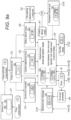
- the supplemental device 2 is provided with a LCD 21 and a power on/off button 22.
- the LCD 21 is a touch-sensitive display, through which a user can provide input to the supplemental device.
- the touch-sensitive LCD 21 also provides the functions provided by the communications button 33 and the confirm/OK button 34 in the embodiment of Figure 8 and Figure 2b .
- the device off state, illustrated by display D1 in Figure 9 is very similar to the corresponding state of the device operation shown in Figure 8 .
- This display D1 illustrates the overall layout provided on the LCD 21.
- a first region 21B of the display is a display region 21B. This is shown on the right of the display of D1 of Figure 9 .
- a second region 21A of the display is an input region 21A. This is shown on the left in D1.
- the input region 21A is also an active display region 21B.
- the input region 21A is a region where user inputs may be received.
- the input region 21A includes a display of a virtual button at appropriate times, in particular when the supplemental device 2 is in certain states.
- the input region 21A in this embodiment is always located in the same place on the LCD 21. This simplifies the experience for the user.
- the input region 21A may change in location depending on the state of the supplemental device.
- the input region 21A is the touch sensitive input 35 shown in Fig.2c .
- the LCD 21 is blank.
- the LCD 21 is blank in a region, nothing is displayed in that region.
- an outline of the virtual button may be displayed, although nothing is displayed within the virtual button.
- the input region 21A is left blank, that is nothing is displayed in the input region 21A.
- the display region 21B is provided with an indicator that indicates the amount of power remaining in the battery 32. This indicator is the same as the indicator shown in D2 of Figure 8 , although it is smaller in size.
- the input region 21A is blank, and a graphic indicating that the pen is not connected is shown in the display region 21B.
- the input region 21A is left blank and the display region 21B indicates that there is not alignment between the supplemental device 2 and the injection device 1.
- the input region 21A is left blank and the display region 21B includes an icon indicating that the battery is almost empty.
- the input region 21A is provided with an icon relating to communication options.
- the input region 21A is provided with an icon indicating a Bluetooth communication option.
- the supplemental device 2 is configured when in the default state to respond to a user input I9 comprising touching of the LCD 21 at the input region 21A to proceed through the checks E3 and E8, as described above with reference to Figure 8 .
- the display region 21B of the display is provided with the displays as described above in relation to the first region of the display in the default state of Figure 8 .
- the check E1 may cause an action E2 which results in transitioning of the device to the battery almost empty state, providing a display shown in D5, periodically.
- the supplemental device 2 may be configured to include a low battery icon within the display region 21B. This is indicated by the display D19 in Figure 9 .
- the currently dialled dose is displayed in the display region 21B.
- the input region 21A is provided with a graphic, which in this case is the word "OK".
- the supplemental device 2 is responsive to detection of a user input at the input region 21A of the LCD 21, represented by input I4 in Figure 9 , to transition to the inject now state, illustrated by display D8 in Figure 9 .
- the input region 21A is provided with an indication of the dialled dose.
- the display region 21B is provided with an icon which is the same as the icon shown in D8 of Figure 8 . After an injection input I8, the number displayed within the input region 21A counts down, reflecting the remaining dialled dose.
- the supplemental device 2 is responsive to detection of a user input at the input region 21A of the LCD 21, indicated by input I7 in Figure 9 , to transition to the countdown state indicated by D10 in the Figure.
- the delivered dose is displayed, along with an indication of the medicament delivered.
- the input region 21A of the LCD 21 is left blank. This is the case also for the remove needle state instruction provided by D13 in Figure 9 . In these states, no transition occurs from user input, so it is appropriate for the input region 21A of the LCD 21 to remain blank.
- the communication error message state, indicated by D16, is similar to the corresponding display of Figure 8 .
- the input region 21A of the LCD 21 includes the text "OK".
- the supplemental device 2 is configured to transition from the communication error message state shown by D16 to the default state shown by D6 after a predetermined time or upon detecting a user input at the input region 21A of the LCD 21.
- the text "OK” is provided at the input region 21A of the LCD 21 also when in the pairing state, indicated by display D15 in Figure 9 .
- the supplemental device 2 is configured to respond to detection of a user input at the input region 21A of the LCD 21 to transition either to the communication error message state shown by D16 or the short transmission state indicated by D17 depending on whether pairing has been achieved. Alternatively, transitioning may occur automatically, for instance in response to detection of a time out.
- the arrangement of the supplemental device 2 of Figure 2c is such that the user cannot operate the communications button other than when the device is in the default state, indicated by D6. This prevents the user believing that the supplemental device 2 might lead to actuation of the communications button 33 other than when in the default state, shown by D6.
- the communication states etc may be replaced by alternative states in which operation of the supplemental device 2 is quite different, or these states may be omitted altogether.
- Figure 10 shows a lateral cross-section taken through the injection device 1 with supplemental device 2 attached.
- Figure 10 only the central part of the supplemental device 2 is shown; the mating unit which embraces the injection device 1 is omitted for clarity.
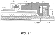
- Figure 11 shows an axial cross-section taken through the injection device 1 with supplemental device 2 attached. Some components of the supplemental device are omitted or shown in wireframe in Figure 11 for clarity.
- FIGs 10 and 11 both show an electromechanical switch arrangement 110.
- the electromechanical switch arrangement 110 comprises a self-contained unit which is fitted to the supplemental device 2.
- the electromechanical switch arrangement 110 may for example be housed in a recess in the underside of the supplemental device 2 (the part which contacts the injection device 1).
- the electromechanical switch arrangement 110 may be secured to the supplemental device 2 by friction or by an interlocking arrangement (not shown), or alternatively by screws, adhesive or the like.
- the electromechanical switch arrangement 110 comprises a main body 111 (also referred to herein as a housing 111). A cavity is defined inside the main body 111. An upper part of the main body 111 is arranged to engage with the housing 20 of the supplemental device 2 to secure the electromechanical switch arrangement 110 to the supplemental device 2. A lower part of the main body is concave in shape and matches the curvature of the injection device 1. The lower part of the main body 111 has an aperture.
- the injection device 1 to which the supplemental device 2 is to be attached has a corrugated dialling sleeve 119.
- the corrugations are defined by troughs 116 and crests 117.
- the dialling sleeve 119 is configured to rotate with the dosage knob 12 during dose dialling.
- the dialling sleeve 119 may be coupled directly to the injection button 11.
- the lower part of the main body 111 of the electromechanical switch arrangement 110 abuts several of the crests 117 of the corrugated dialling sleeve 119 but the dialling sleeve 119 is free to rotate relative to the electromechanical switch arrangement 110.
- a switch 113 (also referred to as a protrusion 113, a switching member 113 or switching lever 113) is rotatably mounted inside the main body 111 of the electromechanical switch arrangement 110.
- the switch 113 has a protrusion 118 and is arranged such that this protrusion passes through the aperture in the main body 111 and protrudes from the main body 111.
- An internal spring 114 biases the switch 113 towards the position shown in Figure 10 , in which the switch 113 abuts an internal surface of the main body 111 and the end of the protrusion 118 abuts a trough 116 of the dialling sleeve 119.
- the internal spring 114 may for example be a torsion spring.
- the injection device 1 is configured such that a small portion of the dialling sleeve 119 adjacent the dosage button 12 extends out of the housing 10 of the injection device 1 when no dose has been dialled. This allows the protrusion 118 to contact the dialling sleeve 119 at all times during operation of the device.
- the inner wall of the electromechanical switch arrangement 110 comprises two electrical contacts 112. These contacts are arranged to be engaged by corresponding electrical contacts on the switch 113.
- the contacts 112 and/or the corresponding contacts on the switching member 113 are sprung contacts.
- a first of the contacts 112 may be engaged at all times by a contact on the switch.
- a second of the contacts 112 is not engaged by the switch 113 when in the position shown in Figure 10 .
- This second contact 112 is engaged by the switch 113 only when the protrusion 118 of the switch 113 rides up a crest 117 of the dialling sleeve 119, causing the switch to rotate within the main body 111.
- the supplemental device 2 comprises a processor 24.
- This processor 24 is configured to control the application of a signal to one of the contacts 112 and to detect when the circuit is completed by measuring a signal at the other of the contacts 112.
- the supplemental device 2 may also comprise a compensation spring 115 (also referred to herein as a biasing member), visible in Figure 11 .
- the compensation spring 115 forms part of the supplemental device 2, but is external to the electromechanical switch arrangement 110.
- the compensation spring 115 may be a torsion spring.
- the compensation spring 115 has a first end 120 which is secured internally to the housing 20 of the supplemental device 2.
- the concave underside of the supplemental device 2 is shown in wireframe in Figure 11 .
- the compensation spring 115 has a second end 121 which is secured to the electromechanical switch arrangement 110.
- the second end 121 of the compensation spring 115 may be secured to an upper part of the electromechanical switch arrangement 110 (relative to the orientation of shown in Figure 11 ).
- the compensation spring 115 exerts a force on the electromechanical switch arrangement in the direction of the arrow "A" on Figure 11 . This force causes the electromechanical switch arrangement 110 to be biased towards the injection device 1 and in particular towards the dose dialling sleeve 119.
- the compensation spring 115 may compensate for relative movement between the supplemental device 2 and injection device 1 and/or between the electromechanical switch arrangement 110 and supplemental device 2 as described in greater detail below. These relative movements may be due to manufacturing tolerances of the supplemental device 2, electromechanical switch arrangement 110 and injection device 1, in particular the dose dialling sleeve 119, or may be an intentional design feature. In some other embodiments, the compensation spring 115 is not present.
- the electromechanical switch arrangement 110 is secured to the supplemental device 2. This may be done during manufacture of the supplemental device 2. Alternatively, the electromechanical switch arrangement 110 may be an integral part of the supplemental device 2. A user then fits the supplemental device 2 to the injection device 1 as previously described. Once the supplemental device 2 has been fitted to the injection device 1, the lower part of the electromechanical switch arrangement 110 abuts the surface of the injection device 1.
- the electromechanical switch arrangement 110 When a dose has been dialled into the injection device 1, the electromechanical switch arrangement 110 abuts the dose dialling sleeve 119, as depicted in Figures 10 and 11 .
- the concave underside of the electromechanical switch arrangement 110 contacts several crests 117 of the corrugated surface of the dialling sleeve 119.
- the dose dialling sleeve 119 has a smaller diameter than the outer housing 10 of the injection device 1 and may have the same or a smaller diameter than the dosage knob 12.
- the protrusion 118 of the switching member 113 is forced to protrude through the aperture in the main body 111 of the electromechanical switch arrangement 110.
- the protrusion 118 may contact a trough 116 of the dose dialling sleeve 119 while the electromechanical switch arrangement 110 rests on the crests 117 of the sleeve.
- the dose dialling sleeve 119 rotates relative to the supplemental device 2.
- the protrusion 18 of the switching member 113 follows the contours of the dialling sleeve surface.
- the protrusion 118 rides up the crest, forcing the switching member 113 to rotate within the main body 111.
- the switching member 113 contacts the second of the contacts 112 when the protrusion 118 reaches the top of a crest 117.
- the switching member 113 may be in contact with the first of the contacts 112 at all times.
- An electrical path is formed between the two contacts 112 when the switching member 113 engages with the second of the contacts 112.
- the processor 24 detects that the switch has been closed by applying a signal at the first contact and measuring a signal at the second contact.
- the processor 24 determines from this sequence that one unit (IU) has been dialled into the injection device 1. For each unit which is dialled into the injection device 1, the processor detects one connection of the circuit preceded and followed by a disconnection.
- the switching point of the electromechanical switch arrangement 110 i.e. the point at which the switch 113 completes a circuit between the two contacts 112, occurs when the protrusion 118 rides up to the top of a crest 117.
- the contacts 112 may be sprung contacts to allow some range in the switching point.
- the user then delivers the selected dose.
- the dose dialling sleeve 119 moves back into the injection device 1, but does not rotate.
- the dose dialling sleeve 119 is disconnected from the sleeve 19 and dosage knob 12 by an internal clutch coupled to the injection button 11.
- the dose dialling sleeve 119 may be coupled directly to the injection button, which is itself disconnected from the sleeve 19 and dosage knob 12 by the internal clutch.
- the protrusion 118 of the switching member 113 remains in the same trough 116 of the dose dialling sleeve 119 and no circuit connection is made by the switching member 113.
- the electromechanical switch arrangement 110 may be provided in addition to the OCR reader 25, although the OCR reader is an optional feature. If the processor 24, using the OCR reader 25, detects that the numbers on the sleeve 19 are changing, it may be necessary also to determine whether a dose is being dialled in (dose setting), dialled out (dose correction) or delivered (dose dispense). This determination is not possible using the OCR reader 25 alone. Use of the electromechanical switch arrangement 110 allows this determination to be made.
- the processor 24 determines that the numbers detected by the OCR reader 25 are increasing and also that the electromechanical switch arrangement 110 is being alternately opened and closed, it can be deduced that a dose is being dialled into the injection device 1. If the processor 24 determines that the numbers detected by the OCR reader 25 are decreasing and also that the electromechanical switch arrangement 110 is being alternately opened and closed, it can be deduced that a dose is being dialled out of the injection device 1, without being delivered. If the processor 24 determines that the numbers detected by the OCR reader 25 are decreasing and also that no connection is made in the electromechanical switch arrangement 110, it can be deduced that a dose is being delivered.
- the switching member 113 is described above as rotationally mounted. However, it may instead move in another way within the electromechanical switch arrangement 110, for example by sliding vertically.
- the internal spring 114 may be disposed in the centre of the switching member to bias it towards the aperture in the main body 111.
- the compensation spring 115 may alternatively be a coil spring or another type of biasing means. Instead of being located adjacent to the electromechanical switch arrangement 110, the compensation spring 115 may be located above the electromechanical switch arrangement 110, for example in a cavity between the housing 20 of the supplemental device 2 and the main body 111 of the electromechanical switch arrangement 110.
- the switch 110 is described as being closed when the protrusion 118 ascends a crest of the corrugated dialling sleeve 119 or when the protrusion ascends the axial ramp 122 and open at all other times. However, the switch 110 may alternatively be opened when the protrusion ascends a corrugation or the axial ramp 122 and closed at all other times. Thus the processor may detect either state (or sense) change in the switch 110 and interpret this change as described above.
- the electromechanical switch arrangement 110 may be used to determine that a dose has been completely delivered, i.e. as a "dispense-end switch".
- each trough 116 of the dose dialling sleeve 119 ends at the dosage knob 12 end with an axial ramp 122.
- the switching member 113 remains in a trough 116 of the dose dialling sleeve 119 such that the state of the electromechanical switch arrangement 110 does not change.
- the switching member 113 ascends this axial ramp 122.
- the electromechanical switch arrangement 110 has a different state to when the switching member is in a trough 116 of the dose dialling sleeve 119.
- the electromechanical switch arrangement 110 in all integer unit dose positions the electromechanical switch arrangement 110 has a first state (e.g. an open state), but when in a zero dose position the electromechanical switch arrangement 110 has a second state (e.g. a closed state).
- the processor 24 may then control the supplemental device 2 to enter a "dispense-end" mode and control the display 21 to show an appropriate screen.
- the processor 24 may determine that a dose dispense has been completed.
- the processor 24 may place the supplemental device 2 into a power conserving "sleep mode" after this (or a longer) predetermined time.
- the supplemental device 2 may be woken from a sleep mode when a new dose is dialled into the injection device 1 and the state of the electromechanical switch arrangement 110 changes.
- the same switching member 113 which contacts the crests 117 and troughs 116 of the dose dialling sleeve 119 is also used to determine when the dose dialling sleeve 119 reaches a zero unit dose position.
- An advantage of these embodiments is that detection of a completed dose can be accomplished without modification to the existing electromechanical switch arrangement 110. If the detection of a completed dose is used as a trigger to place the supplemental device 2 into a sleep mode, then the overall power consumption of the device is reduced. This may be particularly beneficial when the supplemental device 2 contains power heavy components, such as an OCR system.
- Figure 12 shows schematically another embodiment of the invention in which another switching member 124, being part of a second electromechanical switch (not shown), is used as the "dispense-end" detection switch.
- the first switching member 113 is used as previously described to contact the dose dialling sleeve 119 at all times during rotation and is omitted from Figure 12 .
- the second electromechanical switch (not shown) may be housed within the electromechanical switch arrangement 110 or alternatively may be part of a second electromechanical switch arrangement.
- the second switching member 124 protrudes from the underside of the supplemental device 2, but is not biased against the surface of the dose dialling sleeve 119. It does not therefore move into the troughs 116 of the dose dialling sleeve.
- the switching member 124 may contact the crests 117 of the dose dialling sleeve 119 as the dialling sleeve is rotated, but this contact does not cause the second switch to change state.
- the second switching member 124 may contact the dose dialling sleeve 119 at a different circumferential position to the first switching member 113 and/or be offset axially with respect to the first switching member 113.
- Figure 12 shows two positions of the second switching member 124 relative to the dose dialling sleeve 119.
- the first position represents the arrangement when a dose of one unit is dialled into the supplemental device 2.
- the second electromechanical switch arrangement has a first state (e.g an open state).
- the last unit dose is delivered (indicated by the arrow in Figure 12 )
- the second switching member 124 ascends the axial ramp 122 and the state of the second electromechanical switch arrangement changes to a second state (e.g. a closed state) as shown in the second position in Figure 12 .
- the change in state of the second switch only occurs when the dialled dose is decreased from one to zero.
- the processor 24 may detect the change in state of the second switch and determine that a dose of zero units is dialled into the device.
- the first switching member 113 may also ascend the ramp 122 or may be positioned such that it does not ascend the ramp 122.
- the second switch acts as a reliable means of determining when a dose has been fully delivered. Detection that a dose has been fully delivered may be used to activate a power saving or sleep mode as previously described or to trigger another function of the supplemental device 2, such as displaying the dose that has been delivered on the display 21 of the supplemental device 2 and/or triggering communication of data stored in the supplemental device 2 with an external apparatus.
- Figure 13 shows schematically a further embodiment of the invention in which another switching member 126, being part of a second electromechanical switch (not shown), is used as the "dispense-end" detection switch.
- the first switching member 113 is again omitted from Figure 13 .
- the embodiment shown in Figure 13 is similar to that shown in Figure 12 except that the switching member 126 is movable in an axial direction, rather than in a radial direction.
- the internal construction of the second electromechanical switch may be modified to accommodate this axial movement.
- the switching member 126 may contact a cam or be connected to a rotatable or hinged arm or actuator within the switch arrangement in order to cause the state of the switch to change.
- the switching member 126 does not contact the troughs 116 or crests 117 of the dose dialling sleeve 119. Alternatively, the switching member 126 may slide across the crests 117 of the dose dialling sleeve 119. The switching member 126 is contacted by the dose dialling sleeve 119 and moved only when the dose dialling sleeve 119 moves from a one unit dose position to a zero unit dose position. In the embodiment of Figure 13 , the dose dialling sleeve 119 does not require an axial ramp, but could instead comprise a flange 128.
- a surface of the dosage knob 112 where it meets the dose dialling sleeve 119 may act as the flange 128 or alternatively the flange may comprise a separate ring of material having a larger diameter than the dose dialling sleeve 119.
- Figure 13 shows two positions of the switching member 126 relative to the dose dialling sleeve 119.
- the first position represents the arrangement when a dose of one unit is dialled into the supplemental device 2.
- the second electromechanical switch arrangement has a first state (e.g an open state).
- the flange 128 abuts the switching member 126 causing it to move as shown in the second position in Figure 13 .
- the state of the second electromechanical switch arrangement changes to a second state (e.g. a closed state).
- the change in state of the second switch only occurs when the dialled dose is decreased from one to zero.
- the processor 24 may detect the change in state of the second switch and determine that a dose of zero units is dialled into the device.
- the second switch acts as a reliable means of determining when a dose has been fully delivered. Detection that a dose has been fully delivered may be used to activate a power saving or sleep mode as previously described or to trigger another function of the supplemental device 2, such as displaying the dose that has been delivered on the display 21 of the supplemental device 2 and/or triggering communication of data stored in the supplemental device 2 with an external apparatus.
Claims (12)
- Ergänzungsvorrichtung (2) zum Anbringen an einer Injektionsvorrichtung (1), die einen Dosiseinstellmechanismus hat, der eine drehbare Wählhülse (119) aufweist, wobei die Ergänzungsvorrichtung Folgendes aufweist:eine elektromechanische Schalteranordnung (110) mit einem offenen Zustand und einem geschlossenen Zustand, wobei die elektromechanische Schalteranordnung einen Vorsprung (118) aufweist, der dazu ausgestaltet ist, von einem Hauptkörper der elektromechanischen Schalteranordnung vorzuragen, um eine Oberfläche der Injektionsvorrichtung zu kontaktieren, wenn eine Dosis von null Einheiten in die Injektionsvorrichtung gewählt wird, wobei der Zustand der elektromagnetischen Schalteranordnung dazu ausgestaltet ist, sich zu ändern, wenn eine in die angebrachte Injektionsvorrichtung gewählte Dosis von einer Einheit auf null Einheiten verringert wird, undeine Prozessoranordnung (24), die dazu ausgestaltet ist:dadurch gekennzeichnet, dass die Ergänzungsvorrichtung als Reaktion auf das Bestimmen aus der einen oder den mehreren Zustandsänderungen, dass die in die Injektionsvorrichtung gewählte Dosis von einer Einheit auf null Einheiten verringert worden ist, in einen Energiesparmodus versetzt wird.
eine oder mehrere Änderungen in dem Zustand der elektromechanischen Schalteranordnung zu erfassen, aus der einen oder den mehreren Zustandsänderungen zu bestimmen, dass die in die Injektionsvorrichtung gewählte Dosis von einer Einheit auf null Einheiten verringert worden ist; und - Ergänzungsvorrichtung nach Anspruch 1, wobei der Vorsprung ferner dazu ausgestaltet ist, die Oberfläche der Injektionsvorrichtung zu kontaktieren, wenn eine beliebige Anzahl von Dosiseinheiten in die Injektionsvorrichtung gewählt ist.
- Ergänzungsvorrichtung nach Anspruch 1, wobei der Vorsprung ferner dazu ausgestaltet ist, die Oberfläche der Injektionsvorrichtung nur dann zu kontaktieren, wenn eine Dosis von null Einheiten in die Injektionsvorrichtung gewählt ist.
- Ergänzungsvorrichtung nach Anspruch 1, wobei die Ergänzungsvorrichtung Folgendes aufweist:eine erste elektromechanische Schalteranordnung (110) mit einem offenen Zustand und einem geschlossenen Zustand, wobei die erste elektromechanische Schalteranordnung einen ersten Vorsprung (118) aufweist, der dazu ausgestaltet ist, von einem Hauptkörper des elektromechanischen Schalters vorzuragen, um die Oberfläche der Injektionsvorrichtung zu kontaktieren, wenn eine beliebige Anzahl von Dosiseinheiten in die Injektionsvorrichtung gewählt ist, undeine zweite elektromechanische Schalteranordnung mit einem offenen Zustand und einem geschlossenen Zustand, wobei die zweite elektromechanische Schalteranordnung einen zweiten Vorsprung (124) aufweist, der dazu ausgestaltet ist, von einem Hauptkörper des elektromechanischen Schalters vorzuragen, um die Oberfläche der Injektionsvorrichtung nur dann zu kontaktieren, wenn eine Dosis von null Einheiten in die Injektionsvorrichtung gewählt ist.
- Ergänzungsvorrichtung nach Anspruch 4, wobei die Prozessoranordnung dazu ausgestaltet ist, zu bestimmen, ob jede der ersten und zweiten elektromechanischen Schalteranordnungen offen oder geschlossen ist.
- Ergänzungsvorrichtung nach Anspruch 4 oder Anspruch 5, wobei die Prozessoranordnung dazu ausgestaltet ist, ein Rotationsausmaß der Oberfläche der Injektionsvorrichtung aus von der ersten elektromechanischen Schalteranordnung empfangenen Signalen zu bestimmen.
- Ergänzungsvorrichtung nach einem der vorhergehenden Ansprüche, wobei die Ergänzungsvorrichtung ferner einen Gewählte-Dosis-Detektor (25) aufweist, der dahingehend betätigbar ist, eine in die angebrachte Injektionsvorrichtung gewählte Medikamentendosis zu erfassen.
- Ergänzungsvorrichtung nach Anspruch 7, wobei der Gewählte-Dosis-Detektor eine Bilderfassungsvorrichtung und ein optisches Zeichenerkennungssystem aufweist.
- System, das eine Ergänzungsvorrichtung nach einem der vorhergehenden Ansprüche und eine Injektionsvorrichtung aufweist.
- System nach Anspruch 9, wobei die Injektionsvorrichtung Folgendes aufweist:ein Gehäuse (10),eine gewellte Wählhülse (119), die drehbar in dem Gehäuse gelagert ist, wobei die gewellte Wählhülse eine Vielzahl von axial ausgerichteten Wellungen hat, undeinen drehbaren Dosierungsknopf (12), der an einem ersten Ende der gewellten Wählhülse an die gewellte Wählhülse gekoppelt ist, wobei der Vorsprung der elektromechanischen Schalteranordnung dazu ausgestaltet ist, die gewellte Wählhülse in Eingriff zu nehmen.
- System nach Anspruch 10, wobei jedes einer Vielzahl von Tälern (116), die die Wellungen bilden, an dem ersten Ende der gewellten Wählhülse mit einer Neigung endet.
- System nach Anspruch 10, wobei der drehbare Dosierungsknopf einen größeren Durchmesser als die gewellte Wählhülse hat und an dem ersten Ende der gewellten Wählhülse einen Flansch definiert.
Applications Claiming Priority (3)
| Application Number | Priority Date | Filing Date | Title |
|---|---|---|---|
| EP13166724 | 2013-05-07 | ||
| EP14724041.0A EP2994180B1 (de) | 2013-05-07 | 2014-05-02 | Ergaenzungsvorrichtung fuer die befestigung an einer injektionsvorrichtung |
| PCT/EP2014/058970 WO2014180745A1 (en) | 2013-05-07 | 2014-05-02 | Supplemental device for attachment to an injection device |
Related Parent Applications (2)
| Application Number | Title | Priority Date | Filing Date |
|---|---|---|---|
| EP14724041.0A Division EP2994180B1 (de) | 2013-05-07 | 2014-05-02 | Ergaenzungsvorrichtung fuer die befestigung an einer injektionsvorrichtung |
| EP14724041.0A Division-Into EP2994180B1 (de) | 2013-05-07 | 2014-05-02 | Ergaenzungsvorrichtung fuer die befestigung an einer injektionsvorrichtung |
Publications (2)
| Publication Number | Publication Date |
|---|---|
| EP3593843A1 EP3593843A1 (de) | 2020-01-15 |
| EP3593843B1 true EP3593843B1 (de) | 2023-09-27 |
Family
ID=48463709
Family Applications (2)
| Application Number | Title | Priority Date | Filing Date |
|---|---|---|---|
| EP14724041.0A Active EP2994180B1 (de) | 2013-05-07 | 2014-05-02 | Ergaenzungsvorrichtung fuer die befestigung an einer injektionsvorrichtung |
| EP19189194.4A Active EP3593843B1 (de) | 2013-05-07 | 2014-05-02 | Add-on modul mit mechanischem dosis schalter |
Family Applications Before (1)
| Application Number | Title | Priority Date | Filing Date |
|---|---|---|---|
| EP14724041.0A Active EP2994180B1 (de) | 2013-05-07 | 2014-05-02 | Ergaenzungsvorrichtung fuer die befestigung an einer injektionsvorrichtung |
Country Status (7)
| Country | Link |
|---|---|
| US (2) | US10744269B2 (de) |
| EP (2) | EP2994180B1 (de) |
| JP (2) | JP6510495B2 (de) |
| CN (1) | CN105324142B (de) |
| DK (2) | DK3593843T3 (de) |
| HK (1) | HK1215403A1 (de) |
| WO (1) | WO2014180745A1 (de) |
Families Citing this family (27)
| Publication number | Priority date | Publication date | Assignee | Title |
|---|---|---|---|---|
| EP3871713A1 (de) | 2011-03-24 | 2021-09-01 | Sanofi-Aventis Deutschland GmbH | Vorrichtung und verfahren zur erkennung einer mit einer medizinischen vorrichtung durchführbaren betätigungsaktion |
| WO2014180745A1 (en) * | 2013-05-07 | 2014-11-13 | Sanofi-Aventis Deutschland Gmbh | Supplemental device for attachment to an injection device |
| KR20170097020A (ko) | 2014-12-23 | 2017-08-25 | 오토메드 피티와이 리미티드 | 딜리버리 장치, 시스템 및 관련 방법 |
| EP3058970A1 (de) * | 2015-02-19 | 2016-08-24 | Sanofi-Aventis Deutschland GmbH | Datensammlungsvorrichtung zur Befestigung an einer Injektionsvorrichtung |
| EP3132821B1 (de) * | 2015-03-03 | 2018-12-19 | Innovative Precision Instruments Limited | Vorrichtung zur erkennung der arzneimittelinformation und injektionsvorrichtung zur erkennung des arzneimittelinformationstyps |
| EP4316552A3 (de) | 2015-06-09 | 2024-04-17 | Sanofi-Aventis Deutschland GmbH | Datensammelvorrichtung zur befestigung an einer injektionsvorrichtung |
| US11197957B2 (en) | 2015-07-13 | 2021-12-14 | Novo Nordisk A/S | Drug delivery device with end-of-dose trigger arrangement |
| US10864327B2 (en) | 2016-01-29 | 2020-12-15 | Companion Medical, Inc. | Automatic medication delivery tracking |
| HRP20220838T1 (hr) | 2016-07-15 | 2022-10-14 | Eli Lilly And Company | Modul za detekciju doze za uređaj za davanje lijeka |
| DK3509669T3 (da) | 2016-09-09 | 2021-05-31 | Sanofi Aventis Deutschland | Dataindsamlingsapparat til fastgørelse på en injektionsanordning |
| EP3595742B1 (de) * | 2017-03-15 | 2021-08-25 | Novo Nordisk A/S | Zubehörvorrichtung mit sekundärem bildanalysemerkmal |
| WO2019001919A1 (en) * | 2017-06-27 | 2019-01-03 | Novo Nordisk A/S | ACCESSORY DEVICE HAVING A MATCHING ELEMENT |
| EP3668568A1 (de) | 2017-08-18 | 2020-06-24 | Eli Lilly and Company | Dosismessmodul auf einem injektionspen |
| JP6932836B2 (ja) | 2017-08-21 | 2021-09-08 | イーライ リリー アンド カンパニー | 薬物送達装置のための用量検出モジュール |
| AU2018319545B2 (en) | 2017-08-21 | 2021-02-25 | Eli Lilly And Company | Dose detection module for a medication delivery device |
| EP4104884A1 (de) | 2017-08-21 | 2022-12-21 | Eli Lilly and Company | Medikamentenabgabevorrichtung mit erfassungssystem |
| US10987464B2 (en) | 2017-12-12 | 2021-04-27 | Bigfoot Biomedical, Inc. | Pen cap for insulin injection pens and associated methods and systems |
| EP3724891A1 (de) | 2017-12-12 | 2020-10-21 | Bigfoot Biomedical, Inc. | Medizininjektions- und krankheitsmanagementsysteme, -vorrichtungen und -verfahren |
| US11077243B2 (en) | 2017-12-12 | 2021-08-03 | Bigfoot Biomedical, Inc. | Devices, systems, and methods for estimating active medication from injections |
| US11116899B2 (en) | 2017-12-12 | 2021-09-14 | Bigfoot Biomedical, Inc. | User interface for diabetes management systems and devices |
| US11464459B2 (en) | 2017-12-12 | 2022-10-11 | Bigfoot Biomedical, Inc. | User interface for diabetes management systems including flash glucose monitor |
| EP3731904A1 (de) * | 2017-12-28 | 2020-11-04 | Sanofi | Sensorvorrichtung zur befestigung an einer injektionsvorrichtung |
| CN112135649B (zh) | 2018-05-18 | 2023-01-31 | 诺和诺德股份有限公司 | 具有标识符确定的传感器组件 |
| EP3572107A1 (de) * | 2018-05-22 | 2019-11-27 | Tecpharma Licensing AG | Klick-ereignis-identifikation in ausgabevorrichtungen |
| US11948671B2 (en) | 2019-04-11 | 2024-04-02 | Medtronic Minimed, Inc. | Intelligent accessories for medicine dispensing device |
| US20230108921A1 (en) * | 2019-10-28 | 2023-04-06 | Sanofi | Electronic Label for a Drug Delivery Device |
| CN115003238A (zh) * | 2019-11-27 | 2022-09-02 | 帕西拉冷冻技术股份有限公司 | 用于低温设备的显示设备和界面 |
Family Cites Families (38)
| Publication number | Priority date | Publication date | Assignee | Title |
|---|---|---|---|---|
| US533575A (en) | 1895-02-05 | wilkens | ||
| US5226895A (en) | 1989-06-05 | 1993-07-13 | Eli Lilly And Company | Multiple dose injection pen |
| GB9007113D0 (en) | 1990-03-29 | 1990-05-30 | Sams Bernard | Dispensing device |
| DK0525525T3 (da) * | 1991-07-24 | 1995-10-02 | Medico Dev Investment Co | Injektor |
| DK175491D0 (da) | 1991-10-18 | 1991-10-18 | Novo Nordisk As | Apparat |
| US5279586A (en) | 1992-02-04 | 1994-01-18 | Becton, Dickinson And Company | Reusable medication delivery pen |
| CH682805A5 (de) * | 1992-02-24 | 1993-11-30 | Medimpex Ets | Anzeigeeinrichtung für ein Injektionsgerät. |
| US5320609A (en) | 1992-12-07 | 1994-06-14 | Habley Medical Technology Corporation | Automatic pharmaceutical dispensing syringe |
| US5383865A (en) * | 1993-03-15 | 1995-01-24 | Eli Lilly And Company | Medication dispensing device |
| ZA941881B (en) | 1993-04-02 | 1995-09-18 | Lilly Co Eli | Manifold medication injection apparatus and method |
| US5582598A (en) | 1994-09-19 | 1996-12-10 | Becton Dickinson And Company | Medication delivery pen with variable increment dose scale |
| WO1996027400A1 (en) | 1995-03-07 | 1996-09-12 | Eli Lilly And Company | Recyclable medication dispensing device |
| US5688251A (en) | 1995-09-19 | 1997-11-18 | Becton Dickinson And Company | Cartridge loading and priming mechanism for a pen injector |
| US5674204A (en) | 1995-09-19 | 1997-10-07 | Becton Dickinson And Company | Medication delivery pen cap actuated dose delivery clutch |
| DE19730999C1 (de) | 1997-07-18 | 1998-12-10 | Disetronic Licensing Ag | Dosierknopfsicherung an einer Vorrichtung zur dosierten Verabreichung eines injizierbaren Produkts |
| US5921966A (en) | 1997-08-11 | 1999-07-13 | Becton Dickinson And Company | Medication delivery pen having an improved clutch assembly |
| UA56256C2 (uk) | 1998-01-30 | 2003-05-15 | Ново Нордіск А/С | Шприц для ін'єкцій |
| US6221053B1 (en) | 1998-02-20 | 2001-04-24 | Becton, Dickinson And Company | Multi-featured medication delivery pen |
| US5961495A (en) | 1998-02-20 | 1999-10-05 | Becton, Dickinson And Company | Medication delivery pen having a priming mechanism |
| US6248095B1 (en) | 1998-02-23 | 2001-06-19 | Becton, Dickinson And Company | Low-cost medication delivery pen |
| AU6892100A (en) | 1999-08-05 | 2001-03-05 | Becton Dickinson & Company | Medication delivery pen |
| GB0007071D0 (en) | 2000-03-24 | 2000-05-17 | Sams Bernard | One-way clutch mechanisms and injector devices |
| US6663602B2 (en) | 2000-06-16 | 2003-12-16 | Novo Nordisk A/S | Injection device |
| US6899699B2 (en) | 2001-01-05 | 2005-05-31 | Novo Nordisk A/S | Automatic injection device with reset feature |
| EP1392377B1 (de) | 2001-05-16 | 2007-02-28 | Eli Lilly And Company | Arzneimitteleinspritzvorrichtung mit rückstellung erleichternder antriebsanordnung |
| GB0304823D0 (en) | 2003-03-03 | 2003-04-09 | Dca Internat Ltd | Improvements in and relating to a pen-type injector |
| DE102004063647A1 (de) | 2004-12-31 | 2006-07-20 | Tecpharma Licensing Ag | Vorrichtung zur dosierten Verabreichung eines fluiden Produkts mit Kupplung |
| DK2073871T3 (da) * | 2006-09-29 | 2013-06-10 | Novo Nordisk As | Injektionsanordning med elektroniske detekteringsmidler |
| US9108006B2 (en) | 2007-08-17 | 2015-08-18 | Novo Nordisk A/S | Medical device with value sensor |
| US8647309B2 (en) | 2008-05-02 | 2014-02-11 | Sanofi-Aventis Deutschland Gmbh | Medication delivery device |
| ES2673294T3 (es) * | 2008-11-06 | 2018-06-21 | Novo Nordisk A/S | Dispositivo de administración de fármacos asistido electrónicamente |
| CA2750049C (en) * | 2009-02-04 | 2021-02-23 | Sanofi-Aventis Deutschland Gmbh | Medical device and method for providing information for glycemic control |
| JP5684738B2 (ja) * | 2009-02-27 | 2015-03-18 | ライフスキャン・インコーポレイテッドLifescan,Inc. | 薬物送達管理システム及び方法 |
| US20100286612A1 (en) * | 2009-05-06 | 2010-11-11 | William Cirillo | Medication injection supervisor device |
| TW201808357A (zh) | 2010-03-22 | 2018-03-16 | 賽諾菲阿凡提斯德意志有限公司 | 用於判定與醫療裝置有關的資訊之裝置、方法、系統及電腦程式 |
| WO2012046199A1 (en) | 2010-10-05 | 2012-04-12 | Hendrik Meiring | Liquid dosage monitoring |
| DK2879739T3 (en) * | 2012-08-03 | 2017-08-21 | Sanofi Aventis Deutschland | PENTYPE PHARMACEUTICAL INJECTION DEVICE AND ELECTRONIC SUPPLEMENTARY MONITORING MODULE FOR MONITORING AND REGISTRATION OF DOSAGE SETTING AND ADMINISTRATION |
| WO2014180745A1 (en) * | 2013-05-07 | 2014-11-13 | Sanofi-Aventis Deutschland Gmbh | Supplemental device for attachment to an injection device |
-
2014
- 2014-05-02 WO PCT/EP2014/058970 patent/WO2014180745A1/en active Application Filing
- 2014-05-02 DK DK19189194.4T patent/DK3593843T3/da active
- 2014-05-02 CN CN201480024850.3A patent/CN105324142B/zh active Active
- 2014-05-02 EP EP14724041.0A patent/EP2994180B1/de active Active
- 2014-05-02 US US14/888,724 patent/US10744269B2/en active Active
- 2014-05-02 EP EP19189194.4A patent/EP3593843B1/de active Active
- 2014-05-02 JP JP2016512303A patent/JP6510495B2/ja active Active
- 2014-05-02 DK DK14724041T patent/DK2994180T3/da active
-
2016
- 2016-03-23 HK HK16103388.6A patent/HK1215403A1/zh unknown
-
2019
- 2019-04-03 JP JP2019071007A patent/JP6962962B2/ja active Active
-
2020
- 2020-08-11 US US16/990,126 patent/US20200368439A1/en active Pending
Also Published As
| Publication number | Publication date |
|---|---|
| HK1215403A1 (zh) | 2016-08-26 |
| DK2994180T3 (da) | 2019-12-09 |
| JP2019130364A (ja) | 2019-08-08 |
| EP3593843A1 (de) | 2020-01-15 |
| EP2994180B1 (de) | 2019-09-25 |
| JP2016521174A (ja) | 2016-07-21 |
| JP6962962B2 (ja) | 2021-11-05 |
| DK3593843T3 (da) | 2023-12-18 |
| CN105324142A (zh) | 2016-02-10 |
| JP6510495B2 (ja) | 2019-05-08 |
| EP2994180A1 (de) | 2016-03-16 |
| WO2014180745A1 (en) | 2014-11-13 |
| CN105324142B (zh) | 2020-03-03 |
| US10744269B2 (en) | 2020-08-18 |
| US20160082192A1 (en) | 2016-03-24 |
| US20200368439A1 (en) | 2020-11-26 |
Similar Documents
| Publication | Publication Date | Title |
|---|---|---|
| US20200368439A1 (en) | Supplemental Device for Attachment to an Injection Device | |
| US20230135526A1 (en) | Supplemental Device for Attachment to an Injection Device | |
| US10799640B2 (en) | Pen-type drug injection device and electronic add-on monitoring module for monitoring and logging dose setting and administration | |
| US20190151554A1 (en) | Supplemental Device for Attachment to an Injection Device | |
| EP3258993B1 (de) | Zusätzvorrichtung zur lösbaren befestigung an einer arzneimitteleinspritzvorrichtung | |
| EP2692378A1 (de) | Stiftartiger Arzneimittelinjektor und aufsteckbares elektronisches Überwachungsmodul dafür zum Überwachen und Protokollieren von Dosiseinstellung and -abgabe | |
| WO2014037331A1 (en) | Pen-type drug injection device and electronic add-on monitoring module for monitoring and logging dose setting and administration | |
| EP2882476A1 (de) | Stiftartige arzneimittelinjektionsvorrichtung und zusätzliches elektronisches überwachungsmodul zur überwachung und protokollierung der dosiseinstellung und verabreichung |
Legal Events
| Date | Code | Title | Description |
|---|---|---|---|
| PUAI | Public reference made under article 153(3) epc to a published international application that has entered the european phase |
Free format text: ORIGINAL CODE: 0009012 |
|
| STAA | Information on the status of an ep patent application or granted ep patent |
Free format text: STATUS: THE APPLICATION HAS BEEN PUBLISHED |
|
| AC | Divisional application: reference to earlier application |
Ref document number: 2994180 Country of ref document: EP Kind code of ref document: P |
|
| AK | Designated contracting states |
Kind code of ref document: A1 Designated state(s): AL AT BE BG CH CY CZ DE DK EE ES FI FR GB GR HR HU IE IS IT LI LT LU LV MC MK MT NL NO PL PT RO RS SE SI SK SM TR |
|
| STAA | Information on the status of an ep patent application or granted ep patent |
Free format text: STATUS: REQUEST FOR EXAMINATION WAS MADE |
|
| 17P | Request for examination filed |
Effective date: 20200715 |
|
| RBV | Designated contracting states (corrected) |
Designated state(s): AL AT BE BG CH CY CZ DE DK EE ES FI FR GB GR HR HU IE IS IT LI LT LU LV MC MK MT NL NO PL PT RO RS SE SI SK SM TR |
|
| RIN1 | Information on inventor provided before grant (corrected) |
Inventor name: VEASEY, ROBERT Inventor name: DRAPER, PAUL RICHARD Inventor name: MERCER, DAVID RICHARD Inventor name: PLUMPTRE, DAVID AUBREY |
|
| REG | Reference to a national code |
Ref country code: HK Ref legal event code: DE Ref document number: 40021415 Country of ref document: HK |
|
| STAA | Information on the status of an ep patent application or granted ep patent |
Free format text: STATUS: EXAMINATION IS IN PROGRESS |
|
| STAA | Information on the status of an ep patent application or granted ep patent |
Free format text: STATUS: EXAMINATION IS IN PROGRESS |
|
| 17Q | First examination report despatched |
Effective date: 20210120 |
|
| GRAP | Despatch of communication of intention to grant a patent |
Free format text: ORIGINAL CODE: EPIDOSNIGR1 |
|
| STAA | Information on the status of an ep patent application or granted ep patent |
Free format text: STATUS: GRANT OF PATENT IS INTENDED |
|
| INTG | Intention to grant announced |
Effective date: 20230418 |
|
| GRAS | Grant fee paid |
Free format text: ORIGINAL CODE: EPIDOSNIGR3 |
|
| GRAA | (expected) grant |
Free format text: ORIGINAL CODE: 0009210 |
|
| STAA | Information on the status of an ep patent application or granted ep patent |
Free format text: STATUS: THE PATENT HAS BEEN GRANTED |
|
| AC | Divisional application: reference to earlier application |
Ref document number: 2994180 Country of ref document: EP Kind code of ref document: P |
|
| AK | Designated contracting states |
Kind code of ref document: B1 Designated state(s): AL AT BE BG CH CY CZ DE DK EE ES FI FR GB GR HR HU IE IS IT LI LT LU LV MC MK MT NL NO PL PT RO RS SE SI SK SM TR |
|
| REG | Reference to a national code |
Ref country code: GB Ref legal event code: FG4D |
|
| REG | Reference to a national code |
Ref country code: CH Ref legal event code: EP |
|
| REG | Reference to a national code |
Ref country code: DE Ref legal event code: R096 Ref document number: 602014088456 Country of ref document: DE |
|
| REG | Reference to a national code |
Ref country code: IE Ref legal event code: FG4D |
|
| REG | Reference to a national code |
Ref country code: DK Ref legal event code: T3 Effective date: 20231214 |
|
| REG | Reference to a national code |
Ref country code: LT Ref legal event code: MG9D |
|
| PG25 | Lapsed in a contracting state [announced via postgrant information from national office to epo] |
Ref country code: GR Free format text: LAPSE BECAUSE OF FAILURE TO SUBMIT A TRANSLATION OF THE DESCRIPTION OR TO PAY THE FEE WITHIN THE PRESCRIBED TIME-LIMIT Effective date: 20231228 |
|
| PG25 | Lapsed in a contracting state [announced via postgrant information from national office to epo] |
Ref country code: SE Free format text: LAPSE BECAUSE OF FAILURE TO SUBMIT A TRANSLATION OF THE DESCRIPTION OR TO PAY THE FEE WITHIN THE PRESCRIBED TIME-LIMIT Effective date: 20230927 Ref country code: RS Free format text: LAPSE BECAUSE OF FAILURE TO SUBMIT A TRANSLATION OF THE DESCRIPTION OR TO PAY THE FEE WITHIN THE PRESCRIBED TIME-LIMIT Effective date: 20230927 Ref country code: NO Free format text: LAPSE BECAUSE OF FAILURE TO SUBMIT A TRANSLATION OF THE DESCRIPTION OR TO PAY THE FEE WITHIN THE PRESCRIBED TIME-LIMIT Effective date: 20231227 Ref country code: LV Free format text: LAPSE BECAUSE OF FAILURE TO SUBMIT A TRANSLATION OF THE DESCRIPTION OR TO PAY THE FEE WITHIN THE PRESCRIBED TIME-LIMIT Effective date: 20230927 Ref country code: LT Free format text: LAPSE BECAUSE OF FAILURE TO SUBMIT A TRANSLATION OF THE DESCRIPTION OR TO PAY THE FEE WITHIN THE PRESCRIBED TIME-LIMIT Effective date: 20230927 Ref country code: HR Free format text: LAPSE BECAUSE OF FAILURE TO SUBMIT A TRANSLATION OF THE DESCRIPTION OR TO PAY THE FEE WITHIN THE PRESCRIBED TIME-LIMIT Effective date: 20230927 Ref country code: GR Free format text: LAPSE BECAUSE OF FAILURE TO SUBMIT A TRANSLATION OF THE DESCRIPTION OR TO PAY THE FEE WITHIN THE PRESCRIBED TIME-LIMIT Effective date: 20231228 Ref country code: FI Free format text: LAPSE BECAUSE OF FAILURE TO SUBMIT A TRANSLATION OF THE DESCRIPTION OR TO PAY THE FEE WITHIN THE PRESCRIBED TIME-LIMIT Effective date: 20230927 |
|
| REG | Reference to a national code |
Ref country code: NL Ref legal event code: MP Effective date: 20230927 |
|
| REG | Reference to a national code |
Ref country code: AT Ref legal event code: MK05 Ref document number: 1614776 Country of ref document: AT Kind code of ref document: T Effective date: 20230927 |
|
| PG25 | Lapsed in a contracting state [announced via postgrant information from national office to epo] |
Ref country code: NL Free format text: LAPSE BECAUSE OF FAILURE TO SUBMIT A TRANSLATION OF THE DESCRIPTION OR TO PAY THE FEE WITHIN THE PRESCRIBED TIME-LIMIT Effective date: 20230927 |
|
| PG25 | Lapsed in a contracting state [announced via postgrant information from national office to epo] |
Ref country code: IS Free format text: LAPSE BECAUSE OF FAILURE TO SUBMIT A TRANSLATION OF THE DESCRIPTION OR TO PAY THE FEE WITHIN THE PRESCRIBED TIME-LIMIT Effective date: 20240127 |