EP3593437B1 - Batterie avec un dispositif de régulation de tension - Google Patents
Batterie avec un dispositif de régulation de tension Download PDFInfo
- Publication number
- EP3593437B1 EP3593437B1 EP18716005.6A EP18716005A EP3593437B1 EP 3593437 B1 EP3593437 B1 EP 3593437B1 EP 18716005 A EP18716005 A EP 18716005A EP 3593437 B1 EP3593437 B1 EP 3593437B1
- Authority
- EP
- European Patent Office
- Prior art keywords
- voltage
- battery
- power source
- current
- output
- Prior art date
- Legal status (The legal status is an assumption and is not a legal conclusion. Google has not performed a legal analysis and makes no representation as to the accuracy of the status listed.)
- Active
Links
- 230000033228 biological regulation Effects 0.000 title claims description 116
- 230000001105 regulatory effect Effects 0.000 claims description 21
- 238000013459 approach Methods 0.000 claims description 8
- 230000004913 activation Effects 0.000 claims description 4
- 230000007704 transition Effects 0.000 claims description 4
- 238000001514 detection method Methods 0.000 claims 1
- 229910001416 lithium ion Inorganic materials 0.000 description 48
- 238000010586 diagram Methods 0.000 description 30
- 230000001360 synchronised effect Effects 0.000 description 19
- 238000000034 method Methods 0.000 description 13
- 229910052744 lithium Inorganic materials 0.000 description 12
- WHXSMMKQMYFTQS-UHFFFAOYSA-N Lithium Chemical compound [Li] WHXSMMKQMYFTQS-UHFFFAOYSA-N 0.000 description 11
- 239000003990 capacitor Substances 0.000 description 8
- 230000008569 process Effects 0.000 description 7
- 230000008901 benefit Effects 0.000 description 6
- 230000001629 suppression Effects 0.000 description 6
- 238000005516 engineering process Methods 0.000 description 5
- 239000010408 film Substances 0.000 description 5
- NUJOXMJBOLGQSY-UHFFFAOYSA-N manganese dioxide Chemical compound O=[Mn]=O NUJOXMJBOLGQSY-UHFFFAOYSA-N 0.000 description 5
- 229910005580 NiCd Inorganic materials 0.000 description 4
- 238000013461 design Methods 0.000 description 4
- 238000007599 discharging Methods 0.000 description 4
- 238000012053 enzymatic serum creatinine assay Methods 0.000 description 4
- 239000000976 ink Substances 0.000 description 4
- 230000009467 reduction Effects 0.000 description 4
- HBBGRARXTFLTSG-UHFFFAOYSA-N Lithium ion Chemical compound [Li+] HBBGRARXTFLTSG-UHFFFAOYSA-N 0.000 description 3
- 230000009977 dual effect Effects 0.000 description 3
- 238000003860 storage Methods 0.000 description 3
- 239000000126 substance Substances 0.000 description 3
- OJIJEKBXJYRIBZ-UHFFFAOYSA-N cadmium nickel Chemical compound [Ni].[Cd] OJIJEKBXJYRIBZ-UHFFFAOYSA-N 0.000 description 2
- 230000008859 change Effects 0.000 description 2
- 239000004020 conductor Substances 0.000 description 2
- 230000001419 dependent effect Effects 0.000 description 2
- 231100001261 hazardous Toxicity 0.000 description 2
- 238000004519 manufacturing process Methods 0.000 description 2
- 238000005259 measurement Methods 0.000 description 2
- 229910052987 metal hydride Inorganic materials 0.000 description 2
- 238000004377 microelectronic Methods 0.000 description 2
- 238000012986 modification Methods 0.000 description 2
- 230000004048 modification Effects 0.000 description 2
- 238000012360 testing method Methods 0.000 description 2
- 239000011701 zinc Substances 0.000 description 2
- 230000005355 Hall effect Effects 0.000 description 1
- UFHFLCQGNIYNRP-UHFFFAOYSA-N Hydrogen Chemical compound [H][H] UFHFLCQGNIYNRP-UHFFFAOYSA-N 0.000 description 1
- 229910018095 Ni-MH Inorganic materials 0.000 description 1
- 229910018477 Ni—MH Inorganic materials 0.000 description 1
- 235000014676 Phragmites communis Nutrition 0.000 description 1
- HCHKCACWOHOZIP-UHFFFAOYSA-N Zinc Chemical compound [Zn] HCHKCACWOHOZIP-UHFFFAOYSA-N 0.000 description 1
- 239000002253 acid Substances 0.000 description 1
- 229910052793 cadmium Inorganic materials 0.000 description 1
- BDOSMKKIYDKNTQ-UHFFFAOYSA-N cadmium atom Chemical compound [Cd] BDOSMKKIYDKNTQ-UHFFFAOYSA-N 0.000 description 1
- 230000005611 electricity Effects 0.000 description 1
- 238000004146 energy storage Methods 0.000 description 1
- 230000003203 everyday effect Effects 0.000 description 1
- 229910052739 hydrogen Inorganic materials 0.000 description 1
- 239000001257 hydrogen Substances 0.000 description 1
- VUFYPLUHTVSSGR-UHFFFAOYSA-M hydroxy(oxo)nickel Chemical compound O[Ni]=O VUFYPLUHTVSSGR-UHFFFAOYSA-M 0.000 description 1
- 150000002642 lithium compounds Chemical class 0.000 description 1
- 230000005923 long-lasting effect Effects 0.000 description 1
- 239000000463 material Substances 0.000 description 1
- 229910052751 metal Inorganic materials 0.000 description 1
- 239000002184 metal Substances 0.000 description 1
- 238000012544 monitoring process Methods 0.000 description 1
- 229910000483 nickel oxide hydroxide Inorganic materials 0.000 description 1
- 238000005457 optimization Methods 0.000 description 1
- 229920000642 polymer Polymers 0.000 description 1
- 238000007430 reference method Methods 0.000 description 1
- 238000010561 standard procedure Methods 0.000 description 1
- 239000010409 thin film Substances 0.000 description 1
- XLOMVQKBTHCTTD-UHFFFAOYSA-N zinc oxide Inorganic materials [Zn]=O XLOMVQKBTHCTTD-UHFFFAOYSA-N 0.000 description 1
- 229960001296 zinc oxide Drugs 0.000 description 1
Images


Classifications
-
- H—ELECTRICITY
- H01—ELECTRIC ELEMENTS
- H01M—PROCESSES OR MEANS, e.g. BATTERIES, FOR THE DIRECT CONVERSION OF CHEMICAL ENERGY INTO ELECTRICAL ENERGY
- H01M10/00—Secondary cells; Manufacture thereof
- H01M10/42—Methods or arrangements for servicing or maintenance of secondary cells or secondary half-cells
- H01M10/425—Structural combination with electronic components, e.g. electronic circuits integrated to the outside of the casing
- H01M10/4257—Smart batteries, e.g. electronic circuits inside the housing of the cells or batteries
-
- H—ELECTRICITY
- H01—ELECTRIC ELEMENTS
- H01M—PROCESSES OR MEANS, e.g. BATTERIES, FOR THE DIRECT CONVERSION OF CHEMICAL ENERGY INTO ELECTRICAL ENERGY
- H01M10/00—Secondary cells; Manufacture thereof
- H01M10/42—Methods or arrangements for servicing or maintenance of secondary cells or secondary half-cells
- H01M10/425—Structural combination with electronic components, e.g. electronic circuits integrated to the outside of the casing
-
- H—ELECTRICITY
- H01—ELECTRIC ELEMENTS
- H01M—PROCESSES OR MEANS, e.g. BATTERIES, FOR THE DIRECT CONVERSION OF CHEMICAL ENERGY INTO ELECTRICAL ENERGY
- H01M10/00—Secondary cells; Manufacture thereof
- H01M10/04—Construction or manufacture in general
- H01M10/0422—Cells or battery with cylindrical casing
-
- H—ELECTRICITY
- H01—ELECTRIC ELEMENTS
- H01M—PROCESSES OR MEANS, e.g. BATTERIES, FOR THE DIRECT CONVERSION OF CHEMICAL ENERGY INTO ELECTRICAL ENERGY
- H01M10/00—Secondary cells; Manufacture thereof
- H01M10/05—Accumulators with non-aqueous electrolyte
- H01M10/052—Li-accumulators
- H01M10/0525—Rocking-chair batteries, i.e. batteries with lithium insertion or intercalation in both electrodes; Lithium-ion batteries
-
- H—ELECTRICITY
- H01—ELECTRIC ELEMENTS
- H01M—PROCESSES OR MEANS, e.g. BATTERIES, FOR THE DIRECT CONVERSION OF CHEMICAL ENERGY INTO ELECTRICAL ENERGY
- H01M10/00—Secondary cells; Manufacture thereof
- H01M10/42—Methods or arrangements for servicing or maintenance of secondary cells or secondary half-cells
- H01M10/44—Methods for charging or discharging
-
- H—ELECTRICITY
- H01—ELECTRIC ELEMENTS
- H01M—PROCESSES OR MEANS, e.g. BATTERIES, FOR THE DIRECT CONVERSION OF CHEMICAL ENERGY INTO ELECTRICAL ENERGY
- H01M10/00—Secondary cells; Manufacture thereof
- H01M10/42—Methods or arrangements for servicing or maintenance of secondary cells or secondary half-cells
- H01M10/46—Accumulators structurally combined with charging apparatus
-
- H—ELECTRICITY
- H01—ELECTRIC ELEMENTS
- H01M—PROCESSES OR MEANS, e.g. BATTERIES, FOR THE DIRECT CONVERSION OF CHEMICAL ENERGY INTO ELECTRICAL ENERGY
- H01M10/00—Secondary cells; Manufacture thereof
- H01M10/42—Methods or arrangements for servicing or maintenance of secondary cells or secondary half-cells
- H01M10/48—Accumulators combined with arrangements for measuring, testing or indicating the condition of cells, e.g. the level or density of the electrolyte
-
- H—ELECTRICITY
- H02—GENERATION; CONVERSION OR DISTRIBUTION OF ELECTRIC POWER
- H02J—CIRCUIT ARRANGEMENTS OR SYSTEMS FOR SUPPLYING OR DISTRIBUTING ELECTRIC POWER; SYSTEMS FOR STORING ELECTRIC ENERGY
- H02J7/00—Circuit arrangements for charging or depolarising batteries or for supplying loads from batteries
- H02J7/0013—Circuit arrangements for charging or depolarising batteries or for supplying loads from batteries acting upon several batteries simultaneously or sequentially
-
- H—ELECTRICITY
- H02—GENERATION; CONVERSION OR DISTRIBUTION OF ELECTRIC POWER
- H02J—CIRCUIT ARRANGEMENTS OR SYSTEMS FOR SUPPLYING OR DISTRIBUTING ELECTRIC POWER; SYSTEMS FOR STORING ELECTRIC ENERGY
- H02J7/00—Circuit arrangements for charging or depolarising batteries or for supplying loads from batteries
- H02J7/0029—Circuit arrangements for charging or depolarising batteries or for supplying loads from batteries with safety or protection devices or circuits
- H02J7/0031—Circuit arrangements for charging or depolarising batteries or for supplying loads from batteries with safety or protection devices or circuits using battery or load disconnect circuits
-
- H—ELECTRICITY
- H02—GENERATION; CONVERSION OR DISTRIBUTION OF ELECTRIC POWER
- H02J—CIRCUIT ARRANGEMENTS OR SYSTEMS FOR SUPPLYING OR DISTRIBUTING ELECTRIC POWER; SYSTEMS FOR STORING ELECTRIC ENERGY
- H02J7/00—Circuit arrangements for charging or depolarising batteries or for supplying loads from batteries
- H02J7/0029—Circuit arrangements for charging or depolarising batteries or for supplying loads from batteries with safety or protection devices or circuits
- H02J7/0036—Circuit arrangements for charging or depolarising batteries or for supplying loads from batteries with safety or protection devices or circuits using connection detecting circuits
-
- H—ELECTRICITY
- H02—GENERATION; CONVERSION OR DISTRIBUTION OF ELECTRIC POWER
- H02J—CIRCUIT ARRANGEMENTS OR SYSTEMS FOR SUPPLYING OR DISTRIBUTING ELECTRIC POWER; SYSTEMS FOR STORING ELECTRIC ENERGY
- H02J7/00—Circuit arrangements for charging or depolarising batteries or for supplying loads from batteries
- H02J7/0047—Circuit arrangements for charging or depolarising batteries or for supplying loads from batteries with monitoring or indicating devices or circuits
- H02J7/0048—Detection of remaining charge capacity or state of charge [SOC]
-
- H—ELECTRICITY
- H02—GENERATION; CONVERSION OR DISTRIBUTION OF ELECTRIC POWER
- H02J—CIRCUIT ARRANGEMENTS OR SYSTEMS FOR SUPPLYING OR DISTRIBUTING ELECTRIC POWER; SYSTEMS FOR STORING ELECTRIC ENERGY
- H02J7/00—Circuit arrangements for charging or depolarising batteries or for supplying loads from batteries
- H02J7/007—Regulation of charging or discharging current or voltage
- H02J7/0071—Regulation of charging or discharging current or voltage with a programmable schedule
-
- H—ELECTRICITY
- H02—GENERATION; CONVERSION OR DISTRIBUTION OF ELECTRIC POWER
- H02M—APPARATUS FOR CONVERSION BETWEEN AC AND AC, BETWEEN AC AND DC, OR BETWEEN DC AND DC, AND FOR USE WITH MAINS OR SIMILAR POWER SUPPLY SYSTEMS; CONVERSION OF DC OR AC INPUT POWER INTO SURGE OUTPUT POWER; CONTROL OR REGULATION THEREOF
- H02M3/00—Conversion of dc power input into dc power output
- H02M3/02—Conversion of dc power input into dc power output without intermediate conversion into ac
- H02M3/04—Conversion of dc power input into dc power output without intermediate conversion into ac by static converters
- H02M3/10—Conversion of dc power input into dc power output without intermediate conversion into ac by static converters using discharge tubes with control electrode or semiconductor devices with control electrode
- H02M3/145—Conversion of dc power input into dc power output without intermediate conversion into ac by static converters using discharge tubes with control electrode or semiconductor devices with control electrode using devices of a triode or transistor type requiring continuous application of a control signal
- H02M3/155—Conversion of dc power input into dc power output without intermediate conversion into ac by static converters using discharge tubes with control electrode or semiconductor devices with control electrode using devices of a triode or transistor type requiring continuous application of a control signal using semiconductor devices only
- H02M3/156—Conversion of dc power input into dc power output without intermediate conversion into ac by static converters using discharge tubes with control electrode or semiconductor devices with control electrode using devices of a triode or transistor type requiring continuous application of a control signal using semiconductor devices only with automatic control of output voltage or current, e.g. switching regulators
- H02M3/158—Conversion of dc power input into dc power output without intermediate conversion into ac by static converters using discharge tubes with control electrode or semiconductor devices with control electrode using devices of a triode or transistor type requiring continuous application of a control signal using semiconductor devices only with automatic control of output voltage or current, e.g. switching regulators including plural semiconductor devices as final control devices for a single load
-
- H—ELECTRICITY
- H01—ELECTRIC ELEMENTS
- H01M—PROCESSES OR MEANS, e.g. BATTERIES, FOR THE DIRECT CONVERSION OF CHEMICAL ENERGY INTO ELECTRICAL ENERGY
- H01M10/00—Secondary cells; Manufacture thereof
- H01M10/42—Methods or arrangements for servicing or maintenance of secondary cells or secondary half-cells
- H01M10/48—Accumulators combined with arrangements for measuring, testing or indicating the condition of cells, e.g. the level or density of the electrolyte
- H01M10/488—Cells or batteries combined with indicating means for external visualization of the condition, e.g. by change of colour or of light density
-
- H—ELECTRICITY
- H01—ELECTRIC ELEMENTS
- H01M—PROCESSES OR MEANS, e.g. BATTERIES, FOR THE DIRECT CONVERSION OF CHEMICAL ENERGY INTO ELECTRICAL ENERGY
- H01M10/00—Secondary cells; Manufacture thereof
- H01M10/42—Methods or arrangements for servicing or maintenance of secondary cells or secondary half-cells
- H01M10/425—Structural combination with electronic components, e.g. electronic circuits integrated to the outside of the casing
- H01M2010/4271—Battery management systems including electronic circuits, e.g. control of current or voltage to keep battery in healthy state, cell balancing
-
- H—ELECTRICITY
- H01—ELECTRIC ELEMENTS
- H01M—PROCESSES OR MEANS, e.g. BATTERIES, FOR THE DIRECT CONVERSION OF CHEMICAL ENERGY INTO ELECTRICAL ENERGY
- H01M50/00—Constructional details or processes of manufacture of the non-active parts of electrochemical cells other than fuel cells, e.g. hybrid cells
- H01M50/10—Primary casings, jackets or wrappings of a single cell or a single battery
- H01M50/102—Primary casings, jackets or wrappings of a single cell or a single battery characterised by their shape or physical structure
- H01M50/107—Primary casings, jackets or wrappings of a single cell or a single battery characterised by their shape or physical structure having curved cross-section, e.g. round or elliptic
-
- H—ELECTRICITY
- H02—GENERATION; CONVERSION OR DISTRIBUTION OF ELECTRIC POWER
- H02J—CIRCUIT ARRANGEMENTS OR SYSTEMS FOR SUPPLYING OR DISTRIBUTING ELECTRIC POWER; SYSTEMS FOR STORING ELECTRIC ENERGY
- H02J2207/00—Indexing scheme relating to details of circuit arrangements for charging or depolarising batteries or for supplying loads from batteries
- H02J2207/20—Charging or discharging characterised by the power electronics converter
-
- H—ELECTRICITY
- H02—GENERATION; CONVERSION OR DISTRIBUTION OF ELECTRIC POWER
- H02J—CIRCUIT ARRANGEMENTS OR SYSTEMS FOR SUPPLYING OR DISTRIBUTING ELECTRIC POWER; SYSTEMS FOR STORING ELECTRIC ENERGY
- H02J7/00—Circuit arrangements for charging or depolarising batteries or for supplying loads from batteries
- H02J7/0047—Circuit arrangements for charging or depolarising batteries or for supplying loads from batteries with monitoring or indicating devices or circuits
- H02J7/0048—Detection of remaining charge capacity or state of charge [SOC]
- H02J7/0049—Detection of fully charged condition
-
- H—ELECTRICITY
- H02—GENERATION; CONVERSION OR DISTRIBUTION OF ELECTRIC POWER
- H02M—APPARATUS FOR CONVERSION BETWEEN AC AND AC, BETWEEN AC AND DC, OR BETWEEN DC AND DC, AND FOR USE WITH MAINS OR SIMILAR POWER SUPPLY SYSTEMS; CONVERSION OF DC OR AC INPUT POWER INTO SURGE OUTPUT POWER; CONTROL OR REGULATION THEREOF
- H02M3/00—Conversion of dc power input into dc power output
- H02M3/22—Conversion of dc power input into dc power output with intermediate conversion into ac
- H02M3/24—Conversion of dc power input into dc power output with intermediate conversion into ac by static converters
- H02M3/28—Conversion of dc power input into dc power output with intermediate conversion into ac by static converters using discharge tubes with control electrode or semiconductor devices with control electrode to produce the intermediate ac
- H02M3/325—Conversion of dc power input into dc power output with intermediate conversion into ac by static converters using discharge tubes with control electrode or semiconductor devices with control electrode to produce the intermediate ac using devices of a triode or a transistor type requiring continuous application of a control signal
- H02M3/335—Conversion of dc power input into dc power output with intermediate conversion into ac by static converters using discharge tubes with control electrode or semiconductor devices with control electrode to produce the intermediate ac using devices of a triode or a transistor type requiring continuous application of a control signal using semiconductor devices only
- H02M3/33507—Conversion of dc power input into dc power output with intermediate conversion into ac by static converters using discharge tubes with control electrode or semiconductor devices with control electrode to produce the intermediate ac using devices of a triode or a transistor type requiring continuous application of a control signal using semiconductor devices only with automatic control of the output voltage or current, e.g. flyback converters
- H02M3/33523—Conversion of dc power input into dc power output with intermediate conversion into ac by static converters using discharge tubes with control electrode or semiconductor devices with control electrode to produce the intermediate ac using devices of a triode or a transistor type requiring continuous application of a control signal using semiconductor devices only with automatic control of the output voltage or current, e.g. flyback converters with galvanic isolation between input and output of both the power stage and the feedback loop
-
- Y—GENERAL TAGGING OF NEW TECHNOLOGICAL DEVELOPMENTS; GENERAL TAGGING OF CROSS-SECTIONAL TECHNOLOGIES SPANNING OVER SEVERAL SECTIONS OF THE IPC; TECHNICAL SUBJECTS COVERED BY FORMER USPC CROSS-REFERENCE ART COLLECTIONS [XRACs] AND DIGESTS
- Y02—TECHNOLOGIES OR APPLICATIONS FOR MITIGATION OR ADAPTATION AGAINST CLIMATE CHANGE
- Y02E—REDUCTION OF GREENHOUSE GAS [GHG] EMISSIONS, RELATED TO ENERGY GENERATION, TRANSMISSION OR DISTRIBUTION
- Y02E60/00—Enabling technologies; Technologies with a potential or indirect contribution to GHG emissions mitigation
- Y02E60/10—Energy storage using batteries
-
- Y—GENERAL TAGGING OF NEW TECHNOLOGICAL DEVELOPMENTS; GENERAL TAGGING OF CROSS-SECTIONAL TECHNOLOGIES SPANNING OVER SEVERAL SECTIONS OF THE IPC; TECHNICAL SUBJECTS COVERED BY FORMER USPC CROSS-REFERENCE ART COLLECTIONS [XRACs] AND DIGESTS
- Y02—TECHNOLOGIES OR APPLICATIONS FOR MITIGATION OR ADAPTATION AGAINST CLIMATE CHANGE
- Y02P—CLIMATE CHANGE MITIGATION TECHNOLOGIES IN THE PRODUCTION OR PROCESSING OF GOODS
- Y02P70/00—Climate change mitigation technologies in the production process for final industrial or consumer products
- Y02P70/50—Manufacturing or production processes characterised by the final manufactured product
Definitions
- the invention relates to a battery comprising a voltage regulation device adapted to provide at least a regulated output voltage.
- Batteries are needed and used by almost every household worldwide. It is believed that a total of 350 AA and 150 AAA are batteries are purchased every second of every day.
- the main types of household batteries available are Alkaline, Lithium, Nickel-metal hydride (NiMH) and nickel-cadmium (NiCD) batteries.
- NiMH Nickel-metal hydride
- NiCD nickel-cadmium
- Alkaline batteries are a type of 'primary batteries' dependent upon the reaction between zinc and manganese dioxide (Zn/MnO 2 ).
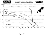
- Alkaline batteries are relatively low cost and have long shelf life. Furthermore, they are good in low power devices such as wall clocks and TV remote controls. However, these types of batteries are non-rechargeable/single use batteries that need to be disposed more frequently and therefore can be hazardous to the environment in terms of pollution. Additionally, these types of batteries are not very effective in high power devices. All non-rechargeable/single use alkaline batteries drop their output voltage when under load and hence products/devices such as flashlights/torches and cameras lose performance very quickly.
- Lithium primary batteries are non-reusable batteries that have lithium metal or lithium compounds as an anode.
- these types of batteries are particularly useful for high current devices. However, similar to alkaline batteries, these batteries are also non rechargeable/single use batteries that need to be disposed more frequently and therefore can be hazardous to the environment in terms of pollution. Furthermore, in terms of costs, these types of batteries are relatively expensive for a non-rechargeable/single use battery.
- NiMH nickel-metal hydride battery
- Ni-MH nickel-metal hydride battery
- NiCd battery or NiCad battery nickel-cadmium battery
- batteries available on the market which comprise a voltage level indicator. These indicators typically use a conductive strip under a clear section of the label, which is powered when one or both ends are pressed.
- a fixed 1.5V output will in some cases damage the electronics.
- Some electronic devices are built with the assumption that regular 1.5V disposable (Primary) batteries or 1.2V rechargeable (Secondary) batteries will be used. These batteries very quickly drop in output voltage under load.
- flashlight bulbs both LED and incandescent, are not generally manufactured to be able to operate at a full 1.5V Direct Current (DC) (or multiple of 1.5V if multiple batteries are used) but rather between 1.2V and 1.4V. Use of fixed 1.5V DC batteries will burn out some flashlight bulbs.
- DC Direct Current
- the self-discharge rate of a battery determines how much capacity remains after it has been sitting for a period of time since its last charge (or, in the case of primary cells, since manufacture).
- Secondary (rechargeable) cells often have a much higher self-discharge rate than primary (non-rechargeable cells).
- the self-discharge can be mitigated by having the user charge the battery before use.
- the capacity which has been lost to self-discharge cannot be recovered.
- US 8,314,590 discloses a battery that requires charging using a USB connection.
- CN201174405 discloses a battery that requires a special proprietary battery charger.
- those documents do not disclose a battery that could provide intelligent variable output.
- a battery that works by regulating a power source (such as a 3.7 V internal Li-ion cell) with micro-electronics to provide a suitable voltage output so that the user's devices/products using the battery will have a continuous high performance (and in case of a rechargeable battery, a continuous high performance until the battery needs a recharge).
- a power source such as a 3.7 V internal Li-ion cell
- micro-electronics to provide a suitable voltage output so that the user's devices/products using the battery will have a continuous high performance (and in case of a rechargeable battery, a continuous high performance until the battery needs a recharge).
- the output voltage of the battery is not regulated but is set to a constant 1.5V
- products/devices such as torches can burn out and therefore there is also a need for a battery that allows the output voltage to be regulated between a certain range, most preferably between 1.25V and 1.5V, so that the chance of products/devices such as torches being burnt out is eliminated or at least reduced.
- a battery that has electronics that regulate the input charge voltage so that the battery can be charged using existing NiMH/NiCd battery chargers.
- the term “battery” refers to a container or product comprising an internal chemical energy power source.
- the container or product may be in AA, AAA, C, D, 9V, lantern batteries or any other size and format.
- the term “power source” refers to a source of power for a battery comprising one or more cells, in which chemical energy is converted into electricity.
- a source of power for a battery comprising one or more cells, in which chemical energy is converted into electricity.
- the power source may optionally be rechargeable.
- Li-ion cell is intended to mean internal Lithium ion (Li-ion) cell that is one exemplary form of a power source for the battery.
- low-power ultra-low power
- ultra-low current ultra-low current
- use of the terms low-power/current, ultra-low power/current or the like, when used in relation to a circuit or component, should be taken to mean a component or circuit selected with the purpose of reducing the power consumption and/or current draw compared to other components that may be used. It is appreciated that the current/power draw is not the only deciding factor when choosing a component or designing a circuit. Therefore, a component or circuit described as "ultra-low” power / current does not need to be the lowest power / current (or whatever the case may be) component or circuit available.
- internal cell voltage, power source voltage or power source output voltage should be taken to mean the voltage across the terminals of the power source which connect to the voltage regulation device in certain embodiments of the technology. It is appreciated that a power source can comprise multiple cells, such as two Li-ion cells connected in series, however unless specifically stated otherwise, the internal cell voltage, power source voltage, or power source output voltage refers to the voltage as seen by the voltage regulation device, and not the voltage of the individual cells which the power source may comprise.
- switch should be interpreted in a broad sense which encompasses any device used to switch between operating modes of the voltage regulation device.
- the switch may comprise physical activation means such as switches, buttons, reed switches, insulating tape or similar.
- the switch may consist of electronic components such as transistors, comparators etc, or be a combination of mechanical and electronic means, such as the use of latching components as known to those skilled in the art in conjunction with a physical activation means.
- the invention resides in a battery as defined in claim 1.
- the switch comprises electronic components.
- the switch is configured to draw a low current.
- the low current may be a substantially negligible current draw relative to the stored energy of the battery.
- the switch comprises a comparator circuit. More preferably, the comparator circuit is configured to draw an ultra-low quiescent current.
- the switch is configured to detect the connection of a charger to the battery and to switch between the low-power operating mode and the active operating mode accordingly.
- the switch is configured to monitor a power source voltage and is configured to set the voltage regulation device to the low-power operating mode while the power source voltage is above a first predetermined threshold.
- the first predetermined voltage threshold is in the range of 1.2V to 1.4V, more preferably the first predetermined voltage threshold is substantially 1.3V.
- the switch is configured to monitor a power source voltage and is configured to set the voltage regulation device to the active operating mode while the power source voltage is below a second predetermined threshold.
- the second predetermined voltage threshold is in the range of 1.2V to 1.4V, more preferably the first predetermined voltage threshold is substantially 1.3V.
- the voltage regulation device does not actively regulate the output voltage.
- the battery is a rechargeable battery with a rechargeable power source.
- the power source is a Li-ion cell.
- the Li-ion cell is between 2.8 to 4.2 volts.
- the voltage regulation device comprises a programmable controller that is operatively connected to the positive terminal, the negative terminal, the power source and to one or more of the other electronic components of the voltage regulation device to send and receive input and output signals and thereby to sense and regulate an output voltage in the programmed variable level.
- the programmable controller is powered down while the voltage regulation device is in the low-power operating mode.
- the power source is rechargeable and the voltage regulation device comprises at least one voltage sensor configured to determine an input voltage that charges the power source, the at least one voltage sensor being operatively connected to the programmable controller, the programmable controller being adapted to receive at least one input signal from the at least one voltage sensor to regulate the input voltage.
- the voltage regulation device comprises at least one voltage sensor configured to determine a voltage level information of the power source and feed the voltage level information to the programmable controller.
- the programmable controller is programmed to provide a lower output voltage if the power source voltage has dropped to a pre-determined level.
- the voltage regulation device comprises at least one current sensor configured to determine an output current in a power source, the at least one current sensor being operatively connected to the programmable controller, the programmable controller being adapted to receive at least one input signal from the at least one current sensor and regulate the output voltage according to the output current at the programmed variable level.
- the voltage regulation device comprises at least one current sensor adapted to detect a connection to a battery charger, the at least one current sensor being operatively connected to the programmable controller.
- the voltage regulation device comprises at least one current sensor that is operatively connected to the programmable controller, the at least one current sensor is adapted to detect two or more of the following:
- the power source is rechargeable and the voltage regulation device comprises at least one charger sensor that is adapted to determine a connection to a battery charger by detecting a voltage from the battery charger, the at least one charge sensor being operatively connected to the programmable controller.
- the power source is rechargeable and the voltage regulation device comprises at least one charger sensor that is adapted to detect a voltage of a battery charger as a voltage level information and feed the voltage level information to the programmable controller in order to regulate the detected voltage of the battery charger for charging the power source.
- the voltage regulation device comprises at least one charger sensor that is adapted to detect a voltage of a battery charger as a voltage level information and feed the voltage level information to the programmable controller in order to regulate the detected voltage of the battery charger for charging the power source.
- the power source is rechargeable and the voltage regulation device comprises at least one charger sensor that is adapted to detect a voltage level information from a battery charger and feed the voltage level information to a programmable controller in order to regulate the output voltage according to the output current at the programmed variable level.
- the voltage regulation device comprises at least one charger sensor that is adapted to detect a voltage level information from a battery charger and feed the voltage level information to a programmable controller in order to regulate the output voltage according to the output current at the programmed variable level.
- the power source is rechargeable and the voltage regulation device comprises a voltage boost regulator that is operatively connected to the programmable controller, the programmable controller being adapted to receive at least one input signal from the voltage boost regulator to allow the voltage boost regulator to increase a voltage supplied from a battery charger to a higher voltage to charge the power source.
- the voltage regulation device comprises a voltage boost regulator that is operatively connected to the programmable controller, the programmable controller being adapted to receive at least one input signal from the voltage boost regulator to allow the voltage boost regulator to increase a voltage supplied from a battery charger to a higher voltage to charge the power source.
- the voltage buck regulator is operatively connected to the programmable controller, the programmable controller being adapted to receive at least one input signal from the voltage buck regulator to allow the voltage buck regulator to convert a voltage supplied by the power source to the output voltage of the battery.
- the voltage regulation device comprises a noise suppression circuit that is operatively connected to the programmable controller.
- the battery includes a voltage level indicator for providing an indication of the voltage level of the power source.
- the programmable controller is programmed to monitor the current and/or voltage level of the power source based on the input and output signals, and the programmable controller is operatively connected to the voltage level indicator in order provide an indication when the battery approaches the end of a discharge.
- the battery comprises a housing that is adapted to house at least the power source and the voltage regulation device.
- the battery is an AA battery or an AAA battery.
- the regulated output voltage is in a range between 1.2V and 1.5V.
- the regulated output voltage is in a range between 1.25V and 1.5V.
- FIG. 1 and Figure 2 show one embodiment of a battery (100) of the present invention comprising electronic components being operatively connected to each other.
- the battery (100) is an AA or AAA sized rechargeable lithium ion (Li-ion) battery of a predetermined voltage, preferably 2.8 volts (V) to 4.2 V, such as 3.7 V.
- the battery (100) includes a positive terminal (102) operatively connected by a voltage carrying means, such as a first wire (104) to a voltage regulation device (110) comprising a circuitry at least for voltage regulation.
- the voltage regulation device (110) may consist of multiple independent or interconnected circuits, and for simplicity will hereinafter be referred to as a voltage regulation circuit (110). Therefore, the first wire (104) electrically connects the positive terminal (102) of the battery to the voltage regulation circuit (110).
- the voltage regulation circuit (110) comprises electronic components in a suitable electrically connected arrangement.
- a circuit diagrams depicting two of the exemplary arrangements of the electronic components in the voltage regulation circuit (110) will be discussed later with reference to Figures 3 (a)-(c) and Figures 4 (a) - (i) .
- the voltage regulation circuit (110) is further connected by another voltage carrying means, preferably a second wire (106) to a negative terminal (112).
- the voltage regulation circuit (110) is also connected by at least one or more wires to each polarity (108) to an internal cell (114), which in this example is a 2.8 V to 4.2 V Li-ion cell such as a 3.7 V Li-ion cell.
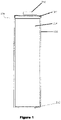
- the battery (100) further comprises housing or a shell (116) made out of any suitable material shaped and constructed to house the electronic components of the battery.
- the shell (116) surrounds, protects and encapsulates the electronic components of the battery (100).
- the shell (116) is made of a very thin (approximately 1mm thick) metal.
- the shell in this one example is shaped as an enclosed tube with a first (e.g. bottom) section and a second (e.g. top) section whereby the second section of the shell is attached after the assembly.
- the battery may comprise an additional thin shell layer (not pictured) used to display information such as branding, size, voltage and safety information. Typically this encompasses the shell (116) and has openings for the terminals (102, 112).
- the voltage regulation circuit (110) is at least adapted to regulate the output voltage in a programmed variable level and/or to sense and regulate the input voltage that charges the internal cell (114).
- the internal cell (114) is adapted to provide power to the voltage regulation circuit (110) via wires (108). These wires (108) are adapted to be used for both the charge and discharge of the internal cell (114).
- the internal cell (114) is preferably any power source, however the examples describe use of a Li-ion cell. A person skilled in the art will understand that a similar system may be developed for an alternative power source, rechargeable or otherwise.
- the voltage regulation circuit (110) may comprise at least one voltage sensor that configured to determine an input voltage that charges the power source, the power source being the internal cell (114).
- the voltage sensors(s) are operatively connected to the programmable controller.
- the programmable controller is adapted to receive at least one input signal from the at least one voltage sensor to regulate the input voltage.
- the voltage sensor(s) also feed information back to the switch to determine the operating mode of the voltage regulation circuit.
- the voltage sensor may be configured to determine a voltage level information of the power source and feed the voltage level information to the programmable controller.
- the programmable controller is programmed to provide a regulated battery output voltage which may be higher, lower or substantially equal to the output voltage of the power source.
- the voltage regulation circuit (110) may comprise at least current sensor that is configured to determine an output current in the internal cell (114).
- the at least one current sensor is also operatively connected to a programmable controller that is adapted to receive at least one input signal from the at least one current sensor and regulate the output voltage according to the output current at the programmed variable level.
- the current sensor(s) may be adapted to detect a connection to a battery charger when operatively connected to the programmable controller and/or the switch.
- the current sensor (s) may also be adapted to detect two or more of the following:
- the voltage regulation circuit (110) will be described with reference to several exemplary embodiments. Although, the circuit has been referred to as a voltage regulation circuit (110), it is to be understood that voltage regulation is not necessarily the sole purpose of the voltage regulation circuit (100). Some of the other functions of the voltage regulation circuit (110) have been described later.
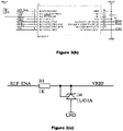
- FIGS 3 (a)-(c) together show the circuit diagram of one form of a voltage regulation circuit (110) that may be used in the battery (100) of the present invention.
- the voltage regulation circuit (110) comprises several electronic components that are electronically and operatively connected to each other. Exemplary values and units of most of those electronic components are also shown. To a person skilled in the art, component values, arrangement and the functionality of the voltage regulation circuit (110) will be self-explanatory upon consideration of the schematic diagrams of Figures 3 (a)-(c) and therefore need not be discussed in detail.
- the voltage regulation circuit (110) may comprise an electronic controller which can be a programmable controller, for example a microcontroller (U1), such as a PIC16F616 microcontroller, that is adapted to send and receive several input and output signals from the circuit of Figure 3(a) and (c) .
- the microcontroller (U1) is operatively connected to the positive terminal, the negative terminal, the power source and to one or more of the other electronic components of the voltage regulation device in order to send and receive input and output signals and thereby to sense and regulate the output voltage in the programmed variable level.
- a first component (P1) on the left represents the terminals (102 and 112) of the battery (100) that are adapted to connect a user's product/device (not shown) in order to supply power to the user's product/device.
- the first component (P1) is also adapted to connect to a battery charger (not shown) in order to charge a power source/ internal cell (114) such as a Li-ion cell that is internal to the battery (100).
- a second component (P2) on the right that connects to the power source/ internal cell (114) such as the Li-ion cell that is internal to the battery (100).
- Capacitors (C1, C2, C3 and C4) and inductor (L1) are preferably positioned in the circuit as shown in the Figure 2 (a). These components form a noise suppression circuit that is operatively connected to the microcontroller (U1) so that the microcontroller (U1) can receive at least one input signal from the noise suppression circuit.
- the noise suppression circuit provides for noise suppression, particularly spurious electronic noise suppression.
- the voltage regulation circuit (110) comprises at least one regulator.
- the regulator(s) being operatively connected to the programmable controller (U1) and is adapted to be activated by the programmable controller (U1) at a preset battery output level in order to regulate the output voltage. This will now be described in more detail.
- a voltage boost regulator is formed by an N-channel MOSFET (Q2), resistors (R12, R4, R3, R14), diode (D2) and capacitor (C6).
- the voltage boost regulator is operatively connected to microcontroller (U1) and the microcontroller (U1) is adapted to receive at least one input signal from the voltage boost regulator to allow the voltage boost regulator to increase a voltage supplied from a battery charger to a higher voltage to charge the internal cell (114).
- the voltage boost regulator is adapted to increase the voltage from a first level supplied from an external battery charger (for example approximately 1.6V DC) to a second higher voltage that is needed for charging the internal cell (> 3.5V DC).
- the voltage boost regulator is controlled by the first control signal (PWM1), which is a Pulse Width Modulated signal and provides its status to the micro-controller (U1) via a first current signal (CUR1).
- Resistors (R6 and R15) and capacitor (C8) together define a first current sensing circuit configured to determine or sense:
- the first current sensing circuit provides its status to the micro-controller (U1) via a second current signal (CUR2).
- a voltage buck regulator is formed by a P-channel MOSFET (Q1), diode (D2) and resistors (R2 and R16).
- the voltage buck regulator is operatively connected to the microcontroller (U1) and the microcontroller (U1) is adapted to receive at least one input signal from the voltage buck regulator to allow the voltage buck regulator to convert a voltage supplied by the internal cell (110) to the output voltage of the battery (100).
- the voltage buck regulator is adapted to convert the voltage supplied by the Li-ion cell (3.7V DC) to the regulator battery output (up to 1.5V DC).
- the battery output voltage may vary depending on the current being used by the user's product /devices.
- Such variable regulation is controlled by the micro-controller (U1) via a second control signal, which is a Pulse Width Modulated signal (described in more detail below).
- the micro-controller (U1) receives feedback as to the regulated output voltage from the buck regulator through resistor (R1) and capacitor (C9).
- Resistors (R13 and R5) and capacitor (C7) together define a second current sensing circuit adapted to sense/detect:
- This circuit provides its status to the micro-controller (U1) via a third current signal (CUR3).
- CUR3 third current signal
- a circuit for regulating a voltage of the microcontroller (U1) is shown in the Figure 3(c) .
- This microcontroller voltage regulation circuit comprises resistor (R8) and shunt regulator (D4) and this circuit provides its status to the micro-controller (U1) via a voltage signal (V REF ).
- the micro-controller (U1) comprises resistor (R7) and capacitor (C5).
- Figure 3(b) shows how the microcontroller (U1) receives several input signals from the circuits of Figure 3(a) and (c) .
- the microcontroller (U1) gets feedback from the current signals (CUR1, CUR2 and CUR 3) and provides a first and second control signal (PWM1 and PWM2) of Figure 3(a) to ensure correct output voltage of the battery (100) when in use and also to ensure correct charging of the internal cell (114) when the battery (100) is connected to the charger (not shown).
- the output voltage of the battery is set via the second control signal (PWM2) at a programmed level between 1.2 V DC and 1.5V DC to ensure the best possible usability.
- PWM2 the second control signal
- This ability to control/regulate voltage at a programmed level between 1.2V and 1.5V DC is a highly advantageous feature of the present invention. This is because if the output voltage was set to a fixed 1.5V DC, it may burn out some electronics. Similarly, if the output voltage is set at a lower voltage, the battery may not provide enough voltage for some electronics.
- a battery (100) with a regulated output voltage is achieved.
- the battery (100) using the voltage regulation circuit (110) as discussed above is able to output a high amount of power until it is fully discharged (or 'flat'). This is advantageous over previously known non rechargeable/single use batteries as well as all other NiMH/NiCD rechargeable batteries which slowly reduce the output voltage as they discharge (or 'go flat') thereby affecting how the user's product/device might work.
- the battery (100) using the voltage regulation circuit (110) as discussed above can provide a regulated voltage input which means that the battery (100) can be charged with all commercially available NiMH/NiCD battery chargers. This can be an additional advantage over previously known circuit regulated batteries that require special chargers. Alternatively, special chargers can be developed for the batteries if desired.
- the buck regulator (formed by Q1, D2 and L1) may be left in a state where the PFET is held on.
- resistor (R2) may be desirable to increase the impedance of resistor (R2) to reduce current draw.
- the micro-controller may not be required and can be put into a low-power state, whereby it is substantially inactive until a switch device (not shown) such as a quiescent current comparator, for example an ultra-low quiescent current comparator, detects a change in the output voltage and returns the microcontroller to its active mode.
- a switch device such as a quiescent current comparator, for example an ultra-low quiescent current comparator, detects a change in the output voltage and returns the microcontroller to its active mode.
- an additional component such as a resistor to bias the gate of the PFET (Q1) towards an on or conducting state while micro-controller is inactive.
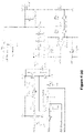
- FIGS 4 (a) - (i) together show a circuit diagram of an alternative form of the voltage regulation circuit (110) that is used in the battery (100) of the present invention.
- the voltage regulation circuit (110) comprises several electronic components that are electronically and operatively connected to each other. Exemplary values and units of most of those electronic components are also shown in those figures. To a person skilled in the art, the component values, arrangement and functionality of the voltage regulation circuit (110) will be self-explanatory upon consideration of the schematic diagrams of Figures 4(a)-(i) and therefore need not be discussed in detail.
- the voltage regulation circuit (110) of this second preferred embodiment comprises a microcontroller (U5) that is adapted to send and receive several input and output signals from the circuits of Figures 4(a) to (h) .
- a first component (P1) represents the terminals (102 and 112) of the battery (100) that is adapted to be connected to a user's product/device (not shown) in order to supply power to the user's product/device.
- the first component (P1) is also adapted to connect to a battery charger (not shown) in order to charge the power source i.e., internal cell (114) such as Li-ion cell that is internal to the battery (100).
- Figure 4(a) comprises an Output Current Sensor, Low Dropout Linear Regulator (i.e. LDO Regulator) and Synchronous Buck Regulator/Voltage Boost and Pass through. These components will be discussed later in more detail.
- LDO Regulator Low Dropout Linear Regulator
- Synchronous Buck Regulator/Voltage Boost and Pass through These components will be discussed later in more detail.
- Figure 4 (b) contains a second component (P2) that connects to the internal cell (114) that is internal to the battery (110).
- the circuit of Figure 4(b) is adapted to provide voltage references that are required by other circuit sections.
- a fixed voltage regulator outputs a 2.048 volts DC to VREF 2. This voltage is divided using resistors (R21, R12, R18 and R15) to provide voltage references of 1.55 VDC and 1.4 VDC.
- resistors R21, R12, R18 and R15
- These voltage references are used by at least one or more of; the microcontroller (U5) of Figure 4(i) , the current sensor of Figure 6 and the synchronous buck regulator/voltage booster of Figure 8 .
- Figures 4 (c) - (e) show the power connections for integrated circuits U3, U7 and U14 respectively. They are powered directly from the second component (P2) via the power source V CELL.
- Figure 4 (f) is an example circuit for sensing the battery output voltage and is used as the Charger Sensor Circuit to detect an external charger. This circuit and its applications will be discussed later in more detail.
- Figure 4 (g) is an example circuit for sensing the voltage of the internal cell (114) and is used as the Internal Cell Voltage Sensor. This circuit and its applications will be discussed later in more detail.
- Figure 4 (h) is a fixed 3.3 V DC regulator to power the microcontroller (U5).
- 4 (i) shows how a programmable microcontroller (U5) receives several inputs from the circuits of Figures 4 (a) to 4 (h) .
- the voltage regulation circuit of this second embodiment can provide several key features including intelligent battery output; intelligent battery charging; voltage drop when the power source approaches the end of discharge and battery level indication.
- Intelligent battery output is one of the features of the battery (100) that may be achieved through the voltage regulation circuit (110) of the second embodiment.
- a fixed 1.5 V output will in some cases damage the electronics. Some flashlights will burn out the bulbs with a fixed 1.5 V battery/batteries.
- the battery (100) is adapted to sense the output current and adjust the output voltage according to the output current.
- An example of a possible voltage drop for an AA battery is as per below.
- the battery output current can be monitored by a number of methods.
- One method is to use a very low ohms value resistor on either the positive or the negative output, and measure the voltage across the resistor. As the current increases, the voltage across the resistor will increase. The feedback can then be used to adjust the voltage regulator and lower the output voltage.
- the voltage regulation circuit (110) comprises at least one regulator that is operatively connected to the programmable controller (U5) and is adapted to be activated by the programmable controller (U5) at a preset battery output level in order to regulate the output voltage. This will now be described in more detail.
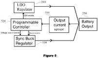
- the block diagram of Figure 5 corresponds to the circuit of Figure 4(a) that has both a LDO regulator (510) and a Voltage Buck Regulator, i.e. a Synchronous Buck Regulator (530).
- the LDO regulator (510) is included in this embodiment for battery efficiency at low currents. It is possible to have only one regulator or more than two regulators.
- the programmable controller (520) when there is no current drain or a pre-determined low current drain the programmable controller (520) which is same as the microcontroller (U5) of Figure 4(i) , may activate the LDO regulator (510) to regulate the output voltage and disable the Synchronous Buck Regulator (530).
- the LDO Regulator (510) output is sensed for the current flow and provided as the battery output (550).
- An Output Current Sensor (540) is fed back to the programmable controller (520). If the output current exceeds a pre-determined current drain, the programmable controller (520) activates the Synchronous Buck Regulator (530) and disables the LDO regulator (510).
- the LDO regulator (510) is more efficient and for medium to high current outputs, the Synchronous Buck Regulator (530) is more efficient.
- the buck regulator can run in a 100% duty cycle or always on mode and only have reduced losses associated with the low on-resistance of the P-FET (Q2) and the resistance of the inductor (L1). In this low-power mode it may be desirable to disable or shut down non-active circuitry to further reduce the quiescent current draw and increase efficiency.
- a switch configured to draw a low current can then be used to return the circuit to its active operation mode once the output voltage or the cell voltage reaches a pre-determined threshold, or an external power source is detected such as an external charger.
- the circuit of Figure 6 is an example of the Output Current Sensor (540) of Figure 5 having the battery output (550) as P1.
- This circuit of the Output Current Sensor (540) of Figure 6 can also be seen in Figure 4(a) .
- the signals "I EN", "LOAD 1" and "VREF 2" all connect to the microcontroller (U5).
- the current is measured by measuring the voltage drop across resistor (R1) using an operational amplifier (U3A) with the resulting voltage being provided to microcontroller (U5) where programming determines the actual current value.
- the higher the current flow through resistor (R1), the higher the voltage difference across resistor (R1) (as per Ohm's Law Voltage (V) Current (I) x Resistance (R)).
- the operational amplifier (U3A) amplifies the voltage difference measured across resistor (R1) to provide greater measurement accuracy.
- the circuit of Figure 7 is an example of a circuit for the LDO Regulator (U15) which is the same as the LDO regulator (510) in the block diagram of Figure 5 .
- This circuit of Figure 7 can also be seen in Figure 4(a) .
- the "V Cell” signal is connected to the internal cell (114)
- the "LDO EN” is connected to the microcontroller (U5), and may include an optional biasing means such as a resistor (not shown) to ensure the regulator remains in a desirable state should the micro-controller shut down
- P1 is the battery output (550).
- the LDO Regulator (U15) will act as a fixed voltage regulator to ensure maximum efficiency at low loads.
- the LDO regulator (U15) is enabled or disabled by the programmable controller (520), i.e. the microcontroller (U5).
- the LDO regulator (U15) will be enabled, when the battery (100) has a low current drain and will be disabled when the battery (100) has a high current drain.
- the Synchronous Buck Regulator (530) will take over.
- the LDO regulator (U15) in this example of Figure 7 is a fixed voltage regulator. However, a person skilled in the art will appreciate that the invention will also work if the LDO regulator was a variable voltage regulator set for a fixed output such as 1.5 V DC.
- the circuit of Figure 8 is an example of a Synchronous Buck Regulator (530) of Figure 5 .
- This circuit of Figure 8 can also be seen in Figure 4(a) .
- the Synchronous Buck Regulator (530) will be activated by the microcontroller (U5) at a preset battery output current level.
- the "V Cell” signal is connected to the internal cell (114).
- the signals "PWM HI”, "SHNT REG EN” and "PWM LOW” signals all connect to the microcontroller (U5) as shown in Figure 4(i) .
- the battery output is shown as P1.
- the signal "V1V55" is connected to a fixed 1.55 V DC reference.
- the programming of the microcontroller (U5) will turn off the LDO Regulator (U15) and regulate the output using the Synchronous Buck Regulator (530). This is done by turning off the operational amplifier (U3B) and the microcontroller (U5) will control the output voltage via the operational amplifier (U1), N channel MOSFET (Q1), P channel MOSFET (Q2) and inductor (L1).
- inductor (L1), N-FET (Q1), and P-FET (Q2) can form a boost regulator for charging the internal cell or power source from an external charger.
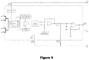
- Figure 9 shows an alternative form of the output current sensor (540) to measure the battery output current.
- the circuit of Figure 9 uses a Hall Effect Sensor (represented by X in Figure 9 ) to measure the magnetic field through a conductor that carries a current which eliminates the need for the resistor (R1).
- the magnetic field strength around the conductor is proportional to the current flow through it. As the current increases, the magnetic field strength increases. The current flows from IP+ to IP-.
- An operating mode switch allows for a low self-discharge while the battery is in storage or when the power source output voltage is substantially similar to the desired battery output voltage.
- the switch may comprise or take the form of a physical switch such as used in the battery capacity level indicators well known in the art.
- the switch may comprise or take the form of an electronic switch such as a quiescent current comparator, for example an ultra-low quiescent current comparator.
- a physical switch may have a negligible current draw, while an electronic switch could be designed to have a low or ultra-low current draw.
- the voltage regulation device has two operating modes:
- the voltage regulation device is configured to operate in a third "disconnection" mode where the battery terminals are operatively disconnected from the power source as described below.
- the output of the power source may be operatively disconnected from the terminals of the battery. This means that an electronic load applied to the terminals does not discharge the battery further.
- the disconnection of the output of the power source from the terminals may be provided by a series of electronic components. Furthermore, in the disconnection mode, it will be appreciated that a current path may be provided to charge the power source. For example, the output may be disconnected by electronic components such as diodes, transistors, of FETs which are configured to allow current to flow in a single direction as known to those skilled in the art.
- the physical switch may be configured to disconnect the power source (114) from the terminals (102, 112) or disable the voltage regulation device (110).
- a user may press the contact sensitive regions of the battery capacity level indicator to enable the intelligent battery and press the contact sensitive regions of the battery capacity level indicator once more to disable the intelligent battery.
- the switch may comprise or take the form of a momentary contact switch with an accompanying latch circuit to hold the voltage regulation circuit (110) in the desired operational state. It is also an aspect of the present technology to allow the switch to disconnect the power source from the output terminals. This is further described later with reference to figure 23 .
- the switch is configured to disable circuit elements which are not required in the low-power mode, such as the micro-controller. In doing so the quiescent current draw of the battery can be reduced.
- the switch comprises or take the form of an automatic electronic switch such as an ultra-low quiescent current comparator.
- the switch has two key purposes as explained below.
- the above table gives an example of the output of the preferred embodiment where the voltage regulation device has been configured to operate in the low-power mode while the power source voltage is above a pre-defined voltage threshold.
- the voltage regulation device is switched into its active mode of operation and the battery output voltage is regulated at a voltage substantially similar to the pre-defined voltage threshold until the internal power source is flattened.
- the pre-defined voltage threshold is 1.3V. In other embodiments the voltage threshold may be lower or higher depending on the operating voltage of the battery and the voltage at which it is determined a boost is required.
- the above example uses a single voltage threshold, however it is appreciated that in other embodiments there is a second (upper) voltage threshold such that, when the power source voltage is above this threshold, the voltage regulation device switches into its active mode of operation to reduce the battery output voltage.
- the second voltage threshold is substantially 1.5V. It will be appreciated that this value may differ depending, for example, on the operating voltage of the battery or other factors.
- the pre-defined range of acceptable voltages depends on the desired output voltage of the battery, for example a 9V battery could have preferred output voltages in the range of 8-9 V.
- the switch can be included in any of the disclosed embodiments.
- Intelligent battery charging is another feature that can be achieved from the second preferred embodiment of the voltage regulation circuit (110).
- the battery (100) of the present invention uses electronic circuitry to sense a voltage from the battery charger, such as a standard NiMH or Li-ion battery charger and regulates this voltage to charge the internal cell (114).
- a voltage from the battery charger such as a standard NiMH or Li-ion battery charger
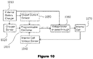
- the voltage regulation circuit comprises at least one charger sensor (1020) that is operatively connected to the programmable controller (1030) which is same as the microcontroller (U5) and is adapted to determine a connection to an external battery charger (1010) by detecting a voltage from the external battery charger (1010).
- the charger sensor(s) (1020) may be adapted to detect a voltage of the external battery charger (1010) as a voltage level information and feed that voltage level information to the microcontroller (U5) in order to regulate the detected voltage of the battery charger (1010) for charging the internal cell (1070) (which is same as internal cell (114)) .
- the charger sensor(s) (1020) may also be adapted to detect a voltage level information from an external battery charger (1010) and feed the voltage level information to the microcontroller (U5) in order to regulate the output voltage according to the output current at the programmed variable level.
- the charger sensor (1020) detects the voltage from the external battery charger (1010) and sends a signal to a programmable controller (1030) which is the same as the microcontroller (U5) of Figure 4 (i) .
- the signal provides information to the programmable controller (1030) regarding the type of external battery charger (1010) that is connected. If the connected external battery charger (1010) is a first power source type of battery charger (e.g. a Li-ion charger) and the internal cell (1070) (which is same as internal cell (114) of Figures 1 and 2 ) is also of the same first power source type (e.g.
- the programmable controller/microcontroller (1030, U5) will activate a pass through to effectively directly connect the charger to the internal cell (1070). If the connected external battery charger (1010) is a second power source type of battery charger (e.g. a NiMH battery charger) and the internal cell of the battery is of a different power source type (e.g. Li-ion cell), the programmable controller/microcontroller (1030, U5) will activate a Voltage Boost or Pass through circuit (1060) to adjust the charge voltage to enable charging of the different power source (e.g. increase the lower NiMH charge voltage up to the higher Li-ion charge voltage).
- a Voltage Boost or Pass through circuit (1060) to adjust the charge voltage to enable charging of the different power source (e.g. increase the lower NiMH charge voltage up to the higher Li-ion charge voltage).
- the circuit of Figure 4(f) is an example of the Charge Sensor (1020).
- the "VOUT” signal connects to the external battery charger (1010) and as shown in Figure 4(i) , the "V OUT ADC” signal connects to the microcontroller (U5).
- the Voltage Boost or Pass through Circuit (1060) of this embodiment is the same circuit as the Synchronous Buck Regulator (530) as described above with reference to Figure 8 , which also appears in Figure 4 (a) .
- the "V CELL” signal is connected to the internal cell (1070).
- the "PWM HI”, SHNT REG EN” and PWM LOW” signals all connect to the microcontroller (U5).
- P1 is the battery output.
- the “V1V55” is connected to fixed 1.55V DC reference.
- the “VOUT” signal is connected to the external battery charger (1010).
- a Li-ion charger will output a higher voltage than a NiMH charger and the programming of the microcontroller (U5) determines which type of external battery charger (1010) is connected. The microcontroller (U5) may then determine if the voltage needs to be adjusted to allow charging of the specific type of power source being used by the battery and controls the voltage regulation circuit to provide the required voltage level for charging the specific power source.
- microcontroller (U5) determines that a Li-ion charger is connected and the internal cell (114) is Li-ion, an output if the microcontroller (U5) will fully switch on P Channel MOSFET (Q2) and switch off N Channel MOSFET (Q1).
- the Li-ion charger is then connected to the internal cell (1070 via inductor (L1) and P Channel MOSFET (Q2) which are both effectively short circuit.
- the battery charger will act/charge like a Li-ion battery has been inserted.
- N Channel MOSFET is used to create a voltage booster from the signal "VOUT" (battery terminals and battery charger) side to the "VCELL" signal (internal cell (1170)).
- the inductor (L1) is used as a boost indicator so when the N Channel MOSFET (Q1) is on, current flows into inductor (L1) from the charge source.
- the circuit for the Output Current Sensor (1050) here is the same circuit as the Output Current Sensor (540) described above with reference to Figures 5 and 6 , which also appears in Figure 4(a) .
- Battery output and connection to the external battery charger (1010) is shown as P1 in Figure 6 .
- the signals "I EN", LOAD1" and VREF 2" all connect to the microcontroller (U5) as shown in Figure 4(i) .
- the current is measured by measuring the voltage drop across resistor (R1) using an operational amplifier (U3A) with the resulting voltage being provided to microcontroller U5 where programming determines the actual current value.
- the higher the current flow through R1, the higher the voltage difference across resistor (R1) (as per Ohm's Law Voltage (V) Current (I) x Resistance (R)).
- the operational amplifier (U3A) amplifies the voltage difference measured across resistor (R1) to provide greater measurement accuracy.
- the controller When the internal cell (1070) is fully charged the controller is able to sense the lower current being drawn by the internal cell (1070) via the resistor (R1) and operational amplifier (U3A) and at this point the microcontroller (U5) turns on P Channel MOSFET (Q2) (the P Channel MOSFET (Q2) acts as a shunt regulator) to bypass the charge source or to indicate to the charge source that the internal cell (1070) is fully charged.
- P Channel MOSFET Q2
- the P Channel MOSFET (Q2) acts as a shunt regulator
- the circuit of Figure 4(g) is an example of the voltage sensor, i.e., an Internal Cell Voltage Sensor (1040).
- the signal “V-CELL” connects to the internal cell (1070) and the signal “VOUT ADC” connects to the programmable controller (1030), i.e. the microcontroller (U5).
- the voltage level of the internal power source, i.e. the internal cell (1070) is sensed via resistors (R17 and R20) and that voltage is fed to the microcontroller (U5).
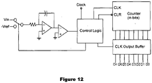
- the external battery charger can also be detected using other type of comparators such as a flash convertor or multi comparators (see Figure 11 ) or Dual Slope ADC (see Figure 12 ).
- comparators such as a flash convertor or multi comparators (see Figure 11 ) or Dual Slope ADC (see Figure 12 ).
- the internal cell (1070) can also be charged from an external battery charger (such as a NiMH charger) using other circuit designs such as via a transformer based converter such as a fly-back transformer.
- an external battery charger such as a NiMH charger
- transformer based converter such as a fly-back transformer
- FIG. 13 An example of a transformer based circuit is shown in Figure 13 .
- the internal cell can also be charged from an external battery charger using other circuit designs such as Single -Ended Primary Inductor Convertor (SEPIC) or a 'CUK convertor. These convertors will boost the battery charger voltage to enable an internal cell with a higher or same voltage as the charger to be charged.
- SEPIC Single -Ended Primary Inductor Convertor
- 'CUK 'CUK circuit
- the battery of this form of the present invention can monitor the internal power source and when it approaches the end of the discharge (i.e. it is almost flat), the battery voltage will be reduced to indicate to the user that it requires a recharge.
- the battery of this form of the present invention can reduce the output voltage regardless of the output current. This means that if the output current is high and if the battery output is reduced, a further reduction is still applied.
- An example of a possible voltage drop for an AA battery according to the present invention is as per below.
- the voltage of the internal cell (1510) (which is same as internal cell (114) of Figures 1 and 2 ) is sensed by the voltage sensor (1520) and this information (the internal cell voltage) is fed to the programmable controller (1530), which is same as the microcontroller (U5) of Figure 4 (i) . If the voltage of the internal cell (1510) has dropped to a pre-determined level that is pre-programmed into the microcontroller (U5), the microcontroller (U5) will lower the output of the Synchronous Buck Regulator (1560) which will provide a lower battery output voltage.
- the voltage drop programmed for the low internal cell (1510) could be added to the voltage drop programmed as part of the "Intelligent Output".
- Figure 15 shows use of the output current sensor (1540), that is optional.
- the circuit of Figure 4(g) is an example of the voltage sensor (an Internal Cell Voltage Sensor).
- the "VCELL” signal connects to the internal cell (1510) and the “V OUT ADC” signal connects to the microcontroller (U5).
- the internal power source or the internal cell (1510) voltage level is sensed via resistors (R17 and R20) and this voltage is fed to the microcontroller (U5) in the same way as described above in the Intelligent Battery Output section.
- the circuit for the Synchronous Buck Regulator (1560) here is the same circuit as the circuit of Figure 8 that also appears in Figure 4(a) .
- V CELL is connected to the internal cell.
- PWM HI is the Battery Output.
- V1V55 is connected to a fixed 1.55V DC reference.
- VOUT is connected to the battery output terminals.
- the circuit of Figure 4(a) will more effectively reduce the output voltage while the battery is under load and the Synchronous Buck Regulator (1560) circuit is being used rather than the LDO regulator (U15).
- the LDO regulator (U15) can be replaced with a variable LDO regulator rather than a fixed output regulator that is shown in the circuit diagram of Figure 4(a) .
- the programming of the microcontroller (U5) would lower the output voltage as it regulates the output using a synchronous buck regulator (1560).
- the voltage is dropped (regulated) by turning the operational amplifier (U3B) off and the microcontroller (U5) would control the voltage via operational amplifier (U1), N Channel MOSFET (Q1), P Channel MOSFET (Q2) and inductor (L1).
- the internal cell voltage can also be measured using other type of comparators such as a flash convertor or multi comparators (see Figure 11 ) or Dual Slope ADC (see Figure 12 ).
- comparators such as a flash convertor or multi comparators (see Figure 11 ) or Dual Slope ADC (see Figure 12 ).
- the battery (100) of the present invention can include on a battery surface any form of indicators that is adapted to indicate or show the charge or power level of the battery.
- a voltage level indicator such as a voltage level meter showing the user how much power is left in the battery may be used.
- this internal cell (114) is Li-ion
- the battery voltage to measure is as follows:
- the internal cell (114) voltage can be measured by various methods. One way through the circuit of Figure 4(g) .
- the voltage of the internal cell (114) such as a Li-ion cell is directly measured via resistors (R17 and R20) and fed to microcontroller (U5) where the level of power left can be calculated by the programming of the microcontroller (U5).
- thermochromic ink covered conductive strip can be installed on the surface if the battery (100) under a clear film or clear section of the label and when one or both ends are pressed, a circuit is completed and the voltage applied to each end of the conductive film.
- the thermochromic ink would change colour as it indicates the temperature of the conductive film that would be proportional to the current flowing through the film.
- a single thermochromic ink or multiple inks could be used.
- the battery level indicator can also serve as an input to a latch circuit for selecting between the operating modes of the voltage regulation circuit. This embodiment in shown in figure 22 and discussed further later in this document.
- FIG. 16 An example of a current limit circuit is shown in Figure 16 .
- Constant current circuit-current 50mA.
- the load is driven with a constant current.
- Other ways of measuring include using comparators such as a single or multi slope comparators or a flash convertor.
- the level of power left in the internal cell (114) can be shown using various methods. Another way is to use small LED's built in to the battery case that are programmed by the microcontroller (U5) to show the voltage level.
- the LED's could be ultra-low current and remain on at all times, alternatively the LEDs could be switched on periodically or they could be activated on a section of the battery to complete a circuit. This could be done using a conductive film under the battery label.
- FIG. 17 An example of a circuit to show voltage level is shown in Figure 17 .
- Battery level indication may equally be applied to the battery (100) that uses the voltage regulation circuit (110) as described in the first embodiment of the invention.
- Table 4 below shows how the battery of the present invention compares with previously known batteries when applied in different products:
- Table 4 Product Alkaline Lithium NiMH Present invention using a Li-Ion cell Bluetooth speaker Satisfactory Excellent Satisfactory Excellent Torch (incandescent) Poor Excellent Satisfactory Excellent Torch (LED) Poor Excellent Satisfactory Excellent Remote control car Poor Excellent Satisfactory Excellent Walkie talkie Poor Excellent Satisfactory Excellent Wii game controller Satisfactory Excellent Satisfactory Excellent TV remote control Excellent Excellent Satisfactory Good Wall clock Excellent Excellent Satisfactory Good Wireless mouse/keyboard Satisfactory Good Satisfactory Excellent Camera flash unit Poor Poor to Good Satisfactory Excellent Stored 3 months Excellent Excellent Good Excellent Stored 6 months Excellent Excellent Good Excellent Stored 12 months Excellent Excellent Good/ Satisfactory Good
- Figure 18 is a graph showing actual data for several types of AA batteries when tested in a digital compact camera. The results in the graph are from tests carried out with 2 x AA batteries in a digital compact camera until the camera would no longer take photos with the flash turned on.
- the dark section of the bar graph shows the number of photos with the flash that were taken prior to the low battery being displayed.
- the camera went into a power saving mode and the display turned off between photos when the flash was recharging.
- the recharge time was also longer.
- the lighter section of the bar graph shows the number of photos taken when the low battery level was on.
- the battery of the present invention (referred to as 'BOOST FP') was ready to take photos quickly for all photos. BOOST FP tested to be long lasting, fast flash recharge time and capable of taking more photos between recharges than any other rechargeable battery.
- Figure 19 is the graph showing data for several types of AAA batteries when tested in a CREE LED flashlight. Specifically, the results in the graph are from tests carried out with 3 x AAA batteries in a CREE LED flashlight.
- the brightness was measured by a Lux meter and the battery of the present invention (referred to as 'BOOST FP') brightness was taken as the 100% baseline. Subsequent readings were taken as a percentage of this baseline.
- the left side of the graph shows the brightness when first turned on. As time progressed, the brightness of the flashlight reduced while the batteries slowly started discharging (or 'got flatter').
- the other batteries dropped their output very quickly resulting in a much dimmer flashlight output after a very short time (e.g. within a few minutes, such as 1-15, or 2-10 minutes).
- the graph of Figure 19 shows the relative brightness overtime for a CREE LED flashlight with AAA batteries, clearly showing that no other battery tested provided full brightness as long as the BOOST FP.
- Figure 20 is a graph showing expected results for several types of batteries when used over time to recharge external camera flash with continuous use. The lower the line in the graph, the faster the camera charges the flash.
- the battery of the present invention is referred to a 'Revolt Pro' in that graph. As it can be seen from Figure 20 , with use of the battery of the present invention, it is no longer necessary for the user to wait longer and longer for their camera flash to recharge and the user's camera flash will recharge at the same fast rate until the battery is flat.
- Figure 21 is a block diagram showing an exemplary configuration of a circuit for boosting the output voltage and an electronic switch for reducing the quiescent current draw. It will now be explained in further detail.
- the circuit of Figure 21 comprises a voltage regulation device comprised of the controller and voltage boost (2120), at least one inductor (2130), at least one transistor (2150) and at least one sensor (2140). It is also appreciated that the voltage regulation device may comprise a switch (not shown), this embodiment is further illustrated in figure 22 . However it should be considered that the controller and voltage boost (2120) block also comprises the switch in this embodiment.
- the internal cell (2110) comprises the power source, such as a lithium cell, and it may also comprise other components such as the current sensor described in figures 3 and 4 .
- the battery output (2160) comprises the terminals of the battery, and may also comprise an output current sensor as described in figures 3 and 4
- the internal cell/power source (2110) as shown in figure 21 is operatively connected to a controller and a voltage boost (2120).
- the controller is configured to measure the internal cell (2110) voltage and battery output (2160) voltage via the voltage sensor (2140). If the internal cell voltage is within a pre-determined range of acceptable output voltage (for example 1.3-1.5V) the PFET (2150) is turned on and current is passed through the inductor (2130) and the PFET (2150) to the battery output (2160).
- the controller (2120) activates an internal NFET or similar (not shown) and operates in a voltage boost mode, with the voltage sensor (2140) providing feedback as to the battery output (2160) voltage.
- FIG. 4 (g) One configuration of the voltage sensor (2140) is as shown in figure 4 (g) , whereby the voltage is divided by a pair resistors (R17, R20) and passed directly to the micro-controller for comparison with internally programmed thresholds.
- the controller and voltage boost circuit (2120) comprises at least one switch as previously described.
- the switch is an ultra-low quiescent current comparator (not shown) with a high impedance voltage divider (not shown) from the internal cell (2110).
- the comparator compares the internal cell voltage with a voltage reference (such as 1.3V) and provides signal to the controller and voltage boost block (2120).
- the voltage reference can be generated by any low current reference methods known in the art.
- the controller and voltage boost circuit can be powered down (except for the comparator).
- This powered down state is referred to as the low-power operation mode throughout this document.
- the gate of the PFET (2150) is held low ensuring that it remains in a conducting state.
- the gate of the internal NFET (not shown) is also held low to ensure it does not turn on.
- the ultra-low quiescent current comparator switches the controller and voltage boost circuit (2120) into its operating mode and voltage regulation commences.
- the voltage sensor (2140) may pass a signal to the controller and voltage boost block (2120) to indicate the connection of an external power source. This signal may also transition the controller and voltage boost block (2120) into its active mode.
- the configuration shown in the block diagram of figure 21 may be adjusted to accommodate the buck regulation and internal cell charging features disclosed in previous figures.
- a synchronous buck regulator for reducing the internal cell (2110) voltage to a predetermined battery output voltage (2160) is created.
- additional components and control lines can be added to support both buck and boost regulation in one or both directions.
- Figure 22 shows an exemplary block diagram wherein the switch is comprised of a press button (2230) and an electronic latch (2220).
- the switch in the embodiment of Figure 22 may comprise a battery voltage level indicator as well known in the art to comprise the press button (2230).
- a battery voltage level indicator should be understood to be non-limiting and that the switch could comprise a physical button, a magnetic switch, a removable insulating tab or any other suitable means for selectively providing an input to the electronic latch (2220) or the controller and voltage boost block (2240).
- the press button (2230) delivers a signal to the electronic latch (2220) when a user provides an input.
- the electronic latch (2220) latches the controller and voltage boost block (2240) into the appropriate operating mode so that it remains in that state until the user provides another input via the press button (2230).
- controller and voltage boost circuit (2240) is latched into its low-power operating mode at manufacture. This ensures that the capacity of the battery is not negatively impacted by the current draw of the controller and voltage boost circuit (2240) prior to receipt by the customer.
- the customer can manually activate the controller and voltage boost circuit (2240) by providing an input via the press button (2230).
- the electronic latch (2220) will then latch the controller and voltage boost (2240) into the relevant operating mode.
- This embodiment also provides the ability to send subsequent inputs to the electronic latch (2220) via the press button (2230) to return to the low-power operating mode once more.
- the electronic latch (2220) is an optional element that may not be required in the event of using a one-time activatable switch such as a removable insulating tab.
- the FET and inductor block (2250) includes transistors and inductors configured to provide at least one or more of the following features:
- the voltage sensor (2260) is substantially equivalent to the voltage sensor (2140) shown in figure 21 .
- Figure 23 shows an exemplary circuit diagram of a synchronous boost regulator. This is one potential circuit configuration which could be used in the block diagrams of figure 21 (partially in place of 2120, 2130 and 2150), or figure 22 (in place of 2250). It will be understood that other circuit configurations are also possible.
- V1 represents the internal cell (114) of previous figures
- V2 illustrates the pulse width modulated control signal from the controller and voltage boost blocks (2120, 2240) of figures 21 and 22 .
- the output capacitors (C1, C3) may be components directly in the boost regulation circuit or representative of energy storage located in a device connected to the batteries terminals.
- the NFET (M1) is controlled by a pulse width modulated signal, wherein the duty cycle of the control signal determines the output voltage.
- the PFET (M2) is designed to substantially prevent any energy stored in the output capacitance (or potentially any storage elements of a connected device) from discharging back through the internal NFET (M1) during the conduction phase of the NFET. As such the PFET (M2) is turned off during the NFET's on cycle and on during the NFET's off cycle, this is known as a sync-boost converter, and has efficiency improvements over the standard boost topology which uses a diode in place of the PFET (M2).
- the battery of the present invention can be of any type or size such as but not limited to AA, AAA, C, D, 9V, lantern batteries etc.
- a person skilled in the art will appreciate that several other alternative form of electronic controller(s) such as programmed microprocessor; Application Specific Integrated Circuit (ASIC); Programmable Logic Array (PLA); Field Programming Gate Array (FPGA); or any other form of electronic or a logic circuit or a programmable logic device suitable for the purpose may be implemented in the voltage regulation circuit.
- Such electronic controller(s) may be operatively connected to one or more of the other electronic components of the voltage regulation device to send and receive input and output signals and thereby to sense and regulate the output voltage in the programmed variable level.
- the internal power source need not be limited to Li-ion cell and may be a power source that is suitable for the purpose.
- the basic electronic design would remain the same with different power source and changes can be made to suit the particular power source output voltage and charging requirements.
- Li-ion is preferable as a power source, other possible power sources that can be used are NiMH or NiCD. Emerging high technology rechargeable cells can also be used such as thin film lithium.
- the batteries of the present invention can be charged using existing chargers and do not require special chargers.
- special chargers can be developed for the batteries of the present invention.
- the voltage regulation circuit while shown in the embodiments as a single circuit, could comprise separate independent circuits located in different areas of the battery.
- the current sensing electronics may reside between the power source and the negative terminal of the battery.
- the current sense resistors may be replaced by a wire of a known resistance, and include a separate kelvin sense connection for measuring the voltage drop across the wire.
- micro-controller in the present embodiments is to be considered non-limiting.
- the micro-controller may be replaced by discrete electronic circuits to perform a substantially similar task as the micro-controller described in this specification.
- FIG 4 there is a dedicated 3V3 regulator disclosed for powering the micro-controller. This should be seen as optional as is the selection of the micro-controller. It will be understood that there are a number of micro-controllers available on the market which are able to operate directly from a single cell battery (such as li-ion) without regulation.
Claims (8)
- Batterie (100), comprenant :une surface externe de la batterie qui est sensiblement définie par :un logement (116) ;une borne positive (102) ; etune borne négative (112) ;dans laquelle le logement (116) contient :une source d'alimentation (114) ; etun dispositif de régulation de tension (110) qui est fonctionnellement connecté à la borne positive (102), à la borne négative (112) et à la source d'alimentation (114),dans laquelle le dispositif de régulation de tension (110) comprend au moins un régulateur abaisseur (530) configuré pour réguler sélectivement la source d'alimentation (114) afin de fournir une tension de sortie entre les bornes positive (102) et négative (112), et au moins un régulateur élévateur configuré pour réguler sélectivement une tension appliquée aux bornes positive (102) et négative (112) pour charger la source d'alimentation (114), etcaractérisée en ce quele dispositif de régulation de tension (110) comprend en outre un commutateur configuré pour sélectionner entre :un mode de fonctionnement actif dans lequel le régulateur abaisseur (530) régule activement la source d'alimentation (114) pour fournir la tension de sortie,un mode de fonctionnement à faible puissance dans lequel le régulateur abaisseur (530) ne régule pas activement la source d'alimentation (114) pour fournir une tension de sortie, etun mode de déconnexion, dans lequel la source d'alimentation est fonctionnellement déconnectée de la borne positive et/ou borne négative.
- Batterie (100) telle que revendiquée dans la revendication 1, dans laquelle le commutateur est configuré pour surveiller une tension de la source d'alimentation (114) et faire passer le dispositif de régulation de tension entre le mode de fonctionnement à faible puissance et le mode de fonctionnement actif lorsque la tension de la source d'alimentation (114) soit :i) descend en dessous d'une première tension seuil prédéterminée ; ouii) s'élève au-dessus d'un deuxième seuil prédéterminé.
- Batterie (100) telle que revendiquée dans la revendication 1 ou 2, dans laquelle le commutateur comprend un capteur configuré pour détecter une connexion à un chargeur de batterie ou une déconnexion de celui-ci et, en cas de détection, faire passer le dispositif de régulation de tension (110) entre le mode de fonctionnement à faible puissance et le mode de fonctionnement actif.
- Batterie (100) telle que revendiquée dans l'une quelconque des revendications précédentes, dans laquelle le commutateur est configuré pour faire passer le dispositif de régulation de tension (110) entre le mode de déconnexion et le mode de fonctionnement actif ou à faible puissance lorsqu'une tension de la source d'alimentation (114) soit :i) descend en dessous d'un troisième seuil prédéterminé ; ouii) s'élève au-dessus d'un quatrième seuil prédéterminé.
- Batterie (100) telle que revendiquée dans l'une quelconque des revendications précédentes, dans laquelle le commutateur comprend un moyen d'activation physique, le moyen d'activation physique comprenant un ou plusieurs parmi : un bouton, un commutateur magnétique ; ou une languette isolante amovible.
- Batterie (100) telle que revendiquée dans l'une quelconque des revendications précédentes, dans laquelle la batterie comprend en outre un dispositif de commande (520) qui est fonctionnellement connecté à la borne positive (102), à la borne négative (112), à la source d'alimentation (114) et à un ou plusieurs composants du dispositif de régulation de tension (110), le dispositif de commande (520) étant configuré pour effectuer une ou plusieurs de ce qui suit :i) la fourniture d'une tension de sortie inférieure si la tension de la source d'alimentation (114) a chuté à un niveau prédéterminé ;ii) la régulation de la tension de sortie selon le flux de courant de la source d'alimentation (114) et/ou le niveau variable programmé ; ouiii) la surveillance du niveau de courant et/ou de tension de la source d'alimentation (114) afin de fournir une indication lorsque la batterie approche de la fin d'une décharge.
- Batterie (100) telle que revendiquée dans la revendication 6, dans laquelle le dispositif de régulation de tension (110) comprend au moins un capteur qui est adapté pour déterminer une connexion à un chargeur de batterie, et l'au moins un capteur est adapté pour effectuer une ou plusieurs de ce qui suit :i) la détermination de la connexion au chargeur de batterie en détectant une tension provenant du chargeur de batterie ;ii) la détermination de la connexion au chargeur de batterie en détectant un courant provenant du chargeur de batterie ;iii) la fourniture d'informations de tension au dispositif de commande (520) afin de réguler la tension détectée du chargeur de batterie pour charger la source d'alimentation (114) ; ouiv) la fourniture d'informations de courant au dispositif de commande (520) afin de réguler la tension détectée du chargeur de batterie pour charger la source d'alimentation (114).
- Batterie (100) telle que revendiquée dans la revendication 6 ou 7, dans laquelle le dispositif de régulation de tension (110) comprend au moins un capteur de courant qui est fonctionnellement connecté au dispositif de commande (520), l'au moins un capteur de courant est adapté pour détecter deux ou plus de ce qui suit :i) un courant drainé par le produit/dispositif d'un utilisateur pendant son utilisation ;i) un courant utilisé dans la source d'alimentation (114) pendant la décharge ;ii) un courant drainé de la source d'alimentation (114) ; etv) un courant utilisé pour recharger la source d'alimentation (114), si la source d'alimentation (114) est rechargeable.
Applications Claiming Priority (2)
| Application Number | Priority Date | Filing Date | Title |
|---|---|---|---|
| NZ72980617 | 2017-03-07 | ||
| PCT/NZ2018/050025 WO2018164588A1 (fr) | 2017-03-07 | 2018-03-07 | Batterie à dispositif de régulation de tension |
Publications (2)
| Publication Number | Publication Date |
|---|---|
| EP3593437A1 EP3593437A1 (fr) | 2020-01-15 |
| EP3593437B1 true EP3593437B1 (fr) | 2022-11-02 |
Family
ID=61906808
Family Applications (1)
| Application Number | Title | Priority Date | Filing Date |
|---|---|---|---|
| EP18716005.6A Active EP3593437B1 (fr) | 2017-03-07 | 2018-03-07 | Batterie avec un dispositif de régulation de tension |
Country Status (5)
| Country | Link |
|---|---|
| US (1) | US11527781B2 (fr) |
| EP (1) | EP3593437B1 (fr) |
| JP (1) | JP7182555B2 (fr) |
| CN (1) | CN110546847A (fr) |
| WO (1) | WO2018164588A1 (fr) |
Families Citing this family (5)
| Publication number | Priority date | Publication date | Assignee | Title |
|---|---|---|---|---|
| US11527781B2 (en) * | 2017-03-07 | 2022-12-13 | Volt Technology Limited | Battery with built-in voltage regulation device |
| US11455949B2 (en) * | 2019-04-09 | 2022-09-27 | Chengdu Boe Optoelectronics Technology Co., Ltd. | Drive device for display panel, drive method thereof and display apparatus |
| WO2021090874A1 (fr) * | 2019-11-05 | 2021-05-14 | マクセルホールディングス株式会社 | Bloc-batterie primaire au lithium et compteur de gaz |
| CN111538397B (zh) * | 2020-04-14 | 2021-09-07 | 合肥联宝信息技术有限公司 | 一种降低笔记本噪音的方法、装置、系统及存储介质 |
| US11888129B2 (en) * | 2021-09-30 | 2024-01-30 | Lenovo (Singapore) Pte. Ltd. | Battery cell wear indicator |
Family Cites Families (62)
| Publication number | Priority date | Publication date | Assignee | Title |
|---|---|---|---|---|
| US4716354A (en) * | 1985-11-12 | 1987-12-29 | Norand Corporation | Automatic voltage regulator means providing a dual low power responsive and output-voltage-controlling regulator signal particularly for a plural source battery powered system |
| US5602462A (en) | 1995-02-21 | 1997-02-11 | Best Power Technology, Incorporated | Uninterruptible power system |
| US5774733A (en) | 1995-10-03 | 1998-06-30 | Microchip Technology Incorporated | Microcontroller with analog front-end for providing intelligent battery management |
| US5641587A (en) * | 1995-12-15 | 1997-06-24 | Compaq Computer Corporation | Battery pack with a monitoring circuit for a known system |
| KR100262305B1 (ko) * | 1997-08-25 | 2000-07-15 | 강병호 | 스마트 밧데리용 충전장치 및 그 충전방법과 이를 이용한 노트북 컴퓨터의 전원장치 |
| US6835491B2 (en) | 1998-04-02 | 2004-12-28 | The Board Of Trustees Of The University Of Illinois | Battery having a built-in controller |
| AR018815A1 (es) * | 1998-04-02 | 2001-12-12 | Procter & Gamble | Bateria que tiene un controlador incorporado |
| US6198250B1 (en) | 1998-04-02 | 2001-03-06 | The Procter & Gamble Company | Primary battery having a built-in controller to extend battery run time |
| US6074775A (en) * | 1998-04-02 | 2000-06-13 | The Procter & Gamble Company | Battery having a built-in controller |
| US6118248A (en) | 1998-04-02 | 2000-09-12 | The Procter & Gamble Company | Battery having a built-in controller to extend battery service run time |
| US6163131A (en) * | 1998-04-02 | 2000-12-19 | The Procter & Gamble Company | Battery having a built-in controller |
| US6119938A (en) | 1998-06-17 | 2000-09-19 | Motorola, Inc. | Optical code reader having a controllable amplifier and methods therefor |
| US6483275B1 (en) | 1999-04-23 | 2002-11-19 | The Board Of Trustees Of The Univesity Of Illinois | Consumer battery having a built-in indicator |
| US9397370B2 (en) * | 1999-06-25 | 2016-07-19 | The Board Of Trustees Of The University Of Illinois | Single and multiple cell battery with built-in controller |
| US6310789B1 (en) * | 1999-06-25 | 2001-10-30 | The Procter & Gamble Company | Dynamically-controlled, intrinsically regulated charge pump power converter |
| CN100364222C (zh) * | 1999-06-25 | 2008-01-23 | 伊利诺伊大学评议会 | 电池和电源管理电路 |
| US6744698B2 (en) * | 2001-03-08 | 2004-06-01 | Seiko Epson Corporation | Battery powered electronic device and control method therefor |
| KR200269832Y1 (ko) | 2001-12-28 | 2002-03-23 | (주)에스피에스 | 스마트 기능을 가지는 외장형 배터리팩 |
| US7589500B2 (en) * | 2002-11-22 | 2009-09-15 | Milwaukee Electric Tool Corporation | Method and system for battery protection |
| US6768288B2 (en) | 2002-12-17 | 2004-07-27 | Texas Instruments Incorporated | Circuit for detecting low battery condition on an electronic device with a changing load |
| JP3917099B2 (ja) | 2003-03-31 | 2007-05-23 | 株式会社ユタカ電機製作所 | Acアダプタ電源装置 |
| GB2420659B (en) * | 2004-11-25 | 2006-10-11 | Simon Richard Daniel | Collapsible rechargeable battery assembly with integral connector |
| DE102005036202B3 (de) * | 2005-08-02 | 2007-01-04 | Atlas Elektronik Gmbh | Vorrichtung zur Überwachung der Ladespannung eines Energiespeichers |
| US7646174B2 (en) * | 2006-02-22 | 2010-01-12 | The Gillette Company | Battery low-voltage cutoff circuit |
| US8319471B2 (en) | 2006-12-06 | 2012-11-27 | Solaredge, Ltd. | Battery power delivery module |
| US8115454B2 (en) | 2007-03-26 | 2012-02-14 | The Gillette Company | Battery with an integrated voltage converter having a bypass circuit |
| US7633261B2 (en) | 2007-03-27 | 2009-12-15 | Honeywell International Inc. | Primary battery with internal voltage regulator |
| JP4717856B2 (ja) | 2007-05-01 | 2011-07-06 | 日本電信電話株式会社 | 電池システム、電池システム制御方法、電池システム制御プログラムおよびプログラム記録媒体 |
| US9300203B2 (en) * | 2007-12-10 | 2016-03-29 | Clevx, Llc | Battery power supply with automatic load sensing |
| CN201174405Y (zh) | 2008-02-04 | 2008-12-31 | 刘礼刚 | 一种双电压输出圆柱形电池 |
| US8269458B2 (en) * | 2008-10-07 | 2012-09-18 | Black & Decker Inc. | Shared control of thermistor and dual purpose thermistor line |
| US8865361B2 (en) * | 2009-07-29 | 2014-10-21 | The Invention Science Fund I, Llc | Instrumented fluid-surfaced electrode |
| TWM385097U (en) | 2010-01-05 | 2010-07-21 | Hercules Electronics Co Ltd | Secondary battery |
| CN101789524B (zh) | 2010-02-08 | 2013-10-30 | 中国科学院电工研究所 | 一种1.5v可充锂离子电池 |
| CN201638904U (zh) * | 2010-03-30 | 2010-11-17 | 奇恩电子股份有限公司 | 充电式锂电池 |
| CA2811802A1 (fr) * | 2010-09-20 | 2012-03-29 | Fariborz Frankie Roohparvar | Structure et procede d'augmentation de la duree de vie d'une pile |
| DE102010055305B4 (de) * | 2010-12-21 | 2013-07-18 | Peter Barth | Elektrische Leistungsquelle und Ladebox |
| CN202301851U (zh) | 2011-09-21 | 2012-07-04 | 江苏新华机电设备制造有限公司 | 拉晶炉的上传动减速器 |
| US9218043B2 (en) * | 2012-07-26 | 2015-12-22 | Intersil Americas LLC | Battery charge system and method capable of operating in different configurations |
| JP6244005B2 (ja) * | 2013-03-14 | 2017-12-06 | ユニバーシティ オブ バージニア パテント ファウンデーション | 単一インダクタ・マルチ出力(simo)dc−dcコンバータ回路のための方法及び装置 |
| CN105140432B (zh) | 2013-09-23 | 2017-09-29 | 深圳市麦格松电气科技有限公司 | 采用锂离子电池构成的通用型充电电池的控制方法 |
| CN103490099B (zh) | 2013-09-23 | 2015-09-30 | 李松 | 采用锂离子电池构成的通用型充电电池及控制方法 |
| US9620975B2 (en) | 2014-01-20 | 2017-04-11 | Nokia Technologies Oy | Methods and apparatus for battery characteristic conversion |
| JP6152241B2 (ja) | 2014-04-23 | 2017-06-21 | レノボ・シンガポール・プライベート・リミテッド | 電力システム、携帯式電子機器および電力の供給方法 |
| EP2950381B1 (fr) | 2014-05-28 | 2016-12-14 | EM Microelectronic-Marin SA | Batterie intelligente avec un circuit de gestion de la tension d'alimentation, et procédé de fabrication de la batterie |
| CN106463987B (zh) * | 2014-06-18 | 2019-12-24 | Z动力能源有限责任公司 | 用于听力仪器中的银锌电池的电压调节器及控制电路 |
| TW201601416A (zh) * | 2014-06-18 | 2016-01-01 | 陳恩良 | 充電電池及充電電池的管理方法 |
| HK1195446A2 (en) * | 2014-08-08 | 2014-12-19 | Minwa Energy Lithium Battery Technology Co Ltd | A lithium-ion batteries and its charging and discharging methods |
| CN104617608A (zh) * | 2014-08-19 | 2015-05-13 | 深圳市迪比科电子科技有限公司 | 一种带汽车启动备份功能的移动电源 |
| US10033213B2 (en) * | 2014-09-30 | 2018-07-24 | Johnson Controls Technology Company | Short circuit wake-up system and method for automotive battery while in key-off position |
| CN204497769U (zh) * | 2015-01-27 | 2015-07-22 | 明华电子科技(惠州)有限公司 | 一种适用于多种类型电池的充电器 |
| WO2016183418A1 (fr) | 2015-05-13 | 2016-11-17 | Nucleus Scientific, Inc. | Super-cellule instrumentée |
| CN104993092B (zh) | 2015-06-12 | 2017-03-08 | 福建南平南孚电池有限公司 | 一种带有充电指示灯的二次电化学电池封口体 |
| WO2016197566A1 (fr) | 2015-06-12 | 2016-12-15 | 福建南平南孚电池有限公司 | Corps d'étanchéité de pile électrochimique rechargeable à structure de blindage de puce encapsulée et pile |
| WO2016197568A1 (fr) | 2015-06-12 | 2016-12-15 | 福建南平南孚电池有限公司 | Batterie secondaire électrochimique ayant un circuit de charge incorporé |
| CN204668364U (zh) | 2015-06-12 | 2015-09-23 | 福建南平南孚电池有限公司 | 一种内置于有充电电路的电化学二次电池 |
| NZ741164A (en) | 2015-09-08 | 2023-03-31 | Volt Tech Limited | Battery with a voltage regulation device |
| CN205846086U (zh) | 2016-03-29 | 2016-12-28 | 广州市金特电子科技有限公司 | 一种圆柱电池的帽形电路组件及圆柱电池 |
| US20190115630A1 (en) * | 2016-03-31 | 2019-04-18 | Batteroo, Inc. | Battery life extenders |
| US11527781B2 (en) * | 2017-03-07 | 2022-12-13 | Volt Technology Limited | Battery with built-in voltage regulation device |
| CN108155423B (zh) | 2018-03-13 | 2024-03-15 | 惠州市凯业盛能源有限公司 | 一种具备稳压输出功能的可充式锂电池 |
| CN109193882A (zh) | 2018-11-27 | 2019-01-11 | 惠州市凯业盛能源有限公司 | 一种充放电管理电路和充电电池 |
-
2018
- 2018-03-07 US US16/491,698 patent/US11527781B2/en active Active
- 2018-03-07 WO PCT/NZ2018/050025 patent/WO2018164588A1/fr unknown
- 2018-03-07 CN CN201880025261.5A patent/CN110546847A/zh active Pending
- 2018-03-07 JP JP2019548632A patent/JP7182555B2/ja active Active
- 2018-03-07 EP EP18716005.6A patent/EP3593437B1/fr active Active
Also Published As
| Publication number | Publication date |
|---|---|
| JP2020510396A (ja) | 2020-04-02 |
| CN110546847A (zh) | 2019-12-06 |
| EP3593437A1 (fr) | 2020-01-15 |
| US11527781B2 (en) | 2022-12-13 |
| JP7182555B2 (ja) | 2022-12-02 |
| WO2018164588A1 (fr) | 2018-09-13 |
| US20210135473A1 (en) | 2021-05-06 |
Similar Documents
| Publication | Publication Date | Title |
|---|---|---|
| US11522231B2 (en) | Battery with a voltage regulation device | |
| EP3593437B1 (fr) | Batterie avec un dispositif de régulation de tension | |
| US8827484B2 (en) | Adapter circuitry for enabling charging and/or recharging a device or battery of a different type | |
| US9077198B2 (en) | Battery charging method and circuit | |
| US7659692B2 (en) | Rechargeable battery pack for a power tool having an interruptor for prevention of overcharging | |
| CA2600737C (fr) | Circuit de commande de charge pour une batterie sous vide de vehicule | |
| JP3777022B2 (ja) | バッテリ充電装置 | |
| US7570017B2 (en) | Rechargeable battery pack for a power tool including over-discharge protection | |
| US6700352B1 (en) | Dual capacitor/battery charger | |
| EP3518377B1 (fr) | Cigarette électronique et sa structure d'alimentation électrique | |
| US20080238357A1 (en) | Ultra fast battery charger with battery sensing | |
| EP1796243A2 (fr) | Procédés de charge de batteries en blocs de accumulators utilisés dans les systèmes d'outil éléctriques sans corde | |
| CN214755680U (zh) | 一种电池控制电路 | |
| JPH09275639A (ja) | 二次電池の充電装置およびその制御回路ならびに充電処理方法 | |
| CN116937736A (zh) | 电池、充电器及电池的管理电路 | |
| EP1335475A1 (fr) | Dual-chargeur condensateur/batterie |
Legal Events
| Date | Code | Title | Description |
|---|---|---|---|
| STAA | Information on the status of an ep patent application or granted ep patent |
Free format text: STATUS: UNKNOWN |
|
| STAA | Information on the status of an ep patent application or granted ep patent |
Free format text: STATUS: THE INTERNATIONAL PUBLICATION HAS BEEN MADE |
|
| PUAI | Public reference made under article 153(3) epc to a published international application that has entered the european phase |
Free format text: ORIGINAL CODE: 0009012 |
|
| STAA | Information on the status of an ep patent application or granted ep patent |
Free format text: STATUS: REQUEST FOR EXAMINATION WAS MADE |
|
| 17P | Request for examination filed |
Effective date: 20191001 |
|
| AK | Designated contracting states |
Kind code of ref document: A1 Designated state(s): AL AT BE BG CH CY CZ DE DK EE ES FI FR GB GR HR HU IE IS IT LI LT LU LV MC MK MT NL NO PL PT RO RS SE SI SK SM TR |
|
| AX | Request for extension of the european patent |
Extension state: BA ME |
|
| DAV | Request for validation of the european patent (deleted) | ||
| DAX | Request for extension of the european patent (deleted) | ||
| STAA | Information on the status of an ep patent application or granted ep patent |
Free format text: STATUS: EXAMINATION IS IN PROGRESS |
|
| 17Q | First examination report despatched |
Effective date: 20200928 |
|
| STAA | Information on the status of an ep patent application or granted ep patent |
Free format text: STATUS: EXAMINATION IS IN PROGRESS |
|
| GRAP | Despatch of communication of intention to grant a patent |
Free format text: ORIGINAL CODE: EPIDOSNIGR1 |
|
| STAA | Information on the status of an ep patent application or granted ep patent |
Free format text: STATUS: GRANT OF PATENT IS INTENDED |
|
| INTG | Intention to grant announced |
Effective date: 20220525 |
|
| GRAS | Grant fee paid |
Free format text: ORIGINAL CODE: EPIDOSNIGR3 |
|
| GRAA | (expected) grant |
Free format text: ORIGINAL CODE: 0009210 |
|
| STAA | Information on the status of an ep patent application or granted ep patent |
Free format text: STATUS: THE PATENT HAS BEEN GRANTED |
|
| AK | Designated contracting states |
Kind code of ref document: B1 Designated state(s): AL AT BE BG CH CY CZ DE DK EE ES FI FR GB GR HR HU IE IS IT LI LT LU LV MC MK MT NL NO PL PT RO RS SE SI SK SM TR |
|
| REG | Reference to a national code |
Ref country code: GB Ref legal event code: FG4D |
|
| REG | Reference to a national code |
Ref country code: CH Ref legal event code: EP Ref country code: AT Ref legal event code: REF Ref document number: 1529475 Country of ref document: AT Kind code of ref document: T Effective date: 20221115 |
|
| REG | Reference to a national code |
Ref country code: DE Ref legal event code: R096 Ref document number: 602018042531 Country of ref document: DE |
|
| REG | Reference to a national code |
Ref country code: IE Ref legal event code: FG4D |
|
| REG | Reference to a national code |
Ref country code: LT Ref legal event code: MG9D |
|
| REG | Reference to a national code |
Ref country code: NL Ref legal event code: MP Effective date: 20221102 |
|
| REG | Reference to a national code |
Ref country code: AT Ref legal event code: MK05 Ref document number: 1529475 Country of ref document: AT Kind code of ref document: T Effective date: 20221102 |
|
| PG25 | Lapsed in a contracting state [announced via postgrant information from national office to epo] |
Ref country code: SE Free format text: LAPSE BECAUSE OF FAILURE TO SUBMIT A TRANSLATION OF THE DESCRIPTION OR TO PAY THE FEE WITHIN THE PRESCRIBED TIME-LIMIT Effective date: 20221102 Ref country code: PT Free format text: LAPSE BECAUSE OF FAILURE TO SUBMIT A TRANSLATION OF THE DESCRIPTION OR TO PAY THE FEE WITHIN THE PRESCRIBED TIME-LIMIT Effective date: 20230302 Ref country code: NO Free format text: LAPSE BECAUSE OF FAILURE TO SUBMIT A TRANSLATION OF THE DESCRIPTION OR TO PAY THE FEE WITHIN THE PRESCRIBED TIME-LIMIT Effective date: 20230202 Ref country code: LT Free format text: LAPSE BECAUSE OF FAILURE TO SUBMIT A TRANSLATION OF THE DESCRIPTION OR TO PAY THE FEE WITHIN THE PRESCRIBED TIME-LIMIT Effective date: 20221102 Ref country code: FI Free format text: LAPSE BECAUSE OF FAILURE TO SUBMIT A TRANSLATION OF THE DESCRIPTION OR TO PAY THE FEE WITHIN THE PRESCRIBED TIME-LIMIT Effective date: 20221102 Ref country code: ES Free format text: LAPSE BECAUSE OF FAILURE TO SUBMIT A TRANSLATION OF THE DESCRIPTION OR TO PAY THE FEE WITHIN THE PRESCRIBED TIME-LIMIT Effective date: 20221102 Ref country code: AT Free format text: LAPSE BECAUSE OF FAILURE TO SUBMIT A TRANSLATION OF THE DESCRIPTION OR TO PAY THE FEE WITHIN THE PRESCRIBED TIME-LIMIT Effective date: 20221102 |
|
| PGFP | Annual fee paid to national office [announced via postgrant information from national office to epo] |
Ref country code: FR Payment date: 20230323 Year of fee payment: 6 |
|
| PG25 | Lapsed in a contracting state [announced via postgrant information from national office to epo] |
Ref country code: RS Free format text: LAPSE BECAUSE OF FAILURE TO SUBMIT A TRANSLATION OF THE DESCRIPTION OR TO PAY THE FEE WITHIN THE PRESCRIBED TIME-LIMIT Effective date: 20221102 Ref country code: PL Free format text: LAPSE BECAUSE OF FAILURE TO SUBMIT A TRANSLATION OF THE DESCRIPTION OR TO PAY THE FEE WITHIN THE PRESCRIBED TIME-LIMIT Effective date: 20221102 Ref country code: LV Free format text: LAPSE BECAUSE OF FAILURE TO SUBMIT A TRANSLATION OF THE DESCRIPTION OR TO PAY THE FEE WITHIN THE PRESCRIBED TIME-LIMIT Effective date: 20221102 Ref country code: IS Free format text: LAPSE BECAUSE OF FAILURE TO SUBMIT A TRANSLATION OF THE DESCRIPTION OR TO PAY THE FEE WITHIN THE PRESCRIBED TIME-LIMIT Effective date: 20230302 Ref country code: HR Free format text: LAPSE BECAUSE OF FAILURE TO SUBMIT A TRANSLATION OF THE DESCRIPTION OR TO PAY THE FEE WITHIN THE PRESCRIBED TIME-LIMIT Effective date: 20221102 Ref country code: GR Free format text: LAPSE BECAUSE OF FAILURE TO SUBMIT A TRANSLATION OF THE DESCRIPTION OR TO PAY THE FEE WITHIN THE PRESCRIBED TIME-LIMIT Effective date: 20230203 |
|
| PGFP | Annual fee paid to national office [announced via postgrant information from national office to epo] |
Ref country code: GB Payment date: 20230321 Year of fee payment: 6 Ref country code: DE Payment date: 20230328 Year of fee payment: 6 |
|
| PG25 | Lapsed in a contracting state [announced via postgrant information from national office to epo] |
Ref country code: NL Free format text: LAPSE BECAUSE OF FAILURE TO SUBMIT A TRANSLATION OF THE DESCRIPTION OR TO PAY THE FEE WITHIN THE PRESCRIBED TIME-LIMIT Effective date: 20221102 |
|
| P01 | Opt-out of the competence of the unified patent court (upc) registered |
Effective date: 20230526 |
|
| PG25 | Lapsed in a contracting state [announced via postgrant information from national office to epo] |
Ref country code: SM Free format text: LAPSE BECAUSE OF FAILURE TO SUBMIT A TRANSLATION OF THE DESCRIPTION OR TO PAY THE FEE WITHIN THE PRESCRIBED TIME-LIMIT Effective date: 20221102 Ref country code: RO Free format text: LAPSE BECAUSE OF FAILURE TO SUBMIT A TRANSLATION OF THE DESCRIPTION OR TO PAY THE FEE WITHIN THE PRESCRIBED TIME-LIMIT Effective date: 20221102 Ref country code: EE Free format text: LAPSE BECAUSE OF FAILURE TO SUBMIT A TRANSLATION OF THE DESCRIPTION OR TO PAY THE FEE WITHIN THE PRESCRIBED TIME-LIMIT Effective date: 20221102 Ref country code: DK Free format text: LAPSE BECAUSE OF FAILURE TO SUBMIT A TRANSLATION OF THE DESCRIPTION OR TO PAY THE FEE WITHIN THE PRESCRIBED TIME-LIMIT Effective date: 20221102 Ref country code: CZ Free format text: LAPSE BECAUSE OF FAILURE TO SUBMIT A TRANSLATION OF THE DESCRIPTION OR TO PAY THE FEE WITHIN THE PRESCRIBED TIME-LIMIT Effective date: 20221102 |
|
| REG | Reference to a national code |
Ref country code: DE Ref legal event code: R097 Ref document number: 602018042531 Country of ref document: DE |
|
| PG25 | Lapsed in a contracting state [announced via postgrant information from national office to epo] |
Ref country code: SK Free format text: LAPSE BECAUSE OF FAILURE TO SUBMIT A TRANSLATION OF THE DESCRIPTION OR TO PAY THE FEE WITHIN THE PRESCRIBED TIME-LIMIT Effective date: 20221102 Ref country code: AL Free format text: LAPSE BECAUSE OF FAILURE TO SUBMIT A TRANSLATION OF THE DESCRIPTION OR TO PAY THE FEE WITHIN THE PRESCRIBED TIME-LIMIT Effective date: 20221102 |
|
| PLBE | No opposition filed within time limit |
Free format text: ORIGINAL CODE: 0009261 |
|
| STAA | Information on the status of an ep patent application or granted ep patent |
Free format text: STATUS: NO OPPOSITION FILED WITHIN TIME LIMIT |
|
| 26N | No opposition filed |
Effective date: 20230803 |
|
| PG25 | Lapsed in a contracting state [announced via postgrant information from national office to epo] |
Ref country code: MC Free format text: LAPSE BECAUSE OF FAILURE TO SUBMIT A TRANSLATION OF THE DESCRIPTION OR TO PAY THE FEE WITHIN THE PRESCRIBED TIME-LIMIT Effective date: 20221102 |
|
| REG | Reference to a national code |
Ref country code: CH Ref legal event code: PL |
|
| PG25 | Lapsed in a contracting state [announced via postgrant information from national office to epo] |
Ref country code: SI Free format text: LAPSE BECAUSE OF FAILURE TO SUBMIT A TRANSLATION OF THE DESCRIPTION OR TO PAY THE FEE WITHIN THE PRESCRIBED TIME-LIMIT Effective date: 20221102 |
|
| REG | Reference to a national code |
Ref country code: BE Ref legal event code: MM Effective date: 20230331 |
|
| PG25 | Lapsed in a contracting state [announced via postgrant information from national office to epo] |
Ref country code: LU Free format text: LAPSE BECAUSE OF NON-PAYMENT OF DUE FEES Effective date: 20230307 |
|
| REG | Reference to a national code |
Ref country code: IE Ref legal event code: MM4A |
|
| PG25 | Lapsed in a contracting state [announced via postgrant information from national office to epo] |
Ref country code: LI Free format text: LAPSE BECAUSE OF NON-PAYMENT OF DUE FEES Effective date: 20230331 Ref country code: IE Free format text: LAPSE BECAUSE OF NON-PAYMENT OF DUE FEES Effective date: 20230307 Ref country code: CH Free format text: LAPSE BECAUSE OF NON-PAYMENT OF DUE FEES Effective date: 20230331 |
|
| PG25 | Lapsed in a contracting state [announced via postgrant information from national office to epo] |
Ref country code: BE Free format text: LAPSE BECAUSE OF NON-PAYMENT OF DUE FEES Effective date: 20230331 |
|
| PGFP | Annual fee paid to national office [announced via postgrant information from national office to epo] |
Ref country code: DE Payment date: 20240320 Year of fee payment: 7 Ref country code: GB Payment date: 20240320 Year of fee payment: 7 |