US11888129B2 - Battery cell wear indicator - Google Patents
Battery cell wear indicator Download PDFInfo
- Publication number
- US11888129B2 US11888129B2 US17/490,827 US202117490827A US11888129B2 US 11888129 B2 US11888129 B2 US 11888129B2 US 202117490827 A US202117490827 A US 202117490827A US 11888129 B2 US11888129 B2 US 11888129B2
- Authority
- US
- United States
- Prior art keywords
- cells
- exterior
- management unit
- battery
- notification
- Prior art date
- Legal status (The legal status is an assumption and is not a legal conclusion. Google has not performed a legal analysis and makes no representation as to the accuracy of the status listed.)
- Active, expires
Links
- 230000008859 change Effects 0.000 claims abstract description 30
- 238000000034 method Methods 0.000 claims abstract description 23
- 238000012544 monitoring process Methods 0.000 claims abstract description 10
- 239000000463 material Substances 0.000 claims description 25
- 238000007689 inspection Methods 0.000 claims description 7
- 230000004044 response Effects 0.000 claims description 4
- 239000003973 paint Substances 0.000 claims description 3
- 230000000977 initiatory effect Effects 0.000 claims 2
- 210000004027 cell Anatomy 0.000 description 87
- 230000002950 deficient Effects 0.000 description 27
- 230000008569 process Effects 0.000 description 4
- 238000012986 modification Methods 0.000 description 3
- 230000004048 modification Effects 0.000 description 3
- 239000011248 coating agent Substances 0.000 description 2
- 238000000576 coating method Methods 0.000 description 2
- 238000007796 conventional method Methods 0.000 description 2
- 238000013461 design Methods 0.000 description 2
- 238000005516 engineering process Methods 0.000 description 2
- 230000006870 function Effects 0.000 description 2
- 229910001416 lithium ion Inorganic materials 0.000 description 2
- 239000000126 substance Substances 0.000 description 2
- HBBGRARXTFLTSG-UHFFFAOYSA-N Lithium ion Chemical compound [Li+] HBBGRARXTFLTSG-UHFFFAOYSA-N 0.000 description 1
- 241000699670 Mus sp. Species 0.000 description 1
- 230000002730 additional effect Effects 0.000 description 1
- 230000006399 behavior Effects 0.000 description 1
- 230000015572 biosynthetic process Effects 0.000 description 1
- 239000003086 colorant Substances 0.000 description 1
- 238000010586 diagram Methods 0.000 description 1
- 239000000975 dye Substances 0.000 description 1
- 238000010191 image analysis Methods 0.000 description 1
- 230000006872 improvement Effects 0.000 description 1
- 239000000976 ink Substances 0.000 description 1
- 238000012806 monitoring device Methods 0.000 description 1
- 238000013021 overheating Methods 0.000 description 1
- 230000002085 persistent effect Effects 0.000 description 1
- 230000002035 prolonged effect Effects 0.000 description 1
- 238000004064 recycling Methods 0.000 description 1
- 230000011664 signaling Effects 0.000 description 1
- 238000010922 spray-dried dispersion Methods 0.000 description 1
- 238000012360 testing method Methods 0.000 description 1
- 238000011179 visual inspection Methods 0.000 description 1
Images


Classifications
-
- H—ELECTRICITY
- H01—ELECTRIC ELEMENTS
- H01M—PROCESSES OR MEANS, e.g. BATTERIES, FOR THE DIRECT CONVERSION OF CHEMICAL ENERGY INTO ELECTRICAL ENERGY
- H01M10/00—Secondary cells; Manufacture thereof
- H01M10/42—Methods or arrangements for servicing or maintenance of secondary cells or secondary half-cells
- H01M10/425—Structural combination with electronic components, e.g. electronic circuits integrated to the outside of the casing
-
- H—ELECTRICITY
- H01—ELECTRIC ELEMENTS
- H01M—PROCESSES OR MEANS, e.g. BATTERIES, FOR THE DIRECT CONVERSION OF CHEMICAL ENERGY INTO ELECTRICAL ENERGY
- H01M10/00—Secondary cells; Manufacture thereof
- H01M10/42—Methods or arrangements for servicing or maintenance of secondary cells or secondary half-cells
- H01M10/48—Accumulators combined with arrangements for measuring, testing or indicating the condition of cells, e.g. the level or density of the electrolyte
- H01M10/488—Cells or batteries combined with indicating means for external visualization of the condition, e.g. by change of colour or of light density
-
- G—PHYSICS
- G01—MEASURING; TESTING
- G01R—MEASURING ELECTRIC VARIABLES; MEASURING MAGNETIC VARIABLES
- G01R31/00—Arrangements for testing electric properties; Arrangements for locating electric faults; Arrangements for electrical testing characterised by what is being tested not provided for elsewhere
- G01R31/36—Arrangements for testing, measuring or monitoring the electrical condition of accumulators or electric batteries, e.g. capacity or state of charge [SoC]
- G01R31/392—Determining battery ageing or deterioration, e.g. state of health
-
- G—PHYSICS
- G08—SIGNALLING
- G08B—SIGNALLING OR CALLING SYSTEMS; ORDER TELEGRAPHS; ALARM SYSTEMS
- G08B21/00—Alarms responsive to a single specified undesired or abnormal condition and not otherwise provided for
- G08B21/18—Status alarms
- G08B21/182—Level alarms, e.g. alarms responsive to variables exceeding a threshold
-
- H—ELECTRICITY
- H01—ELECTRIC ELEMENTS
- H01M—PROCESSES OR MEANS, e.g. BATTERIES, FOR THE DIRECT CONVERSION OF CHEMICAL ENERGY INTO ELECTRICAL ENERGY
- H01M10/00—Secondary cells; Manufacture thereof
- H01M10/42—Methods or arrangements for servicing or maintenance of secondary cells or secondary half-cells
- H01M10/4207—Methods or arrangements for servicing or maintenance of secondary cells or secondary half-cells for several batteries or cells simultaneously or sequentially
-
- H—ELECTRICITY
- H01—ELECTRIC ELEMENTS
- H01M—PROCESSES OR MEANS, e.g. BATTERIES, FOR THE DIRECT CONVERSION OF CHEMICAL ENERGY INTO ELECTRICAL ENERGY
- H01M10/00—Secondary cells; Manufacture thereof
- H01M10/42—Methods or arrangements for servicing or maintenance of secondary cells or secondary half-cells
- H01M10/425—Structural combination with electronic components, e.g. electronic circuits integrated to the outside of the casing
- H01M10/4257—Smart batteries, e.g. electronic circuits inside the housing of the cells or batteries
-
- H—ELECTRICITY
- H01—ELECTRIC ELEMENTS
- H01M—PROCESSES OR MEANS, e.g. BATTERIES, FOR THE DIRECT CONVERSION OF CHEMICAL ENERGY INTO ELECTRICAL ENERGY
- H01M10/00—Secondary cells; Manufacture thereof
- H01M10/42—Methods or arrangements for servicing or maintenance of secondary cells or secondary half-cells
- H01M10/48—Accumulators combined with arrangements for measuring, testing or indicating the condition of cells, e.g. the level or density of the electrolyte
- H01M10/482—Accumulators combined with arrangements for measuring, testing or indicating the condition of cells, e.g. the level or density of the electrolyte for several batteries or cells simultaneously or sequentially
-
- H—ELECTRICITY
- H01—ELECTRIC ELEMENTS
- H01M—PROCESSES OR MEANS, e.g. BATTERIES, FOR THE DIRECT CONVERSION OF CHEMICAL ENERGY INTO ELECTRICAL ENERGY
- H01M10/00—Secondary cells; Manufacture thereof
- H01M10/42—Methods or arrangements for servicing or maintenance of secondary cells or secondary half-cells
- H01M10/48—Accumulators combined with arrangements for measuring, testing or indicating the condition of cells, e.g. the level or density of the electrolyte
- H01M10/486—Accumulators combined with arrangements for measuring, testing or indicating the condition of cells, e.g. the level or density of the electrolyte for measuring temperature
-
- H—ELECTRICITY
- H01—ELECTRIC ELEMENTS
- H01M—PROCESSES OR MEANS, e.g. BATTERIES, FOR THE DIRECT CONVERSION OF CHEMICAL ENERGY INTO ELECTRICAL ENERGY
- H01M50/00—Constructional details or processes of manufacture of the non-active parts of electrochemical cells other than fuel cells, e.g. hybrid cells
- H01M50/20—Mountings; Secondary casings or frames; Racks, modules or packs; Suspension devices; Shock absorbers; Transport or carrying devices; Holders
- H01M50/204—Racks, modules or packs for multiple batteries or multiple cells
-
- H—ELECTRICITY
- H01—ELECTRIC ELEMENTS
- H01M—PROCESSES OR MEANS, e.g. BATTERIES, FOR THE DIRECT CONVERSION OF CHEMICAL ENERGY INTO ELECTRICAL ENERGY
- H01M10/00—Secondary cells; Manufacture thereof
- H01M10/42—Methods or arrangements for servicing or maintenance of secondary cells or secondary half-cells
- H01M10/425—Structural combination with electronic components, e.g. electronic circuits integrated to the outside of the casing
- H01M2010/4271—Battery management systems including electronic circuits, e.g. control of current or voltage to keep battery in healthy state, cell balancing
-
- H—ELECTRICITY
- H01—ELECTRIC ELEMENTS
- H01M—PROCESSES OR MEANS, e.g. BATTERIES, FOR THE DIRECT CONVERSION OF CHEMICAL ENERGY INTO ELECTRICAL ENERGY
- H01M10/00—Secondary cells; Manufacture thereof
- H01M10/42—Methods or arrangements for servicing or maintenance of secondary cells or secondary half-cells
- H01M10/425—Structural combination with electronic components, e.g. electronic circuits integrated to the outside of the casing
- H01M2010/4278—Systems for data transfer from batteries, e.g. transfer of battery parameters to a controller, data transferred between battery controller and main controller
-
- Y—GENERAL TAGGING OF NEW TECHNOLOGICAL DEVELOPMENTS; GENERAL TAGGING OF CROSS-SECTIONAL TECHNOLOGIES SPANNING OVER SEVERAL SECTIONS OF THE IPC; TECHNICAL SUBJECTS COVERED BY FORMER USPC CROSS-REFERENCE ART COLLECTIONS [XRACs] AND DIGESTS
- Y02—TECHNOLOGIES OR APPLICATIONS FOR MITIGATION OR ADAPTATION AGAINST CLIMATE CHANGE
- Y02E—REDUCTION OF GREENHOUSE GAS [GHG] EMISSIONS, RELATED TO ENERGY GENERATION, TRANSMISSION OR DISTRIBUTION
- Y02E60/00—Enabling technologies; Technologies with a potential or indirect contribution to GHG emissions mitigation
- Y02E60/10—Energy storage using batteries
Definitions
- Virtually all mobile electronic devices for example smart phones, tablets, laptop computers, and the like, draw energy from one or more integrated batteries when not connected to a power source. After a prolonged period of use, these batteries age and lose their effectiveness. When the battery is dead and/or no longer able to effectively supply power to a device it must be replaced.
- one aspect provides a method, including: monitoring, using a battery management unit, a condition of one or more cells within a block of a battery, wherein the monitoring comprises capturing, using a camera associated with the battery management unit, an image of an exterior of the one or more cells; determining, using a processor, that the condition of at least one of the one or more cells has fallen below a predetermined threshold, wherein the determining comprises identifying that the exterior of the at least one of the one or more cells has undergone a color change event; and providing, responsive to the determining, a notification.
- an electronic device including: a battery management unit; a processor; a memory device that stores instructions executable by the processor to: monitor, using the battery management unit, a condition of one or more cells within a block of a battery, wherein the monitoring comprises capturing, using a camera associated with the battery management unit, an image of an exterior of the one or more cells; determine that the condition of at least one of the one or more cells has fallen below a predetermined threshold, wherein the determining comprises identifying that the exterior of the at least one of the one or more cells has undergone a color change event; and provide, responsive to the determining, a notification.
- a further aspect provides a battery, including: at least one block comprising a plurality of cells; wherein an exterior of each of the plurality of cells is coated with a thermochromic material designed to undergo a color change event responsive to a cell condition falling below a predetermined threshold.
- FIG. 1 illustrates a prior art configuration of battery cells in a block of a battery.
- FIG. 2 illustrates another example of information handling device circuitry.
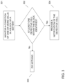
- FIG. 3 illustrates an example method of identifying defective cells within a block of a battery.
- FIG. 4 (A-C) provides an example illustration of how defective cells may be identified in a block of a battery over time.
- batteries are composed of one or more battery blocks that each contains multiple battery cells (e.g., lithium-ion (Li-ion) cell, etc.) assembled in serial and in parallel.
- battery cells e.g., lithium-ion (Li-ion) cell, etc.
- FIG. 1 a conventional battery block containing a plurality of connected cells is illustrated.
- the individual cells within the battery block may wear down at different rates.
- a battery with single or multiple bad cells or blocks may be unable to effectively provide power to a device even if the remaining cells are still in good working condition.
- conventional methods for identifying the defective cell must be conducted manually. More particularly, an individual must test each individual cell in the block to identify the defective one. Such a process may be extremely time-consuming and burdensome, especially if a single block contains many hundreds of connected cells.
- an embodiment provides a method of providing quality indications on the exterior of individual cells within a battery block. Such indications may aid in the identification of defective cells and/or may be useful in the reuse of cells or blocks from dead batteries.
- the exterior of each of the cells within a battery block may be coated with some type of thermochromic material (e.g., heatsensitive temperature gauge, smart inks, etc.). When this material is activated (e.g., from a change in voltage, heat/temperature, impedance, etc. passed a designed threshold), an on-demand persistent and visible state change may occur (i.e., the color of the thermochromic coating may change). This color change may enable a user or device (e.g., a battery management unit, etc.) to quickly identify the defective cell from within a batch of healthy cells.
- a user or device e.g., a battery management unit, etc.
- FIG. 2 depicts a block diagram of another example of information handling device circuits, circuitry or components.
- the example depicted in FIG. 2 may correspond to computing systems such as the THINKPAD series of personal computers sold by Lenovo (US) Inc. of Morrisville, NC, or other devices.
- embodiments may include other features or only some of the features of the example illustrated in FIG. 2 .
- FIG. 2 includes a so-called chipset 210 (a group of integrated circuits, or chips, that work together, chipsets) with an architecture that may vary depending on manufacturer (for example, INTEL, AMD, ARM, etc.).
- INTEL is a registered trademark of Intel Corporation in the United States and other countries.
- AMD is a registered trademark of Advanced Micro Devices, Inc. in the United States and other countries.
- ARM is an unregistered trademark of ARM Holdings plc in the United States and other countries.
- the architecture of the chipset 210 includes a core and memory control group 220 and an I/O controller hub 250 that exchanges information (for example, data, signals, commands, etc.) via a direct management interface (DMI) 242 or a link controller 244 .
- DMI direct management interface
- the DMI 242 is a chip-to-chip interface (sometimes referred to as being a link between a “northbridge” and a “southbridge”).
- the core and memory control group 220 include one or more processors 222 (for example, single or multi-core) and a memory controller hub 226 that exchange information via a front side bus (FSB) 224 ; noting that components of the group 220 may be integrated in a chip that supplants the conventional “northbridge” style architecture.
- processors 222 comprise internal arithmetic units, registers, cache memory, busses, I/O ports, etc., as is well known in the art.
- the memory controller hub 226 interfaces with memory 240 (for example, to provide support for a type of RAM that may be referred to as “system memory” or “memory”).
- the memory controller hub 226 further includes a low voltage differential signaling (LVDS) interface 232 for a display device 292 (for example, a CRT, a flat panel, touch screen, etc.).
- a block 238 includes some technologies that may be supported via the LVDS interface 232 (for example, serial digital video, HDMI/DVI, display port).
- the memory controller hub 226 also includes a PCI-express interface (PCI-E) 234 that may support discrete graphics 236 .
- PCI-E PCI-express interface
- the I/O hub controller 250 includes a SATA interface 251 (for example, for HDDs, SDDs, etc., 280 ), a PCI-E interface 252 (for example, for wireless connections 282 ), a USB interface 253 (for example, for devices 284 such as a digitizer, keyboard, mice, cameras, phones, microphones, storage, other connected devices, etc.), a network interface 254 (for example, LAN), a GPIO interface 255 , a LPC interface 270 (for ASICs 271 , a TPM 272 , a super I/O 273 , a firmware hub 274 , BIOS support 275 as well as various types of memory 276 such as ROM 277 , Flash 278 , and NVRAM 279 ), a power management interface 261 , a clock generator interface 262 , an audio interface 263 (for example, for speakers 294 ), a TCO interface 264 , a system management bus interface 265 , and
- the system upon power on, may be configured to execute boot code 290 for the BIOS 268 , as stored within the SPI Flash 266 , and thereafter processes data under the control of one or more operating systems and application software (for example, stored in system memory 240 ).
- An operating system may be stored in any of a variety of locations and accessed, for example, according to instructions of the BIOS 268 .
- a device may include fewer or more features than shown in the system of FIG. 2 .
- Information handling circuitry may be utilized to help facilitate the identification of the condition of one or more battery cells.
- the circuitry outlined in FIG. 2 may be implemented in a laptop or personal computer or may be circuitry that is embodied in a dedicated device that specifically utilized to identify battery cell condition.
- an embodiment provides a method for identifying defective cells within a battery.
- an embodiment may monitor a condition of one or more cells within a block of a battery.
- the condition of a cell refers to its ability to function properly.
- a cell that functions below a predetermined threshold of operation is considered to be one that is defective.
- the exterior surface of each of the cells may be covered with a thermochromic material (i.e., a temperature-sensitive material that can change color from exposure to heat).
- thermochromic material i.e., a temperature-sensitive material that can change color from exposure to heat.
- thermochromic materials include: thermochromic tape adhered to the exterior surface of the cell or thermochromic paints or dyes that the exterior surface of the cell can be coated with.
- the thermochromic material may be designed to initiate the color-state change at a predetermined threshold based upon one or more aspects of the battery cell.
- the thermochromic material may change color based upon the heat generated from an applied voltage and/or current cycle during an active inspection period, as further described below.
- the design of the thermochromic material material i.e., the chemical composition of the material
- the thermochromic material may dictate the threshold at which such a visible state change occurs.
- the thermochromic material may be designed to undergo a state change at a particular temperature.
- the thermochromic material may be designed to undergo a state change in response to detecting a temperature that is known to be associated with battery overheating.
- the monitoring process may occur during a dedicated active inspection period.
- This period may be a time during which the voltage and/or current of one or more cells is intentionally cycled (i.e., charged and discharged) for a short period of time (e.g., a few seconds, a few minutes, etc.).
- Healthy operational cells may be substantially unaffected during this process. More particularly, the heat emitted from healthy cells during the charge/discharge cycle may not be sufficient (i.e., the heat will not be high enough) to produce the visible state change on the thermochromic coating of the cell. Conversely, defective cells that no longer operate effectively may heat up quicker and to higher temperatures than operational cells (e.g., due to overwork to maintain a charge). The heat emitted from these defective cells may be enough to activate the color change properties of the thermochromic material.
- the monitoring process may be conducted manually (i.e., by a human user) or automatically by a battery management unit (BMU).
- BMU battery management unit
- a human user may manually modulate the voltage and/or current in each cell and then monitor to see if a color change occurs to determine which cells are defective and which cells are operational.
- the BMU may be configured to automatically apply a voltage and/or current modulation to the cells.
- the BMU may be a dedicated cell-condition monitoring device or, alternatively, the BMU may be a component integrated within a larger device.
- the BMU may contain one or more cameras that are capable of capturing images of the cell surface.
- the images of the cells may be taken at predetermined intervals during the active inspection period (e.g., a predetermined time after the voltage and/or current modulation has been applied, etc.) or may be taken in response to predetermined events (e.g., an explicit user command to take a picture of the cell, etc.).
- an embodiment may determine that the condition of at least one cell in the block has fallen below a predetermined threshold. In an embodiment, the determination may be facilitated by identifying that the exterior of one or more cells in the block has undergone a color change event. More particularly, an embodiment may analyze the captured image in step 301 (e.g., using one or more image analysis techniques known in the art, etc.) to determine whether the image contains the presence of a specific color. In this regard, an embodiment may access a ruleset in a database (e.g., stored locally on the device or stored remotely on another device or server, etc.) that designates which color is associated with a defective battery.
- a database e.g., stored locally on the device or stored remotely on another device or server, etc.
- the choice of color for the defective battery may be user-driven and may be based on the characteristics and design of the thermochromic material. Responsive to identifying that the color is present in the image, an embodiment may conclude that at least one cell in the block is defective. An embodiment may further record the identity of the cell (i.e., its position in the cell block) which may later be provided to a user in a notification, as further described below.
- FIG. 4 A-C
- a cell block 41 contains a plurality of operational cells 42 (i.e., unshaded cells) and defective cells 43 (i.e., shaded cells).
- operational cells 42 i.e., unshaded cells
- defective cells 43 i.e., shaded cells.
- the defective cells 43 are easily identifiable to a user or to a device based upon their visible differences from the operational cells 42 .
- an embodiment may, at 303 , take no additional action. Conversely, responsive to determining, at 302 , that the color change event has occurred, an embodiment may, at 304 , provide a notification. In an embodiment, the provision of the notification may occur automatically (i.e., without the receipt of any additional user input).
- the notification may be provided to one or more designated devices.
- the designated devices may be initially established by a manufacturer but may later be changed by a user.
- virtually any device capable of receiving notifications may be designated to receive the notification (e.g., a user's device, an administrator's device, etc.).
- the notification may contain an indication that one or more cells in a battery are defective.
- the notification may specify the number of defective cells in a battery block and/or the locations of the defective cells within the battery block. Additionally or alternatively, the notification may contain the captured image of the battery block. In this situation, the user may be apprised of which cells are defective simply based on a visual inspection of the image (i.e., a user can easily identify which of the cells are different colors than the rest).
- the BMU may further be configured to write additional information onto the exterior surface of the cells.
- the BMU may contain a writing means that can print such information onto the cell.
- the additional information may include: a marking of battery chemistry, a date of cell block formation, a date of last inspection, and a date of defective cell identification.
- an intelligence solution may be incorporated into the BMU firmware where information associated with each cell's temperature is monitored and compared to the expected behavior of the cell based on the applied current and voltage. Utilizing this techniques, defective cells may be identified without ever opening the battery pack.
- an embodiment may monitor, using a battery management unit and during an active inspection period, the condition of cells within a battery block.
- Each of the cells may be coated with a thermochromic material that is designed to change color based upon heat emitted from a battery.
- An embodiment may distinguish defective cells from operational cells by identifying the color changes on the exterior surface of the battery. Responsive to making these distinctions, an embodiment may provide a notification corresponding to the defective cell identification.
- Such techniques may simplify the recycling process of battery cells and may also extend the usability of the battery beyond its originally intended application.
Abstract
Description
Claims (18)
Priority Applications (1)
| Application Number | Priority Date | Filing Date | Title |
|---|---|---|---|
| US17/490,827 US11888129B2 (en) | 2021-09-30 | 2021-09-30 | Battery cell wear indicator |
Applications Claiming Priority (1)
| Application Number | Priority Date | Filing Date | Title |
|---|---|---|---|
| US17/490,827 US11888129B2 (en) | 2021-09-30 | 2021-09-30 | Battery cell wear indicator |
Publications (2)
| Publication Number | Publication Date |
|---|---|
| US20230100428A1 US20230100428A1 (en) | 2023-03-30 |
| US11888129B2 true US11888129B2 (en) | 2024-01-30 |
Family
ID=85705856
Family Applications (1)
| Application Number | Title | Priority Date | Filing Date |
|---|---|---|---|
| US17/490,827 Active 2042-01-21 US11888129B2 (en) | 2021-09-30 | 2021-09-30 | Battery cell wear indicator |
Country Status (1)
| Country | Link |
|---|---|
| US (1) | US11888129B2 (en) |
Citations (3)
| Publication number | Priority date | Publication date | Assignee | Title |
|---|---|---|---|---|
| US20160195437A1 (en) * | 2015-01-07 | 2016-07-07 | The Boeing Company | Systems and methods for monitoring temperatures of batteries |
| US20180337560A1 (en) * | 2013-03-15 | 2018-11-22 | Christopher V. Beckman | System for Monetizing Wireless Power Sharing |
| US20210135473A1 (en) * | 2017-03-07 | 2021-05-06 | Volt Technology Limited | Battery with a voltage regulation device |
-
2021
- 2021-09-30 US US17/490,827 patent/US11888129B2/en active Active
Patent Citations (3)
| Publication number | Priority date | Publication date | Assignee | Title |
|---|---|---|---|---|
| US20180337560A1 (en) * | 2013-03-15 | 2018-11-22 | Christopher V. Beckman | System for Monetizing Wireless Power Sharing |
| US20160195437A1 (en) * | 2015-01-07 | 2016-07-07 | The Boeing Company | Systems and methods for monitoring temperatures of batteries |
| US20210135473A1 (en) * | 2017-03-07 | 2021-05-06 | Volt Technology Limited | Battery with a voltage regulation device |
Also Published As
| Publication number | Publication date |
|---|---|
| US20230100428A1 (en) | 2023-03-30 |
Similar Documents
| Publication | Publication Date | Title |
|---|---|---|
| US10438559B2 (en) | Electronic device supporting USB interface and control method for USB interface | |
| US11031788B2 (en) | Charging control method for battery based on time and electronic device supporting the same | |
| US9952645B2 (en) | Firmware update and power system thereof | |
| US11055238B2 (en) | Electronic device and method for recognizing accessories | |
| US10355415B2 (en) | PCB including connector and grounds with different potentials, and electronic device having the same | |
| CN105144074B (en) | It is stored using the block of hybrid memory device | |
| US20180267586A1 (en) | Charge control method and electronic device based on voltage of battery | |
| US20200203783A1 (en) | Battery swelling detection | |
| US9723408B2 (en) | Electronic device and method of preventing erroneous recognizing inserting connector into earphone jack | |
| US20150033049A1 (en) | Method, device and mobile terminal for information backup | |
| US20180300202A1 (en) | System and Method for Information Handling System Boot Status and Error Data Capture and Analysis | |
| WO2016190573A1 (en) | Electronic device and power managing method thereof | |
| US10705585B2 (en) | Battery charge leakage monitor | |
| US10566813B2 (en) | Method for controlling operation of battery on basis of state thereof, and electronic device for supporting same | |
| US6822424B2 (en) | Trouble recognition of an intelligent battery and the resetting thereof | |
| WO2018111039A1 (en) | Method for charging electronic device, electronic device, and storage medium | |
| US11888129B2 (en) | Battery cell wear indicator | |
| CN105786315A (en) | Time display method and device | |
| US10963359B2 (en) | Battery management unit based runtime monitoring of power consumption | |
| CN110556884B (en) | Charging management method, device, medium and electronic equipment applying method | |
| CN108710037A (en) | OPS condition detection methods, system and equipment | |
| US20220050688A1 (en) | Device state data loading onto rfid chip | |
| US9897661B2 (en) | Automatically determining a number of functioning batteries | |
| US10819122B2 (en) | Systems and methods to use cell balancing resistor(s) of battery pack to reduce charge level of battery cells | |
| US9183722B1 (en) | Adjusting light emitted by a device based on charge or discharge rate of a battery associated with the device |
Legal Events
| Date | Code | Title | Description |
|---|---|---|---|
| AS | Assignment |
Owner name: LENOVO (UNITED STATES) INC., NORTH CAROLINA Free format text: ASSIGNMENT OF ASSIGNORS INTEREST;ASSIGNORS:PETERSEN, JOHN M;YEBKA, BOUZIANE;CUDAK, GARY D;AND OTHERS;REEL/FRAME:057660/0025 Effective date: 20210928 |
|
| FEPP | Fee payment procedure |
Free format text: ENTITY STATUS SET TO UNDISCOUNTED (ORIGINAL EVENT CODE: BIG.); ENTITY STATUS OF PATENT OWNER: LARGE ENTITY |
|
| STPP | Information on status: patent application and granting procedure in general |
Free format text: DOCKETED NEW CASE - READY FOR EXAMINATION |
|
| AS | Assignment |
Owner name: LENOVO (SINGAPORE) PTE. LTD., SINGAPORE Free format text: ASSIGNMENT OF ASSIGNORS INTEREST;ASSIGNOR:LENOVO (UNITED STATES) INC.;REEL/FRAME:059632/0312 Effective date: 20220110 |
|
| STPP | Information on status: patent application and granting procedure in general |
Free format text: NON FINAL ACTION MAILED |
|
| STPP | Information on status: patent application and granting procedure in general |
Free format text: NOTICE OF ALLOWANCE MAILED -- APPLICATION RECEIVED IN OFFICE OF PUBLICATIONS |
|
| STPP | Information on status: patent application and granting procedure in general |
Free format text: PUBLICATIONS -- ISSUE FEE PAYMENT RECEIVED |
|
| STPP | Information on status: patent application and granting procedure in general |
Free format text: PUBLICATIONS -- ISSUE FEE PAYMENT VERIFIED |
|
| STCF | Information on status: patent grant |
Free format text: PATENTED CASE |