EP3593073B1 - Kältegerät - Google Patents
Kältegerät Download PDFInfo
- Publication number
- EP3593073B1 EP3593073B1 EP18763435.7A EP18763435A EP3593073B1 EP 3593073 B1 EP3593073 B1 EP 3593073B1 EP 18763435 A EP18763435 A EP 18763435A EP 3593073 B1 EP3593073 B1 EP 3593073B1
- Authority
- EP
- European Patent Office
- Prior art keywords
- cabinet
- closed
- box
- face
- insulated cabinet
- Prior art date
- Legal status (The legal status is an assumption and is not a legal conclusion. Google has not performed a legal analysis and makes no representation as to the accuracy of the status listed.)
- Active
Links
Images



Classifications
-
- F—MECHANICAL ENGINEERING; LIGHTING; HEATING; WEAPONS; BLASTING
- F25—REFRIGERATION OR COOLING; COMBINED HEATING AND REFRIGERATION SYSTEMS; HEAT PUMP SYSTEMS; MANUFACTURE OR STORAGE OF ICE; LIQUEFACTION SOLIDIFICATION OF GASES
- F25D—REFRIGERATORS; COLD ROOMS; ICE-BOXES; COOLING OR FREEZING APPARATUS NOT OTHERWISE PROVIDED FOR
- F25D23/00—General constructional features
- F25D23/06—Walls
- F25D23/062—Walls defining a cabinet
-
- F—MECHANICAL ENGINEERING; LIGHTING; HEATING; WEAPONS; BLASTING
- F25—REFRIGERATION OR COOLING; COMBINED HEATING AND REFRIGERATION SYSTEMS; HEAT PUMP SYSTEMS; MANUFACTURE OR STORAGE OF ICE; LIQUEFACTION SOLIDIFICATION OF GASES
- F25D—REFRIGERATORS; COLD ROOMS; ICE-BOXES; COOLING OR FREEZING APPARATUS NOT OTHERWISE PROVIDED FOR
- F25D23/00—General constructional features
- F25D23/006—General constructional features for mounting refrigerating machinery components
-
- F—MECHANICAL ENGINEERING; LIGHTING; HEATING; WEAPONS; BLASTING
- F25—REFRIGERATION OR COOLING; COMBINED HEATING AND REFRIGERATION SYSTEMS; HEAT PUMP SYSTEMS; MANUFACTURE OR STORAGE OF ICE; LIQUEFACTION SOLIDIFICATION OF GASES
- F25D—REFRIGERATORS; COLD ROOMS; ICE-BOXES; COOLING OR FREEZING APPARATUS NOT OTHERWISE PROVIDED FOR
- F25D23/00—General constructional features
- F25D23/06—Walls
-
- F—MECHANICAL ENGINEERING; LIGHTING; HEATING; WEAPONS; BLASTING
- F25—REFRIGERATION OR COOLING; COMBINED HEATING AND REFRIGERATION SYSTEMS; HEAT PUMP SYSTEMS; MANUFACTURE OR STORAGE OF ICE; LIQUEFACTION SOLIDIFICATION OF GASES
- F25D—REFRIGERATORS; COLD ROOMS; ICE-BOXES; COOLING OR FREEZING APPARATUS NOT OTHERWISE PROVIDED FOR
- F25D23/00—General constructional features
- F25D23/06—Walls
- F25D23/065—Details
- F25D23/066—Liners
-
- F—MECHANICAL ENGINEERING; LIGHTING; HEATING; WEAPONS; BLASTING
- F25—REFRIGERATION OR COOLING; COMBINED HEATING AND REFRIGERATION SYSTEMS; HEAT PUMP SYSTEMS; MANUFACTURE OR STORAGE OF ICE; LIQUEFACTION SOLIDIFICATION OF GASES
- F25D—REFRIGERATORS; COLD ROOMS; ICE-BOXES; COOLING OR FREEZING APPARATUS NOT OTHERWISE PROVIDED FOR
- F25D2201/00—Insulation
- F25D2201/10—Insulation with respect to heat
- F25D2201/12—Insulation with respect to heat using an insulating packing material
Definitions
- the present invention relates to a refrigeration appliance.
- the sheet steel outer panels have become thinner and the welding of the corners of forward facing flanges has been eliminated.
- the modern refrigeration appliance cabinet relies on the sandwich construction of the outer wrapper, foam and inner liner for its structural integrity. This may be satisfactory for short-term loads, but the long-term loading from the door and food placed in shelving on an inner side of the door will force the cabinet structure to creep due to shear deflection of the foam, allowing the door to drop or droop relative to the cabinet.
- This door drop is usually countered by adding structural steel to the perimeter of the cabinet, behind the forward-facing flange.
- the structural steel has the disadvantage that it presents a thermal heat flow path that allows heat leakage into the cabinet, reducing operational efficiency.
- US20090284116A1 discloses a refrigerator or freezer having a reinforcement frame about its open face.
- EP2789953A1 discloses a refrigerator having a top plate which is stepped-down to provide a machine room for housing a compressor.
- US2835405A discloses a refrigerated cabinet structure in which side walls of a refrigerating equipment space, at the base of the cabinet, are formed by an extension of the sheet metal side walls of the cabinet. The features of the preamble of claim 1 are known from US 4 580 852 A .
- the invention consists in a refrigeration appliance comprising:
- the insulated cabinet comprises an inner liner and an insulating material between the outer skin and inner liner.
- the torsionally stiff structure forms a plinth for the insulated cabinet.
- the torsionally stiff structure comprises a 3-dimensional structure surrounding a central volume.
- the torsionally stiff structure comprises six sides wherein each side is either closed so that access to the central volume via that side is prevented, or open so that access to the central volume via that side is possible.
- the box has one open side and the box is fixed to the insulated cabinet so that an open side of the box is closed by a closed face of the insulated cabinet, the closed face of the insulated cabinet and the box forming the torsionally stiff structure.
- the box has an open top side and is attached to the bottom closed face of the insulated cabinet so that the open top side of the box is closed by the bottom closed face of the insulated cabinet, the bottom closed face of the insulated cabinet and the box forming the torsionally stiff structure.
- the sheet metal box has a front side, and comprises at least one gusset at a substantially open front side, each gusset attached between adjacent sides of the box.
- the sheet metal box has closed sheet metal vertical sides, a closed sheet metal bottom side and a closed sheet metal rear side.
- the sheet metal of the box has a thickness greater than a thickness of the wrapper of the insulated cabinet.
- the thickness of the sheet metal of the box is at least twice the thickness of the wrapper of the insulated cabinet.
- pivotally and rotationally includes both a purely rotational relative movement about an axis, as well as a combination of rotation about an axis and translation of that axis (an example of the combined rotation and translation being provided by a door connected to a cabinet by an articulated hinge).
- torsionally stiff and torsionally weak are relative terms meaning, respectively, having the ability to substantially resist twisting by a torque resulting from an applied force in an operational range normally expected to be encountered by a refrigerator cabinet, and not having the ability to substantially resist that torque.
- cuboid is intended to mean, unless the context indicates otherwise, a 3-dimensional structure such as a rectangular prism, comprising six main sides or faces (for example a rectangular cuboid or a square cuboid).
- One or more main sides may be open faces, for example an open framework (a space frame) or closed faces of the cuboid.
- This invention may also broadly be said to consist in the parts, elements and features referred to or indicated in the specification of the application, individually or collectively, and any or all combinations of any two or more said parts, elements or features, and where specific integers are mentioned herein which have known equivalents in the art to which this invention relates, such known equivalents are deemed to be incorporated herein as if individually set forth.
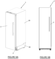
- a refrigeration appliance 1 according to some embodiments of the present invention is illustrated in Figures 6A and 6B .
- the refrigeration appliance comprises an insulated cabinet 20 with an open front face, and a door 2 for selectively opening and closing the front face.
- the overall height of the refrigeration appliance may, for example, be around 84 inches (around 213 cm) which is relatively tall for modern refrigeration appliances.
- the door 2 is openably operatively connected (such as via a rotational or pivotal connection) to the cabinet 20 by hinges (such as articulated hinges, one of which is visible at the top edge of the door in Figure 6A ) at one side thereof to selectively close the open face of the cabinet.
- the door may have shelves on an inner side for supporting food or bottles.
- the refrigeration appliance shown in Figures 6A and 6B is of the "built-in" variety and so its outer front face is part of a door panel removably and adjustably attached to the actual hinged insulated cabinet door below.
- a mass m of the door 2 (and any food supported on shelves on the inner side of the door) creates a moment M at a side of a torsionally weak insulated refrigeration appliance cabinet 20 to which the door is pivotally/rotationally connected.
- the moment M forces the rectangular front open face of the refrigeration appliance cabinet (and each of the other faces) into a substantially parallelogram shape, when viewed from the front of the cabinet.
- the refrigeration appliance cabinet 20 comprises five closed faces; the left and right sides, top, bottom and back faces.
- closed it is meant that the side or face does not allow a user access therethrough for adding/removing articles to/from a volume enclosed by the cabinet whereas an "open” side or face allows a user access therethrough to the enclosed volume.
- Cabinet 20 is, at least in part, be formed by folding sheet metal (such as painted steel or stainless steel) to form at least a part of the cabinet wrapper.
- sheet metal such as painted steel or stainless steel
- the two longer, vertical side panels/closed faces and the top panel/closed face may be formed by folding a single sheet of metal into a substantially upside-down "U"-shape and the back and bottom panels/closed faces may be attached thereto by, for example riveting or welding.
- the moment M produced by the door's weight will cause the cabinet to deflect as shown in Figures 1A and 1B , with each of the edges retaining their original length.
- each closed face of the cabinet twists. Being formed from a material such as sheet steel, each closed face is very stiff in the planar direction of the face, however each face can bend or twist out of its plane.
- the shape of a deformed cabinet and face resulting from moment M acting on the torsionally weak cabinet may be reproduced by holding still one of the top or bottom faces of a torsionally weak rectangular prism (such as a cardboard box) while twisting the other of the top or bottom face of the box about an axis through the top and bottom faces.
- the present invention seeks to actively eliminate the twist in one face of the cabinet. Actively eliminating twist in one face of the cabinet passively prevents or obstructs all of the other cabinet faces twisting and therefore prevents the entire cabinet from deforming significantly.
- deformation of the refrigeration appliance cabinet, and therefore door drop relative to the cabinet is eliminated or reduced to an acceptable level by adding a torsionally rigid or stiff structure to one of the five closed faces of the cabinet. That is, a structure is added (i.e., attached, coupled, fixed or connected) to the cabinet so that the torsional rigidity/stiffness of the resulting assembly (i.e., cabinet+structure) is greater than that of the cabinet alone.
- the cabinet comprises an outer skin or wrapper, inner liner, and an insulating material in between.
- the sheet steel forming the wrapper may be for example steel sheet with a thickness of less than 1 mm, preferably between about 0.4 mm and 0.6 mm, most preferably about 0.5 mm.
- the cabinet is a torsionally weak structure, due at least in part to the relatively thin section of the sheet material.
- the folded corners or edges between the side and top panels present relatively rigid edges between the top and sides of the cabinet. Connections between the "U"-shaped sheet and the base and back panels are also rigid, for example by riveting or by other connecting means known in the art.
- the front of the cabinet comprises an open face to provide access to the inside of the cabinet via a door of the refrigeration appliance.
- Torsionally weak in relation to the cabinet, means that in response to an appropriately-directed force or moment having a magnitude within an expected operational loading range, the closed faces of the cabinet can relatively easily twist out of plane.
- the cabinet twists and the shape of the open front face of the cabinet deforms from a rectangle to a parallelogram (when viewed from in front of the cabinet) which is no longer substantially planar. Deformation of the cabinet may prevent the door from sealing the cooling compartments within the cabinet when in a closed position.
- a torsionally stiff structure is provided to one of the five closed faces of the cabinet.
- a torsionally stiff structure may be provided to the top face or the bottom face of the cabinet.
- a thin torsionally stiff structure may be provided to a left or right side face, or a rearface of the cabinet.
- a torsionally stiff structure is applied to the bottom or top closed face of the cabinet since typically within a building space (e.g., in a kitchen) in which a refrigeration appliance is located there is sufficient vertical height to accept a torsionally stiff structure above or below the cabinet.
- the torsionally stiff structure may be an auxiliary structure, attached to the cabinet subsequent to the cabinet's construction, or it may be built into the cabinet structure during the cabinet's construction. At least a part of the torsionally stiff structure may also be formed integrally with at least part of the cabinet (for example, as a folded box formed from the same sheet of steel as one or more of the panels of the cabinet) or could be formed from components completely distinct and separate from components used in the construction of the cabinet.
- the torsionally stiff structure could be a combination of an auxiliary structure and an existing part (such as a side or face) of the cabinet.
- a torsionally stiff structure is a structure that does not significantly twist under normal operational loading. That is, when one end or face of the structure is held firmly, the structure is able to resist rotation of an opposite end of the structure about an axis through both ends (see Figure 1A ).
- a thick solid plate may be sufficiently rigid to act as a torsionally stiff structure, for example a thick steel plate having a thickness of more than 5 mm.
- the torsionally stiff structure could be a continuous, solid thick plate or could be a frame (e.g. a 2-dimensional frame like a picture frame) cut from a solid thick plate.
- a thick plate or frame may be less preferred as it may provide a thermal heat flow path to the inside of the refrigeration appliance (if used on the inside of the wrapper such that it displaces an amount of insulation) and is an inefficient use of material.
- the torsionally stiff structure comprises a 3-dimensional framework.
- the torsionally stiff structure comprises a hollow cuboid or rectangular prism, e.g. a cuboid framework or a hollow cuboid with one or more closed faces.
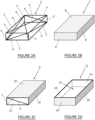
- Figure 2A illustrates a torsionally stiff structure comprising a cuboid space frame 4, the space frame 4 comprising a rigid member or strut 5 along or forming each edge of the frame and rigid diagonal members 6 across each open face or side of the space frame between diagonally opposed corners.
- the diagonal members 6 may be oppositely arranged in opposing sides of the framework 4.
- each side of the space frame may comprise a diagonal member between adjacent perimeter edge members.
- the space frame 4 may comprise a diagonal member across five sides of the framework, and with a single side without a diagonal memberto be attached to a closed side of the cabinet.
- the space frame may be without diagonal members, for example in a welded construction comprising edge members 5 that provide sufficient corner rigidity without diagonal members.
- Figure 2B illustrates a torsionally stiff structure comprising a sheet metal box 7 or cuboid. All six main sides 8 of the box comprise sheet metal, e.g. a sheet metal panel such as sheet steel.
- the thickness of the sheet metal-forming closed faces of the box is sufficiently thick to prevent twisting of the box.
- the thickness of the outer skin of the torsionally weak cabinet is about 0.5 mm
- the thickness of the sheet metal box formed from the same material (such as sheet steel) as the cabinet and providing a torsionally stiff structure may be between about 0.5 mm to about 1.5 mm.
- the thickness of the sheet metal forming the box may, purely as an example, be at least about 1.5 times the thickness of the outer skin of the refrigeration appliance cabinet. Some faces could be thinner than others.
- Figure 2C illustrates a torsionally stiff structure comprising a box or cuboid 9 having five sheet metal, closed faces 10 and a sixth face or side 11 (the front side in the drawing figure) comprising a framework.
- the framework comprises four rigid perimeter or edge members 5 and a rigid diagonal member 6 in the plane of the open face to stiffen the open face.
- Other combinations which are not comprised by the invention of closed and open faces may be provided, for example a structure comprising four sheet metal, closed faces 10 and two opposed, open framework faces 11, each framework face comprising four rigid perimeter members 5 and one or more rigid diagonal member(s) 6 for stiffening an open face or faces, for example as described with reference to Figure 2A .
- open faces could be stiffened by corner gussets, for example.
- Figure 2D illustrates a box or cuboid 12 comprising five sheet metal closed faces 10 and a sixth, open face 13.
- a closed face of the torsionally weak cabinet closes or provides the sixth face of the torsionally stiff structure.
- the torsionally stiff structure comprises a cuboid sized to accommodate components of a refrigeration system of the refrigeration appliance, for example a compressor and condenser with pipework connecting to at least one evaporator for cooling at least one compartment within the cabinet.
- a refrigeration system of the refrigeration appliance for example a compressor and condenser with pipework connecting to at least one evaporator for cooling at least one compartment within the cabinet.
- the structures illustrated in Figures 2A to 2D may be formed to encompass a sufficiently large volume to beneficially accommodate such a refrigeration system, in addition to preventing or reducing twisting of the cabinet.
- Figures 3A and 3B show two embodiments each comprising a torsionally weak cabinet 20 and a torsionally stiff structure 30 located at and rigidly secured to a base or bottom side of the torsionally weak cabinet 20.
- the illustrated cabinet 20 may be the outer skin for an insulated cabinet comprising the outer skin, an inner liner and insulation between the outer skin and inner liner, the cabinet having five closed faces and an open front face.
- the torsionally stiff structures 30 in Figures 3A and 3B are each sized to house components of a refrigeration system for the refrigeration appliance. As the torsionally stiff structure is located at the bottom of the cabinet the torsionally stiff structure beneficially acts as a plinth for the cabinet to house refrigeration components below the cabinet and raise the cabinet (and its enclosed compartments) slightly to ease access by a user.
- the torsionally stiff structure 30 includes a cuboid or box 31.
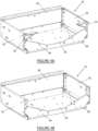
- the box 31 shown together with the cabinet 20 in Figures 3A and 3B is shown separated from the cabinet 20 in Figures 4A and 4B .
- the box 31 comprises four main closed faces; left and right faces 32, a bottom face 33 and a rear face 34.
- a front side is open and the box is stiffened by corner gussets 35, 36 provided at or near to the open front face of the box 31.
- the open front face allows for access to the refrigeration system components, for example for maintenance and/or for air flow.
- the open front face may be covered by a grill or grate, e.g. grate 3 shown in Figure 6A .
- the door 2 (or at least the outer panel attached to the actual door) of the refrigeration appliance may cover the front face of the box 31 when in a closed position, as shown in Figure 6A .
- Each gusset is attached to two adjacent sides of the box, or to a side of the box and a face of the cabinet 20.
- each gusset 36 is attached to a vertical side 32 and a horizontal side 33 of the structure while each gusset 35 is attached to a vertical side 32 and the base panel 23 of the cabinet 20.
- the box 31 is stiffened by four gussets 35, 36.
- Two gussets 36 are attached to a vertical side 32 and to the bottom side 33 of the box, and two gussets 35 attached to vertical side 32 and bottom face 23 of the cabinet 20, the four gussets 35, 36 positioned at each corner of the open face so that a considerable central opening remains in that face.
- the box is stiffened by two gussets 36, each attached to a vertical side 32 of the box and the bottom 33 of the box 31.
- the gussets may be formed from the same sheet steel material (and thickness) as the material used to form box 31. In some embodiment two gussets or four gussets may be integrally formed, e.g. cut and/or folded to form a monolithic component from a single blank or sheet material.
- the gussets may be substantially planar and attachment to a panel may be via a flange formed on that panel, perpendicular to the panel, such as gusset 36.
- the gussets could be formed with a perpendicular flange at an edge or edges thereof adapted to be fastened directly to the face of an adjacent panel, such as gusset 35.
- the top side of the box 31 is open.
- the open top side of the box is closed by attaching the box to the base or closed bottom face 23 of the cabinet 20, for example as explained above with reference to Figure 2D .
- the box 31 is rigidly fixed to the bottom side 23 of the cabinet.
- the bottom panel 23 of the cabinet closes the top side of the box 31 to create a torsionally stiff structure 30 comprising five closed main sides (the top 23, bottom 33, rear 34 and left and right sides 32) and an open front with two or four gussets at the open front.
- FIGS 5A and 5B show the torsionally stiff structure 30 comprising the box 31 and the bottom panel 23 of the cabinet cut away from the vertical sides 22 of the cabinet 20.
- the cabinet bottom 23, which is also the top side of the torsionally rigid structure 30, is prevented from twisting because it is an integral part of a torsionally stiff assembly comprising the other five sides of the box 31, which thereby prevents the entire cabinet 20 from twisting.
- the box 31 itself having an open top face, is not substantially torsionally stiff, but when rigidly fixed to base 23 the torsionally stiff structure 30 results.
- the box could also include a closed upper face, thereby increasing the torsional stiffness of the box and making the box itself torsionally stiff.
- the closed upper face of the torsionally stiff box could then be rigidly fixed to the cabinet bottom face 23 to produce a refrigeration cabinet assembly having a torsional stiffness greater than the torsional stiffness of the cabinet on its own.
- the cabinet must be reliably and strongly attached to the torsionally stiff structure without allowing relative movement or flexing therebetween, otherwise the cabinet will be able to twist.
- the torsionally stiff structure or box is rigidly fixed to the outer skin of the cabinet by welding, riveting, screws or other suitable fasteners, or by any other rigid fixing means know in the art that will substantially avoid any relative sliding movement between adjacent faces of the cabinet and torsionally stiff structure.
- the left and right sides 32, bottom 33 and rear 34 sides of box 31 may be folded from sheet metal, or may be separate panels fixed together, or any combination of folding and fixing.
- the thickness of the sheet metal may be thicker than the thickness of the outer skin of the cabinet.
- the gussets may be formed from sheet metal and may have the same thickness as the metal forming the closed sides of the box or may be formed from an alternative material having adequate stiffness.
- the present invention utilises a torsionally stiff structure fixed to or comprising one face of the refrigeration appliance cabinet to allow cost to be removed from the cabinet (auxiliary structural components in the cabinet such as reinforcing steel around the door opening are not required) which also improves the thermal insulation of the cabinet (by enabling insulating foam to replace the volume previously occupied by the removed heat-conducting structural components), and reduces material usage.
- the torsionally stiff structure may be attached to or include any one (or more) of the sides of the cabinet.
- the torsional resistance of the side of the cabinet with the torsionally stiff structure stops or restrains that side of the cabinet from twisting, which means that none of the sides of the cabinet can twist. Because the cabinet cannot twist, the door attached to a front open face of the cabinet cannot droop so that the door stays in alignment with the open front face of the cabinet, and the door seal stays engaged with the peripheral front flange of the cabinet door opening when the door is in a closed position.
Landscapes
- Engineering & Computer Science (AREA)
- Chemical & Material Sciences (AREA)
- Combustion & Propulsion (AREA)
- Physics & Mathematics (AREA)
- Mechanical Engineering (AREA)
- Thermal Sciences (AREA)
- General Engineering & Computer Science (AREA)
- Refrigerator Housings (AREA)
Claims (11)
- Kältegerät (1) umfassend:eine Anordnung, die einen Isolierschrank (20) umfasst, der fünf geschlossene Flächen und eine offene Fläche umfasst, die Zugang zum Inneren des Schranks bietet,ein Kühlsystem undeine Tür (2), die betriebsmäßig drehbar mit dem Isolierschrank (20) verbunden ist, um die offene Fläche des Isolierschranks selektiv zu öffnen oder zu schließen,wobei der Isolierschrank eine aus Blech geformte Hülle umfasst, wobei der Schrank mindestens teilweise durch Falten von Blech geformt ist, um mindestens einen Teil der Hülle zu bilden, wobei die fünf geschlossenen Flächen starr miteinander verbunden sind oder im Falle des Faltensentlang ihrer zusammentreffenden Kanten durchgehend sind, um mindestens einen Teil der Hülle zu bilden,dadurch gekennzeichnet, dassdie Anordnung auch eine verwindungssteife Struktur (30) einschließt, die einen Blechkasten (31) umfasst, der das Kühlsystem oder die Kühlsystemkomponenten aufnimmt, beispielsweise mindestens einen Kompressor, der an einer geschlossenen unteren Fläche oder einer geschlossenen oberen Fläche der Hülle befestigt ist oder diese umfasst, unddie verwindungssteife Struktur eine Verdrehung der geschlossenen Schrankfläche, an der sie angebracht ist oder die sie einschließt, verhindert oder begrenzt und dadurch die Verwindungssteifigkeit der Anordnung wesentlich über die des Isolierschranks allein hinaus erhöht, so dass der Isolierschrank eine größere Widerstandsfähigkeit gegen Verdrehen aufweist.
- Gerät nach Anspruch 1, wobei der Isolierschrank (20) eine Innenauskleidung und ein Isoliermaterial zwischen der Hülle und der Innenauskleidung umfasst.
- Gerät nach Anspruch 1 oder 2, wobei die verwindungssteife Struktur (30) einen Sockel für den Isolierschrank (20) bildet.
- Gerät nach einem der vorstehenden Ansprüche, wobei die verwindungssteife Struktur eine dreidimensionale Struktur umfasst, die ein zentrales Volumen umgibt.
- Gerät nach einem der vorstehenden Ansprüche, wobei die verwindungssteife Struktur (30) eine dreidimensionale Struktur umfasst, die ein zentrales Volumen umgibt, wobei die verwindungssteife Struktur weiter sechs Seiten (23, 32, 33, 34) umfasst, wobei jede Seite entweder geschlossen ist, so dass der Zugang zum zentralen Volumen über diese Seite verhindert wird, oder offen ist, so dass der Zugang zum zentralen Volumen über diese Seite möglich ist.
- Gerät nach einem der vorstehenden Ansprüche, wobei der Kasten weiter mindestens eine offene Seite umfasst und der Kasten (31) so an dem Isolierschrank (20) befestigt ist, dass eine offene Seite des Kastens durch eine geschlossene Fläche (23) des Isolierschranks verschlossen wird, wobei die geschlossene Fläche des Isolierschranks und der Kasten die verwindungssteife Struktur (30) bilden.
- Gerät nach einem der vorstehenden Ansprüche, wobei der Kasten (31) eine offene Oberseite aufweist und an der unteren geschlossenen Fläche (23) des Isolierschranks (20) angebracht ist, so dass die offene Oberseite des Kastens durch die untere geschlossene Fläche des Isolierschranks verschlossen wird, wobei die untere geschlossene Fläche des Isolierschranks und der Kasten die verwindungssteife Struktur (30) bilden.
- Gerät nach einem der vorstehenden Ansprüche, wobei der Blechkasten (31) eine im Wesentlichen offene Vorderseite aufweist und weiter mindestens eine Verstärkung (35, 36) an der Vorderseite umfasst, wobei jede Verstärkung zwischen benachbarten Seiten (32, 33, 23) des Kastens angebracht ist.
- Gerät nach einem der vorstehenden Ansprüche, wobei der Blechkasten (31) geschlossene vertikale Blechseiten (32), eine geschlossene Blechunterseite (33) und eine geschlossene Blechrückseite (34) aufweist.
- Gerät nach einem der vorstehenden Ansprüche, wobei das Blech des Kastens (31) eine größere Dicke aufweist als eine Dicke der Hülle des Isolierschranks (20).
- Gerät nach Anspruch 10, wobei die Dicke des Blechs des Kastens (31) mindestens doppelt so groß ist wie die Dicke der Hülle des Isolierschranks (20).
Applications Claiming Priority (2)
| Application Number | Priority Date | Filing Date | Title |
|---|---|---|---|
| NZ72991417 | 2017-03-09 | ||
| PCT/NZ2018/050028 WO2018164591A1 (en) | 2017-03-09 | 2018-03-09 | Refrigeration appliance cabinet |
Publications (3)
| Publication Number | Publication Date |
|---|---|
| EP3593073A1 EP3593073A1 (de) | 2020-01-15 |
| EP3593073A4 EP3593073A4 (de) | 2020-12-30 |
| EP3593073B1 true EP3593073B1 (de) | 2024-12-11 |
Family
ID=63449093
Family Applications (1)
| Application Number | Title | Priority Date | Filing Date |
|---|---|---|---|
| EP18763435.7A Active EP3593073B1 (de) | 2017-03-09 | 2018-03-09 | Kältegerät |
Country Status (4)
| Country | Link |
|---|---|
| US (1) | US11168935B2 (de) |
| EP (1) | EP3593073B1 (de) |
| CN (1) | CN110537063B (de) |
| WO (1) | WO2018164591A1 (de) |
Families Citing this family (6)
| Publication number | Priority date | Publication date | Assignee | Title |
|---|---|---|---|---|
| EP3850285B1 (de) * | 2018-09-12 | 2025-02-19 | Fisher & Paykel Appliances Limited | Kältegerätevorrichtung |
| US11248979B2 (en) * | 2019-09-25 | 2022-02-15 | Whirlpool Corporation | Feature in vacuum insulated structure to allow pressure monitoring |
| TR202007983A2 (tr) * | 2020-05-22 | 2021-12-21 | Bsh Ev Aletleri San Ve Tic As | Yuva bağlanti düzeni̇ne sahi̇p bi̇r ev ci̇hazi |
| US11460235B1 (en) | 2021-04-01 | 2022-10-04 | Whirlpool Corporation | Support assembly for an insulated structure |
| KR20240001590A (ko) * | 2022-06-27 | 2024-01-03 | 엘지전자 주식회사 | 냉장고 |
| US20250180278A1 (en) * | 2023-11-30 | 2025-06-05 | Whirlpool Corporation | Refrigerator with a vacuum-insulated structure supported by a structural support with a baseplate welded to the vacuum-insulated structure |
Citations (2)
| Publication number | Priority date | Publication date | Assignee | Title |
|---|---|---|---|---|
| US3948410A (en) * | 1974-08-12 | 1976-04-06 | White Consolidated Industries, Inc. | Refrigerator cabinet |
| US4082825A (en) * | 1973-06-27 | 1978-04-04 | Franklin Manufacturing Company | Method of constructing a refrigeration cabinet |
Family Cites Families (15)
| Publication number | Priority date | Publication date | Assignee | Title |
|---|---|---|---|---|
| GB742011A (en) | 1953-04-28 | 1955-12-14 | Westinghouse Electric Int Co | Improvements in or relating to unitary thermally insulating members |
| US2835405A (en) * | 1954-10-18 | 1958-05-20 | Metalcraft Mfg & Sales Corp | Refrigerated cabinet structure |
| US3276222A (en) * | 1965-08-23 | 1966-10-04 | Gen Motors Corp | Means for improving mobility of a refrigerator |
| US3462966A (en) * | 1967-12-05 | 1969-08-26 | Beverage Air Co | Condensation removing means for refrigerated cabinets |
| KR890001328B1 (ko) * | 1983-01-28 | 1989-04-29 | 산요덴끼 가부시기가이샤 | 냉장고등의 캐비넷 |
| US4580852A (en) * | 1983-12-29 | 1986-04-08 | Inglis Limited | Refrigerator cabinet assembly |
| CA1335938C (en) | 1988-01-14 | 1995-06-20 | Thomas Edward Jenkins | Four-point support system for appliances, particularly refrigerators |
| KR970002650B1 (ko) * | 1988-07-08 | 1997-03-07 | 산덴 가부시기가이샤 | 냉동 및 냉장 유니트 |
| US6082131A (en) * | 1998-10-20 | 2000-07-04 | Hoshizaki Denki Co., Ltd. | Refrigerator |
| JP2005164093A (ja) * | 2003-12-01 | 2005-06-23 | Jamco Corp | エアチラー装置 |
| DE10360908A1 (de) * | 2003-12-23 | 2005-07-21 | BSH Bosch und Siemens Hausgeräte GmbH | Einbau-Kältegerät |
| DE102005057150A1 (de) * | 2005-11-30 | 2007-06-06 | BSH Bosch und Siemens Hausgeräte GmbH | Kühl- bzw. Gefrierschrank mit Verstärkungsrahmen |
| JP6104503B2 (ja) | 2011-12-07 | 2017-03-29 | 東芝ライフスタイル株式会社 | 冷蔵庫の製造方法 |
| EP3850285B1 (de) * | 2018-09-12 | 2025-02-19 | Fisher & Paykel Appliances Limited | Kältegerätevorrichtung |
| KR102290768B1 (ko) * | 2018-11-01 | 2021-08-18 | 엘지전자 주식회사 | 냉장고 |
-
2018
- 2018-03-09 EP EP18763435.7A patent/EP3593073B1/de active Active
- 2018-03-09 US US16/492,523 patent/US11168935B2/en active Active
- 2018-03-09 WO PCT/NZ2018/050028 patent/WO2018164591A1/en not_active Ceased
- 2018-03-09 CN CN201880021465.1A patent/CN110537063B/zh active Active
Patent Citations (2)
| Publication number | Priority date | Publication date | Assignee | Title |
|---|---|---|---|---|
| US4082825A (en) * | 1973-06-27 | 1978-04-04 | Franklin Manufacturing Company | Method of constructing a refrigeration cabinet |
| US3948410A (en) * | 1974-08-12 | 1976-04-06 | White Consolidated Industries, Inc. | Refrigerator cabinet |
Also Published As
| Publication number | Publication date |
|---|---|
| EP3593073A4 (de) | 2020-12-30 |
| EP3593073A1 (de) | 2020-01-15 |
| CN110537063B (zh) | 2022-04-15 |
| WO2018164591A1 (en) | 2018-09-13 |
| US20210140703A1 (en) | 2021-05-13 |
| US11168935B2 (en) | 2021-11-09 |
| CN110537063A (zh) | 2019-12-03 |
Similar Documents
| Publication | Publication Date | Title |
|---|---|---|
| US11168935B2 (en) | Refrigeration appliance cabinet | |
| EP3232144B1 (de) | Kühlschrank | |
| US6019447A (en) | Refrigerator with varying width fresh food and freezer compartments | |
| CA2350419C (en) | Thermal and reinforced refrigerator door | |
| EP1624263A2 (de) | Geformte Kühlschranktür | |
| US9726423B1 (en) | Sliding shelf assembly for a refrigerator appliance | |
| US7726756B2 (en) | Refrigerator with varying width compartments and uniform width doors | |
| US4714304A (en) | Built-in refrigerator cabinet | |
| US5908229A (en) | Outer shell of refrigerator cabinet | |
| JP6038446B2 (ja) | 断熱キャビネット | |
| US12281842B2 (en) | Refrigeration appliance cabinet | |
| CN102317722A (zh) | 冰箱 | |
| CN113544449B (zh) | 具有铰接中梁和阻尼组件的电器 | |
| US6926379B1 (en) | Door brace for a refrigerator cabinet assembly having varying width compartment doors | |
| US7410229B2 (en) | Refrigerator with bowed mullion | |
| JP6832809B2 (ja) | 冷蔵庫 | |
| WO1998004876A1 (en) | Cabinet kit for refrigerator and/or freezer | |
| EP3327381B1 (de) | Haushaltsgerätetür | |
| JP2967181B2 (ja) | 低温貯蔵庫 | |
| US12611051B2 (en) | Door panel for a merchandiser | |
| US20250237099A1 (en) | Cooling device having a hinge box embodiment | |
| US12460857B2 (en) | Refrigerator | |
| US20220099360A1 (en) | Refrigeration device with reinforced housing | |
| CA2492359A1 (en) | Refrigerator with bowed mullion | |
| JPH09318237A (ja) | 貯蔵庫および貯蔵庫の断熱箱体 |
Legal Events
| Date | Code | Title | Description |
|---|---|---|---|
| STAA | Information on the status of an ep patent application or granted ep patent |
Free format text: STATUS: THE INTERNATIONAL PUBLICATION HAS BEEN MADE |
|
| PUAI | Public reference made under article 153(3) epc to a published international application that has entered the european phase |
Free format text: ORIGINAL CODE: 0009012 |
|
| STAA | Information on the status of an ep patent application or granted ep patent |
Free format text: STATUS: REQUEST FOR EXAMINATION WAS MADE |
|
| 17P | Request for examination filed |
Effective date: 20191007 |
|
| AK | Designated contracting states |
Kind code of ref document: A1 Designated state(s): AL AT BE BG CH CY CZ DE DK EE ES FI FR GB GR HR HU IE IS IT LI LT LU LV MC MK MT NL NO PL PT RO RS SE SI SK SM TR |
|
| AX | Request for extension of the european patent |
Extension state: BA ME |
|
| DAV | Request for validation of the european patent (deleted) | ||
| DAX | Request for extension of the european patent (deleted) | ||
| RIN1 | Information on inventor provided before grant (corrected) |
Inventor name: WONG, RICHARD Inventor name: HOU, YUNCHAO Inventor name: MCGILL, IAN CAMPBELL Inventor name: FOSTER, KENNETH WILLIAM |
|
| A4 | Supplementary search report drawn up and despatched |
Effective date: 20201127 |
|
| RIC1 | Information provided on ipc code assigned before grant |
Ipc: F25D 23/00 20060101ALI20201123BHEP Ipc: F25D 11/00 20060101ALI20201123BHEP Ipc: F25D 23/06 20060101AFI20201123BHEP |
|
| STAA | Information on the status of an ep patent application or granted ep patent |
Free format text: STATUS: EXAMINATION IS IN PROGRESS |
|
| 17Q | First examination report despatched |
Effective date: 20210907 |
|
| GRAP | Despatch of communication of intention to grant a patent |
Free format text: ORIGINAL CODE: EPIDOSNIGR1 |
|
| STAA | Information on the status of an ep patent application or granted ep patent |
Free format text: STATUS: GRANT OF PATENT IS INTENDED |
|
| INTG | Intention to grant announced |
Effective date: 20240708 |
|
| GRAS | Grant fee paid |
Free format text: ORIGINAL CODE: EPIDOSNIGR3 |
|
| GRAA | (expected) grant |
Free format text: ORIGINAL CODE: 0009210 |
|
| STAA | Information on the status of an ep patent application or granted ep patent |
Free format text: STATUS: THE PATENT HAS BEEN GRANTED |
|
| AK | Designated contracting states |
Kind code of ref document: B1 Designated state(s): AL AT BE BG CH CY CZ DE DK EE ES FI FR GB GR HR HU IE IS IT LI LT LU LV MC MK MT NL NO PL PT RO RS SE SI SK SM TR |
|
| REG | Reference to a national code |
Ref country code: GB Ref legal event code: FG4D |
|
| REG | Reference to a national code |
Ref country code: CH Ref legal event code: EP |
|
| P01 | Opt-out of the competence of the unified patent court (upc) registered |
Free format text: CASE NUMBER: APP_61334/2024 Effective date: 20241115 |
|
| REG | Reference to a national code |
Ref country code: IE Ref legal event code: FG4D |
|
| REG | Reference to a national code |
Ref country code: DE Ref legal event code: R096 Ref document number: 602018077507 Country of ref document: DE |
|
| REG | Reference to a national code |
Ref country code: LT Ref legal event code: MG9D |
|
| PG25 | Lapsed in a contracting state [announced via postgrant information from national office to epo] |
Ref country code: HR Free format text: LAPSE BECAUSE OF FAILURE TO SUBMIT A TRANSLATION OF THE DESCRIPTION OR TO PAY THE FEE WITHIN THE PRESCRIBED TIME-LIMIT Effective date: 20241211 |
|
| PG25 | Lapsed in a contracting state [announced via postgrant information from national office to epo] |
Ref country code: FI Free format text: LAPSE BECAUSE OF FAILURE TO SUBMIT A TRANSLATION OF THE DESCRIPTION OR TO PAY THE FEE WITHIN THE PRESCRIBED TIME-LIMIT Effective date: 20241211 |
|
| PG25 | Lapsed in a contracting state [announced via postgrant information from national office to epo] |
Ref country code: BG Free format text: LAPSE BECAUSE OF FAILURE TO SUBMIT A TRANSLATION OF THE DESCRIPTION OR TO PAY THE FEE WITHIN THE PRESCRIBED TIME-LIMIT Effective date: 20241211 |
|
| REG | Reference to a national code |
Ref country code: NL Ref legal event code: MP Effective date: 20241211 |
|
| PG25 | Lapsed in a contracting state [announced via postgrant information from national office to epo] |
Ref country code: ES Free format text: LAPSE BECAUSE OF FAILURE TO SUBMIT A TRANSLATION OF THE DESCRIPTION OR TO PAY THE FEE WITHIN THE PRESCRIBED TIME-LIMIT Effective date: 20241211 |
|
| PG25 | Lapsed in a contracting state [announced via postgrant information from national office to epo] |
Ref country code: NO Free format text: LAPSE BECAUSE OF FAILURE TO SUBMIT A TRANSLATION OF THE DESCRIPTION OR TO PAY THE FEE WITHIN THE PRESCRIBED TIME-LIMIT Effective date: 20250311 |
|
| PG25 | Lapsed in a contracting state [announced via postgrant information from national office to epo] |
Ref country code: LV Free format text: LAPSE BECAUSE OF FAILURE TO SUBMIT A TRANSLATION OF THE DESCRIPTION OR TO PAY THE FEE WITHIN THE PRESCRIBED TIME-LIMIT Effective date: 20241211 Ref country code: GR Free format text: LAPSE BECAUSE OF FAILURE TO SUBMIT A TRANSLATION OF THE DESCRIPTION OR TO PAY THE FEE WITHIN THE PRESCRIBED TIME-LIMIT Effective date: 20250312 |
|
| PG25 | Lapsed in a contracting state [announced via postgrant information from national office to epo] |
Ref country code: RS Free format text: LAPSE BECAUSE OF FAILURE TO SUBMIT A TRANSLATION OF THE DESCRIPTION OR TO PAY THE FEE WITHIN THE PRESCRIBED TIME-LIMIT Effective date: 20250311 |
|
| PG25 | Lapsed in a contracting state [announced via postgrant information from national office to epo] |
Ref country code: NL Free format text: LAPSE BECAUSE OF FAILURE TO SUBMIT A TRANSLATION OF THE DESCRIPTION OR TO PAY THE FEE WITHIN THE PRESCRIBED TIME-LIMIT Effective date: 20241211 |
|
| REG | Reference to a national code |
Ref country code: AT Ref legal event code: MK05 Ref document number: 1750670 Country of ref document: AT Kind code of ref document: T Effective date: 20241211 |
|
| PG25 | Lapsed in a contracting state [announced via postgrant information from national office to epo] |
Ref country code: SM Free format text: LAPSE BECAUSE OF FAILURE TO SUBMIT A TRANSLATION OF THE DESCRIPTION OR TO PAY THE FEE WITHIN THE PRESCRIBED TIME-LIMIT Effective date: 20241211 |
|
| PG25 | Lapsed in a contracting state [announced via postgrant information from national office to epo] |
Ref country code: PL Free format text: LAPSE BECAUSE OF FAILURE TO SUBMIT A TRANSLATION OF THE DESCRIPTION OR TO PAY THE FEE WITHIN THE PRESCRIBED TIME-LIMIT Effective date: 20241211 |
|
| PG25 | Lapsed in a contracting state [announced via postgrant information from national office to epo] |
Ref country code: IS Free format text: LAPSE BECAUSE OF FAILURE TO SUBMIT A TRANSLATION OF THE DESCRIPTION OR TO PAY THE FEE WITHIN THE PRESCRIBED TIME-LIMIT Effective date: 20250411 |
|
| PG25 | Lapsed in a contracting state [announced via postgrant information from national office to epo] |
Ref country code: PT Free format text: LAPSE BECAUSE OF FAILURE TO SUBMIT A TRANSLATION OF THE DESCRIPTION OR TO PAY THE FEE WITHIN THE PRESCRIBED TIME-LIMIT Effective date: 20250411 |
|
| PG25 | Lapsed in a contracting state [announced via postgrant information from national office to epo] |
Ref country code: EE Free format text: LAPSE BECAUSE OF FAILURE TO SUBMIT A TRANSLATION OF THE DESCRIPTION OR TO PAY THE FEE WITHIN THE PRESCRIBED TIME-LIMIT Effective date: 20241211 |
|
| PG25 | Lapsed in a contracting state [announced via postgrant information from national office to epo] |
Ref country code: AT Free format text: LAPSE BECAUSE OF FAILURE TO SUBMIT A TRANSLATION OF THE DESCRIPTION OR TO PAY THE FEE WITHIN THE PRESCRIBED TIME-LIMIT Effective date: 20241211 Ref country code: RO Free format text: LAPSE BECAUSE OF FAILURE TO SUBMIT A TRANSLATION OF THE DESCRIPTION OR TO PAY THE FEE WITHIN THE PRESCRIBED TIME-LIMIT Effective date: 20241211 |
|
| PG25 | Lapsed in a contracting state [announced via postgrant information from national office to epo] |
Ref country code: SK Free format text: LAPSE BECAUSE OF FAILURE TO SUBMIT A TRANSLATION OF THE DESCRIPTION OR TO PAY THE FEE WITHIN THE PRESCRIBED TIME-LIMIT Effective date: 20241211 |
|
| PG25 | Lapsed in a contracting state [announced via postgrant information from national office to epo] |
Ref country code: CZ Free format text: LAPSE BECAUSE OF FAILURE TO SUBMIT A TRANSLATION OF THE DESCRIPTION OR TO PAY THE FEE WITHIN THE PRESCRIBED TIME-LIMIT Effective date: 20241211 |
|
| PG25 | Lapsed in a contracting state [announced via postgrant information from national office to epo] |
Ref country code: IT Free format text: LAPSE BECAUSE OF FAILURE TO SUBMIT A TRANSLATION OF THE DESCRIPTION OR TO PAY THE FEE WITHIN THE PRESCRIBED TIME-LIMIT Effective date: 20241211 |
|
| PG25 | Lapsed in a contracting state [announced via postgrant information from national office to epo] |
Ref country code: SE Free format text: LAPSE BECAUSE OF FAILURE TO SUBMIT A TRANSLATION OF THE DESCRIPTION OR TO PAY THE FEE WITHIN THE PRESCRIBED TIME-LIMIT Effective date: 20241211 |
|
| REG | Reference to a national code |
Ref country code: DE Ref legal event code: R097 Ref document number: 602018077507 Country of ref document: DE |
|
| PG25 | Lapsed in a contracting state [announced via postgrant information from national office to epo] |
Ref country code: DK Free format text: LAPSE BECAUSE OF FAILURE TO SUBMIT A TRANSLATION OF THE DESCRIPTION OR TO PAY THE FEE WITHIN THE PRESCRIBED TIME-LIMIT Effective date: 20241211 |
|
| PG25 | Lapsed in a contracting state [announced via postgrant information from national office to epo] |
Ref country code: MC Free format text: LAPSE BECAUSE OF FAILURE TO SUBMIT A TRANSLATION OF THE DESCRIPTION OR TO PAY THE FEE WITHIN THE PRESCRIBED TIME-LIMIT Effective date: 20241211 |
|
| PLBE | No opposition filed within time limit |
Free format text: ORIGINAL CODE: 0009261 |
|
| STAA | Information on the status of an ep patent application or granted ep patent |
Free format text: STATUS: NO OPPOSITION FILED WITHIN TIME LIMIT |
|
| REG | Reference to a national code |
Ref country code: CH Ref legal event code: L10 Free format text: ST27 STATUS EVENT CODE: U-0-0-L10-L00 (AS PROVIDED BY THE NATIONAL OFFICE) Effective date: 20251022 |
|
| REG | Reference to a national code |
Ref country code: CH Ref legal event code: H13 Free format text: ST27 STATUS EVENT CODE: U-0-0-H10-H13 (AS PROVIDED BY THE NATIONAL OFFICE) Effective date: 20251023 |
|
| PG25 | Lapsed in a contracting state [announced via postgrant information from national office to epo] |
Ref country code: LU Free format text: LAPSE BECAUSE OF NON-PAYMENT OF DUE FEES Effective date: 20250309 |
|
| 26N | No opposition filed |
Effective date: 20250912 |
|
| REG | Reference to a national code |
Ref country code: BE Ref legal event code: MM Effective date: 20250331 |
|
| PG25 | Lapsed in a contracting state [announced via postgrant information from national office to epo] |
Ref country code: BE Free format text: LAPSE BECAUSE OF NON-PAYMENT OF DUE FEES Effective date: 20250331 |
|
| PG25 | Lapsed in a contracting state [announced via postgrant information from national office to epo] |
Ref country code: CH Free format text: LAPSE BECAUSE OF NON-PAYMENT OF DUE FEES Effective date: 20250331 |
|
| PG25 | Lapsed in a contracting state [announced via postgrant information from national office to epo] |
Ref country code: IE Free format text: LAPSE BECAUSE OF NON-PAYMENT OF DUE FEES Effective date: 20250309 |
|
| PGFP | Annual fee paid to national office [announced via postgrant information from national office to epo] |
Ref country code: GB Payment date: 20260308 Year of fee payment: 9 |
|
| PGFP | Annual fee paid to national office [announced via postgrant information from national office to epo] |
Ref country code: DE Payment date: 20260323 Year of fee payment: 9 |
|
| PGFP | Annual fee paid to national office [announced via postgrant information from national office to epo] |
Ref country code: FR Payment date: 20260327 Year of fee payment: 9 |
|
| PGFP | Annual fee paid to national office [announced via postgrant information from national office to epo] |
Ref country code: TR Payment date: 20260306 Year of fee payment: 9 |