EP3593021B1 - Robinet réducteur de pression avec arrêt - Google Patents
Robinet réducteur de pression avec arrêt Download PDFInfo
- Publication number
- EP3593021B1 EP3593021B1 EP18764360.6A EP18764360A EP3593021B1 EP 3593021 B1 EP3593021 B1 EP 3593021B1 EP 18764360 A EP18764360 A EP 18764360A EP 3593021 B1 EP3593021 B1 EP 3593021B1
- Authority
- EP
- European Patent Office
- Prior art keywords
- pressure
- valve
- reducing valve
- pressure reducing
- flow path
- Prior art date
- Legal status (The legal status is an assumption and is not a legal conclusion. Google has not performed a legal analysis and makes no representation as to the accuracy of the status listed.)
- Active
Links
- 239000012530 fluid Substances 0.000 claims description 8
- XLYOFNOQVPJJNP-UHFFFAOYSA-N water Substances O XLYOFNOQVPJJNP-UHFFFAOYSA-N 0.000 description 9
- 238000011144 upstream manufacturing Methods 0.000 description 5
- 230000037361 pathway Effects 0.000 description 3
- 238000007789 sealing Methods 0.000 description 3
- 230000000903 blocking effect Effects 0.000 description 2
- 239000007787 solid Substances 0.000 description 2
- 230000003068 static effect Effects 0.000 description 2
- 230000006835 compression Effects 0.000 description 1
- 238000007906 compression Methods 0.000 description 1
- 229920001971 elastomer Polymers 0.000 description 1
- 239000000806 elastomer Substances 0.000 description 1
- 239000002245 particle Substances 0.000 description 1
- 230000001105 regulatory effect Effects 0.000 description 1
- 238000009877 rendering Methods 0.000 description 1
- 238000013022 venting Methods 0.000 description 1
Images


Classifications
-
- F—MECHANICAL ENGINEERING; LIGHTING; HEATING; WEAPONS; BLASTING
- F16—ENGINEERING ELEMENTS AND UNITS; GENERAL MEASURES FOR PRODUCING AND MAINTAINING EFFECTIVE FUNCTIONING OF MACHINES OR INSTALLATIONS; THERMAL INSULATION IN GENERAL
- F16K—VALVES; TAPS; COCKS; ACTUATING-FLOATS; DEVICES FOR VENTING OR AERATING
- F16K1/00—Lift valves or globe valves, i.e. cut-off apparatus with closure members having at least a component of their opening and closing motion perpendicular to the closing faces
- F16K1/12—Lift valves or globe valves, i.e. cut-off apparatus with closure members having at least a component of their opening and closing motion perpendicular to the closing faces with streamlined valve member around which the fluid flows when the valve is opened
- F16K1/123—Lift valves or globe valves, i.e. cut-off apparatus with closure members having at least a component of their opening and closing motion perpendicular to the closing faces with streamlined valve member around which the fluid flows when the valve is opened with stationary valve member and moving sleeve
-
- F—MECHANICAL ENGINEERING; LIGHTING; HEATING; WEAPONS; BLASTING
- F16—ENGINEERING ELEMENTS AND UNITS; GENERAL MEASURES FOR PRODUCING AND MAINTAINING EFFECTIVE FUNCTIONING OF MACHINES OR INSTALLATIONS; THERMAL INSULATION IN GENERAL
- F16K—VALVES; TAPS; COCKS; ACTUATING-FLOATS; DEVICES FOR VENTING OR AERATING
- F16K1/00—Lift valves or globe valves, i.e. cut-off apparatus with closure members having at least a component of their opening and closing motion perpendicular to the closing faces
- F16K1/12—Lift valves or globe valves, i.e. cut-off apparatus with closure members having at least a component of their opening and closing motion perpendicular to the closing faces with streamlined valve member around which the fluid flows when the valve is opened
- F16K1/126—Lift valves or globe valves, i.e. cut-off apparatus with closure members having at least a component of their opening and closing motion perpendicular to the closing faces with streamlined valve member around which the fluid flows when the valve is opened actuated by fluid
-
- F—MECHANICAL ENGINEERING; LIGHTING; HEATING; WEAPONS; BLASTING
- F16—ENGINEERING ELEMENTS AND UNITS; GENERAL MEASURES FOR PRODUCING AND MAINTAINING EFFECTIVE FUNCTIONING OF MACHINES OR INSTALLATIONS; THERMAL INSULATION IN GENERAL
- F16K—VALVES; TAPS; COCKS; ACTUATING-FLOATS; DEVICES FOR VENTING OR AERATING
- F16K31/00—Actuating devices; Operating means; Releasing devices
- F16K31/12—Actuating devices; Operating means; Releasing devices actuated by fluid
- F16K31/36—Actuating devices; Operating means; Releasing devices actuated by fluid in which fluid from the circuit is constantly supplied to the fluid motor
- F16K31/40—Actuating devices; Operating means; Releasing devices actuated by fluid in which fluid from the circuit is constantly supplied to the fluid motor with electrically-actuated member in the discharge of the motor
- F16K31/406—Actuating devices; Operating means; Releasing devices actuated by fluid in which fluid from the circuit is constantly supplied to the fluid motor with electrically-actuated member in the discharge of the motor acting on a piston
-
- F—MECHANICAL ENGINEERING; LIGHTING; HEATING; WEAPONS; BLASTING
- F16—ENGINEERING ELEMENTS AND UNITS; GENERAL MEASURES FOR PRODUCING AND MAINTAINING EFFECTIVE FUNCTIONING OF MACHINES OR INSTALLATIONS; THERMAL INSULATION IN GENERAL
- F16K—VALVES; TAPS; COCKS; ACTUATING-FLOATS; DEVICES FOR VENTING OR AERATING
- F16K47/00—Means in valves for absorbing fluid energy
- F16K47/08—Means in valves for absorbing fluid energy for decreasing pressure or noise level and having a throttling member separate from the closure member, e.g. screens, slots, labyrinths
-
- G—PHYSICS
- G05—CONTROLLING; REGULATING
- G05D—SYSTEMS FOR CONTROLLING OR REGULATING NON-ELECTRIC VARIABLES
- G05D16/00—Control of fluid pressure
- G05D16/04—Control of fluid pressure without auxiliary power
- G05D16/10—Control of fluid pressure without auxiliary power the sensing element being a piston or plunger
- G05D16/103—Control of fluid pressure without auxiliary power the sensing element being a piston or plunger the sensing element placed between the inlet and outlet
-
- G—PHYSICS
- G05—CONTROLLING; REGULATING
- G05D—SYSTEMS FOR CONTROLLING OR REGULATING NON-ELECTRIC VARIABLES
- G05D16/00—Control of fluid pressure
- G05D16/20—Control of fluid pressure characterised by the use of electric means
- G05D16/2093—Control of fluid pressure characterised by the use of electric means with combination of electric and non-electric auxiliary power
- G05D16/2097—Control of fluid pressure characterised by the use of electric means with combination of electric and non-electric auxiliary power using pistons within the main valve
-
- G—PHYSICS
- G05—CONTROLLING; REGULATING
- G05D—SYSTEMS FOR CONTROLLING OR REGULATING NON-ELECTRIC VARIABLES
- G05D16/00—Control of fluid pressure
- G05D16/14—Control of fluid pressure with auxiliary non-electric power
- G05D16/16—Control of fluid pressure with auxiliary non-electric power derived from the controlled fluid
- G05D16/163—Control of fluid pressure with auxiliary non-electric power derived from the controlled fluid using membranes within the main valve
-
- Y—GENERAL TAGGING OF NEW TECHNOLOGICAL DEVELOPMENTS; GENERAL TAGGING OF CROSS-SECTIONAL TECHNOLOGIES SPANNING OVER SEVERAL SECTIONS OF THE IPC; TECHNICAL SUBJECTS COVERED BY FORMER USPC CROSS-REFERENCE ART COLLECTIONS [XRACs] AND DIGESTS
- Y10—TECHNICAL SUBJECTS COVERED BY FORMER USPC
- Y10T—TECHNICAL SUBJECTS COVERED BY FORMER US CLASSIFICATION
- Y10T137/00—Fluid handling
- Y10T137/7722—Line condition change responsive valves
- Y10T137/7781—With separate connected fluid reactor surface
- Y10T137/7782—With manual or external control for line valve
-
- Y—GENERAL TAGGING OF NEW TECHNOLOGICAL DEVELOPMENTS; GENERAL TAGGING OF CROSS-SECTIONAL TECHNOLOGIES SPANNING OVER SEVERAL SECTIONS OF THE IPC; TECHNICAL SUBJECTS COVERED BY FORMER USPC CROSS-REFERENCE ART COLLECTIONS [XRACs] AND DIGESTS
- Y10—TECHNICAL SUBJECTS COVERED BY FORMER USPC
- Y10T—TECHNICAL SUBJECTS COVERED BY FORMER US CLASSIFICATION
- Y10T137/00—Fluid handling
- Y10T137/7722—Line condition change responsive valves
- Y10T137/7781—With separate connected fluid reactor surface
- Y10T137/7793—With opening bias [e.g., pressure regulator]
- Y10T137/7808—Apertured reactor surface surrounds flow line
Definitions
- the present invention relates to a pressure reducing valve and, in particular, it concerns a pressure reducing valve with a shut-off function.
- the present invention relates to a pressure reducing valve with a shut-off function according to the appended claims.
- the present invention is a pressure reducing valve with a shut-off function.
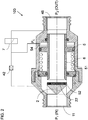
- a pressure reducing valve 100 includes a valve assembly defining a flow path from an inlet 11 to an outlet 45.
- a throttling arrangement forms part of the flow path.
- the throttling arrangement includes a displaceable throttling element (piston tube 51 ) displaceable between a fully-open position (to the right as shown) in which the flow path is open and a closed position (displaced to the left) in which the flow path is substantially blocked by closing of the displaceable throttling element against a seal plug 2.
- the phrase "substantially blocked” in this context typically refers to blocking sufficient to reduce any residual flow by at least two orders of magnitude relative to the flow rate when the valve is fully open.
- a spring 6 acts to bias the displaceable throttling element to the fully-open position.
- a control chamber 54 includes at least one pressure-actuated surface (right side of a piston 5 ) mechanically associated with the displaceable throttling element such that pressure within the control chamber 54 acts to displace the displaceable throttling element against the bias of spring 6 towards the closed position.
- the valve is preferably remotely switchable by changing the state of a switchable hydraulic control circuit that is in fluid connection with the inlet 11, the outlet 45 and the control chamber 54.
- the switchable hydraulic control circuit assumes:
- Switching of the hydraulic control circuit is most preferably electrically actuated, typically by use of a solenoid-controlled pilot valve, to switch between the first and second states.
- a solenoid-controlled pilot valve to switch between the first and second states.
- switching is performed directly by use of a three-port pilot valve 7 which alternately connects the control chamber 54 to either the outlet pressure or the inlet pressure.
- the switching is actuated by suitable control circuitry, forming part of a control system (not shown), as is well known in the art, and may include a local or otherwise hard-wired controller including circuitry and/or one or more processor configured for implementing a preset switching schedule, or to work together with other sensors or control components as part of a more complex control system.
- control system may include communication components for linking the controller to a local-area network and/or a wide-area network for implementing remote control of the valve from another location in the network, either automatically or manually.
- the control system of the present invention is essentially similar to that used in conventional systems, and will therefore not be described herein in further detail.
- switching of the hydraulic control circuit between the first and second states is achieved via a two-port on/off pilot valve 71, thereby rendering the pilot valve and pilot valve actuator particularly simple, reliable and low-cost.
- the operational principle of the hydraulic control circuit according to this approach is best understood with reference to FIG. 2 .
- the hydraulic control circuit as shown here includes a flow restriction 42 deployed within a control circuit flow path interconnecting between the fluid connection to the inlet 11 and the control chamber 54, while the on/off valve 7 controls a fluid interconnection between the control chamber 54 and the fluid connection to the outlet 45.
- the hydraulic control loop defines an open loop flow from a region of inlet pressure to a region of outlet pressure. Since the flow restriction 42 is designed to be the primary flow impedance in that loop, the flow through the control loop stabilizes at a (very small) flow rate when the pressure drop across the flow restriction is substantially equal to the pressure difference between the inlet and the outlet.
- control chamber 54 located downstream of the flow restriction, is effectively maintained at outlet pressure P 2 , thereby providing the desired pressure reduction regulation functionality.
- pilot valve control modalities may be used to implement the invention, such as for example, a hydraulically actuated pilot valve, or a manually-switchable control valve.
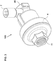
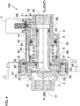
- FIGS. 3-7 Further details of a particularly preferred exemplary implementation of a valve according to the operating principles of FIG. 2 are illustrated in FIGS. 3-7 .
- the flow restriction is implemented as a labyrinth 42
- the control circuit flow path includes, sequentially, a filter configuration provided by a set of slots 24, a stilling chamber 25 to reduce turbulence in water that has passed the filter and to allow settling of any solids before reaching the labyrinth, and the labyrinth 42.
- valve 100 here is formed primarily from a valve closure 1, providing threaded inlet 11, which is in threaded engagement with a valve base 4, which provides threaded outlet 45.
- Pressure regulation is achieved by a sliding motion of a piston 5 which slides in sealing contact with a cylinder 41 of base 4, sealed by an O-ring 91.
- Motion of the piston 5 is governed by the balance of forces between the pressure in a control chamber 54 acting against force in a spring element 6, preferably a helical compression spring.
- Throttling of flow through valve 100 is achieved by sliding motion of a closing edge (rim) 52 of a piston tube 51 integrated with piston 5, as the rim moves towards and away from a closure surface 22 (optionally a resilient seal) of seal plug 2.
- Seal plug 2 is held in place by a number of ribs 23 which suspend the seal plug relative to a flow-guiding ring 21 which forms part of flow pathways 12 from inlet 11 to the piston cylinder 41.
- a number of filter slots 24 formed in flow-guiding ring 21 allow egress of a small filtered part of the flow to an annular stilling chamber 25, where turbulence is reduced and any small entrained solid particles tend to settle.
- Water is fed from stilling chamber 25 via a flow passage 32 to the inlet of a labyrinth 42.
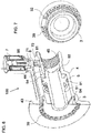
- the labyrinth is shown here formed by a series of baffles 39 supported by a labyrinth bracket 3 so as to abut adjacent surfaces of valve base 4, as best seen in FIGS. 5 (region 'A'), 6 and 7, so as to define a long, thin meandering flow path extending annularly around the valve structure.
- FIG. 7 shows labyrinth bracket 3 from the downstream side.
- An elongated passageway 43 through valve body 4 defines an outlet from labyrinth 42 which connects via the solenoid valve chamber 72 and a connecting passageway 44 to control chamber 54.
- Solenoid valve chamber 72 is also connected via solenoid valve orifice 8 and drain passage 81 to outlet flow path near outlet 45.
- Solenoid plunger 71 is selectively displaced by the solenoid to either open or seal orifice 8.
- a set of O-ring seals 91, 92, 93, 94, 95 and 96 provide seals between the various components, where seals 91, 92 and 93 are sliding seals and seals 94, 95 and 96 are static seals.
- a vent hole (not shown) preferably allows venting of the volume containing spring 6 to the atmosphere.
- the upstream pressure P 1 is throttled down to a desired output pressure as water flows through the passageway between the plug seal 22 and the piston closure 52 (rim).
- a preset force from spring 6 drives the piston 5 to open the valve, which is balanced by the downstream pressure P 2 acting on piston 5 to close the valve.
- the pressure regulation is attained as the spring 6 force and the piston 5 force reach equilibrium. Should the downstream pressure P 2 rise, piston 5 force prevails over the spring 6 load, and the valve throttles down the downstream P 2 pressure, and vice versa.
- the control loop flow starts as the water enters the narrow and outwardly-fanned slots 24 which act as a coarse filter. From filter slots 24, water enters the stilling chamber 25, then passing through passageway 32 into labyrinth 42, across which the pressure drops from the upstream pressure P 1 to the downstream P 2 (preset) pressure.
- Labyrinth 42 defines a long and turbulent flow pathway F which achieves the required pressure reduction using a relatively large channel (compared to an equivalent flow impedance achieved using a capillary flow restriction), thereby minimizing risks of clogging. From labyrinth 42, the water flows through elongated passageway 43 into solenoid chamber 72 and to the control chamber 54 via passageway 44. Piston stopping ribs 53 ensure that control chamber 54 is never completely emptied.
- valve 100 then regulates the pressure P 2 as described above.
- solenoid plunger 71 When solenoid plunger 71 is actuated to close orifice 8, water flow through the control loop stops, and the pressure at solenoid chamber 72 and control chamber 54 rises from the dynamic downstream P 2 to the static upstream P 1 pressure. Thus the force on piston 5 increases beyond that of the regulation mode, and the valve is driven to its closed position, when the closure 52 is pressed against the plug seal 22.
- control chamber 54 may alternatively be implemented using a diaphragm-based structure, where the control pressure P C acts on a diaphragm that is mechanically linked with the displaceable throttling element.
- control pressure P C acts on a diaphragm that is mechanically linked with the displaceable throttling element.
Claims (8)
- Soupape de réduction de pression (100) comprenant :(a) un ensemble de soupape définissant une voie de passage d'une entrée (11) à une sortie (45) ;(b) un agencement d'étranglement formant une partie de ladite voie de passage, ledit agencement d'étranglement comprenant un tube déplaçable (51) ayant un rebord, ledit tube déplaçable étant déplaçable par rapport à une surface de fermeture d'un tournant (2) entre une position complètement ouverte dans laquelle ledit rebord est espacé de ladite surface de fermeture de sorte que ladite voie de passage est ouverte, ladite voie de passage passant entre ledit rebord et ladite surface de fermeture et à travers ledit tube déplaçable, et une position fermée dans laquelle ledit rebord se ferme contre ladite surface de fermeture de sorte que ladite voie de passage est sensiblement bloquée ;(c) un ressort (6) agissant pour déplacer ledit tube déplaçable vers ladite position complètement ouverte ;(d) une chambre de commande (54) comportant au moins une surface de piston actionnée par pression (5) intégrée audit tube (51) et circonscrivant celui-ci de telle sorte que la pression au sein de ladite chambre de commande (54) agisse de manière à déplacer ledit tube déplaçable (51) contre ledit ressort (6) vers ladite position fermée ;
caractérisée en ce que la soupape de réduction de pression comprend en outre(e) un circuit de commande hydraulique commutable en liaison fluidique avec ladite entrée, ladite sortie et ladite chambre de commande, ledit circuit de commande hydraulique commutable étant configuré pour adopter :(i) un premier état dans lequel une pression au sein de ladite chambre de commande (PC) est égalisée avec une pression de sortie (P2), de telle sorte qu'un équilibre entre la pression de la chambre de commande et la force dudit ressort réalise la régulation de la pression de sortie, et(ii) un second état dans lequel la pression au sein de ladite chambre de commande (PC) est égalisée avec une pression d'entrée (P1), surmontant ainsi la force dudit ressort pour fermer la soupape. - Soupape de réduction de pression (100) selon la revendication 1, ledit circuit de commande hydraulique étant configuré pour être actionné électriquement afin de commuter entre lesdits premier et second états.
- Soupape de réduction de pression (100) selon la revendication 1, la commutation dudit circuit de commande hydraulique entre lesdits premier et second états étant réalisée par l'intermédiaire d'une soupape pilote à trois orifices (7).
- Soupape de réduction de pression (100) selon la revendication 1, la commutation dudit circuit de commande hydraulique entre lesdits premier et second états étant réalisée par l'intermédiaire d'une soupape pilote marche/arrêt à deux orifices (71).
- Soupape de réduction de pression (100) selon la revendication 4, ledit circuit de commande hydraulique comprenant une restriction de passage (42) déployée au sein d'une voie de passage de circuit de commande fournissant une interconnexion entre ladite connexion de fluide à ladite entrée (11) et ladite chambre de commande (54), et ladite soupape marche/arrêt commandant une interconnexion de fluide entre ladite chambre de commande (54) et ladite connexion de fluide à ladite sortie (45).
- Soupape de réduction de pression (100) selon la revendication 5, ladite restriction de passage étant mise en œuvre sous la forme d'un labyrinthe.
- Soupape de réduction de pression (100) selon la revendication 6, ladite voie de passage de circuit de commande comportant, séquentiellement, une configuration de filtre (24), une chambre de tranquillisation (25) et ledit labyrinthe (42).
- Soupape de réduction de pression (100) selon la revendication 6 ou 7, ledit labyrinthe définissant une voie de passage sinueuse s'étendant de manière annulaire autour de la soupape.
Applications Claiming Priority (2)
| Application Number | Priority Date | Filing Date | Title |
|---|---|---|---|
| US201762467145P | 2017-03-05 | 2017-03-05 | |
| PCT/IL2018/050246 WO2018163161A1 (fr) | 2017-03-05 | 2018-03-05 | Robinet réducteur de pression avec arrêt |
Publications (3)
| Publication Number | Publication Date |
|---|---|
| EP3593021A1 EP3593021A1 (fr) | 2020-01-15 |
| EP3593021A4 EP3593021A4 (fr) | 2020-01-15 |
| EP3593021B1 true EP3593021B1 (fr) | 2021-12-01 |
Family
ID=63447593
Family Applications (1)
| Application Number | Title | Priority Date | Filing Date |
|---|---|---|---|
| EP18764360.6A Active EP3593021B1 (fr) | 2017-03-05 | 2018-03-05 | Robinet réducteur de pression avec arrêt |
Country Status (8)
| Country | Link |
|---|---|
| US (1) | US11144077B2 (fr) |
| EP (1) | EP3593021B1 (fr) |
| CN (1) | CN110352314A (fr) |
| AU (1) | AU2018230272B2 (fr) |
| EA (1) | EA039861B1 (fr) |
| ES (1) | ES2909118T3 (fr) |
| MX (1) | MX2019010463A (fr) |
| WO (1) | WO2018163161A1 (fr) |
Families Citing this family (9)
| Publication number | Priority date | Publication date | Assignee | Title |
|---|---|---|---|---|
| US10906052B2 (en) | 2017-05-26 | 2021-02-02 | Nelson Irrigation Corporation | Drain check in pressure regulator |
| CN112236735A (zh) | 2018-04-17 | 2021-01-15 | 尼尔森灌溉公司 | 多功能压力调节阀 |
| US11933408B2 (en) | 2018-04-17 | 2024-03-19 | Nelson Irrigation Corporation | Multi-function pressure regulation valve |
| EP3953785B1 (fr) * | 2019-04-08 | 2024-04-24 | Netafim Ltd. | Vanne réductrice de pression avec mécanisme d'arrêt |
| US11713816B1 (en) | 2019-08-22 | 2023-08-01 | Colt Irrigation, LLC | Pressure loss mitigation and durable valve |
| US11408515B2 (en) | 2020-01-29 | 2022-08-09 | Nelson Irrigation Corporation | Pressure regulator having an oblique valve seat |
| US11703892B2 (en) * | 2020-11-12 | 2023-07-18 | Griswold Industries | Pressure regulator |
| IT202100012794A1 (it) * | 2021-05-18 | 2022-11-18 | Komet Austria Gmbh | Regolatore di pressione per un liquido con flusso deviato |
| CN116428414B (zh) * | 2023-04-19 | 2023-12-29 | 安徽威迈光机电科技有限公司 | 一种水下防冲击波保护装置 |
Citations (1)
| Publication number | Priority date | Publication date | Assignee | Title |
|---|---|---|---|---|
| US2996074A (en) * | 1954-03-01 | 1961-08-15 | John S Page | Fluid pressure actuated shut-off valve |
Family Cites Families (19)
| Publication number | Priority date | Publication date | Assignee | Title |
|---|---|---|---|---|
| US570727A (en) * | 1896-11-03 | Valve mechanism | ||
| US2329001A (en) * | 1941-11-25 | 1943-09-07 | Randolph B Delmore | Pilot operated valve |
| FR1485692A (fr) * | 1966-05-11 | 1967-06-23 | Vanne perfectionnée | |
| US4586533A (en) * | 1985-07-01 | 1986-05-06 | Crosby Valve & Gage Company | Non-flowing modulating pilot operated relief valve |
| US4609008A (en) * | 1985-09-11 | 1986-09-02 | Anderson-Greenwood Usa, Inc. | Non-flowing pressure responsive pilot valve |
| CN85109329B (zh) * | 1985-12-26 | 1988-07-20 | 庄凤龄 | 先导式溢流阀 |
| FR2617562B1 (fr) * | 1987-07-01 | 1989-11-10 | Verdelet Alain | Ensemble de vanne a clapet |
| US6035878A (en) * | 1997-09-22 | 2000-03-14 | Fisher Controls International, Inc. | Diagnostic device and method for pressure regulator |
| US6374853B1 (en) * | 2000-11-30 | 2002-04-23 | Lindsay Manufacturing Company | Combined pressure regulator and shut-off valve |
| US6752169B2 (en) * | 2002-10-31 | 2004-06-22 | Lindsay Manufacturing Co. | Pressure regulator and shut-off valve |
| CN2828493Y (zh) * | 2005-08-29 | 2006-10-18 | 新疆天业(集团)有限公司 | 一体化自动稳压阀 |
| GB2450125A (en) * | 2007-06-13 | 2008-12-17 | Aquavent Uk Ltd | Pressure reducing valve control |
| US8136545B2 (en) * | 2008-05-20 | 2012-03-20 | Emerson Process Management Regulator Technologies, Inc. | Apparatus to regulate fluid flow |
| EP2166423B1 (fr) * | 2008-09-19 | 2017-12-20 | Isomatic A/S | Vanne de liquide équilibrée |
| US8678029B2 (en) | 2011-05-11 | 2014-03-25 | Nelson Irrigation Corporation | Pressure regulator with remotely controlled shut-off valve |
| US9176505B2 (en) * | 2012-12-28 | 2015-11-03 | Emerson Process Management Regulator Technologies, Inc. | Backpressure regulator with easy pump start-up |
| EP2886834A1 (fr) * | 2013-12-20 | 2015-06-24 | IMI Hydronic Engineering International SA | Vanne et procédé de commande de vanne dans un conduit de fluide |
| EP3092537A1 (fr) * | 2014-01-08 | 2016-11-16 | Global Agricultural Technology & Engineering, LLC | Système d'alimentation en fluide |
| US10429859B2 (en) * | 2018-10-03 | 2019-10-01 | Don Duffin | Pressure regulator |
-
2018
- 2018-03-05 ES ES18764360T patent/ES2909118T3/es active Active
- 2018-03-05 EP EP18764360.6A patent/EP3593021B1/fr active Active
- 2018-03-05 AU AU2018230272A patent/AU2018230272B2/en active Active
- 2018-03-05 US US16/491,174 patent/US11144077B2/en active Active
- 2018-03-05 WO PCT/IL2018/050246 patent/WO2018163161A1/fr unknown
- 2018-03-05 EA EA201991737A patent/EA039861B1/ru unknown
- 2018-03-05 MX MX2019010463A patent/MX2019010463A/es unknown
- 2018-03-05 CN CN201880014822.1A patent/CN110352314A/zh active Pending
Patent Citations (1)
| Publication number | Priority date | Publication date | Assignee | Title |
|---|---|---|---|---|
| US2996074A (en) * | 1954-03-01 | 1961-08-15 | John S Page | Fluid pressure actuated shut-off valve |
Also Published As
| Publication number | Publication date |
|---|---|
| EP3593021A1 (fr) | 2020-01-15 |
| AU2018230272A1 (en) | 2019-09-12 |
| BR112019018397A2 (pt) | 2020-04-07 |
| EA201991737A1 (ru) | 2020-03-10 |
| MX2019010463A (es) | 2019-10-15 |
| US20200026313A1 (en) | 2020-01-23 |
| US11144077B2 (en) | 2021-10-12 |
| ES2909118T3 (es) | 2022-05-05 |
| EA039861B1 (ru) | 2022-03-21 |
| WO2018163161A1 (fr) | 2018-09-13 |
| AU2018230272B2 (en) | 2024-03-07 |
| CN110352314A (zh) | 2019-10-18 |
| EP3593021A4 (fr) | 2020-01-15 |
Similar Documents
| Publication | Publication Date | Title |
|---|---|---|
| EP3593021B1 (fr) | Robinet réducteur de pression avec arrêt | |
| KR102167326B1 (ko) | 폐쇄 보조되는 유동 제어 시스템 및 제어 밸브 | |
| US8424836B2 (en) | Bidirectional force feedback poppet valve | |
| US8276612B2 (en) | System and method for hydraulically managing fluid pressure downstream from a main valve | |
| US3322281A (en) | Filter assembly having plural check valves | |
| US4967791A (en) | Pressure activated check valve | |
| US20070290152A1 (en) | Poppet valve | |
| US9599243B1 (en) | Inline relief valve with parabolic piston face | |
| CN109690060A (zh) | 用于车辆压力容器的通气流量调节器 | |
| US11048280B2 (en) | Pressure regulator | |
| US3493008A (en) | Pressure balanced regulating valve | |
| US3556464A (en) | Self-draining pressure actuated valve | |
| RU2688043C2 (ru) | Система защиты резервуара от переполнения | |
| EP1709353B1 (fr) | Dispositif de regulation du flux applique a des soupapes fonctionnant sous pression differentielle | |
| GB2512228A (en) | Snapshut valve | |
| JPH03282078A (ja) | 電動3方弁 | |
| BR112019018397B1 (pt) | Válvula de redução de pressão | |
| KR20010013329A (fr) | Actionneur a soupape pour commutateur de pression d'un systeme hydraulique | |
| JPH0447166B2 (fr) | ||
| KR100421461B1 (ko) | 정유량/정온 조절밸브 | |
| US3875965A (en) | Safety valve for controlling flow | |
| KR100421460B1 (ko) | 정유량/정온 조절밸브 | |
| JP4098737B2 (ja) | 減圧弁装置 | |
| JPH09317916A (ja) | 自動調整弁装置 | |
| WO1986004400A1 (fr) | Element de logique pour la commutation des fluides, a position normalement fermee |
Legal Events
| Date | Code | Title | Description |
|---|---|---|---|
| STAA | Information on the status of an ep patent application or granted ep patent |
Free format text: STATUS: THE INTERNATIONAL PUBLICATION HAS BEEN MADE |
|
| PUAI | Public reference made under article 153(3) epc to a published international application that has entered the european phase |
Free format text: ORIGINAL CODE: 0009012 |
|
| STAA | Information on the status of an ep patent application or granted ep patent |
Free format text: STATUS: REQUEST FOR EXAMINATION WAS MADE |
|
| 17P | Request for examination filed |
Effective date: 20190826 |
|
| A4 | Supplementary search report drawn up and despatched |
Effective date: 20191121 |
|
| AK | Designated contracting states |
Kind code of ref document: A1 Designated state(s): AL AT BE BG CH CY CZ DE DK EE ES FI FR GB GR HR HU IE IS IT LI LT LU LV MC MK MT NL NO PL PT RO RS SE SI SK SM TR |
|
| AX | Request for extension of the european patent |
Extension state: BA ME |
|
| DAV | Request for validation of the european patent (deleted) | ||
| DAX | Request for extension of the european patent (deleted) | ||
| STAA | Information on the status of an ep patent application or granted ep patent |
Free format text: STATUS: EXAMINATION IS IN PROGRESS |
|
| 17Q | First examination report despatched |
Effective date: 20200723 |
|
| STAA | Information on the status of an ep patent application or granted ep patent |
Free format text: STATUS: EXAMINATION IS IN PROGRESS |
|
| GRAP | Despatch of communication of intention to grant a patent |
Free format text: ORIGINAL CODE: EPIDOSNIGR1 |
|
| STAA | Information on the status of an ep patent application or granted ep patent |
Free format text: STATUS: GRANT OF PATENT IS INTENDED |
|
| INTG | Intention to grant announced |
Effective date: 20210211 |
|
| GRAJ | Information related to disapproval of communication of intention to grant by the applicant or resumption of examination proceedings by the epo deleted |
Free format text: ORIGINAL CODE: EPIDOSDIGR1 |
|
| STAA | Information on the status of an ep patent application or granted ep patent |
Free format text: STATUS: EXAMINATION IS IN PROGRESS |
|
| GRAS | Grant fee paid |
Free format text: ORIGINAL CODE: EPIDOSNIGR3 |
|
| STAA | Information on the status of an ep patent application or granted ep patent |
Free format text: STATUS: GRANT OF PATENT IS INTENDED |
|
| GRAP | Despatch of communication of intention to grant a patent |
Free format text: ORIGINAL CODE: EPIDOSNIGR1 |
|
| INTC | Intention to grant announced (deleted) | ||
| INTG | Intention to grant announced |
Effective date: 20210629 |
|
| GRAJ | Information related to disapproval of communication of intention to grant by the applicant or resumption of examination proceedings by the epo deleted |
Free format text: ORIGINAL CODE: EPIDOSDIGR1 |
|
| GRAL | Information related to payment of fee for publishing/printing deleted |
Free format text: ORIGINAL CODE: EPIDOSDIGR3 |
|
| STAA | Information on the status of an ep patent application or granted ep patent |
Free format text: STATUS: EXAMINATION IS IN PROGRESS |
|
| INTC | Intention to grant announced (deleted) | ||
| GRAP | Despatch of communication of intention to grant a patent |
Free format text: ORIGINAL CODE: EPIDOSNIGR1 |
|
| STAA | Information on the status of an ep patent application or granted ep patent |
Free format text: STATUS: GRANT OF PATENT IS INTENDED |
|
| GRAF | Information related to payment of grant fee modified |
Free format text: ORIGINAL CODE: EPIDOSCIGR3 |
|
| GRAA | (expected) grant |
Free format text: ORIGINAL CODE: 0009210 |
|
| STAA | Information on the status of an ep patent application or granted ep patent |
Free format text: STATUS: THE PATENT HAS BEEN GRANTED |
|
| INTG | Intention to grant announced |
Effective date: 20211007 |
|
| AK | Designated contracting states |
Kind code of ref document: B1 Designated state(s): AL AT BE BG CH CY CZ DE DK EE ES FI FR GB GR HR HU IE IS IT LI LT LU LV MC MK MT NL NO PL PT RO RS SE SI SK SM TR |
|
| REG | Reference to a national code |
Ref country code: GB Ref legal event code: FG4D |
|
| REG | Reference to a national code |
Ref country code: AT Ref legal event code: REF Ref document number: 1452066 Country of ref document: AT Kind code of ref document: T Effective date: 20211215 Ref country code: CH Ref legal event code: EP |
|
| REG | Reference to a national code |
Ref country code: IE Ref legal event code: FG4D |
|
| REG | Reference to a national code |
Ref country code: DE Ref legal event code: R096 Ref document number: 602018027545 Country of ref document: DE |
|
| REG | Reference to a national code |
Ref country code: NL Ref legal event code: FP |
|
| REG | Reference to a national code |
Ref country code: LT Ref legal event code: MG9D |
|
| REG | Reference to a national code |
Ref country code: AT Ref legal event code: MK05 Ref document number: 1452066 Country of ref document: AT Kind code of ref document: T Effective date: 20211201 |
|
| PG25 | Lapsed in a contracting state [announced via postgrant information from national office to epo] |
Ref country code: RS Free format text: LAPSE BECAUSE OF FAILURE TO SUBMIT A TRANSLATION OF THE DESCRIPTION OR TO PAY THE FEE WITHIN THE PRESCRIBED TIME-LIMIT Effective date: 20211201 Ref country code: LT Free format text: LAPSE BECAUSE OF FAILURE TO SUBMIT A TRANSLATION OF THE DESCRIPTION OR TO PAY THE FEE WITHIN THE PRESCRIBED TIME-LIMIT Effective date: 20211201 Ref country code: FI Free format text: LAPSE BECAUSE OF FAILURE TO SUBMIT A TRANSLATION OF THE DESCRIPTION OR TO PAY THE FEE WITHIN THE PRESCRIBED TIME-LIMIT Effective date: 20211201 Ref country code: BG Free format text: LAPSE BECAUSE OF FAILURE TO SUBMIT A TRANSLATION OF THE DESCRIPTION OR TO PAY THE FEE WITHIN THE PRESCRIBED TIME-LIMIT Effective date: 20220301 Ref country code: AT Free format text: LAPSE BECAUSE OF FAILURE TO SUBMIT A TRANSLATION OF THE DESCRIPTION OR TO PAY THE FEE WITHIN THE PRESCRIBED TIME-LIMIT Effective date: 20211201 |
|
| REG | Reference to a national code |
Ref country code: ES Ref legal event code: FG2A Ref document number: 2909118 Country of ref document: ES Kind code of ref document: T3 Effective date: 20220505 |
|
| PG25 | Lapsed in a contracting state [announced via postgrant information from national office to epo] |
Ref country code: SE Free format text: LAPSE BECAUSE OF FAILURE TO SUBMIT A TRANSLATION OF THE DESCRIPTION OR TO PAY THE FEE WITHIN THE PRESCRIBED TIME-LIMIT Effective date: 20211201 Ref country code: PL Free format text: LAPSE BECAUSE OF FAILURE TO SUBMIT A TRANSLATION OF THE DESCRIPTION OR TO PAY THE FEE WITHIN THE PRESCRIBED TIME-LIMIT Effective date: 20211201 Ref country code: NO Free format text: LAPSE BECAUSE OF FAILURE TO SUBMIT A TRANSLATION OF THE DESCRIPTION OR TO PAY THE FEE WITHIN THE PRESCRIBED TIME-LIMIT Effective date: 20220301 Ref country code: LV Free format text: LAPSE BECAUSE OF FAILURE TO SUBMIT A TRANSLATION OF THE DESCRIPTION OR TO PAY THE FEE WITHIN THE PRESCRIBED TIME-LIMIT Effective date: 20211201 Ref country code: HR Free format text: LAPSE BECAUSE OF FAILURE TO SUBMIT A TRANSLATION OF THE DESCRIPTION OR TO PAY THE FEE WITHIN THE PRESCRIBED TIME-LIMIT Effective date: 20211201 Ref country code: GR Free format text: LAPSE BECAUSE OF FAILURE TO SUBMIT A TRANSLATION OF THE DESCRIPTION OR TO PAY THE FEE WITHIN THE PRESCRIBED TIME-LIMIT Effective date: 20220302 |
|
| PG25 | Lapsed in a contracting state [announced via postgrant information from national office to epo] |
Ref country code: SM Free format text: LAPSE BECAUSE OF FAILURE TO SUBMIT A TRANSLATION OF THE DESCRIPTION OR TO PAY THE FEE WITHIN THE PRESCRIBED TIME-LIMIT Effective date: 20211201 Ref country code: SK Free format text: LAPSE BECAUSE OF FAILURE TO SUBMIT A TRANSLATION OF THE DESCRIPTION OR TO PAY THE FEE WITHIN THE PRESCRIBED TIME-LIMIT Effective date: 20211201 Ref country code: RO Free format text: LAPSE BECAUSE OF FAILURE TO SUBMIT A TRANSLATION OF THE DESCRIPTION OR TO PAY THE FEE WITHIN THE PRESCRIBED TIME-LIMIT Effective date: 20211201 Ref country code: PT Free format text: LAPSE BECAUSE OF FAILURE TO SUBMIT A TRANSLATION OF THE DESCRIPTION OR TO PAY THE FEE WITHIN THE PRESCRIBED TIME-LIMIT Effective date: 20220401 Ref country code: EE Free format text: LAPSE BECAUSE OF FAILURE TO SUBMIT A TRANSLATION OF THE DESCRIPTION OR TO PAY THE FEE WITHIN THE PRESCRIBED TIME-LIMIT Effective date: 20211201 Ref country code: CZ Free format text: LAPSE BECAUSE OF FAILURE TO SUBMIT A TRANSLATION OF THE DESCRIPTION OR TO PAY THE FEE WITHIN THE PRESCRIBED TIME-LIMIT Effective date: 20211201 |
|
| PGFP | Annual fee paid to national office [announced via postgrant information from national office to epo] |
Ref country code: IT Payment date: 20220331 Year of fee payment: 5 |
|
| REG | Reference to a national code |
Ref country code: DE Ref legal event code: R097 Ref document number: 602018027545 Country of ref document: DE |
|
| PG25 | Lapsed in a contracting state [announced via postgrant information from national office to epo] |
Ref country code: IS Free format text: LAPSE BECAUSE OF FAILURE TO SUBMIT A TRANSLATION OF THE DESCRIPTION OR TO PAY THE FEE WITHIN THE PRESCRIBED TIME-LIMIT Effective date: 20220401 |
|
| REG | Reference to a national code |
Ref country code: DE Ref legal event code: R119 Ref document number: 602018027545 Country of ref document: DE |
|
| PLBE | No opposition filed within time limit |
Free format text: ORIGINAL CODE: 0009261 |
|
| STAA | Information on the status of an ep patent application or granted ep patent |
Free format text: STATUS: NO OPPOSITION FILED WITHIN TIME LIMIT |
|
| PG25 | Lapsed in a contracting state [announced via postgrant information from national office to epo] |
Ref country code: MC Free format text: LAPSE BECAUSE OF FAILURE TO SUBMIT A TRANSLATION OF THE DESCRIPTION OR TO PAY THE FEE WITHIN THE PRESCRIBED TIME-LIMIT Effective date: 20211201 Ref country code: DK Free format text: LAPSE BECAUSE OF FAILURE TO SUBMIT A TRANSLATION OF THE DESCRIPTION OR TO PAY THE FEE WITHIN THE PRESCRIBED TIME-LIMIT Effective date: 20211201 Ref country code: AL Free format text: LAPSE BECAUSE OF FAILURE TO SUBMIT A TRANSLATION OF THE DESCRIPTION OR TO PAY THE FEE WITHIN THE PRESCRIBED TIME-LIMIT Effective date: 20211201 |
|
| REG | Reference to a national code |
Ref country code: CH Ref legal event code: PL |
|
| 26N | No opposition filed |
Effective date: 20220902 |
|
| PG25 | Lapsed in a contracting state [announced via postgrant information from national office to epo] |
Ref country code: SI Free format text: LAPSE BECAUSE OF FAILURE TO SUBMIT A TRANSLATION OF THE DESCRIPTION OR TO PAY THE FEE WITHIN THE PRESCRIBED TIME-LIMIT Effective date: 20211201 |
|
| REG | Reference to a national code |
Ref country code: BE Ref legal event code: MM Effective date: 20220331 |
|
| PG25 | Lapsed in a contracting state [announced via postgrant information from national office to epo] |
Ref country code: LU Free format text: LAPSE BECAUSE OF NON-PAYMENT OF DUE FEES Effective date: 20220305 Ref country code: LI Free format text: LAPSE BECAUSE OF NON-PAYMENT OF DUE FEES Effective date: 20220331 Ref country code: IE Free format text: LAPSE BECAUSE OF NON-PAYMENT OF DUE FEES Effective date: 20220305 Ref country code: DE Free format text: LAPSE BECAUSE OF NON-PAYMENT OF DUE FEES Effective date: 20221001 Ref country code: CH Free format text: LAPSE BECAUSE OF NON-PAYMENT OF DUE FEES Effective date: 20220331 |
|
| PG25 | Lapsed in a contracting state [announced via postgrant information from national office to epo] |
Ref country code: BE Free format text: LAPSE BECAUSE OF NON-PAYMENT OF DUE FEES Effective date: 20220331 |
|
| PGFP | Annual fee paid to national office [announced via postgrant information from national office to epo] |
Ref country code: FR Payment date: 20230314 Year of fee payment: 6 |
|
| PG25 | Lapsed in a contracting state [announced via postgrant information from national office to epo] |
Ref country code: IT Free format text: LAPSE BECAUSE OF NON-PAYMENT OF DUE FEES Effective date: 20220305 |
|
| PGFP | Annual fee paid to national office [announced via postgrant information from national office to epo] |
Ref country code: TR Payment date: 20230224 Year of fee payment: 6 Ref country code: GB Payment date: 20230317 Year of fee payment: 6 |
|
| PGFP | Annual fee paid to national office [announced via postgrant information from national office to epo] |
Ref country code: NL Payment date: 20230316 Year of fee payment: 6 |
|
| PGFP | Annual fee paid to national office [announced via postgrant information from national office to epo] |
Ref country code: ES Payment date: 20230412 Year of fee payment: 6 |
|
| PGFP | Annual fee paid to national office [announced via postgrant information from national office to epo] |
Ref country code: NL Payment date: 20240318 Year of fee payment: 7 |