EP3592589B1 - Hybridmodul mit integrierter sensoreinrichtung sowie hybridantriebsstrang mit hybridmodul - Google Patents
Hybridmodul mit integrierter sensoreinrichtung sowie hybridantriebsstrang mit hybridmodul Download PDFInfo
- Publication number
- EP3592589B1 EP3592589B1 EP18705819.3A EP18705819A EP3592589B1 EP 3592589 B1 EP3592589 B1 EP 3592589B1 EP 18705819 A EP18705819 A EP 18705819A EP 3592589 B1 EP3592589 B1 EP 3592589B1
- Authority
- EP
- European Patent Office
- Prior art keywords
- hybrid module
- sensor
- hybrid
- support bearings
- separating clutch
- Prior art date
- Legal status (The legal status is an assumption and is not a legal conclusion. Google has not performed a legal analysis and makes no representation as to the accuracy of the status listed.)
- Not-in-force
Links
Images


Classifications
-
- B—PERFORMING OPERATIONS; TRANSPORTING
- B60—VEHICLES IN GENERAL
- B60K—ARRANGEMENT OR MOUNTING OF PROPULSION UNITS OR OF TRANSMISSIONS IN VEHICLES; ARRANGEMENT OR MOUNTING OF PLURAL DIVERSE PRIME-MOVERS IN VEHICLES; AUXILIARY DRIVES FOR VEHICLES; INSTRUMENTATION OR DASHBOARDS FOR VEHICLES; ARRANGEMENTS IN CONNECTION WITH COOLING, AIR INTAKE, GAS EXHAUST OR FUEL SUPPLY OF PROPULSION UNITS IN VEHICLES
- B60K6/00—Arrangement or mounting of plural diverse prime-movers for mutual or common propulsion, e.g. hybrid propulsion systems comprising electric motors and internal combustion engines
- B60K6/20—Arrangement or mounting of plural diverse prime-movers for mutual or common propulsion, e.g. hybrid propulsion systems comprising electric motors and internal combustion engines the prime-movers consisting of electric motors and internal combustion engines, e.g. HEVs
- B60K6/42—Arrangement or mounting of plural diverse prime-movers for mutual or common propulsion, e.g. hybrid propulsion systems comprising electric motors and internal combustion engines the prime-movers consisting of electric motors and internal combustion engines, e.g. HEVs characterised by the architecture of the hybrid electric vehicle
- B60K6/48—Parallel type
-
- B—PERFORMING OPERATIONS; TRANSPORTING
- B60—VEHICLES IN GENERAL
- B60K—ARRANGEMENT OR MOUNTING OF PROPULSION UNITS OR OF TRANSMISSIONS IN VEHICLES; ARRANGEMENT OR MOUNTING OF PLURAL DIVERSE PRIME-MOVERS IN VEHICLES; AUXILIARY DRIVES FOR VEHICLES; INSTRUMENTATION OR DASHBOARDS FOR VEHICLES; ARRANGEMENTS IN CONNECTION WITH COOLING, AIR INTAKE, GAS EXHAUST OR FUEL SUPPLY OF PROPULSION UNITS IN VEHICLES
- B60K6/00—Arrangement or mounting of plural diverse prime-movers for mutual or common propulsion, e.g. hybrid propulsion systems comprising electric motors and internal combustion engines
- B60K6/20—Arrangement or mounting of plural diverse prime-movers for mutual or common propulsion, e.g. hybrid propulsion systems comprising electric motors and internal combustion engines the prime-movers consisting of electric motors and internal combustion engines, e.g. HEVs
- B60K6/22—Arrangement or mounting of plural diverse prime-movers for mutual or common propulsion, e.g. hybrid propulsion systems comprising electric motors and internal combustion engines the prime-movers consisting of electric motors and internal combustion engines, e.g. HEVs characterised by apparatus, components or means specially adapted for HEVs
- B60K6/30—Arrangement or mounting of plural diverse prime-movers for mutual or common propulsion, e.g. hybrid propulsion systems comprising electric motors and internal combustion engines the prime-movers consisting of electric motors and internal combustion engines, e.g. HEVs characterised by apparatus, components or means specially adapted for HEVs characterised by chargeable mechanical accumulators, e.g. flywheels
-
- B—PERFORMING OPERATIONS; TRANSPORTING
- B60—VEHICLES IN GENERAL
- B60K—ARRANGEMENT OR MOUNTING OF PROPULSION UNITS OR OF TRANSMISSIONS IN VEHICLES; ARRANGEMENT OR MOUNTING OF PLURAL DIVERSE PRIME-MOVERS IN VEHICLES; AUXILIARY DRIVES FOR VEHICLES; INSTRUMENTATION OR DASHBOARDS FOR VEHICLES; ARRANGEMENTS IN CONNECTION WITH COOLING, AIR INTAKE, GAS EXHAUST OR FUEL SUPPLY OF PROPULSION UNITS IN VEHICLES
- B60K6/00—Arrangement or mounting of plural diverse prime-movers for mutual or common propulsion, e.g. hybrid propulsion systems comprising electric motors and internal combustion engines
- B60K6/20—Arrangement or mounting of plural diverse prime-movers for mutual or common propulsion, e.g. hybrid propulsion systems comprising electric motors and internal combustion engines the prime-movers consisting of electric motors and internal combustion engines, e.g. HEVs
- B60K6/22—Arrangement or mounting of plural diverse prime-movers for mutual or common propulsion, e.g. hybrid propulsion systems comprising electric motors and internal combustion engines the prime-movers consisting of electric motors and internal combustion engines, e.g. HEVs characterised by apparatus, components or means specially adapted for HEVs
- B60K6/38—Arrangement or mounting of plural diverse prime-movers for mutual or common propulsion, e.g. hybrid propulsion systems comprising electric motors and internal combustion engines the prime-movers consisting of electric motors and internal combustion engines, e.g. HEVs characterised by apparatus, components or means specially adapted for HEVs characterised by the driveline clutches
- B60K6/387—Actuated clutches, i.e. clutches engaged or disengaged by electric, hydraulic or mechanical actuating means
-
- B—PERFORMING OPERATIONS; TRANSPORTING
- B60—VEHICLES IN GENERAL
- B60K—ARRANGEMENT OR MOUNTING OF PROPULSION UNITS OR OF TRANSMISSIONS IN VEHICLES; ARRANGEMENT OR MOUNTING OF PLURAL DIVERSE PRIME-MOVERS IN VEHICLES; AUXILIARY DRIVES FOR VEHICLES; INSTRUMENTATION OR DASHBOARDS FOR VEHICLES; ARRANGEMENTS IN CONNECTION WITH COOLING, AIR INTAKE, GAS EXHAUST OR FUEL SUPPLY OF PROPULSION UNITS IN VEHICLES
- B60K6/00—Arrangement or mounting of plural diverse prime-movers for mutual or common propulsion, e.g. hybrid propulsion systems comprising electric motors and internal combustion engines
- B60K6/20—Arrangement or mounting of plural diverse prime-movers for mutual or common propulsion, e.g. hybrid propulsion systems comprising electric motors and internal combustion engines the prime-movers consisting of electric motors and internal combustion engines, e.g. HEVs
- B60K6/22—Arrangement or mounting of plural diverse prime-movers for mutual or common propulsion, e.g. hybrid propulsion systems comprising electric motors and internal combustion engines the prime-movers consisting of electric motors and internal combustion engines, e.g. HEVs characterised by apparatus, components or means specially adapted for HEVs
- B60K6/40—Arrangement or mounting of plural diverse prime-movers for mutual or common propulsion, e.g. hybrid propulsion systems comprising electric motors and internal combustion engines the prime-movers consisting of electric motors and internal combustion engines, e.g. HEVs characterised by apparatus, components or means specially adapted for HEVs characterised by the assembly or relative disposition of components
-
- B—PERFORMING OPERATIONS; TRANSPORTING
- B60—VEHICLES IN GENERAL
- B60K—ARRANGEMENT OR MOUNTING OF PROPULSION UNITS OR OF TRANSMISSIONS IN VEHICLES; ARRANGEMENT OR MOUNTING OF PLURAL DIVERSE PRIME-MOVERS IN VEHICLES; AUXILIARY DRIVES FOR VEHICLES; INSTRUMENTATION OR DASHBOARDS FOR VEHICLES; ARRANGEMENTS IN CONNECTION WITH COOLING, AIR INTAKE, GAS EXHAUST OR FUEL SUPPLY OF PROPULSION UNITS IN VEHICLES
- B60K6/00—Arrangement or mounting of plural diverse prime-movers for mutual or common propulsion, e.g. hybrid propulsion systems comprising electric motors and internal combustion engines
- B60K6/20—Arrangement or mounting of plural diverse prime-movers for mutual or common propulsion, e.g. hybrid propulsion systems comprising electric motors and internal combustion engines the prime-movers consisting of electric motors and internal combustion engines, e.g. HEVs
- B60K6/22—Arrangement or mounting of plural diverse prime-movers for mutual or common propulsion, e.g. hybrid propulsion systems comprising electric motors and internal combustion engines the prime-movers consisting of electric motors and internal combustion engines, e.g. HEVs characterised by apparatus, components or means specially adapted for HEVs
- B60K6/40—Arrangement or mounting of plural diverse prime-movers for mutual or common propulsion, e.g. hybrid propulsion systems comprising electric motors and internal combustion engines the prime-movers consisting of electric motors and internal combustion engines, e.g. HEVs characterised by apparatus, components or means specially adapted for HEVs characterised by the assembly or relative disposition of components
- B60K6/405—Housings
-
- F—MECHANICAL ENGINEERING; LIGHTING; HEATING; WEAPONS; BLASTING
- F16—ENGINEERING ELEMENTS AND UNITS; GENERAL MEASURES FOR PRODUCING AND MAINTAINING EFFECTIVE FUNCTIONING OF MACHINES OR INSTALLATIONS; THERMAL INSULATION IN GENERAL
- F16D—COUPLINGS FOR TRANSMITTING ROTATION; CLUTCHES; BRAKES
- F16D13/00—Friction clutches
- F16D13/22—Friction clutches with axially-movable clutching members
- F16D13/38—Friction clutches with axially-movable clutching members with flat clutching surfaces, e.g. discs
- F16D13/52—Clutches with multiple lamellae ; Clutches in which three or more axially moveable members are fixed alternately to the shafts to be coupled and are pressed from one side towards an axially-located member
-
- F—MECHANICAL ENGINEERING; LIGHTING; HEATING; WEAPONS; BLASTING
- F16—ENGINEERING ELEMENTS AND UNITS; GENERAL MEASURES FOR PRODUCING AND MAINTAINING EFFECTIVE FUNCTIONING OF MACHINES OR INSTALLATIONS; THERMAL INSULATION IN GENERAL
- F16D—COUPLINGS FOR TRANSMITTING ROTATION; CLUTCHES; BRAKES
- F16D25/00—Fluid-actuated clutches
- F16D25/08—Fluid-actuated clutches with fluid-actuated member not rotating with a clutching member
- F16D25/082—Fluid-actuated clutches with fluid-actuated member not rotating with a clutching member the line of action of the fluid-actuated members co-inciding with the axis of rotation
-
- F—MECHANICAL ENGINEERING; LIGHTING; HEATING; WEAPONS; BLASTING
- F16—ENGINEERING ELEMENTS AND UNITS; GENERAL MEASURES FOR PRODUCING AND MAINTAINING EFFECTIVE FUNCTIONING OF MACHINES OR INSTALLATIONS; THERMAL INSULATION IN GENERAL
- F16F—SPRINGS; SHOCK-ABSORBERS; MEANS FOR DAMPING VIBRATION
- F16F15/00—Suppression of vibrations in systems; Means or arrangements for avoiding or reducing out-of-balance forces, e.g. due to motion
- F16F15/10—Suppression of vibrations in rotating systems by making use of members moving with the system
- F16F15/14—Suppression of vibrations in rotating systems by making use of members moving with the system using masses freely rotating with the system, i.e. uninvolved in transmitting driveline torque, e.g. rotative dynamic dampers
- F16F15/1407—Suppression of vibrations in rotating systems by making use of members moving with the system using masses freely rotating with the system, i.e. uninvolved in transmitting driveline torque, e.g. rotative dynamic dampers the rotation being limited with respect to the driving means
- F16F15/145—Masses mounted with play with respect to driving means thus enabling free movement over a limited range
- F16F15/1457—Systems with a single mass
-
- H—ELECTRICITY
- H02—GENERATION; CONVERSION OR DISTRIBUTION OF ELECTRIC POWER
- H02K—DYNAMO-ELECTRIC MACHINES
- H02K11/00—Structural association of dynamo-electric machines with electric components or with devices for shielding, monitoring or protection
- H02K11/30—Structural association with control circuits or drive circuits
- H02K11/33—Drive circuits, e.g. power electronics
-
- B—PERFORMING OPERATIONS; TRANSPORTING
- B60—VEHICLES IN GENERAL
- B60K—ARRANGEMENT OR MOUNTING OF PROPULSION UNITS OR OF TRANSMISSIONS IN VEHICLES; ARRANGEMENT OR MOUNTING OF PLURAL DIVERSE PRIME-MOVERS IN VEHICLES; AUXILIARY DRIVES FOR VEHICLES; INSTRUMENTATION OR DASHBOARDS FOR VEHICLES; ARRANGEMENTS IN CONNECTION WITH COOLING, AIR INTAKE, GAS EXHAUST OR FUEL SUPPLY OF PROPULSION UNITS IN VEHICLES
- B60K6/00—Arrangement or mounting of plural diverse prime-movers for mutual or common propulsion, e.g. hybrid propulsion systems comprising electric motors and internal combustion engines
- B60K6/20—Arrangement or mounting of plural diverse prime-movers for mutual or common propulsion, e.g. hybrid propulsion systems comprising electric motors and internal combustion engines the prime-movers consisting of electric motors and internal combustion engines, e.g. HEVs
- B60K6/42—Arrangement or mounting of plural diverse prime-movers for mutual or common propulsion, e.g. hybrid propulsion systems comprising electric motors and internal combustion engines the prime-movers consisting of electric motors and internal combustion engines, e.g. HEVs characterised by the architecture of the hybrid electric vehicle
- B60K6/48—Parallel type
- B60K2006/4825—Electric machine connected or connectable to gearbox input shaft
-
- B—PERFORMING OPERATIONS; TRANSPORTING
- B60—VEHICLES IN GENERAL
- B60Y—INDEXING SCHEME RELATING TO ASPECTS CROSS-CUTTING VEHICLE TECHNOLOGY
- B60Y2200/00—Type of vehicle
- B60Y2200/90—Vehicles comprising electric prime movers
- B60Y2200/92—Hybrid vehicles
-
- B—PERFORMING OPERATIONS; TRANSPORTING
- B60—VEHICLES IN GENERAL
- B60Y—INDEXING SCHEME RELATING TO ASPECTS CROSS-CUTTING VEHICLE TECHNOLOGY
- B60Y2400/00—Special features of vehicle units
- B60Y2400/48—Vibration dampers, e.g. dual mass flywheels
-
- Y—GENERAL TAGGING OF NEW TECHNOLOGICAL DEVELOPMENTS; GENERAL TAGGING OF CROSS-SECTIONAL TECHNOLOGIES SPANNING OVER SEVERAL SECTIONS OF THE IPC; TECHNICAL SUBJECTS COVERED BY FORMER USPC CROSS-REFERENCE ART COLLECTIONS [XRACs] AND DIGESTS
- Y02—TECHNOLOGIES OR APPLICATIONS FOR MITIGATION OR ADAPTATION AGAINST CLIMATE CHANGE
- Y02T—CLIMATE CHANGE MITIGATION TECHNOLOGIES RELATED TO TRANSPORTATION
- Y02T10/00—Road transport of goods or passengers
- Y02T10/60—Other road transportation technologies with climate change mitigation effect
- Y02T10/62—Hybrid vehicles
Definitions
- the invention relates to a hybrid module for a (hybrid) drive train of a motor vehicle, such as a car, truck, bus or other commercial vehicle, with a housing, a separating clutch and an intermediate shaft, wherein a rotating component of the separating clutch that is coupled or can be coupled to an electrical machine is rotationally fixed to the Intermediate shaft is connected and the intermediate shaft is mounted rotatably about an axis of rotation relative to the housing by means of two support bearings.
- the invention also relates to a hybrid drive train with the hybrid module.
- a disadvantage of known hybrid modules is that a relatively large amount of installation space is taken up by the sensors of the sensor devices. This disadvantage is increased by the arrangement of the sensor devices implemented up to now.
- the support bearings are arranged at a distance from one another in the axial direction, i.e. along the axis of rotation, that a receiving space is formed axially between them, at least part of a sensor device being arranged / housed / positioned in the receiving space.
- the housing has an intermediate wall running in the radial direction and the two support bearings are received / held on a radial inside of the intermediate wall.
- an outer bearing ring of the respective support bearing is received / held on the radial inside of the partition wall.
- the support bearings are particularly solid.
- the intermediate wall has a sleeve area arranged radially within a plurality of friction elements of the separating clutch, the support bearings being received (preferably directly) on a radial inside of the sleeve area.
- the sleeve area further preferably adjoins in the radial direction within a radially extending disk area of the intermediate wall.
- the disk area itself is arranged axially offset to the separating clutch / to friction elements of the separating clutch. This further optimizes the use of installation space.
- the support bearings are advantageously arranged directly or indirectly on a radial outer side of the intermediate shaft designed as a hollow shaft or solid shaft.
- the sensor device it is also expedient if it has at least one sensor, more preferably a plurality of sensors, which sensor (s) is / are arranged in the receiving space. As a result, the construction of the sensor device is kept particularly simple.
- the at least one sensor is designed to detect a rotational speed (/ rotational speed), a temperature, a torque and / or a position, preferably an angular position.
- the sensor is preferably designed as a resolver. As a result, a particularly compact sensor is integrated in the receiving space.
- the at least one sensor is connected / coupled (data-transmitting) to an evaluation unit of the sensor device by means of a wireless connection or, more preferably, by means of a wired connection.
- each temperature sensor preferably contacts a bearing ring of one of the support bearings so that it detects the temperature of the respective bearing ring.
- the at least one sensor is designed as a speed sensor / angle of rotation sensor, for example in the form of a resolver. The speed sensor / angle of rotation sensor is firmly connected to the housing and interacts with an encoder connected to the intermediate shaft in a rotationally fixed manner.
- the support bearings further preferably have different diameters and are further preferably arranged on different steps / shoulders of the intermediate shaft.
- CSC concentric slave cylinder
- the invention relates to a hybrid drive train for a motor vehicle, with the hybrid module according to the invention according to at least one of the embodiments described above.
- a sensor system (sensor device) is thus integrated in a hybrid module preferably designed as a P2 hybrid system.
- a sensor system (sensor device; preferably for detecting a speed / rotational speed, a temperature, a torque, a position or the like) is arranged between two support bearings of an intermediate shaft.
- the structure of the hybrid module 1 according to the invention can be seen particularly clearly in a first exemplary embodiment.
- the hybrid module 1 is part of a hybrid drive train of a motor vehicle during operation.
- the hybrid module 1 is then preferably, viewed along the torque transmission path, inserted between an output shaft 20 of an internal combustion engine and a transmission.
- the hybrid module 1 typically has a coupling device consisting of at least one, preferably a plurality of partial couplings, of which only one (first) separating coupling 3 is shown for the sake of clarity.
- the (first) separating clutch 3 is used for the optional rotationally fixed coupling of the output shaft 20 to an intermediate shaft 4 of the hybrid module 1.
- the hybrid module 1 also typically has an electric machine / an electric motor.
- the electrical machine is axially parallel, that is, with an axis of rotation of its rotor parallel to an axis of rotation 8 of the intermediate shaft 4 / the output shaft 20 (crankshaft).
- the electric machine is part of the hybrid module 1, but can in principle also be viewed as a separate part from the hybrid module 1.
- the hybrid module 1 of the first exemplary embodiment has a torsional vibration damper in the form of a dual mass flywheel 22 on a side facing the output shaft 20.
- the dual mass flywheel 22 is in Fig. 1 already connected to the output shaft 20 in a rotationally fixed manner.
- the dual-mass flywheel 22 is connected on the input side to the output shaft 20.
- the dual-mass flywheel 22 is non-rotatably connected to a rotating component 15, hereinafter referred to as the second rotating component 15, of the first separating clutch 3.
- the first separating clutch 3 is designed as a friction clutch.
- the first separating clutch 3 is designed as a dry clutch in this exemplary embodiment, but can in principle also be designed as a wet clutch.
- a first rotary component 5 of the first separating clutch 3 provided next to the second rotary component 15 interacts with the second rotary component 15 via a plurality of friction elements 13a and 13b.
- the two rotary components 5, 15 are connected to one another by their friction elements 13a, 13b in a typical manner in a frictionally locking manner.
- the friction elements 13a and 13b and thus the Rotary components 5, 15 are arranged freely rotatable relative to one another.
- the two rotating components 5, 15 are arranged to be rotatable about a central axis of rotation 8 of the separating clutch 3 / of the hybrid module 1.
- the first separating clutch 3 is designed as a friction disk clutch.
- Each rotary component 5, 15 thus has a plurality of friction elements 13a, 13b in the form of friction disks.
- the first rotating component 5 has a first carrier 23 designed as an inner carrier / inner disk carrier.
- a plurality of first friction elements 13a are received in a rotationally fixed manner on this first carrier 23, namely on a sleeve-shaped support region 24 of the first carrier 23.
- the first friction elements 13a are also received on the support region 24 of the first carrier 23 such that they can be displaced relative to one another in the axial direction.
- the first carrier 23 has a shaped toothing on which the first friction elements 13a are received in a rotationally fixed and axially displaceable manner.
- a second friction element 13b of the second rotary component 15 is arranged between each two adjacent first friction elements 13a.
- the second rotary component 15 has a second carrier 25 in the form of an outer carrier / outer disk carrier, which receives the second friction elements 13b in a rotationally fixed and axially displaceable manner relative to one another.
- the rotor of the electrical machine which is not shown here for the sake of clarity, is also drivingly coupled to the first rotating component 5 of the separating clutch 3.
- the rotor on the part of its rotor shaft is coupled to the first rotating component 5 via a traction means 26 (here belt, alternatively also chain, etc.).
- the first rotating component 5 has a traction device receiving area 27 which receives the traction device 26 in a form-fitting and / or force-fitting manner.
- the use of chains, for example, has proven itself at this point.
- the receiving area 27 is arranged radially outside of the support area 24 and the friction elements 13a, 13b.
- the first carrier 23 thus also forms a rotor / pulley carrier.
- the first rotating component 5 is rotatably connected on the part of its first carrier 23 to an intermediate shaft 4, which in turn is rotatably supported about the axis of rotation 8.
- a serration 28 is used for the rotationally fixed connection between the first carrier 23 and the intermediate shaft 4.
- the intermediate shaft 4 is used in operation in a typical manner for connecting the first rotary component 5 to a further partial coupling of the coupling device, such as preferably to a partial coupling of a double coupling of the hybrid module 1.
- the intermediate shaft 4 is mounted rotatably relative to a housing 2 of the hybrid module 1.
- two support bearings 6, 7 arranged along the axis of rotation 8 / spaced apart from one another in the axial direction are provided.
- a first support bearing 6 is arranged closer to the dual-mass flywheel 22 in the axial direction than a second support bearing 7.
- Both support bearings 6, 7 are designed as ball bearings.
- the second support bearing 7 is designed as an angular contact ball bearing.
- the two support bearings 6, 7 are accommodated on an intermediate wall 11 of the housing 2.
- the intermediate wall 11 forms a sleeve region 14 which extends in the axial direction and on whose radial inner side 12 the two support bearings 6, 7 are received.
- the respective support bearing 6, 7 is held with an outer bearing ring 29a, 29b on this sleeve area 14 / on the partition 11.
- the support bearings 6, 7 have different diameters.
- the sleeve area 14 is consequently designed in a stepped manner.
- the first support bearing 6 is received with its bearing outer ring 29a; the second support bearing 7 with its bearing outer ring 29b is received at a second step, which is expanded radially outward compared to this first step.
- the support bearings 6, 7 are also received at two different stages of the intermediate shaft 4.
- a first stage of the intermediate shaft 4 is used to hold the first support bearing 6 / an inner bearing ring 30a of the first support bearing 6 and is radially smaller than a second stage which is used to hold the second support bearing 7 / an inner bearing ring 30b of the second support bearing 7.
- a receiving space 9 for receiving components of a sensor device 10 is now formed in the axial direction between the two support bearings 6, 7. This is especially good in Fig. 2 evident.
- Figs. 3 to 5 In this context, different sensors 17 of the sensor device 10 for attachment in this receiving space 9 are shown.
- Several sensors 17 of the sensor device 10 are arranged in the receiving space 9.
- the sensors 17 are each designed as temperature sensors.
- the sensors 17 are each connected to one of the bearing rings 29a, 29b, 30a, 30b.
- a single (first) sensor 17 is attached to the bearing outer ring 29a of the first support bearing 6 in a contacting manner.
- Another (second) individual sensor 17 is attached to the bearing outer ring 29b of the second support bearing 7 in a contacting manner.
- Another (third) sensor 17 is attached to the bearing inner ring 30a of the first support bearing 6 in a contacting manner.
- Another (fourth) sensor 17 is attached to the bearing inner ring 30b of the second support bearing 7 in a contacting manner.
- the respective sensor 17 is connected to an evaluation unit of the sensor device 10 via a wired connection, which is indicated here in sections by a cable 18, in a further data-transmitting and energy-transmitting manner.
- the evaluation unit is not shown further for the sake of clarity.
- the wired connection penetrates the intermediate wall 11 with respect to the axis of rotation 8, preferably in the radial direction and / or at least partially in the axial direction.
- a single sensor 17 of the sensor device 10 is arranged in the receiving space 9.
- the sensor 17 is in Fig. 4 designed as a speed sensor.
- the sensor 17 interacts with a transmitter 31, the transmitter 31 forming a component that can be measured by the sensor 17.
- the transmitter 31 is arranged radially inside the sensor 17.
- the sensor 17 is firmly attached to the partition 11 / the housing 2.
- the sensor 17 is directed with its measuring range in the radial direction inward towards the transmitter 31.
- the encoder 31 is connected to the intermediate shaft 4 in a rotationally fixed manner.
- the encoder 31 is attached to an outer side 16 of the intermediate shaft 4. As a result, in particular a rotational speed / rotational speed of the intermediate shaft 4 can be detected.
- the transmitter 31 is also designed as a transmitter wheel.
- the encoder 31 thus has a plurality of lugs / elevations distributed around the circumference, which also enable the (angular) position / angular position of the intermediate shaft 4 to be detected during operation.
- the rotary connection with the rotor also allows conclusions to be drawn about the rotational speed / rotational speed and position of the rotor.
- Fig. 4 Combined with Fig. 5 is like in Fig. 4 a single sensor 17 of the sensor device 10 implemented in the form of a speed sensor.
- the sensor 17 of the in Fig. 5 The variant shown differs from the sensor 17 in FIG Fig. 4 variant shown in that its measuring range is aligned in the axial direction.
- the transmitter 31 projects beyond the sensor 17 in a certain overlap area in the radial direction, so that the sensor 17 can in turn detect the elevations of the transmitter 31 in the form of the transmitter wheel.
- the first separating clutch 3 can be actuated by means of a slave cylinder 19.
- the slave cylinder 19 is designed as a concentric (ring-shaped) slave cylinder 19 (CSC).
- the slave cylinder 19 is fixed to the housing, namely fixed by the partition 11.
- the slave cylinder 19 has a cylinder housing 23 which is arranged and fastened on a radial outer side of the sleeve area 14.
- An (annular) piston 33 is slidably received in the cylinder housing 32.
- a preload spring 37 acts on the piston 33 in an axial direction.
- the piston 33 also interacts with an actuation bearing 34 and this actuation bearing 34 in turn interacts with a pressure pot 35.
- the pressure pot 35 is pretensioned by a plate spring 36 in such a way that when the slave cylinder 19 is not actuated it engaged the first separating clutch 3 by pressing the friction elements 13a, 13b into it Position forces.
- the slave cylinder 19 is therefore implemented as a release / release system.
- the plate spring 36 is in Fig. 1 illustrated in dashed lines in further pivot positions.
- the plate spring 36 per se is firmly connected axially to the first rotary component 5 in the region of its pivot point / is axially firmly supported on it.
- the plate spring 36 is braced in the axial direction relative to the first rotary component 5.
- a modulation spring can also be present.
- a further second embodiment of the hybrid module 1 according to the invention is illustrated.
- the intermediate shaft 4 forms a flywheel / a counter pressure plate 39 of a further clutch 38 / Partial coupling of the coupling device with off.
- the counter-pressure plate 39 is non-rotatably connected to a tubular component / base body 40 of the intermediate shaft 4.
- the torsional vibration damper is designed here in the form of a single-mass flywheel.
- the first carrier 23 is also connected to the intermediate shaft 4 by riveting.
- the electrical machine 21 is contained directly in the housing 2 of the hybrid module 1.
- a stator 41 and the rotor 42 of the electrical machine 21 interacting therewith are integrated in the housing 2.
- the rotor 42 is attached directly to the receiving area 27 of the first carrier 23.
- the first carrier 23 thus forms a rotor arm directly.
- the intermediate shaft 4 is also as in FIG Figs. 6th and 7th formed in several parts.
- the counter pressure plate 39 is in turn connected to the base body 40 in a rotationally fixed manner.
- the sensor 17 received in the receiving space 9 is designed as a resolver.
- the installation space (receiving space 9) between the support bearings 6, 7 of the intermediate shaft 4 is used for the measuring sensor system (sensor device 10).
- This installation space 9 has the advantage that a wide variety of sensors can be installed at this point. These can be, for example, sensors 17 for speed, temperature (preferably for bearing monitoring), torque, position (resolver) or the like. Due to the installation position of the sensor system 10, both wireless sensor system 10 and sensor system 10 with cables 18 can be installed, since these can be routed “to the outside” via the partition 11. Both radially and axially operating systems are conceivable. Furthermore, the installation location (receiving space 9) is ideally protected against contamination.
- the installation position for the measuring sensor system 10 is both for coaxially arranged hybrid modules 1 and also suitable for axially parallel arrangements. It is also suitable for 48V systems as well as for high-voltage systems.
- a K0 clutch / motor disconnect clutch (first disconnect clutch 3) which is normally closed serves as the starting point.
- the execution of this clutch 3 as a dry multi-disc clutch or wet clutch is accordingly possible.
- the electric machine is arranged axially parallel and coupled to the K0 3, for example, via a belt drive, chain drive, etc.
- a rotor / belt pulley carrier (first carrier 23) of the K0 3 is also designed as an inner disk carrier.
- the carrier 23 is also advantageously designed with shaped lamellar teeth.
- the lamella package (totality of first and second friction elements 13a, 13b) of the K0 3 is preloaded by a plate spring 36, if necessary. including modulation spring.
- the actuation of the K0 3 takes place preferably by means of an annular piston CSC (slave cylinder 19).
- a bearing preload spring is also preferably present therein.
- a coaxial electric machine 21 is also correspondingly possible.
- the DMF dual mass flywheel 22
- the reference numeral 25 denotes an outer disk carrier made in one piece.
- Reference numeral 2 denotes a locking ring 43 for supporting a bearing 46 of the outer disk carrier 25 and a plate spring support plate 44.
- Reference numeral 39 denotes a flywheel which is integrally formed with a flange and a toothing for a connection to a shaft (intermediate shaft 4).
- the reference number 36 denotes a plate spring which has a diameter which is smaller than an inner diameter of a driver toothing.
- Reference number 4 denotes a shaft which can be designed as a hollow shaft or solid shaft.
- Reference numeral 11 designates an intermediate wall which has passages 45 with a thread for screwing to a housing 2.
Landscapes
- Engineering & Computer Science (AREA)
- Mechanical Engineering (AREA)
- Chemical & Material Sciences (AREA)
- Combustion & Propulsion (AREA)
- Transportation (AREA)
- General Engineering & Computer Science (AREA)
- Microelectronics & Electronic Packaging (AREA)
- Power Engineering (AREA)
- Physics & Mathematics (AREA)
- Acoustics & Sound (AREA)
- Aviation & Aerospace Engineering (AREA)
- Hybrid Electric Vehicles (AREA)
- Mechanical Operated Clutches (AREA)
- Hydraulic Clutches, Magnetic Clutches, Fluid Clutches, And Fluid Joints (AREA)
Description
- Die Erfindung betrifft ein Hybridmodul für einen (hybriden) Antriebsstrang eines Kraftfahrzeuges, wie eines Pkws, Lkws, Busses oder sonstigen Nutzfahrzeuges, mit einem Gehäuse, einer Trennkupplung sowie einer Zwischenwelle, wobei ein mit einer elektrischen Maschine gekoppelter oder koppelbarer Drehbestandteil der Trennkupplung drehfest mit der Zwischenwelle verbunden ist und die Zwischenwelle relativ zu dem Gehäuse mittels zweier Stützlager um eine Drehachse rotierbar gelagert ist. Zudem betrifft die Erfindung einen Hybridantriebsstrang mit dem Hybridmodul.
- Gattungsgemäßer Stand der Technik ist bereits hinlänglich bekannt. Beispielsweise offenbart die
WO 2016/070 878 A1 ein Hybridmodul für einen Antriebsstrang eines Kraftfahrzeuges, mit einem elektrischen Antriebsmotor, der in dem Hybridmodul integriert ist. Weiterer gattungsgemäßer Stand der Technik nach dem Oberbegriff von Anspruch 1 ist in derUS 2005/206349 A1 und derUS 2010/069192 A1 gezeigt. - Des Weiteren ist es bekannt, die Betriebszustände der elektrischen Maschinen dieser Hybridmodule zu überwachen. Dafür ist es prinzipiell möglich, verschiedene Sensoreinrichtungen heranzuziehen, um bspw. die Drehzahl oder eine Position eines Rotors der elektrischen Maschine zu erfassen.
- Ein Nachteil bekannter Hybridmodule besteht jedoch darin, dass relativ viel Bauraum durch die Sensorik der Sensoreinrichtungen eingenommen wird. Dieser Nachteil wird durch die bisher umgesetzte Anordnung der Sensoreinrichtungen verstärkt.
- Es ist daher die Aufgabe der vorliegenden Erfindung, diese aus dem Stand der Technik bekannten Nachteile zu beheben und insbesondere ein Hybridmodul zur Verfügung zu stellen, das einerseits den derzeit anstehenden Entwicklungen hinsichtlich der Industrie 4.0 zur Überwachung von Systemen Schritt hält, andererseits die immer beschränkteren Bauraumvorgaben einhält.
- Dies wird erfindungsgemäß mit den Merkmalen des Anspruchs 1 gelöst. Die Stützlager sind derart in axialer Richtung, d.h. entlang der Drehachse, beabstandet zueinander angeordnet sind, dass axial zwischen ihnen ein Aufnahmeraum gebildet ist, wobei in dem Aufnahmeraum zumindest ein Teil einer Sensoreinrichtung angeordnet / untergebracht / positioniert ist.
- Durch das geschickte Ausnutzen dieses ohnehin vorhandenen Bauraums sind bestehende Hybridmodule ohne Sensoreinrichtung einfach adaptierbar, ohne dass zwingend zusätzlicher Bauraum zur Verfügung gestellt werden muss. Eine möglichst kompakte Ausbildung eines Hybridmoduls, das dennoch ausreichend überwachbar ist, ist somit geschaffen.
- Erfindungsgemäß ist außerdem vorgesehen, dass das Gehäuse eine in radialer Richtung verlaufende Zwischenwand aufweist und an einer radialen Innenseite der Zwischenwand die beiden Stützlager aufgenommen / gehalten sind. Insbesondere ist an der radialen Innenseite der Zwischenwand jeweils ein Lageraußenring des jeweiligen Stützlagers aufgenommen / gehalten. Dadurch sind die Stützlager besonders solide aufgenommen.
- Zudem ist es erfindungsgemäß vorgesehen, dass die Zwischenwand einen radial innerhalb mehrerer Reibelemente der Trennkupplung angeordneten Hülsenbereich aufweist, wobei an einer radialen Innenseite des Hülsenbereiches (vorzugsweise unmittelbar) die Stützlager aufgenommen sind.
- Der Hülsenbereich schließt sich weiter bevorzugt in radialer Richtung innerhalb eines sich radial erstreckenden Scheibenbereichs der Zwischenwand an. Der Scheibenbereich an sich ist axial versetzt zu der Trennkupplung / zu Reibelementen der Trennkupplung angeordnet. Dadurch wird die Bauraumnutzung weiter optimiert.
- Weitere vorteilhafte Ausführungsformen sind mit den Unteransprüchen beansprucht und nachfolgend näher erläutert
- Die Stützlager sind vorteilhafterweise unmittelbar oder mittelbar an einer radialen Außenseite der als Hohlwelle oder Vollwelle ausgebildeten Zwischenwelle angeordnet.
- Hinsichtlich der Sensoreinrichtung ist es weiterhin zweckmäßig, wenn diese zumindest einen Sensor, weiter bevorzugt mehrere Sensoren, aufweist, welcher / welche Sensor/-en in dem Aufnahmeraum angeordnet ist / sind. Dadurch ist der Aufbau der Sensoreinrichtung besonders einfach gehalten.
- Von Vorteil ist es, wenn der zumindest eine Sensor zum Erfassen einer Drehzahl (/Drehgeschwindigkeit), einer Temperatur, eines Drehmoments und/oder einer Position, vorzugsweise einer Winkellage, ausgebildet ist. Vorzugsweise ist der Sensor als ein Resolver ausgebildet. Dadurch ist ein besonders kompakt ausgebildeter Sensor in dem Aufnahmeraum integriert.
- Der zumindest eine Sensor ist mittels einer kabellosen Verbindung oder weiter bevorzugt mittels einer kabelgebundenen Verbindung mit einer Auswerteeinheit der Sensoreinrichtung (datenübertragend) verbunden / gekoppelt.
- Gemäß einer besonders bevorzugten Ausführung sind mehrere Sensoren in Form von Temperatursensoren der Sensoreinrichtung in dem Aufnahmeraum vorgesehen. Jeder Temperatursensor kontaktiert dabei bevorzugt einen Lagerring eines der Stützlager, sodass er die Temperatur des jeweiligen Lagerrings erfasst. Gemäß einer weiter bevorzugten Ausführung ist der zumindest eine Sensor als ein Drehzahlsensor / Drehwinkelsensor, etwa in Form eines Resolvers, ausgebildet. Der Drehzahlsensor / Drehwinkelsensor ist fest mit dem Gehäuse verbunden und wirkt mit einem drehfest mit der Zwischenwelle verbundenen Geber zusammen.
- Die Stützlager weisen weiter bevorzugt unterschiedliche Durchmesser auf und sind weiter bevorzugt an unterschiedlichen Stufen / Absätzen der Zwischenwelle angeordnet.
- Ist ein zum Betätigen der Trennkupplung eingesetzter Nehmerzylinder, vorzugsweise in Form eines konzentrischen Nehmerzylinders (CSC) ausgebildet, radial zwischen den Stützlagern und mehreren Reibelementen der Trennkupplung positioniert, wird der vorhandene Bauraum noch intensiver genutzt.
- Zudem betrifft die Erfindung einen Hybridantriebsstrang für ein Kraftfahrzeug, mit dem erfindungsgemäßen Hybridmodul nach zumindest einer der zuvor beschriebenen Ausführungen.
- In anderen Worten ausgedrückt, ist somit erfindungsgemäß eine Sensorik (Sensoreinrichtung) bei einem vorzugsweise als P2-Hybridsystem ausgebildeten Hybridmodul integriert. Erfindungsgemäß ist ein Sensorsystem (Sensoreinrichtung; vorzugsweise zur Erfassung einer Geschwindigkeit / Drehzahl, einer Temperatur, eines Drehmoments, einer Position oder ähnlichem) zwischen zwei Stützlagern einer Zwischenwelle angeordnet.
- Die Erfindung wird nun nachfolgend anhand von Figuren in Verbindung mit unterschiedlichen Ausführungsbeispielen näher beschrieben.
- Es zeigen:
- Fig. 1
- eine Längsschnittdarstellung eines erfindungsgemäßen Hybridmoduls nach einem ersten Ausführungsbeispiel, wobei das Hybridmodul mit einem parallel zu einer Drehachse einer Trennkupplung angeordneten Elektromotor ausgestattet ist und der innere Aufbau des Hybridmoduls zu erkennen ist, wobei eine vorhandene Sensoreinrichtung des Hybridmoduls schematisch dargestellt ist,
- Fig. 2
- eine Längsschnittdarstellung des Hybridmoduls nach
Fig. 1 im Bereich der Trennkupplung, einer Zwischenwelle sowie eines zwischen zwei Stützlagern ausgebildeten Aufnahmeraums zur Aufnahme der Sensoreinrichtung, - Fig. 3
- eine Längsschnittdarstellung des teilweise abgebildeten Hybridmoduls, ähnlich zu
Fig. 2 , wobei die Sensoreinrichtung gemäß einer ersten Variante mit mehreren Temperatursensoren ausgestattet ist, - Fig. 4
- eine Längsschnittdarstellung des teilweise abgebildeten Hybridmoduls, ähnlich zu
Fig. 2 , wobei die Sensoreinrichtung gemäß einer zweiten Variante mit einem Drehzahlsensor ausgestattet ist und der Drehzahlsensor mit seinem Messbereich in radialer Richtung nach innen ausgerichtet ist, - Fig. 5
- eine Längsschnittdarstellung des teilweise abgebildeten Hybridmoduls, ähnlich zu
Fig. 2 , wobei die Sensoreinrichtung gemäß einer dritten Variante als Drehzahlsensor ausgebildet ist, mit seinem Messbereich in axialer Richtung ausgerichtet ist, - Fig. 6
- eine Längsschnittdarstellung eines erfindungsgemäßen Hybridmoduls nach einem zweiten Ausführungsbeispiel, wobei die Zwischenwelle zweiteilig ausgebildet ist,
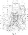
- Fig. 7
- eine perspektivische Darstellung des in
Fig. 6 in Längsrichtung geschnittenen Hybridmoduls, und - Fig. 8
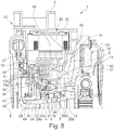
- eine Längsschnittdarstellung eines erfindungsgemäßen Hybridmoduls nach einem dritten Ausführungsbeispiel, wobei die elektrische Maschine nun koaxial zu der Drehachse der Trennkupplung angeordnet ist.
- Die Figuren sind lediglich schematischer Natur und dienen ausschließlich dem Verständnis der Erfindung. Die gleichen Elemente sind mit denselben Bezugszeichen versehen. Des Weiteren sind die unterschiedlichen Merkmale der verschiedenen Ausführungsbeispiele frei miteinander kombinierbar. Hinsichtlich der nachfolgend näher beschriebenen unterschiedlichen Ausführungsbeispiele sei darauf hingewiesen, dass die Ausführungsbeispiele allesamt prinzipiell gemäß dem ersten Ausführungsbeispiel aufgebaut sind sowie funktionieren, sodass der Kürze wegen lediglich die Unterschiede zu dem ersten Ausführungsbeispiel beschrieben sind.
- In der Verbindung mit
Fig. 1 ist das erfindungsgemäße Hybridmodul 1 gemäß einem ersten Ausführungsbeispiel im Aufbau besonders gut erkennbar. Das Hybridmodul 1 ist im Betrieb Bestandteil eines Hybridantriebsstranges eines Kraftfahrzeuges. Das Hybridmodul 1 ist dann vorzugsweise, entlang des Drehmomentübertragungspfades betrachtet, zwischen einer Ausgangswelle 20 einer Verbrennungskraftmaschine und einem Getriebe eingesetzt. Das Hybridmodul 1 weist auf typische Weise eine Kupplungseinrichtung bestehend aus zumindest einer, vorzugsweise mehreren Teilkupplungen, wovon der Übersichtlichkeit halber lediglich eine (erste) Trennkupplung 3 dargestellt ist, auf. Die (erste) Trennkupplung 3 dient zum wahlweisen drehfesten Koppeln der Ausgangswelle 20 mit einer Zwischenwelle 4 des Hybridmoduls 1. Auch weist das Hybridmodul 1 auf typische Weise eine elektrische Maschine / einen Elektromotor auf. Die elektrische Maschine ist in dieser Ausführung achsparallel, d.h. mit einer Drehachse ihres Rotors parallel zu einer Drehachse 8 der Zwischenwelle 4 / der Ausgangswelle 20 (Kurbelwelle) angeordnet. Die elektrische Maschine ist in diesem Ausführungsbeispiel Bestandteil des Hybridmoduls 1, kann jedoch prinzipiell auch als ein vom Hybridmodul 1 separater Bestandteil betrachtet werden. - Das Hybridmodul 1 des ersten Ausführungsbeispiels weist zu einer der Ausgangswelle 20 zugewandten Seite hin einen Drehschwingungsdämpfer in Form eines Zweimassenschwungrades 22 auf. Das Zweimassenschwungrad 22 ist in
Fig. 1 bereits drehfest mit der Ausgangswelle 20 verbunden. Das Zweimassenschwungrad 22 ist eingangsseitig mit der Ausgangswelle 20 verbunden. Ausgangsseitig ist das Zweimassenschwungrad 22 drehfest mit einem Drehbestandteil 15, nachfolgend als zweiter Drehbestandteil 15 bezeichnet, der ersten Trennkupplung 3 drehfest verbunden. - Die erste Trennkupplung 3 ist als eine Reibungskupplung ausgeführt. Die erste Trennkupplung 3 ist in diesem Ausführungsbeispiel als trockene Kupplung ausgeführt, kann jedoch prinzipiell auch als nass laufende Kupplung ausgeführt sein. Ein neben dem zweiten Drehbestandteil 15 vorgesehener erster Drehbestandteil 5 der ersten Trennkupplung 3 wirkt über mehrere Reibelemente 13a und 13b mit dem zweiten Drehbestandteil 15 zusammen. Die beiden Drehbestandteile 5, 15 sind in einer eingekuppelten Stellung der ersten Trennkupplung 3 seitens ihrer Reibelemente 13a, 13b auf typische Weise reibkraftschlüssig miteinander verbunden. In einer ausgekuppelten Stellung der ersten Trennkupplung 3 sind die Reibelemente 13a und 13b und somit die Drehbestanteile 5, 15 frei relativ zueinander verdrehbar angeordnet. Die beiden Drehbestandteile 5, 15 sind um eine zentrale Drehachse 8 der Trennkupplung 3 / des Hybridmoduls 1 drehbar angeordnet.
- Insbesondere ist die erste Trennkupplung 3 als eine Reiblamellenkupplung ausgestaltet. Somit weist jeder Drehbestandteil 5, 15 mehrere Reibelemente 13a, 13b in Form von Reiblamellen auf. Der erste Drehbestandteil 5 weist einen, als Innenträger / Innenlamellenträger ausgebildeten, ersten Träger 23 auf. An diesem ersten Träger 23, nämlich an einem hülsenförmigen Tragbereich 24 des ersten Trägers 23, sind mehrere erste Reibelemente 13a drehfest aufgenommen. Die ersten Reibelemente 13a sind zudem in axialer Richtung relativ zueinander verschiebbar an dem Tragbereich 24 des ersten Trägers 23 aufgenommen. Hierzu weist der erste Träger 23 eine ausgeformte Verzahnung auf, auf der die ersten Reibelemente 13a drehfest sowie axial verschiebbar aufgenommen sind. Zwischen je zwei benachbarten ersten Reibelementen 13a ist ein zweites Reibelement 13b des zweiten Drehbestandteils 15 angeordnet. Der zweite Drehbestandteil 15 weist einen zweiten Träger 25 in Form eines Außenträgers / Außenlamellenträgers auf, der die zweiten Reibelemente 13b drehfest sowie relativ zueinander axial verschiebbar aufnimmt.
- Mit dem ersten Drehbestandteil 5 der Trennkupplung 3 ist zudem der hier der Übersichtlichkeit halber nicht weiter dargestellte Rotor der elektrischen Maschine antreibend gekoppelt. Hierzu ist der Rotor seitens seiner Rotorwelle über ein Zugmittel 26 (hier Riemen, alternativ auch Kette, etc.) mit dem ersten Drehbestandteil 5 gekoppelt. Der erste Drehbestandteil 5 weist einen Zugmittelaufnahmebereich 27 auf, der das Zugmittel 26 form- und/oder kraftschlüssig aufnimmt. Bewährt hat sich beispielsweise der Einsatz von Ketten an dieser Stelle. Der Aufnahmebereich 27 ist radial außerhalb des Tragbereiches 24 sowie der Reibelemente 13a, 13b angeordnet. Der erste Träger 23 bildet somit auch einen Rotor- / Riemenscheiben-Träger aus.
- Der erste Drehbestandteil 5 ist, seitens seines ersten Trägers 23, mit einer Zwischenwelle 4, die wiederum um die Drehachse 8 drehbar gelagert ist, drehverbunden. In diesem Ausführungsbeispiel dient eine Kerbverzahnung 28 zur drehfesten Verbindung zwischen dem ersten Träger 23 und der Zwischenwelle 4. Die Zwischenwelle 4 dient im Betrieb auf typische Weise zur Verbindung des ersten Drehbestandteils 5 mit einer weiteren Teilkupplung der Kupplungseinrichtung, wie bevorzugt mit einer Teilkupplung einer Doppelkupplung des Hybridmoduls 1.
- Die Zwischenwelle 4 ist relativ zu einem Gehäuse 2 des Hybridmoduls 1 drehbar gelagert. Zu diesem Zwecke sind zwei entlang der Drehachse 8 / in axialer Richtung beabstandet zueinander angeordnete Stützlager 6, 7 vorgesehen. Ein erstes Stützlager 6 ist in axialer Richtung näher zu dem Zweimassenschwungrad 22 hin angeordnet als ein zweites Stützlager 7. Beide Stützlager 6, 7 sind als Kugellager ausgeführt. Das zweite Stützlager 7 ist als ein Schrägkugellager ausgeführt. Die beiden Stützlager 6, 7 sind an einer Zwischenwand 11 des Gehäuses 2 aufgenommen. Hierfür bildet die Zwischenwand 11 einen sich in axialer Richtung erstreckenden Hülsenbereich 14 aus, an dessen radialer Innenseite 12 die beiden Stützlager 6, 7 aufgenommen sind. Das jeweilige Stützlager 6, 7 ist mit einem Lageraußenring 29a, 29b an diesem Hülsenbereich 14 / an der Zwischenwand 11 gehalten.
- Die Stützlager 6, 7 weisen einen unterschiedlichen Durchmesser auf. Der Hülsenbereich 14 ist folglich gestuft ausgebildet ist. An einer ersten Stufe ist das erste Stützlager 6 mit seinem Lageraußenring 29a aufgenommen; an einer gegenüber dieser ersten Stufe radial nach außen erweiterten zweiten Stufe ist das zweite Stützlager 7 mit seinem Lageraußenring 29b aufgenommen. Dem entsprechend sind die Stützlager 6, 7 auch an zwei unterschiedlichen Stufen der Zwischenwelle 4 aufgenommen. Eine erste Stufe der Zwischenwelle 4 dient zur Aufnahme des ersten Stützlagers 6 / eines Lagerinnenrings 30a des ersten Stützlagers 6 und ist radial kleiner dimensioniert als eine zweite Stufe, die zur Aufnahme des zweiten Stützlagers 7 / eines Lagerinnenrings 30b des zweiten Stützlagers 7 dient.
- Erfindungsgemäß ist nun in axialer Richtung zwischen den beiden Stützlagern 6, 7 ein Aufnahmeraum 9 zur Aufnahme von Bestandteilen einer Sensoreinrichtung 10 ausgebildet. Dies ist auch besonders gut in
Fig. 2 ersichtlich. In Verbindung mit denFign. 3 bis 5 sind in diesem Zusammenhang unterschiedliche Sensoren 17 der Sensoreinrichtung 10 zum Anbringen in diesem Aufnahmeraum 9 dargestellt. - In
Fig. 3 sind mehrere Sensoren 17 der Sensoreinrichtung 10 in dem Aufnahmeraum 9 angeordnet. Die Sensoren 17 sind jeweils als Temperatursensoren ausgestaltet. Die Sensoren 17 sind jeweils mit einem der Lagerringe 29a, 29b, 30a, 30b verbunden. Somit ist ein einzelner (erster) Sensor 17 an dem Lageraußenring 29a des ersten Stützlagers 6 kontaktierend angebracht. Ein weiterer (zweiter) einzelner Sensor 17 ist an dem Lageraußenring 29b des zweiten Stützlagers 7 kontaktierend angebracht. Ein weiterer (dritter) Sensor 17 ist kontaktierend an dem Lagerinnenring 30a des ersten Stützlagers 6 angebracht. Ein weiterer (vierter) Sensor 17 ist an dem Lagerinnenring 30b des zweiten Stützlagers 7 kontaktierend angebracht. Der jeweilige Sensor 17 ist in diesem Ausführungsbeispiel über eine kabelgebundene Verbindung, die hier abschnittsweise seitens eines Kabels 18 angedeutet ist, mit einer Auswerteeinheit der Sensoreinrichtung 10 weiter datenübermittelnd und energieübertragend verbunden. Die Auswerteeinheit ist der Übersichtlichkeit halber nicht weiter dargestellt. Die kabelgebundene Verbindung durchdringt die Zwischenwand 11 in Bezug auf die Drehachse 8 bevorzugt in radialer Richtung und/oder zumindest teilweise in axialer Richtung. - In
Fig. 4 ist lediglich ein einziger Sensor 17 der Sensoreinrichtung 10 in dem Aufnahmeraum 9 angeordnet. Der Sensor 17 ist inFig. 4 als ein Drehzahlsensor ausgestaltet. Der Sensor 17 wirkt mit einem Geber 31 zusammen, wobei der Geber 31 einen durch den Sensor 17 messtechnisch erfassbaren Bestandteil ausbildet. Der Geber 31 ist radial innerhalb des Sensors 17 angeordnet. Der Sensor 17 ist fest an der Zwischenwand 11 / dem Gehäuse 2 angebracht. Der Sensor 17 ist mit seinem Messbereich in radialer Richtung nach innen auf den Geber 31 gerichtet. Der Geber 31 ist drehfest mit der Zwischenwelle 4 verbunden. Der Geber 31 ist an einer Außenseite 16 der Zwischenwelle 4 angebracht. Dadurch kann insbesondere eine Drehzahl / Drehgeschwindigkeit der Zwischenwelle 4 erfasst werden. Der Geber 31 ist zudem als ein Geberrad ausgebildet. Der Geber 31 weist somit mehrere um den Umfang verteilte Nasen / Erhebungen auf, die auch eine Erfassung der (Winkel-)Position / Winkellage der Zwischenwelle 4 im Betrieb ermöglichen. Durch die Drehverbindung mit dem Rotor kann auch auf eine Drehzahl / Drehgeschwindigkeit und Position des Rotors rückgeschlossen werden. - In Verbindung mit
Fig. 5 ist wie inFig. 4 ein einziger Sensor 17 der Sensoreinrichtung 10 in Form eines Drehzahlsensors umgesetzt. Der Sensor 17 der inFig. 5 dargestellten Variante unterscheidet sich von dem Sensor 17 der inFig. 4 dargestellten Variante dadurch, dass sein Messbereich in axialer Richtung ausgerichtet ist. Der Geber 31 überragt den Sensor 17 in einem bestimmten Überlappungsbereich in radialer Richtung, sodass der Sensor 17 wiederum die Erhebungen des Gebers 31 in Form des Geberrades erfassen kann. - Wie in
Fig. 1 weiterhin zu erkennen, ist die erste Trennkupplung 3 mittels eines Nehmerzylinders 19 betätigbar. Der Nehmerzylinder 19 ist als ein konzentrischer (ringförmiger) Nehmerzylinder 19 (CSC) ausgeführt. Der Nehmerzylinder 19 ist gehäusefest, nämlich seitens der Zwischenwand 11 fest, aufgenommen. Der Nehmerzylinder 19 weist ein Zylindergehäuse 23 auf, das auf einer radialen Außenseite des Hülsenbereichs 14 angeordnet und befestigt ist. In dem Zylindergehäuse 32 ist ein (ringförmiger) Kolben 33 verschiebbar aufgenommen. Eine Vorlastfeder 37 beaufschlagt den Kolben 33 in einer axialen Richtung. Der Kolben 33 wirkt weiter mit einem Betätigungslager 34 und dieses Betätigungslager 34 wiederum mit einem Drucktopf 35 zusammen. Der Drucktopf 35 ist, aufgrund der Ausbildung der ersten Trennkupplung 3 als normal geschlossene / normal eingerückte Kupplung, durch eine Tellerfeder 36 so vorgespannt, dass er in einem unbetätigten Zustand des Nehmerzylinders 19 die erste Trennkupplung 3 durch Aneinanderdrücken der Reibelemente 13a, 13b in ihre eingekuppelte Stellung zwingt. Der Nehmerzylinder 19 ist daher als ein Ausrücker / Ausrücksystem umgesetzt. Die Tellerfeder 36 ist inFig. 1 in weiteren Schwenkpositionen gestrichelt veranschaulicht. Die Tellerfeder 36 an sich ist im Bereich ihres Schwenkpunktes axial mit dem ersten Drehbestandteil 5 fest verbunden / an diesem axial fest abgestützt. Somit ist die Tellerfeder 36 relativ zu dem ersten Drehbestandteil 5 in axialer Richtung verspannt. Gegebenenfalls kann auch eine Modulationsfeder zusätzlich vorhanden sein. - In Verbindung mit den
Fign. 6 und7 ist ein weiteres zweites Ausführungsbeispiel des erfindungsgemäßen Hybridmoduls 1 veranschaulicht. Wie hierbei zu erkennen, ist es prinzipiell auch möglich, die Zwischenwelle 4 mehrteilig auszubilden. Die Zwischenwelle 4 bildet ein Schwungrad / eine Gegendruckplatte 39 einer weiteren Kupplung 38 / Teilkupplung der Kupplungseinrichtung mit aus. Die Gegendruckplatte 39 ist drehfest mit einem rohrförmigen Bestandteil / Grundkörper 40 der Zwischenwelle 4 verbunden. Zudem ist der Drehschwingungsdämpfer hier in Form eines Einmassenschwungrades ausgebildet. Auch ist der erste Träger 23 mit einer Vernietung mit der Zwischenwelle 4 verbunden. - In Verbindung mit
Fig. 8 ist des Weiteren auch möglich, das Hybridmodul 1 nicht nach dem achsparallelen Typ, sondern nach dem koaxialen Typ aufzubauen. In diesem Ausführungsbeispiel ist die elektrische Maschine 21 in dem Gehäuse 2 des Hybridmoduls 1 unmittelbar mit enthalten. Insbesondere sind ein Stator 41 und der mit diesem zusammenwirkende Rotor 42 der elektrischen Maschine 21 in dem Gehäuse 2 integriert. Der Rotor 42 ist unmittelbar auf dem Aufnahmebereich 27 des ersten Trägers 23 angebracht. Der erste Träger 23 bildet somit einen Rotorträger unmittelbar mit aus. Auch ist die Zwischenwelle 4 wie in denFign. 6 und7 mehrteilig ausgebildet. Die Gegendruckplatte 39 ist wiederum mit dem Grundkörper 40 drehfest verbunden. Zudem ist der in dem Aufnahmeraum 9 aufgenommene Sensor 17 als ein Resolver ausgebildet. - In anderen Worten ausgedrückt, wird erfindungsgemäß der Bauraum (Aufnahmeraum 9) zwischen den Stützlagern 6, 7 der Zwischenwelle 4 für die Mess-Sensorik (Sensoreinrichtung 10) genutzt. Dieser Bauraum 9 hat den Vorteil, dass verschiedenste Sensorik an dieser Stelle eingebaut werden kann. Dies können zum Beispiel Sensoren 17 für Drehzahl, Temperatur (vorzugsweise zur Lagerüberwachung), Drehmoment, Position (Resolver) oder ähnliches sein. Durch die Einbauposition der Sensorik 10 kann sowohl kabellose Sensorik 10, wie auch Sensorik 10 mit Kabeln 18 verbaut werden, da diese über die Zwischenwand 11 "nach außen" geführt werden können. Es sind sowohl radial wie auch axial arbeitende Systeme denkbar. Des Weiteren ist der Einbauort (Aufnahmeraum 9) ideal gegen Verschmutzung geschützt. Im vorliegenden Fall sei insbesondere die Möglichkeit hervorgehoben, den Resolver (Sensor 17) für eine koaxial angeordnete E-Maschine 21, der bisher sehr viel Bauraum an einer ungünstigen Stelle belegt, an den genannten Einbauort 9 zu verlagern. Die Einbauposition für die Mess-Sensorik 10 ist sowohl für koaxial angeordnete Hybrid-Module 1 wie auch für achsparallele Anordnungen geeignet. Außerdem ist sie ebenso für 48V-Systeme wie für Hochvolt-Systeme geeignet.
- Prinzipiell dient in einem bevorzugten Ausführungsbeispiel als Ausgangsbasis eine K0-Kupplung / Motor-Trenn-Kupplung (erste Trennkupplung 3), die normal geschlossen ist. Die Ausführung dieser Kupplung 3 als trockene Lamellenkupplung oder Nasskupplung ist entsprechend möglich. Die E-Maschine ist achsparallel angeordnet und bspw. über einen Riementrieb, Kettentrieb, etc. mit der K0 3 gekoppelt. Ein Rotor-/Riemenscheiben-Träger (erster Träger 23) der K0 3 ist zugleich als Innenlamellen-Träger ausgeführt. Der Träger 23 ist zudem vorteilhafterweise mit geformten Lamellen-Verzahnungen ausgebildet. Das Lamellen-Paket (Gesamtheit aus ersten und zweiten Reibelementen 13a, 13b) der K0 3 ist per Tellerfeder 36 vorgespannt, ggfls. inklusive Modulationsfeder. Die Betätigung der K0 3 erfolgt bevorzugt mittels eines Ringkolben-CSC (Nehmerzylinder 19). Hierin ist weiter bevorzugt eine Lager-Vorlastfeder vorhanden. Auch eine koaxiale E-Maschine 21 ist entsprechend möglich. Das ZMS (Zweimassenschwungrad 22) weist vorzugsweise einen Flansch ohne oder mit Verspanneinrichtung auf.
- Das Bezugszeichen 25 bezeichnet einen einteilig ausgeführten Außenlamellenträger. Das Bezugszeichen 2 bezeichnet einen Sicherungsring 43 zum Abstützen eines Lagers 46 des Außenlamellenträgers 25 und eines Tellerfeder-Stützblechs 44. Das Bezugszeichen 39 bezeichnet ein Schwungrad, das einteilig mit einem Flansch und einer Verzahnung für eine Verbindung zu einer Welle (Zwischenwelle 4) ausgebildet ist. Das Bezugszeichen 36 bezeichnet eine Tellerfeder, die einen Durchmesser aufweist, der kleiner als ein Innendurchmesser einer Mitnehmerverzahnung ist. Das Bezugszeichen 4 bezeichnet eine Welle, die als Hohlwelle oder Vollwelle ausgeführt sein kann. Das Bezugszeichen 11 bezeichnet eine Zwischenwand, die Durchstellungen 45 mit einem Gewinde zum Verschrauben an einem Gehäuse 2 aufweist.
-
- 1
- Hybridmodul
- 2
- Gehäuse
- 3
- erste Trennkupplung
- 4
- Zwischenwelle
- 5
- erster Drehbestandteil
- 6
- erstes Stützlager
- 7
- zweites Stützlager
- 8
- Drehachse
- 9
- Aufnahmeraum
- 10
- Sensoreinrichtung
- 11
- Zwischenwand
- 12
- Innenseite der Zwischenwand
- 13a
- erstes Reibelement
- 13b
- zweites Reibelement
- 14
- Hülsenbereich
- 15
- zweiter Drehbestandteil
- 16
- Außenseite der Zwischenwelle
- 17
- Sensor
- 18
- Kabel
- 19
- Nehmerzylinder
- 20
- Ausgangswelle
- 21
- elektrische Maschine
- 22
- Zweimassenschwungrad
- 23
- erster Träger
- 24
- Tragbereich
- 25
- zweiter Träger
- 26
- Zugmittel
- 27
- Aufnahmebereich
- 28
- Kerbverzahnung
- 29a
- Lageraußenring des ersten Stützlagers
- 29b
- Lageraußenring des zweiten Stützlagers
- 30a
- Lagerinnenring des ersten Stützlagers
- 30b
- Lagerinnenring des zweiten Stützlagers
- 31
- Geber
- 32
- Zylindergehäuse
- 33
- Kolben
- 34
- Betätigungslager
- 35
- Drucktopf
- 36
- Tellerfeder
- 37
- Vorlastfeder
- 38
- Kupplung
- 39
- Gegendruckplatte
- 40
- Grundkörper
- 41
- Stator
- 42
- Rotor
- 43
- Sicherungsring
- 44
- Stützblech
- 45
- Durchstellung
- 46
- Lager
Claims (8)
- Hybridmodul (1) für einen Antriebsstrang eines Kraftfahrzeuges, mit einem Gehäuse (2), einer Trennkupplung (3) sowie einer Zwischenwelle (4), wobei ein mit einer elektrischen Maschine gekoppelter oder koppelbarer Drehbestandteil (5) der Trennkupplung (3) drehfest mit der Zwischenwelle (4) verbunden ist und die Zwischenwelle (4) relativ zu dem Gehäuse (2) mittels zweier Stützlager (6, 7) um eine Drehachse (8) rotierbar gelagert ist, wobei die Stützlager (6, 7) derart in axialer Richtung beabstandet zueinander angeordnet sind, dass axial zwischen ihnen ein Aufnahmeraum (9) gebildet ist, wobei in dem Aufnahmeraum (9) zumindest ein Teil einer Sensoreinrichtung (10) angeordnet ist, dadurch gekennzeichnet, dass das Gehäuse (2) eine in radialer Richtung verlaufende Zwischenwand (11) aufweist und an einer radialen Innenseite (12) der Zwischenwand (11) die beiden Stützlager (6, 7) aufgenommen sind und die Zwischenwand (11) einen radial innerhalb mehrerer Reibelemente (13a, 13b) der Trennkupplung (3) angeordneten Hülsenbereich (14) aufweist, wobei an einer radialen Innenseite (12) des Hülsenbereiches (14) die Stützlager (6, 7) aufgenommen sind.
- Hybridmodul (1) nach Anspruch 1, dadurch gekennzeichnet, dass die Stützlager (6, 7) an einer radialen Außenseite (16) der als Hohlwelle oder Vollwelle ausgebildeten Zwischenwelle (4) angeordnet sind.
- Hybridmodul (1) nach einem der Ansprüche 1 bis 2, dadurch gekennzeichnet, dass zumindest ein Sensor (17) der Sensoreinrichtung (10) in dem Aufnahmeraum (9) angeordnet ist.
- Hybridmodul (1) nach Anspruch 3, dadurch gekennzeichnet, dass der zumindest eine Sensor (17) zum Erfassen einer Drehzahl, einer Temperatur, eines Drehmoments und/oder einer Position ausgebildet ist.
- Hybridmodul (1) nach Anspruch 3 oder 4, dadurch gekennzeichnet, dass der zumindest eine Sensor (17) mittels einer kabellosen Verbindung oder eine kabelgebundenen Verbindung mit einer Auswerteeinheit der Sensoreinrichtung verbunden ist.
- Hybridmodul (1) nach einem der Ansprüche 1 bis 5, dadurch gekennzeichnet, dass die Stützlager (6, 7) unterschiedliche Durchmesser aufweisen.
- Hybridmodul (1) nach einem der Ansprüche 1 bis 6, dadurch gekennzeichnet, dass ein zum Betätigen der Trennkupplung (3) eingesetzter Nehmerzylinder (19) radial zwischen den Stützlagern (6, 7) und mehreren Reibelementen (13a, 13b) der Trennkupplung (3) positioniert ist.
- Hybridantriebsstrang für ein Kraftfahrzeug, mit einem Hybridmodul (1) nach zumindest einem der Ansprüche 1 bis 7.
Applications Claiming Priority (3)
| Application Number | Priority Date | Filing Date | Title |
|---|---|---|---|
| DE102017104562 | 2017-03-06 | ||
| DE102017129269.1A DE102017129269A1 (de) | 2017-03-06 | 2017-12-08 | Hybridmodul mit integrierter Sensoreinrichtung sowie Hybridantriebsstrang mit Hybridmodul |
| PCT/DE2018/100094 WO2018161990A1 (de) | 2017-03-06 | 2018-02-06 | Hybridmodul mit integrierter sensoreinrichtung sowie hybridantriebsstrang mit hybridmodul |
Publications (2)
| Publication Number | Publication Date |
|---|---|
| EP3592589A1 EP3592589A1 (de) | 2020-01-15 |
| EP3592589B1 true EP3592589B1 (de) | 2021-01-06 |
Family
ID=63171405
Family Applications (1)
| Application Number | Title | Priority Date | Filing Date |
|---|---|---|---|
| EP18705819.3A Not-in-force EP3592589B1 (de) | 2017-03-06 | 2018-02-06 | Hybridmodul mit integrierter sensoreinrichtung sowie hybridantriebsstrang mit hybridmodul |
Country Status (6)
| Country | Link |
|---|---|
| US (1) | US11225132B2 (de) |
| EP (1) | EP3592589B1 (de) |
| JP (1) | JP2020506841A (de) |
| CN (1) | CN110382275A (de) |
| DE (2) | DE102017129269A1 (de) |
| WO (1) | WO2018161990A1 (de) |
Families Citing this family (7)
| Publication number | Priority date | Publication date | Assignee | Title |
|---|---|---|---|---|
| DE102018108046A1 (de) * | 2018-02-22 | 2019-08-22 | Schaeffler Technologies AG & Co. KG | Reibkupplung für einen Antriebsstrang eines Kraftfahrzeugs mit einer durch zumindest ein Verbindungsmittel gebildeten Betätigungsfläche |
| DE102019208001A1 (de) | 2019-05-31 | 2020-12-03 | Siemens Mobility GmbH | Elektromotor und Schienenfahrzeug |
| KR102464637B1 (ko) * | 2020-05-18 | 2022-11-07 | 현대트랜시스 주식회사 | 듀얼 클러치 장치 |
| DE102020208827A1 (de) * | 2020-07-15 | 2021-07-15 | Magna powertrain gmbh & co kg | Elektrische Antriebsanordnung für ein Elektro- oder Hybridkraftfahrzeug |
| DE102021120308A1 (de) * | 2020-10-30 | 2022-05-05 | Schaeffler Technologies AG & Co. KG | Kupplungsanordnung und Hybridmodul |
| KR102591063B1 (ko) * | 2022-05-25 | 2023-10-18 | 현대트랜시스 주식회사 | 하이브리드 차량용 동력전달장치 |
| DE102023204054A1 (de) * | 2023-05-03 | 2024-11-07 | Zf Friedrichshafen Ag | Hybridmodul für einen Antriebsstrang eines Kraftfahrzeugs |
Family Cites Families (11)
| Publication number | Priority date | Publication date | Assignee | Title |
|---|---|---|---|---|
| JP2001078393A (ja) * | 1999-09-08 | 2001-03-23 | Aisin Seiki Co Ltd | レゾルバを備えた回転機械 |
| US7586225B2 (en) * | 2004-03-22 | 2009-09-08 | Gm Global Technology Operations, Inc. | Hybrid transmission motor module with integral wire connections |
| JP2007074833A (ja) * | 2005-09-08 | 2007-03-22 | Nissan Motor Co Ltd | ハイブリッド車両の駆動ユニット |
| JP4584171B2 (ja) * | 2006-03-23 | 2010-11-17 | トヨタ自動車株式会社 | 動力伝達装置およびその組立方法 |
| JP2007253903A (ja) * | 2006-03-24 | 2007-10-04 | Toyota Motor Corp | 車両用駆動装置 |
| JPWO2009051143A1 (ja) * | 2007-10-18 | 2011-03-03 | アイシン・エーアイ株式会社 | 動力伝達装置 |
| JP5168598B2 (ja) | 2010-03-31 | 2013-03-21 | アイシン・エィ・ダブリュ株式会社 | ハイブリッド駆動装置 |
| JP5736850B2 (ja) * | 2011-03-04 | 2015-06-17 | 日産自動車株式会社 | ハイブリッド車両の駆動装置 |
| JP5942941B2 (ja) * | 2013-07-30 | 2016-06-29 | トヨタ自動車株式会社 | ハイブリッドシステム |
| DE102014222644A1 (de) | 2014-11-06 | 2016-05-12 | Schaeffler Technologies AG & Co. KG | Hybridmodul für ein Kraftfahrzeug |
| CN207128610U (zh) * | 2016-12-23 | 2018-03-23 | 舍弗勒技术股份两合公司 | 用于机动车的驱动模块和驱动组件 |
-
2017
- 2017-12-08 DE DE102017129269.1A patent/DE102017129269A1/de not_active Withdrawn
-
2018
- 2018-02-06 EP EP18705819.3A patent/EP3592589B1/de not_active Not-in-force
- 2018-02-06 CN CN201880015867.0A patent/CN110382275A/zh active Pending
- 2018-02-06 US US16/479,994 patent/US11225132B2/en not_active Expired - Fee Related
- 2018-02-06 JP JP2019541447A patent/JP2020506841A/ja active Pending
- 2018-02-06 WO PCT/DE2018/100094 patent/WO2018161990A1/de not_active Ceased
- 2018-02-06 DE DE112018001176.3T patent/DE112018001176A5/de not_active Withdrawn
Non-Patent Citations (1)
| Title |
|---|
| None * |
Also Published As
| Publication number | Publication date |
|---|---|
| DE102017129269A1 (de) | 2018-09-06 |
| US20190389300A1 (en) | 2019-12-26 |
| WO2018161990A1 (de) | 2018-09-13 |
| US11225132B2 (en) | 2022-01-18 |
| JP2020506841A (ja) | 2020-03-05 |
| CN110382275A (zh) | 2019-10-25 |
| EP3592589A1 (de) | 2020-01-15 |
| DE112018001176A5 (de) | 2019-12-05 |
Similar Documents
| Publication | Publication Date | Title |
|---|---|---|
| EP3661780B1 (de) | Hybridmodul mit nadellager umfassender betätigungseinheit; sowie hybridantriebsstrang | |
| WO2018161990A1 (de) | Hybridmodul mit integrierter sensoreinrichtung sowie hybridantriebsstrang mit hybridmodul | |
| EP3516250B1 (de) | Mehrfachkupplungseinrichtung und hybridmodul für ein kraftfahrzeug | |
| EP3602746B1 (de) | Antriebsstrangeinheit mit getriebeseitiger lagerung einer dreifachkupplung eines hybridmoduls | |
| DE102011009419B4 (de) | Mehrfachkupplungseinrichtung und Antriebsstrang mit einer solchen Mehrfachkupplungseinrichtung | |
| WO2018157879A1 (de) | Mehrfachkupplungseinrichtung und hybridmodul für ein kraftfahrzeug | |
| DE102018009253A1 (de) | Dreifachkupplungseinrichtung und Antriebsstrang mit einer solchen Dreifachkupplungseinrichtung | |
| EP3365575B1 (de) | Kupplungs-drehschwingungsdämpfer-zusammenbau mit einer in einem drehteil eines drehschwingungsdämpfers integrierte hybridtrennkupplung | |
| DE102017103023A1 (de) | Hybridmodul mit mechanisch und/oder hydraulisch betätigter Trennkupplung sowie Antriebsstrang | |
| EP3759368B1 (de) | Kupplungsanordnung mit zusätzlichem stützlager; sowie antriebseinheit | |
| EP1741946A2 (de) | Kupplungsanordnung | |
| WO2019206358A1 (de) | Kupplungsanordnung mit als blechteil ausgebildeten und mit einem rotorträger verbundenen tragbestandteil; sowie antriebsstrang | |
| EP3759371B1 (de) | Kupplungsanordnung sowie diese kupplungsanordnung aufweisende antriebseinheit | |
| DE102016125065A1 (de) | Hybridmodul und Antriebsstrang | |
| EP3743634B1 (de) | Mehrfachkupplung mit geberteil zur drehzahlerfassung; und kupplungsanordnung mit mehrfachkupplung sowie zweimassenschwungrad | |
| EP3826873B1 (de) | Hybridmodul mit eingangswelle mit drehdurchführung sowie betätigungseinrichtung für eine von mehreren kupplungen; sowie antriebsstrang | |
| DE102017129272B4 (de) | Hybridmodul mit Zwischenwand mit Gewindelochbereich; sowie Hybridantriebsstrang | |
| DE102021105000A1 (de) | Hybridgetriebe mit axial kurzbauender Brems-Kupplungs-Kombination; sowie Antriebsstrang | |
| DE102017129271B4 (de) | Hybridmodul mit Zwischenwand mit Gewindelochbereich, sowie Hybridantriebsstrang | |
| DE102019117059A1 (de) | Hybridmodul sowie Antriebsanordnung für ein Kraftfahrzeug | |
| EP3969769B1 (de) | Kupplungsvorrichtung, hybridmodul sowie antriebsanordnung für ein kraftfahrzeug | |
| EP3969770B1 (de) | Kupplungsvorrichtung, hybridmodul sowie antriebsanordnung für ein kraftfahrzeug | |
| EP3592590B1 (de) | Hybridmodul mit schwungrad; sowie hybridantriebsstrang | |
| DE102018131680A1 (de) | Antriebsanordnung mit an Motorgehäuserückwand befestigtem Nehmerzylinder | |
| DE102018108393A1 (de) | Hybridmodul mit Eingangswelle; sowie Hybridantriebsstrang |
Legal Events
| Date | Code | Title | Description |
|---|---|---|---|
| STAA | Information on the status of an ep patent application or granted ep patent |
Free format text: STATUS: UNKNOWN |
|
| STAA | Information on the status of an ep patent application or granted ep patent |
Free format text: STATUS: THE INTERNATIONAL PUBLICATION HAS BEEN MADE |
|
| PUAI | Public reference made under article 153(3) epc to a published international application that has entered the european phase |
Free format text: ORIGINAL CODE: 0009012 |
|
| STAA | Information on the status of an ep patent application or granted ep patent |
Free format text: STATUS: REQUEST FOR EXAMINATION WAS MADE |
|
| 17P | Request for examination filed |
Effective date: 20191007 |
|
| AK | Designated contracting states |
Kind code of ref document: A1 Designated state(s): AL AT BE BG CH CY CZ DE DK EE ES FI FR GB GR HR HU IE IS IT LI LT LU LV MC MK MT NL NO PL PT RO RS SE SI SK SM TR |
|
| AX | Request for extension of the european patent |
Extension state: BA ME |
|
| DAV | Request for validation of the european patent (deleted) | ||
| DAX | Request for extension of the european patent (deleted) | ||
| GRAP | Despatch of communication of intention to grant a patent |
Free format text: ORIGINAL CODE: EPIDOSNIGR1 |
|
| STAA | Information on the status of an ep patent application or granted ep patent |
Free format text: STATUS: GRANT OF PATENT IS INTENDED |
|
| INTG | Intention to grant announced |
Effective date: 20200930 |
|
| GRAS | Grant fee paid |
Free format text: ORIGINAL CODE: EPIDOSNIGR3 |
|
| GRAA | (expected) grant |
Free format text: ORIGINAL CODE: 0009210 |
|
| STAA | Information on the status of an ep patent application or granted ep patent |
Free format text: STATUS: THE PATENT HAS BEEN GRANTED |
|
| AK | Designated contracting states |
Kind code of ref document: B1 Designated state(s): AL AT BE BG CH CY CZ DE DK EE ES FI FR GB GR HR HU IE IS IT LI LT LU LV MC MK MT NL NO PL PT RO RS SE SI SK SM TR |
|
| REG | Reference to a national code |
Ref country code: GB Ref legal event code: FG4D Free format text: NOT ENGLISH |
|
| REG | Reference to a national code |
Ref country code: AT Ref legal event code: REF Ref document number: 1351975 Country of ref document: AT Kind code of ref document: T Effective date: 20210115 Ref country code: CH Ref legal event code: EP |
|
| REG | Reference to a national code |
Ref country code: DE Ref legal event code: R096 Ref document number: 502018003572 Country of ref document: DE |
|
| REG | Reference to a national code |
Ref country code: IE Ref legal event code: FG4D Free format text: LANGUAGE OF EP DOCUMENT: GERMAN |
|
| REG | Reference to a national code |
Ref country code: NL Ref legal event code: MP Effective date: 20210106 |
|
| REG | Reference to a national code |
Ref country code: LT Ref legal event code: MG9D |
|
| PG25 | Lapsed in a contracting state [announced via postgrant information from national office to epo] |
Ref country code: FI Free format text: LAPSE BECAUSE OF FAILURE TO SUBMIT A TRANSLATION OF THE DESCRIPTION OR TO PAY THE FEE WITHIN THE PRESCRIBED TIME-LIMIT Effective date: 20210106 Ref country code: HR Free format text: LAPSE BECAUSE OF FAILURE TO SUBMIT A TRANSLATION OF THE DESCRIPTION OR TO PAY THE FEE WITHIN THE PRESCRIBED TIME-LIMIT Effective date: 20210106 Ref country code: GR Free format text: LAPSE BECAUSE OF FAILURE TO SUBMIT A TRANSLATION OF THE DESCRIPTION OR TO PAY THE FEE WITHIN THE PRESCRIBED TIME-LIMIT Effective date: 20210407 Ref country code: BG Free format text: LAPSE BECAUSE OF FAILURE TO SUBMIT A TRANSLATION OF THE DESCRIPTION OR TO PAY THE FEE WITHIN THE PRESCRIBED TIME-LIMIT Effective date: 20210406 Ref country code: LT Free format text: LAPSE BECAUSE OF FAILURE TO SUBMIT A TRANSLATION OF THE DESCRIPTION OR TO PAY THE FEE WITHIN THE PRESCRIBED TIME-LIMIT Effective date: 20210106 Ref country code: NO Free format text: LAPSE BECAUSE OF FAILURE TO SUBMIT A TRANSLATION OF THE DESCRIPTION OR TO PAY THE FEE WITHIN THE PRESCRIBED TIME-LIMIT Effective date: 20210406 Ref country code: PT Free format text: LAPSE BECAUSE OF FAILURE TO SUBMIT A TRANSLATION OF THE DESCRIPTION OR TO PAY THE FEE WITHIN THE PRESCRIBED TIME-LIMIT Effective date: 20210506 |
|
| PG25 | Lapsed in a contracting state [announced via postgrant information from national office to epo] |
Ref country code: SE Free format text: LAPSE BECAUSE OF FAILURE TO SUBMIT A TRANSLATION OF THE DESCRIPTION OR TO PAY THE FEE WITHIN THE PRESCRIBED TIME-LIMIT Effective date: 20210106 Ref country code: RS Free format text: LAPSE BECAUSE OF FAILURE TO SUBMIT A TRANSLATION OF THE DESCRIPTION OR TO PAY THE FEE WITHIN THE PRESCRIBED TIME-LIMIT Effective date: 20210106 Ref country code: LV Free format text: LAPSE BECAUSE OF FAILURE TO SUBMIT A TRANSLATION OF THE DESCRIPTION OR TO PAY THE FEE WITHIN THE PRESCRIBED TIME-LIMIT Effective date: 20210106 Ref country code: PL Free format text: LAPSE BECAUSE OF FAILURE TO SUBMIT A TRANSLATION OF THE DESCRIPTION OR TO PAY THE FEE WITHIN THE PRESCRIBED TIME-LIMIT Effective date: 20210106 |
|
| PG25 | Lapsed in a contracting state [announced via postgrant information from national office to epo] |
Ref country code: IS Free format text: LAPSE BECAUSE OF FAILURE TO SUBMIT A TRANSLATION OF THE DESCRIPTION OR TO PAY THE FEE WITHIN THE PRESCRIBED TIME-LIMIT Effective date: 20210506 |
|
| REG | Reference to a national code |
Ref country code: DE Ref legal event code: R097 Ref document number: 502018003572 Country of ref document: DE |
|
| REG | Reference to a national code |
Ref country code: BE Ref legal event code: MM Effective date: 20210228 |
|
| PG25 | Lapsed in a contracting state [announced via postgrant information from national office to epo] |
Ref country code: CZ Free format text: LAPSE BECAUSE OF FAILURE TO SUBMIT A TRANSLATION OF THE DESCRIPTION OR TO PAY THE FEE WITHIN THE PRESCRIBED TIME-LIMIT Effective date: 20210106 Ref country code: EE Free format text: LAPSE BECAUSE OF FAILURE TO SUBMIT A TRANSLATION OF THE DESCRIPTION OR TO PAY THE FEE WITHIN THE PRESCRIBED TIME-LIMIT Effective date: 20210106 Ref country code: LU Free format text: LAPSE BECAUSE OF NON-PAYMENT OF DUE FEES Effective date: 20210206 Ref country code: LI Free format text: LAPSE BECAUSE OF NON-PAYMENT OF DUE FEES Effective date: 20210228 Ref country code: MC Free format text: LAPSE BECAUSE OF FAILURE TO SUBMIT A TRANSLATION OF THE DESCRIPTION OR TO PAY THE FEE WITHIN THE PRESCRIBED TIME-LIMIT Effective date: 20210106 Ref country code: CH Free format text: LAPSE BECAUSE OF NON-PAYMENT OF DUE FEES Effective date: 20210228 Ref country code: SM Free format text: LAPSE BECAUSE OF FAILURE TO SUBMIT A TRANSLATION OF THE DESCRIPTION OR TO PAY THE FEE WITHIN THE PRESCRIBED TIME-LIMIT Effective date: 20210106 |
|
| PLBE | No opposition filed within time limit |
Free format text: ORIGINAL CODE: 0009261 |
|
| STAA | Information on the status of an ep patent application or granted ep patent |
Free format text: STATUS: NO OPPOSITION FILED WITHIN TIME LIMIT |
|
| PG25 | Lapsed in a contracting state [announced via postgrant information from national office to epo] |
Ref country code: DK Free format text: LAPSE BECAUSE OF FAILURE TO SUBMIT A TRANSLATION OF THE DESCRIPTION OR TO PAY THE FEE WITHIN THE PRESCRIBED TIME-LIMIT Effective date: 20210106 Ref country code: RO Free format text: LAPSE BECAUSE OF FAILURE TO SUBMIT A TRANSLATION OF THE DESCRIPTION OR TO PAY THE FEE WITHIN THE PRESCRIBED TIME-LIMIT Effective date: 20210106 Ref country code: SK Free format text: LAPSE BECAUSE OF FAILURE TO SUBMIT A TRANSLATION OF THE DESCRIPTION OR TO PAY THE FEE WITHIN THE PRESCRIBED TIME-LIMIT Effective date: 20210106 |
|
| 26N | No opposition filed |
Effective date: 20211007 |
|
| PG25 | Lapsed in a contracting state [announced via postgrant information from national office to epo] |
Ref country code: ES Free format text: LAPSE BECAUSE OF FAILURE TO SUBMIT A TRANSLATION OF THE DESCRIPTION OR TO PAY THE FEE WITHIN THE PRESCRIBED TIME-LIMIT Effective date: 20210106 Ref country code: IE Free format text: LAPSE BECAUSE OF NON-PAYMENT OF DUE FEES Effective date: 20210206 Ref country code: AL Free format text: LAPSE BECAUSE OF FAILURE TO SUBMIT A TRANSLATION OF THE DESCRIPTION OR TO PAY THE FEE WITHIN THE PRESCRIBED TIME-LIMIT Effective date: 20210106 |
|
| PG25 | Lapsed in a contracting state [announced via postgrant information from national office to epo] |
Ref country code: SI Free format text: LAPSE BECAUSE OF FAILURE TO SUBMIT A TRANSLATION OF THE DESCRIPTION OR TO PAY THE FEE WITHIN THE PRESCRIBED TIME-LIMIT Effective date: 20210106 |
|
| PG25 | Lapsed in a contracting state [announced via postgrant information from national office to epo] |
Ref country code: IT Free format text: LAPSE BECAUSE OF FAILURE TO SUBMIT A TRANSLATION OF THE DESCRIPTION OR TO PAY THE FEE WITHIN THE PRESCRIBED TIME-LIMIT Effective date: 20210106 |
|
| PG25 | Lapsed in a contracting state [announced via postgrant information from national office to epo] |
Ref country code: IS Free format text: LAPSE BECAUSE OF FAILURE TO SUBMIT A TRANSLATION OF THE DESCRIPTION OR TO PAY THE FEE WITHIN THE PRESCRIBED TIME-LIMIT Effective date: 20210506 |
|
| PG25 | Lapsed in a contracting state [announced via postgrant information from national office to epo] |
Ref country code: BE Free format text: LAPSE BECAUSE OF NON-PAYMENT OF DUE FEES Effective date: 20210228 |
|
| GBPC | Gb: european patent ceased through non-payment of renewal fee |
Effective date: 20220206 |
|
| PG25 | Lapsed in a contracting state [announced via postgrant information from national office to epo] |
Ref country code: GB Free format text: LAPSE BECAUSE OF NON-PAYMENT OF DUE FEES Effective date: 20220206 |
|
| PGFP | Annual fee paid to national office [announced via postgrant information from national office to epo] |
Ref country code: FR Payment date: 20230221 Year of fee payment: 6 |
|
| P01 | Opt-out of the competence of the unified patent court (upc) registered |
Effective date: 20230523 |
|
| PG25 | Lapsed in a contracting state [announced via postgrant information from national office to epo] |
Ref country code: NL Free format text: LAPSE BECAUSE OF NON-PAYMENT OF DUE FEES Effective date: 20210206 Ref country code: CY Free format text: LAPSE BECAUSE OF FAILURE TO SUBMIT A TRANSLATION OF THE DESCRIPTION OR TO PAY THE FEE WITHIN THE PRESCRIBED TIME-LIMIT Effective date: 20210106 |
|
| PG25 | Lapsed in a contracting state [announced via postgrant information from national office to epo] |
Ref country code: HU Free format text: LAPSE BECAUSE OF FAILURE TO SUBMIT A TRANSLATION OF THE DESCRIPTION OR TO PAY THE FEE WITHIN THE PRESCRIBED TIME-LIMIT; INVALID AB INITIO Effective date: 20180206 |
|
| PGFP | Annual fee paid to national office [announced via postgrant information from national office to epo] |
Ref country code: DE Payment date: 20230419 Year of fee payment: 6 |
|
| REG | Reference to a national code |
Ref country code: AT Ref legal event code: MM01 Ref document number: 1351975 Country of ref document: AT Kind code of ref document: T Effective date: 20230206 |
|
| PG25 | Lapsed in a contracting state [announced via postgrant information from national office to epo] |
Ref country code: AT Free format text: LAPSE BECAUSE OF NON-PAYMENT OF DUE FEES Effective date: 20230206 |
|
| PG25 | Lapsed in a contracting state [announced via postgrant information from national office to epo] |
Ref country code: MK Free format text: LAPSE BECAUSE OF FAILURE TO SUBMIT A TRANSLATION OF THE DESCRIPTION OR TO PAY THE FEE WITHIN THE PRESCRIBED TIME-LIMIT Effective date: 20210106 Ref country code: AT Free format text: LAPSE BECAUSE OF NON-PAYMENT OF DUE FEES Effective date: 20230206 |
|
| REG | Reference to a national code |
Ref country code: DE Ref legal event code: R119 Ref document number: 502018003572 Country of ref document: DE |
|
| PG25 | Lapsed in a contracting state [announced via postgrant information from national office to epo] |
Ref country code: MT Free format text: LAPSE BECAUSE OF FAILURE TO SUBMIT A TRANSLATION OF THE DESCRIPTION OR TO PAY THE FEE WITHIN THE PRESCRIBED TIME-LIMIT Effective date: 20210106 |
|
| PG25 | Lapsed in a contracting state [announced via postgrant information from national office to epo] |
Ref country code: DE Free format text: LAPSE BECAUSE OF NON-PAYMENT OF DUE FEES Effective date: 20240903 |
|
| PG25 | Lapsed in a contracting state [announced via postgrant information from national office to epo] |
Ref country code: FR Free format text: LAPSE BECAUSE OF NON-PAYMENT OF DUE FEES Effective date: 20240229 |
|
| PG25 | Lapsed in a contracting state [announced via postgrant information from national office to epo] |
Ref country code: FR Free format text: LAPSE BECAUSE OF NON-PAYMENT OF DUE FEES Effective date: 20240229 Ref country code: DE Free format text: LAPSE BECAUSE OF NON-PAYMENT OF DUE FEES Effective date: 20240903 |
|
| PG25 | Lapsed in a contracting state [announced via postgrant information from national office to epo] |
Ref country code: TR Free format text: LAPSE BECAUSE OF FAILURE TO SUBMIT A TRANSLATION OF THE DESCRIPTION OR TO PAY THE FEE WITHIN THE PRESCRIBED TIME-LIMIT Effective date: 20210106 |
|
| PGFP | Annual fee paid to national office [announced via postgrant information from national office to epo] |
Ref country code: AT Payment date: 20260410 Year of fee payment: 5 |