EP3592506B1 - Outil pour l'assemblage d'un siège dans un véhicule - Google Patents
Outil pour l'assemblage d'un siège dans un véhicule Download PDFInfo
- Publication number
- EP3592506B1 EP3592506B1 EP18707950.4A EP18707950A EP3592506B1 EP 3592506 B1 EP3592506 B1 EP 3592506B1 EP 18707950 A EP18707950 A EP 18707950A EP 3592506 B1 EP3592506 B1 EP 3592506B1
- Authority
- EP
- European Patent Office
- Prior art keywords
- seat
- tool
- vehicle
- securing means
- longitudinal surface
- Prior art date
- Legal status (The legal status is an assumption and is not a legal conclusion. Google has not performed a legal analysis and makes no representation as to the accuracy of the status listed.)
- Active
Links
Images


Classifications
-
- B—PERFORMING OPERATIONS; TRANSPORTING
- B25—HAND TOOLS; PORTABLE POWER-DRIVEN TOOLS; MANIPULATORS
- B25B—TOOLS OR BENCH DEVICES NOT OTHERWISE PROVIDED FOR, FOR FASTENING, CONNECTING, DISENGAGING, OR HOLDING
- B25B27/00—Hand tools, specially adapted for fitting together or separating parts or objects whether or not involving some deformation, not otherwise provided for
- B25B27/0035—Hand tools, specially adapted for fitting together or separating parts or objects whether or not involving some deformation, not otherwise provided for for motor-vehicles
-
- B—PERFORMING OPERATIONS; TRANSPORTING
- B25—HAND TOOLS; PORTABLE POWER-DRIVEN TOOLS; MANIPULATORS
- B25B—TOOLS OR BENCH DEVICES NOT OTHERWISE PROVIDED FOR, FOR FASTENING, CONNECTING, DISENGAGING, OR HOLDING
- B25B27/00—Hand tools, specially adapted for fitting together or separating parts or objects whether or not involving some deformation, not otherwise provided for
- B25B27/14—Hand tools, specially adapted for fitting together or separating parts or objects whether or not involving some deformation, not otherwise provided for for assembling objects other than by press fit or detaching same
-
- B—PERFORMING OPERATIONS; TRANSPORTING
- B60—VEHICLES IN GENERAL
- B60N—SEATS SPECIALLY ADAPTED FOR VEHICLES; VEHICLE PASSENGER ACCOMMODATION NOT OTHERWISE PROVIDED FOR
- B60N2/00—Seats specially adapted for vehicles; Arrangement or mounting of seats in vehicles
- B60N2/005—Arrangement or mounting of seats in vehicles, e.g. dismountable auxiliary seats
- B60N2/015—Attaching seats directly to vehicle chassis
- B60N2/01508—Attaching seats directly to vehicle chassis using quick release attachments
- B60N2/01516—Attaching seats directly to vehicle chassis using quick release attachments with locking mechanisms
- B60N2/01583—Attaching seats directly to vehicle chassis using quick release attachments with locking mechanisms locking on transversal elements on the vehicle floor or rail, e.g. transversal rods
Definitions
- the present invention generally relates to a tool for assembling a seat in a vehicle. Furthermore, the present invention relates to a system for assembling a seat in a vehicle as well as a method for assembling a seat in a vehicle.
- Vehicle seats are known in the prior art, and in particular removable and retractable vehicle seats.
- the document FR3001926 describes such seats as well as a bowl in a vehicle floor to accommodate them.
- An object of the present invention is to respond to the drawbacks of the document of the prior art mentioned above and in particular, to propose a tool to facilitate the assembly of a seat in a vehicle as well as a simplified method of assembly, making it possible to reduce manufacturing time and to simplify the task of the operator by making it simpler and/or more ergonomic.
- a first aspect of the invention relates to a tool for assembling a seat in a vehicle according to claim 1.
- a tool for assembling a seat in a vehicle according to claim 1.
- Such a configuration of the tool allows optimum stability when the tool is in the assembly position in the vehicle.
- the handle therefore allows an operator to pull the tool in order to disengage it from its assembly position and thus allow the securing of the seat to the securing means.
- Such a tool makes it possible to effectively assemble a seat to a vehicle, that is to say quickly, without risk of poor assembly and without ergonomic difficulty for the operator.
- the ramp allowing the seat to slide in particular avoids the operator having to lift the seat.
- the seat in the docking position is secured to the front securing means and close to the rear securing means, therefore not secured to the rear securing means. This is to retain the seat when the tool is released and then allow assembly to the rear tie-down means by gravity, that is to say by a downward movement of the rear of the seat so as to engage the rear tie-down means .
- a final aspect of the invention is a method of assembling a seat in a vehicle according to claim 6.
- intermediate position of the seat means a position in which the seat is placed on the tool inside the vehicle, for example on the boot sill when the seat takes place in a vehicle boot.
- terminal position of the seat means a position in which the rear attachments of the seat are located close to the rear securing means without being able to engage them due to the presence of the tool.
- the invention relates generally to a tool for assembling any type of vehicle seat and to a method for performing such assembly.
- it may be a removable and retractable seat of a third row of seats in a vehicle of the minivan or sports utility vehicle (SUV) type.
- SUV sports utility vehicle
- it may be any other type of seat, for example driver or passenger, removable, retractable or not.
- such a seat can be assembled to any type of vehicle such as an individual, collective or utility vehicle.
- front and rear always refer to the longitudinal or directional axis of the vehicle and a “front” element is therefore located towards the front of the vehicle, that is to say to the driver's seat of the vehicle.
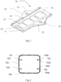
- FIG. 1 shows one embodiment of a tool 10 for assembling a seat in a vehicle.
- This tool 10 comprises a central longitudinal surface 11 with, on either side, two wings 12 provided with stops 13 in the shape of a U, that is to say in the shape of a slot, a hollow or a nook.
- the wings 12 are transverse, that is to say arranged in a direction perpendicular to the longitudinal direction of the tool 10 and of the longitudinal surface 11.
- the stops 13 are longitudinal, that is to say arranged to take support in the longitudinal direction of the tool 10 and the longitudinal surface 11.
- the tool 10 further comprises a proximal recess 14 arranged to serve as a handle, as well as several recesses 15 intended to reduce the weight of the tool 10.
- the stops 13 are intended to cooperate with securing means attached to the vehicle so as to position and secure the tool 10 within the vehicle when assembling a seat to the vehicle.
- the longitudinal surface 11 is intended to accommodate a vehicle seat at least in an intermediate position, that is to say positioned in the vehicle, but not yet assembled or secured to the vehicle.
- the tool 10 is made of any type of rigid material having good mechanical strength and a reduced coefficient of friction.
- the tool 10 is made of polished metal or of a rigid polymer such as polycarbonate or poly(tetrafluoroethylene), which makes it possible to reduce its weight.
- the tool 10 can be made of a first rigid material and comprise on a working surface a second material with a low coefficient of friction to form the longitudinal surface 11.
- FIG. 2 represents a bowl 100 of a vehicle comprising a bottom 101 and side walls 102.
- This bowl 100 can be arranged in a vehicle floor, for example a trunk floor or a passenger compartment floor or on any other surface intended to receive a seat.
- the side walls 102 of the bowl 100 are provided with front securing means 103 and rear securing means 104, along the longitudinal axis of the vehicle. That is to say that the front securing means 103 are located towards the front of the vehicle relative to the rear securing means located towards the rear of the vehicle.
- the securing means 103,104 are identical and have the shape of a trunnion, diabolo or bordered stud. That is, they include a shank or throat 103a, 104a and a tip or head 103b, 104b. These securing means are intended to allow the securing or assembly of a vehicle seat, as explained below.
- a tool 200 is placed in the bowl 100 in a first step of the assembly process.
- This tool 200 comprises a central longitudinal surface 211 as well as two opposite wings 212 each comprising an abutment 213 in the form of a transverse surface, that is to say extending perpendicularly to the longitudinal surface 211, on both sides. other of the longitudinal surface 211.
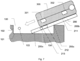
- a front part 200a of the tool 200 (on the top of the picture 3 ) is in contact with the bottom 101 of the bowl 100 while a rear part 200b of the tool 200 (bottom of the picture 3 ) is located outside the bowl 100.
- a middle part 200c rests on the side wall 102 of the bowl 100, and the tool 200 is therefore inclined relative to a horizontal axis and relative to the bottom 101, as seen on the figure 7 .
- the tool is then in an assembly position, suitable for receiving a seat to facilitate assembly or securing to the vehicle.
- a seat 300 is placed in an intermediate position on the rear part 200b of the tool 200, that is to say that the seat 300 is placed on the tool 200 in the vehicle, but can be moved, as explained below.
- This seat 300 includes front attachments 301 capable of cooperating with the front securing means 103 of the bowl 100 and rear securing means 302 capable of cooperating with the rear securing means 104 of the bowl 100.
- these fasteners 301,302 are hooks or slots capable of cooperating with the grooves 103a, 104a of the securing means 103,104.
- the seat In order to assemble the seat 300 in the bowl 100, the seat is moved forwards in a third step by an operator and slides along the longitudinal surface 211 of the tool 200 according to the arrow visible on the figure 4 And 7 . This sliding movement is aided by the weight of the seat 300 and the inclination of the longitudinal surface 211 which then forms a ramp, and only moderate or zero effort is necessary to set the seat 300 in motion. 200 is retained and immobilized by the cooperation between the stops 213 and the rear securing means 104 and is not driven to the bottom of the bowl 100.
- the seat 300 has slid along the longitudinal surface 211 of the tool 200 and now covers the front part 200a of the tool 200, which is then not visible.
- the seat 300 is then in a docking position, that is to say that its rear attachments 302 are located close to the rear securing means 104 of the bowl 100 without being able to engage them, due to the presence of the wings 212 and/or stops 213 of tool 200.
- the front attachments 301 of the seat have engaged or clipped the front securing means 103 at the end of the sliding movement and the seat is therefore already partially attached or secured to the bowl 100.
- the tool 200 is then grasped by the operator by the proximal recess 214 serving as a handle and pulled backwards according to the arrow visible on the figure 5 , according to a fourth step of the assembly process.
- the longitudinal surface 211 therefore slides under the seat 300 which is not driven due to the engagement between the front attachments 301 and the front securing means 103 of the bowl 100.
- the wings 212 and the stops 213 are disengaged rear securing means 104 and then allow the seat to fall or pivot towards the bottom of the cavity 100 by a downward movement of its rear part.
- the movement of the seat is therefore generally a rotational movement towards the bottom 101 around the front attachments 301.
- the rear attachments 302 of the seat engage or clip the rear securing means 104, in a passive manner, i.e. that is to say without any other movement than releasing the tool 200 and the seat 300 is now assembled or secured to the bowl 100 and therefore to the vehicle, as shown in the figure 6 .
- the securing means 103,104, the seat 300 and the tool 200 form a system or an assembly making it possible to assemble the seat 300 to the vehicle.
Landscapes
- Engineering & Computer Science (AREA)
- Mechanical Engineering (AREA)
- Aviation & Aerospace Engineering (AREA)
- Transportation (AREA)
- Seats For Vehicles (AREA)
Description
- La présente invention concerne de manière générale un outil pour l'assemblage d'un siège dans un véhicule. En outre, la présente invention concerne un système pour l'assemblage d'un siège dans un véhicule ainsi qu'un procédé d'assemblage d'un siège dans un véhicule.
- Il est connu dans l'art antérieur des sièges de véhicule, et notamment des sièges de véhicule amovibles et escamotables. Ainsi, le document
FR3001926 - En contrepartie, aucun dispositif ou procédé n'existe pour faciliter l'assemblage d'un tel siège en usine lors de la fabrication du véhicule. Il est ainsi nécessaire d'assembler manuellement chaque siège au véhicule par un opérateur sans aucune assistance, ce qui nécessite un certain temps et consiste en une succession d'opérations peu ergonomiques pour l'opérateur.
- Un but de la présente invention est de répondre aux inconvénients du document de l'art antérieur mentionnés ci-dessus et en particulier, de proposer un outil pour faciliter l'assemblage d'un siège dans un véhicule ainsi qu'un procédé simplifié d'assemblage, permettant de réduire le temps de fabrication et de simplifier la tâche de l'opérateur en la rendant plus simple et/ou plus ergonomique.
- Pour cela un premier aspect de l'invention concerne un outil pour l'assemblage d'un siège dans un véhicule selon la revendication 1. Une telle configuration de l'outil permet une stabilité optimale quand l'outil est en position d'assemblage dans le véhicule. De plus la poignée permet donc à un opérateur de tirer l'outil afin de le dégager de sa position d'assemblage et donc permettre l'arrimage du siège au moyen d'arrimage.
- Un tel outil permet de réaliser efficacement l'assemblage d'un siège à un véhicule, c'est-à-dire rapidement, sans risque de mauvais assemblage et sans difficulté ergonomique pour l'opérateur. En effet, la rampe permettant de faire coulisser le siège évite notamment à l'opérateur de soulever le siège.
- Un second aspect de l'invention est un système pour l'assemblage d'un siège dans un véhicule selon la revendication 3.
- Avantageusement, le système comprend, selon un axe longitudinal du véhicule, un moyen d'arrimage avant et deux moyens d'arrimage arrière, et ledit outil dans la position d'assemblage un outil selon le premier aspect de l'invention, le système comprenant selon un axe longitudinal du véhicule, un moyen d'arrimage avant et un moyen d'arrimage arrière, et ledit outil dans la position d'assemblage est positionné avec les butées avec les moyens d'arrimage arrière pour immobiliser ledit outil. L'outil est donc stable dans la position d'assemblage et ne peut donc pas être soumis à des mouvements involontaires préjudiciables à l'assemblage correct du siège.
- Avantageusement, le siège dans la position d'accostage est arrimé au moyen d'arrimage avant et à proximité du moyen d'arrimage arrière, donc non arrimé au moyen d'arrimage arrière. Ceci afin de retenir le siège lorsque l'outil est dégagé et permettre alors l'assemblage au moyen d'arrimage arrière par gravité, c'est-à-dire par un mouvement de l'arrière du siège vers le bas de façon à engager le moyen d'arrimage arrière.
- Un dernier aspect de l'invention est un procédé d'assemblage d'un siège dans un véhicule selon la revendication 6.
- On entend par « position intermédiaire » du siège une position dans laquelle le siège est posé sur l'outil à l'intérieur du véhicule, par exemple sur le seuil de coffre quand le siège prend place dans un coffre de véhicule. De plus, on entend par « position d'accostage » du siège une position dans laquelle les attaches arrière du siège sont situées à proximité des moyens d'arrimage arrière sans pouvoir les engager du fait de la présence de l'outil.
- D'autres caractéristiques et avantages de la présente invention apparaîtront plus clairement à la lecture de la description détaillée qui suit d'un mode de réalisation de l'invention donné à titre d'exemple nullement limitatif et illustré par les dessins annexés, dans lesquels :
- la
figure 1 représente un outil pour l'assemblage d'un siège dans un véhicule selon la présente invention. - les
figures 2 à 6 représentent les étapes, vues de dessus, d'un procédé d'assemblage d'un siège dans un véhicule utilisant un outil selon la présente invention, - la
figure 7 représente l'étape du procédé montrée à lafigure 4 en vue latérale. - L'invention concerne de manière générale un outil pour l'assemblage de tout type de siège de véhicule et un procédé pour effectuer un tel assemblage. Par exemple, il peut s'agir d'un siège amovible et escamotable d'une troisième rangée de sièges dans un véhicule de type monospace ou véhicule utilitaire de sport (SUV). Cependant, il peut s'agir de tout autre type de siège, par exemple conducteur ou passager, amovible, escamotable ou non. En outre, un tel siège peut être assemblé à tout type de véhicule tel qu'un véhicule individuel, collectif ou utilitaire.
- Dans la présente description, les termes « avant » et « arrière » ont toujours pour référence l'axe longitudinal ou de direction du véhicule et un élément « avant » est donc situé vers l'avant du véhicule, c'est-à-dire vers le siège conducteur du véhicule.
- La
figure 1 représente un mode de réalisation d'un outil 10 pour l'assemblage d'un siège dans un véhicule. Cet outil 10 comprend une surface longitudinale 11 centrale avec de part et d'autre deux ailes 12 munies de butées 13 en forme de U, c'est-à-dire en forme de fente, de creux ou de recoin. Les ailes 12 sont transversales, c'est-à-dire agencées dans une direction perpendiculaire à la direction longitudinale de l'outil 10 et de la surface longitudinale 11. Les butées 13 sont longitudinales, c'est-à-dire agencées pour prendre appui dans la direction longitudinale de l'outil 10 et de la surface longitudinale 11. L'outil 10 comprend de plus un évidement 14 proximal agencé pour servir de poignée, ainsi que plusieurs évidements 15 destinés à réduire le poids de l'outil 10. - Comme expliqué ci-après, les butées 13 sont destinées à coopérer avec des moyens d'arrimage attachés au véhicule de telle sorte à positionner et sécuriser l'outil 10 au sein du véhicule lors de l'assemblage d'un siège au véhicule. De plus, la surface longitudinale 11 est destinée à accueillir un siège de véhicule au moins dans une position intermédiaire, c'est-à-dire positionné dans le véhicule, mais non encore assemblé ou arrimé au véhicule.
- L'outil 10 est fabriqué dans tout type de matériau rigide présentant une bonne résistance mécanique et un coefficient de frottement réduit. Par exemple, l'outil 10 est fabriqué en métal poli ou en polymère rigide comme le polycarbonate ou le poly(tétrafluoroethylène), ce qui permet de réduire son poids. En outre l'outil 10 peut être fabriqué dans un premier matériau rigide et comprendre sur une surface de travail un deuxième matériau à faible coefficient de frottement pour former la surface longitudinale 11.
- En référence aux
figures 2 à 7 , est décrit un procédé d'assemblage d'un siège à un véhicule utilisant un outil 200 selon une représentation schématique de l'outil 10 en référence à lafigure 1 . - La
figure 2 représente une cuvette 100 d'un véhicule comprenant un fond 101 et des parois latérales 102. Cette cuvette 100 peut être aménagée dans un plancher de véhicule, par exemple un plancher de coffre ou un plancher d'habitacle ou sur tout autre surface destinée à recevoir un siège. Les parois latérales 102 de la cuvette 100 sont munies de moyens d'arrimage avant 103 et de moyens d'arrimage arrière 104, selon l'axe longitudinal du véhicule. C'est-à-dire que les moyens d'arrimage avant 103 sont situés vers l'avant du véhicule par rapport aux moyens d'arrimage arrière situés vers l'arrière du véhicule. - Les moyens d'arrimage 103,104 sont identiques et ont une forme de tourillon, diabolo ou plot bordé. C'est-à-dire qu'ils comprennent une tige ou gorge 103a, 104a et un bout ou une tête 103b,104b. Ces moyens d'arrimage sont destinés à permettre l'arrimage ou l'assemblage d'un siège de véhicule, comme expliqué ci-après.
- Ainsi, sur la
figure 3 , un outil 200 est placé dans la cuvette 100 dans une première étape du procédé d'assemblage. Cet outil 200 comprend une surface longitudinale 211 centrale ainsi que deux ailes 212 opposées comprenant chacune une butée 213 sous la forme d'une surface transversale, c'est-à-dire s'étendant perpendiculairement à la surface longitudinale 211, de part et d'autre de la surface longitudinale 211. - Sur la
figure 3 , une partie avant 200a de l'outil 200 (sur le haut de lafigure 3 ) est en contact avec le fond 101 de la cuvette 100 alors qu'une partie arrière 200b de l'outil 200 (bas de lafigure 3 ) est située en dehors de la cuvette 100. Ainsi, une partie médiane 200c est en appui sur la paroi latérale 102 de la cuvette 100, et l'outil 200 est donc incliné par rapport à un axe horizontal et par rapport au fond 101, comme visible sur lafigure 7 . L'outil est alors dans une position d'assemblage, apte à recevoir un siège pour en faciliter l'assemblage ou l'arrimage au véhicule. - Sur les
figures 4 et7 , dans une deuxième étape, un siège 300 est déposé dans une position intermédiaire sur la partie arrière 200b de l'outil 200, c'est-à-dire que le siège 300 est posé sur l'outil 200 dans le véhicule, mais peut être déplacé, comme expliqué ci-après. Ce siège 300 comprend des attaches avant 301 aptes à coopérer avec les moyens d'arrimage avant 103 de la cuvette 100 et des moyens d'arrimage arrière 302 aptes à coopérer avec les moyens d'arrimage arrière 104 de la cuvette 100. Par exemple, ces attaches 301,302 sont des crochets ou des fentes aptes à coopérer avec les gorges 103a, 104a des moyens d'arrimage 103,104. - Afin d'assembler le siège 300 dans la cuvette 100, le siège est mis en mouvement vers l'avant dans une troisième étape par un opérateur et coulisse le long de la surface longitudinale 211 de l'outil 200 selon la flèche visible sur les
figures 4 et7 . Ce mouvement de coulissement est aidé par le poids du siège 300 et l'inclinaison de la surface longitudinale 211 qui forme alors une rampe, et seul un effort modéré ou nul est nécessaire pour mettre en mouvement le siège 300. En outre, l'outil 200 est retenu et immobilisé par la coopération entre les butées 213 et les moyens d'arrimage arrière 104 et n'est pas entrainé au fond de la cuvette 100. - Sur la
figure 5 , le siège 300 a coulissé le long de la surface longitudinale 211 de l'outil 200 et recouvre désormais la partie avant 200a de l'outil 200, qui est alors non visible. Le siège 300 est alors dans une position d'accostage, c'est-à-dire que ses attaches arrière 302 sont situées à proximité des moyens d'arrimage arrière 104 de la cuvette 100 sans pouvoir les engager, du fait de la présence des ailes 212 et/ou des butées 213 de l'outil 200. Par ailleurs, les attaches avant 301 du siège ont engagé ou enclipsé les moyens d'arrimage avant 103 à la fin du mouvement de coulissement et le siège est donc déjà partiellement attaché ou arrimé à la cuvette 100. - L'outil 200 est alors saisi par l'opérateur par l'évidement proximal 214 servant de poignée et tiré vers l'arrière selon la flèche visible sur la
figure 5 , selon une quatrième étape du procédé d'assemblage. La surface longitudinale 211 coulisse donc sous le siège 300 qui n'est pas entrainé du fait de l'engagement entre les attaches avant 301 et les moyens d'arrimage avant 103 de la cuvette 100. De plus, les ailes 212 et les butées 213 sont désengagées des moyens d'arrimage arrière 104 et permettent alors au siège de tomber ou pivoter vers le fond de la cavité 100 par un mouvement vers le bas de sa partie arrière. Le mouvement du siège est donc globalement un mouvement de rotation vers le fond 101 autour des attaches avant 301. Durant ce mouvement, les attaches arrière 302 du siège engagent ou enclipsent les moyens d'arrimage arrière 104, de façon passive, c'est-à-dire sans autre mouvement que de dégager l'outil 200 et le siège 300 est désormais assemblé ou arrimé à la cuvette 100 et donc au véhicule, comme représenté sur lafigure 6 . - Ainsi, les moyens d'arrimage 103,104, le siège 300 et l'outil 200 forment un système ou un ensemble permettant d'assembler le siège 300 au véhicule.
- On comprendra que diverses modifications et/ou améliorations évidentes pour l'homme du métier peuvent être apportées aux différents modes de réalisation de l'invention décrits dans la présente description sans sortir du cadre de l'invention. En particulier, il est fait référence aux moyens d'arrimage 103, 104, et aux attaches 301,302 du siège 300 qui peuvent prendre tout type de formes complémentaires, par exemple boucle-crochet ou pêne-gâche, de même pour les butées 13,213. En outre, le nombre de moyens d'arrimage, d'attaches et de butées n'est pas limité aux exemples des
figures 1 à 6 et peut comprendre tout nombre nécessaire.
Claims (8)
- Outil (10, 200) d'assemblage d'un siège (300) dans un véhicule comprenant au moins deux moyens d'arrimage (104) pour fixer ledit siège (300) au véhicule, ledit outil (10, 200) comprenant :• au moins une surface longitudinale (11, 211) centrale |0022] agencée pour accueillir ledit siège (300) dans une position intermédiaire et une position d'accostage, la surface longitudinale (11, 211) de l'outil en position d'assemblage formant une rampe de sorte à guider le siège (300) depuis la position intermédiaire vers la position d'accostage du siège (300) avec ledit moyen d'arrimage (104),• la surface longitudinale comportant au moins deux ailes transversales comprenant chacune une butée (13, 213) longitudinale en forme de U agencée pour coopérer avec un desdits moyens d'arrimage (104) afin d'immobiliser ledit outil (10,200) dans une position d'assemblage, les deux butées (13, 213) étant situées de part et d'autre de la surface longitudinale (13, 213).
- Outil (10,200) selon la revendication précédente, caractérisé en ce que la surface longitudinale (11,211) est pourvue d'une poignée agencée pour faciliter le dégagement de l'outil (10,200) de l'espace entre le siège (300) et le moyen d'arrimage (104).
- Système pour l'assemblage d'un siège dans un véhicule, le système comprenant :• au moins deux moyens d'arrimage (103,104) pour fixer ledit siège (300) au véhicule,• au moins un siège (300) agencé pour s'arrimer aux-dit moyens d'arrimage (103,104),• un outil (10,200) selon l'une quelconque des revendications précédentes.
- Système selon la revendication précédente, caractérisé en ce qu'il comprend, selon un axe longitudinal du véhicule,- un moyen d'arrimage avant (103) et deux moyens d'arrimage arrière (104),- et dans lequel ledit outil (10,200) dans la position d'assemblage est positionné avec les butées (13, 213) coopérant avec les moyens d'arrimage arrière (104) pour immobiliser ledit outil.
- Système selon la revendication précédente, dans lequel le siège (300) dans la position d'accostage est arrimé au moyen d'arrimage avant (103) et se situe à proximité des moyens d'arrimage arrière (104).
- Procédé d'assemblage d'un siège (300) dans un véhicule, ledit véhicule comprenant au moins deux moyens d'arrimage (104) pour le siège (300), ledit procédé comprenant les étapes consistant à :• mettre en appui sur lesdits moyens d'arrimage (104) chacune des butées (13,213) d'un outil (10,200) selon l'une des revendications 1 à 2 pour immobiliser ledit outil (10,200) dans une position d'assemblage,• positionner un siège (300) dans une position intermédiaire sur ladite surface longitudinale (11,211) dudit outil (10,200),• faire coulisser le siège (300) le long de la surface longitudinale (11, 211) jusqu'à une position d'accostage dans laquelle le siège (300) se situe à proximité dudit moyen d'arrimage (104),• dégager l'outil (10,200) de l'espace entre le siège (300) et le moyen d'arrimage (104),• arrimer le siège (300) aux moyens d'arrimage (104).
- Procédé selon la revendication précédente, dans lequel le véhicule comprend, selon un axe longitudinal, un moyen d'arrimage avant (103) et deux moyens d'arrimage arrière (104), et dans lequel ledit outil (10,200) dans la position d'assemblage est positionné avec les butées (13,213) coopérant avec les moyens d'arrimage arrière (104) pour immobiliser ledit outil (10,200).
- Procédé selon la revendication précédente, dans lequel le siège (300) dans la position d'accostage est arrimé au moyen d'arrimage avant (103) et est disposé à proximité du moyen d'arrimage arrière (104).
Applications Claiming Priority (2)
| Application Number | Priority Date | Filing Date | Title |
|---|---|---|---|
| FR1751822A FR3063665B1 (fr) | 2017-03-07 | 2017-03-07 | Outil pour l’assemblage d’un siege dans un vehicule. |
| PCT/FR2018/050350 WO2018162814A1 (fr) | 2017-03-07 | 2018-02-13 | Outil pour l'assemblage d'un siège dans un véhicule |
Publications (2)
| Publication Number | Publication Date |
|---|---|
| EP3592506A1 EP3592506A1 (fr) | 2020-01-15 |
| EP3592506B1 true EP3592506B1 (fr) | 2023-09-06 |
Family
ID=58739161
Family Applications (1)
| Application Number | Title | Priority Date | Filing Date |
|---|---|---|---|
| EP18707950.4A Active EP3592506B1 (fr) | 2017-03-07 | 2018-02-13 | Outil pour l'assemblage d'un siège dans un véhicule |
Country Status (5)
| Country | Link |
|---|---|
| EP (1) | EP3592506B1 (fr) |
| FR (1) | FR3063665B1 (fr) |
| MA (1) | MA47726A (fr) |
| MY (1) | MY201691A (fr) |
| WO (1) | WO2018162814A1 (fr) |
Families Citing this family (1)
| Publication number | Priority date | Publication date | Assignee | Title |
|---|---|---|---|---|
| CN115091402B (zh) * | 2022-07-29 | 2024-03-26 | 广域铭岛数字科技有限公司 | 一种装配岛的产品装配方法 |
Family Cites Families (4)
| Publication number | Priority date | Publication date | Assignee | Title |
|---|---|---|---|---|
| WO2007083203A2 (fr) * | 2005-12-14 | 2007-07-26 | Smit, Carel, Christiaan | Joints de tuyaux |
| FR2967947B1 (fr) * | 2010-11-25 | 2012-11-16 | Peugeot Citroen Automobiles Sa | Dispositif de fixation a paroi de retenue transversale, pour un fil de gache d'une assise de siege de vehicule |
| FR3001926B1 (fr) | 2013-02-13 | 2015-02-27 | Peugeot Citroen Automobiles Sa | Arrimage de siege amovible et escamotable a un plancher de vehicule |
| FR3021001B1 (fr) * | 2014-05-14 | 2017-11-24 | Renault Sas | Vehicule automobile comportant des supports de siege retractables |
-
2017
- 2017-03-07 FR FR1751822A patent/FR3063665B1/fr not_active Expired - Fee Related
-
2018
- 2018-02-13 WO PCT/FR2018/050350 patent/WO2018162814A1/fr not_active Ceased
- 2018-02-13 MY MYPI2019005123A patent/MY201691A/en unknown
- 2018-02-13 EP EP18707950.4A patent/EP3592506B1/fr active Active
- 2018-02-13 MA MA047726A patent/MA47726A/fr unknown
Also Published As
| Publication number | Publication date |
|---|---|
| EP3592506A1 (fr) | 2020-01-15 |
| FR3063665B1 (fr) | 2019-03-29 |
| FR3063665A1 (fr) | 2018-09-14 |
| MY201691A (en) | 2024-03-13 |
| WO2018162814A1 (fr) | 2018-09-13 |
| MA47726A (fr) | 2020-01-15 |
Similar Documents
| Publication | Publication Date | Title |
|---|---|---|
| FR2825955A1 (fr) | Mecanisme d'articulation de siege de vehicule ameliore | |
| EP3060428B1 (fr) | Dispositif de blocage en position d'un element rabattable pour un siege de vehicule | |
| FR2929899A1 (fr) | Console centrale | |
| FR2938479A1 (fr) | Dispositif de masquage arriere de vehicule automobile et ensemble arriere associe | |
| FR3083174A1 (fr) | Siege de vehicule automobile | |
| FR2815307A1 (fr) | Console coulissante sur rails, notamment pour automobile | |
| EP3496974B1 (fr) | Ensemble coulissant pour habitacle de vehicule automobile a confort d'utilisation ameliore | |
| EP3592506B1 (fr) | Outil pour l'assemblage d'un siège dans un véhicule | |
| EP3197722B1 (fr) | Agencement d'un plancher a l'interieur d'un coffre de vehicule automobile comportant des sieges escamotables | |
| EP3063035B1 (fr) | Siège escamotable pour véhicule | |
| EP3131783B1 (fr) | Véhicule automobile équipe d'une banquette arrière allégée | |
| EP3350016B1 (fr) | Dispositif de verrouillage bi-positions d'un dossier de siege arriere de vehicule automobile | |
| EP3738832B1 (fr) | Support interne d'objet débrayable pour véhicule automobile | |
| FR2920361A1 (fr) | Actionneur de deverrouillage de siege a logement de guidage et d'extraction de ceinture de securite, et dispositif de deverrouillage et siege correspondants. | |
| FR3062608A1 (fr) | Dispositif de verrouillage reversible a palonnier de la position longitudinale d'un siege et ensemble de siege le comprenant | |
| FR2829976A1 (fr) | Dispositif a tablette rabattable pour vehicule automobile et siege comportant un tel dispositif | |
| FR3054500B1 (fr) | Console centrale de vehicule comprenant un accoudoir et un support de rangement | |
| FR3062609A1 (fr) | Dispositif de verrouillage reversible a palonnier de la position longitudinale d'un siege et ensemble de siege le comprenant | |
| FR3061880A1 (fr) | Porte-articles de vehicule a barres transversales a basculement en position et escamotables | |
| FR3043955A1 (fr) | Siege mobile pour vehicule automobile | |
| FR2936747A1 (fr) | Siege pour vehicule automobile | |
| EP4321384A1 (fr) | Porte-charge d'un véhicule automobile | |
| FR3058103A1 (fr) | Mecanisme de reglage, siege de vehicule comprenant un tel mecanisme et procede de montage d'un tel mecanisme | |
| FR3142138A1 (fr) | Dispositif de préhension comprenant une poignée amovible pour un véhicule | |
| FR2886592A1 (fr) | Agencement de sieges dans un vehicule automobile |
Legal Events
| Date | Code | Title | Description |
|---|---|---|---|
| STAA | Information on the status of an ep patent application or granted ep patent |
Free format text: STATUS: UNKNOWN |
|
| STAA | Information on the status of an ep patent application or granted ep patent |
Free format text: STATUS: THE INTERNATIONAL PUBLICATION HAS BEEN MADE |
|
| PUAI | Public reference made under article 153(3) epc to a published international application that has entered the european phase |
Free format text: ORIGINAL CODE: 0009012 |
|
| STAA | Information on the status of an ep patent application or granted ep patent |
Free format text: STATUS: REQUEST FOR EXAMINATION WAS MADE |
|
| 17P | Request for examination filed |
Effective date: 20190821 |
|
| AK | Designated contracting states |
Kind code of ref document: A1 Designated state(s): AL AT BE BG CH CY CZ DE DK EE ES FI FR GB GR HR HU IE IS IT LI LT LU LV MC MK MT NL NO PL PT RO RS SE SI SK SM TR |
|
| AX | Request for extension of the european patent |
Extension state: BA ME |
|
| DAX | Request for extension of the european patent (deleted) | ||
| RAV | Requested validation state of the european patent: fee paid |
Extension state: MA Effective date: 20190821 |
|
| RAP1 | Party data changed (applicant data changed or rights of an application transferred) |
Owner name: PSA AUTOMOBILES SA |
|
| STAA | Information on the status of an ep patent application or granted ep patent |
Free format text: STATUS: EXAMINATION IS IN PROGRESS |
|
| 17Q | First examination report despatched |
Effective date: 20211105 |
|
| GRAP | Despatch of communication of intention to grant a patent |
Free format text: ORIGINAL CODE: EPIDOSNIGR1 |
|
| STAA | Information on the status of an ep patent application or granted ep patent |
Free format text: STATUS: GRANT OF PATENT IS INTENDED |
|
| INTG | Intention to grant announced |
Effective date: 20230515 |
|
| GRAS | Grant fee paid |
Free format text: ORIGINAL CODE: EPIDOSNIGR3 |
|
| GRAA | (expected) grant |
Free format text: ORIGINAL CODE: 0009210 |
|
| STAA | Information on the status of an ep patent application or granted ep patent |
Free format text: STATUS: THE PATENT HAS BEEN GRANTED |
|
| AK | Designated contracting states |
Kind code of ref document: B1 Designated state(s): AL AT BE BG CH CY CZ DE DK EE ES FI FR GB GR HR HU IE IS IT LI LT LU LV MC MK MT NL NO PL PT RO RS SE SI SK SM TR |
|
| REG | Reference to a national code |
Ref country code: GB Ref legal event code: FG4D Free format text: NOT ENGLISH |
|
| REG | Reference to a national code |
Ref country code: DE Ref legal event code: R084 Ref document number: 602018056922 Country of ref document: DE |
|
| REG | Reference to a national code |
Ref country code: CH Ref legal event code: EP |
|
| REG | Reference to a national code |
Ref country code: DE Ref legal event code: R096 Ref document number: 602018056922 Country of ref document: DE |
|
| REG | Reference to a national code |
Ref country code: IE Ref legal event code: FG4D Free format text: LANGUAGE OF EP DOCUMENT: FRENCH |
|
| REG | Reference to a national code |
Ref country code: GB Ref legal event code: 746 Effective date: 20231004 |
|
| RAP4 | Party data changed (patent owner data changed or rights of a patent transferred) |
Owner name: STELLANTIS AUTO SAS |
|
| REG | Reference to a national code |
Ref country code: LT Ref legal event code: MG9D |
|
| REG | Reference to a national code |
Ref country code: NL Ref legal event code: MP Effective date: 20230906 |
|
| PG25 | Lapsed in a contracting state [announced via postgrant information from national office to epo] |
Ref country code: GR Free format text: LAPSE BECAUSE OF FAILURE TO SUBMIT A TRANSLATION OF THE DESCRIPTION OR TO PAY THE FEE WITHIN THE PRESCRIBED TIME-LIMIT Effective date: 20231207 |
|
| PG25 | Lapsed in a contracting state [announced via postgrant information from national office to epo] |
Ref country code: SE Free format text: LAPSE BECAUSE OF FAILURE TO SUBMIT A TRANSLATION OF THE DESCRIPTION OR TO PAY THE FEE WITHIN THE PRESCRIBED TIME-LIMIT Effective date: 20230906 Ref country code: RS Free format text: LAPSE BECAUSE OF FAILURE TO SUBMIT A TRANSLATION OF THE DESCRIPTION OR TO PAY THE FEE WITHIN THE PRESCRIBED TIME-LIMIT Effective date: 20230906 Ref country code: NO Free format text: LAPSE BECAUSE OF FAILURE TO SUBMIT A TRANSLATION OF THE DESCRIPTION OR TO PAY THE FEE WITHIN THE PRESCRIBED TIME-LIMIT Effective date: 20231206 Ref country code: LV Free format text: LAPSE BECAUSE OF FAILURE TO SUBMIT A TRANSLATION OF THE DESCRIPTION OR TO PAY THE FEE WITHIN THE PRESCRIBED TIME-LIMIT Effective date: 20230906 Ref country code: LT Free format text: LAPSE BECAUSE OF FAILURE TO SUBMIT A TRANSLATION OF THE DESCRIPTION OR TO PAY THE FEE WITHIN THE PRESCRIBED TIME-LIMIT Effective date: 20230906 Ref country code: HR Free format text: LAPSE BECAUSE OF FAILURE TO SUBMIT A TRANSLATION OF THE DESCRIPTION OR TO PAY THE FEE WITHIN THE PRESCRIBED TIME-LIMIT Effective date: 20230906 Ref country code: GR Free format text: LAPSE BECAUSE OF FAILURE TO SUBMIT A TRANSLATION OF THE DESCRIPTION OR TO PAY THE FEE WITHIN THE PRESCRIBED TIME-LIMIT Effective date: 20231207 Ref country code: FI Free format text: LAPSE BECAUSE OF FAILURE TO SUBMIT A TRANSLATION OF THE DESCRIPTION OR TO PAY THE FEE WITHIN THE PRESCRIBED TIME-LIMIT Effective date: 20230906 |
|
| REG | Reference to a national code |
Ref country code: AT Ref legal event code: MK05 Ref document number: 1607873 Country of ref document: AT Kind code of ref document: T Effective date: 20230906 |
|
| PG25 | Lapsed in a contracting state [announced via postgrant information from national office to epo] |
Ref country code: NL Free format text: LAPSE BECAUSE OF FAILURE TO SUBMIT A TRANSLATION OF THE DESCRIPTION OR TO PAY THE FEE WITHIN THE PRESCRIBED TIME-LIMIT Effective date: 20230906 |
|
| PG25 | Lapsed in a contracting state [announced via postgrant information from national office to epo] |
Ref country code: IS Free format text: LAPSE BECAUSE OF FAILURE TO SUBMIT A TRANSLATION OF THE DESCRIPTION OR TO PAY THE FEE WITHIN THE PRESCRIBED TIME-LIMIT Effective date: 20240106 |
|
| REG | Reference to a national code |
Ref country code: DE Ref legal event code: R081 Ref document number: 602018056922 Country of ref document: DE Owner name: STELLANTIS AUTO SAS, FR Free format text: FORMER OWNER: PSA AUTOMOBILES SA, POISSY, FR |
|
| PG25 | Lapsed in a contracting state [announced via postgrant information from national office to epo] |
Ref country code: AT Free format text: LAPSE BECAUSE OF FAILURE TO SUBMIT A TRANSLATION OF THE DESCRIPTION OR TO PAY THE FEE WITHIN THE PRESCRIBED TIME-LIMIT Effective date: 20230906 |
|
| PG25 | Lapsed in a contracting state [announced via postgrant information from national office to epo] |
Ref country code: ES Free format text: LAPSE BECAUSE OF FAILURE TO SUBMIT A TRANSLATION OF THE DESCRIPTION OR TO PAY THE FEE WITHIN THE PRESCRIBED TIME-LIMIT Effective date: 20230906 |
|
| PG25 | Lapsed in a contracting state [announced via postgrant information from national office to epo] |
Ref country code: SM Free format text: LAPSE BECAUSE OF FAILURE TO SUBMIT A TRANSLATION OF THE DESCRIPTION OR TO PAY THE FEE WITHIN THE PRESCRIBED TIME-LIMIT Effective date: 20230906 Ref country code: RO Free format text: LAPSE BECAUSE OF FAILURE TO SUBMIT A TRANSLATION OF THE DESCRIPTION OR TO PAY THE FEE WITHIN THE PRESCRIBED TIME-LIMIT Effective date: 20230906 Ref country code: IS Free format text: LAPSE BECAUSE OF FAILURE TO SUBMIT A TRANSLATION OF THE DESCRIPTION OR TO PAY THE FEE WITHIN THE PRESCRIBED TIME-LIMIT Effective date: 20240106 Ref country code: ES Free format text: LAPSE BECAUSE OF FAILURE TO SUBMIT A TRANSLATION OF THE DESCRIPTION OR TO PAY THE FEE WITHIN THE PRESCRIBED TIME-LIMIT Effective date: 20230906 Ref country code: EE Free format text: LAPSE BECAUSE OF FAILURE TO SUBMIT A TRANSLATION OF THE DESCRIPTION OR TO PAY THE FEE WITHIN THE PRESCRIBED TIME-LIMIT Effective date: 20230906 Ref country code: CZ Free format text: LAPSE BECAUSE OF FAILURE TO SUBMIT A TRANSLATION OF THE DESCRIPTION OR TO PAY THE FEE WITHIN THE PRESCRIBED TIME-LIMIT Effective date: 20230906 Ref country code: AT Free format text: LAPSE BECAUSE OF FAILURE TO SUBMIT A TRANSLATION OF THE DESCRIPTION OR TO PAY THE FEE WITHIN THE PRESCRIBED TIME-LIMIT Effective date: 20230906 Ref country code: SK Free format text: LAPSE BECAUSE OF FAILURE TO SUBMIT A TRANSLATION OF THE DESCRIPTION OR TO PAY THE FEE WITHIN THE PRESCRIBED TIME-LIMIT Effective date: 20230906 Ref country code: PT Free format text: LAPSE BECAUSE OF FAILURE TO SUBMIT A TRANSLATION OF THE DESCRIPTION OR TO PAY THE FEE WITHIN THE PRESCRIBED TIME-LIMIT Effective date: 20240108 |
|
| PG25 | Lapsed in a contracting state [announced via postgrant information from national office to epo] |
Ref country code: PL Free format text: LAPSE BECAUSE OF FAILURE TO SUBMIT A TRANSLATION OF THE DESCRIPTION OR TO PAY THE FEE WITHIN THE PRESCRIBED TIME-LIMIT Effective date: 20230906 Ref country code: IT Free format text: LAPSE BECAUSE OF FAILURE TO SUBMIT A TRANSLATION OF THE DESCRIPTION OR TO PAY THE FEE WITHIN THE PRESCRIBED TIME-LIMIT Effective date: 20230906 |
|
| REG | Reference to a national code |
Ref country code: DE Ref legal event code: R097 Ref document number: 602018056922 Country of ref document: DE |
|
| PG25 | Lapsed in a contracting state [announced via postgrant information from national office to epo] |
Ref country code: DK Free format text: LAPSE BECAUSE OF FAILURE TO SUBMIT A TRANSLATION OF THE DESCRIPTION OR TO PAY THE FEE WITHIN THE PRESCRIBED TIME-LIMIT Effective date: 20230906 |
|
| PLBE | No opposition filed within time limit |
Free format text: ORIGINAL CODE: 0009261 |
|
| STAA | Information on the status of an ep patent application or granted ep patent |
Free format text: STATUS: NO OPPOSITION FILED WITHIN TIME LIMIT |
|
| PG25 | Lapsed in a contracting state [announced via postgrant information from national office to epo] |
Ref country code: DK Free format text: LAPSE BECAUSE OF FAILURE TO SUBMIT A TRANSLATION OF THE DESCRIPTION OR TO PAY THE FEE WITHIN THE PRESCRIBED TIME-LIMIT Effective date: 20230906 Ref country code: SI Free format text: LAPSE BECAUSE OF FAILURE TO SUBMIT A TRANSLATION OF THE DESCRIPTION OR TO PAY THE FEE WITHIN THE PRESCRIBED TIME-LIMIT Effective date: 20230906 |
|
| 26N | No opposition filed |
Effective date: 20240607 |
|
| PG25 | Lapsed in a contracting state [announced via postgrant information from national office to epo] |
Ref country code: MC Free format text: LAPSE BECAUSE OF FAILURE TO SUBMIT A TRANSLATION OF THE DESCRIPTION OR TO PAY THE FEE WITHIN THE PRESCRIBED TIME-LIMIT Effective date: 20230906 |
|
| REG | Reference to a national code |
Ref country code: CH Ref legal event code: PL |
|
| PG25 | Lapsed in a contracting state [announced via postgrant information from national office to epo] |
Ref country code: LU Free format text: LAPSE BECAUSE OF NON-PAYMENT OF DUE FEES Effective date: 20240213 |
|
| PG25 | Lapsed in a contracting state [announced via postgrant information from national office to epo] |
Ref country code: CH Free format text: LAPSE BECAUSE OF NON-PAYMENT OF DUE FEES Effective date: 20240229 |
|
| PG25 | Lapsed in a contracting state [announced via postgrant information from national office to epo] |
Ref country code: LU Free format text: LAPSE BECAUSE OF NON-PAYMENT OF DUE FEES Effective date: 20240213 Ref country code: CH Free format text: LAPSE BECAUSE OF NON-PAYMENT OF DUE FEES Effective date: 20240229 |
|
| PG25 | Lapsed in a contracting state [announced via postgrant information from national office to epo] |
Ref country code: BG Free format text: LAPSE BECAUSE OF FAILURE TO SUBMIT A TRANSLATION OF THE DESCRIPTION OR TO PAY THE FEE WITHIN THE PRESCRIBED TIME-LIMIT Effective date: 20230906 |
|
| PG25 | Lapsed in a contracting state [announced via postgrant information from national office to epo] |
Ref country code: BG Free format text: LAPSE BECAUSE OF FAILURE TO SUBMIT A TRANSLATION OF THE DESCRIPTION OR TO PAY THE FEE WITHIN THE PRESCRIBED TIME-LIMIT Effective date: 20230906 |
|
| REG | Reference to a national code |
Ref country code: BE Ref legal event code: MM Effective date: 20240229 |
|
| PG25 | Lapsed in a contracting state [announced via postgrant information from national office to epo] |
Ref country code: BE Free format text: LAPSE BECAUSE OF NON-PAYMENT OF DUE FEES Effective date: 20240229 |
|
| PG25 | Lapsed in a contracting state [announced via postgrant information from national office to epo] |
Ref country code: IE Free format text: LAPSE BECAUSE OF NON-PAYMENT OF DUE FEES Effective date: 20240213 |
|
| PG25 | Lapsed in a contracting state [announced via postgrant information from national office to epo] |
Ref country code: IE Free format text: LAPSE BECAUSE OF NON-PAYMENT OF DUE FEES Effective date: 20240213 Ref country code: BE Free format text: LAPSE BECAUSE OF NON-PAYMENT OF DUE FEES Effective date: 20240229 |
|
| PG25 | Lapsed in a contracting state [announced via postgrant information from national office to epo] |
Ref country code: CY Free format text: LAPSE BECAUSE OF FAILURE TO SUBMIT A TRANSLATION OF THE DESCRIPTION OR TO PAY THE FEE WITHIN THE PRESCRIBED TIME-LIMIT; INVALID AB INITIO Effective date: 20180213 |
|
| PG25 | Lapsed in a contracting state [announced via postgrant information from national office to epo] |
Ref country code: HU Free format text: LAPSE BECAUSE OF FAILURE TO SUBMIT A TRANSLATION OF THE DESCRIPTION OR TO PAY THE FEE WITHIN THE PRESCRIBED TIME-LIMIT; INVALID AB INITIO Effective date: 20180213 |
|
| VS25 | Lapsed in a validation state [announced via postgrant information from nat. office to epo] |
Ref country code: MA Free format text: FAILURE TO ELECT DOMICILE IN THE NATIONAL COUNTRY Effective date: 20231207 |
|
| PG25 | Lapsed in a contracting state [announced via postgrant information from national office to epo] |
Ref country code: TR Free format text: LAPSE BECAUSE OF FAILURE TO SUBMIT A TRANSLATION OF THE DESCRIPTION OR TO PAY THE FEE WITHIN THE PRESCRIBED TIME-LIMIT Effective date: 20230906 |
|
| PGFP | Annual fee paid to national office [announced via postgrant information from national office to epo] |
Ref country code: GB Payment date: 20260121 Year of fee payment: 9 |
|
| PGFP | Annual fee paid to national office [announced via postgrant information from national office to epo] |
Ref country code: DE Payment date: 20260121 Year of fee payment: 9 |
|
| PGFP | Annual fee paid to national office [announced via postgrant information from national office to epo] |
Ref country code: FR Payment date: 20260121 Year of fee payment: 9 |