EP3592126A1 - Component transfer device - Google Patents
Component transfer device Download PDFInfo
- Publication number
- EP3592126A1 EP3592126A1 EP17898831.7A EP17898831A EP3592126A1 EP 3592126 A1 EP3592126 A1 EP 3592126A1 EP 17898831 A EP17898831 A EP 17898831A EP 3592126 A1 EP3592126 A1 EP 3592126A1
- Authority
- EP
- European Patent Office
- Prior art keywords
- component
- section
- pressure air
- positive pressure
- nozzle
- Prior art date
- Legal status (The legal status is an assumption and is not a legal conclusion. Google has not performed a legal analysis and makes no representation as to the accuracy of the status listed.)
- Granted
Links
- 238000012546 transfer Methods 0.000 title claims abstract description 46
- 238000004140 cleaning Methods 0.000 claims abstract description 101
- 238000003384 imaging method Methods 0.000 claims abstract description 69
- 238000001514 detection method Methods 0.000 claims description 8
- 239000000428 dust Substances 0.000 description 11
- 238000012545 processing Methods 0.000 description 9
- 238000007664 blowing Methods 0.000 description 4
- 238000012423 maintenance Methods 0.000 description 4
- 238000000034 method Methods 0.000 description 3
- 230000003287 optical effect Effects 0.000 description 3
- 230000000694 effects Effects 0.000 description 2
- 238000012805 post-processing Methods 0.000 description 2
- 229920000742 Cotton Polymers 0.000 description 1
- 238000005452 bending Methods 0.000 description 1
- 238000012790 confirmation Methods 0.000 description 1
- 230000007423 decrease Effects 0.000 description 1
- 238000005516 engineering process Methods 0.000 description 1
- 239000011521 glass Substances 0.000 description 1
- 238000007689 inspection Methods 0.000 description 1
- 238000004519 manufacturing process Methods 0.000 description 1
- 238000005259 measurement Methods 0.000 description 1
- 238000012986 modification Methods 0.000 description 1
- 230000004048 modification Effects 0.000 description 1
- 229910000679 solder Inorganic materials 0.000 description 1
Images


Classifications
-
- H—ELECTRICITY
- H05—ELECTRIC TECHNIQUES NOT OTHERWISE PROVIDED FOR
- H05K—PRINTED CIRCUITS; CASINGS OR CONSTRUCTIONAL DETAILS OF ELECTRIC APPARATUS; MANUFACTURE OF ASSEMBLAGES OF ELECTRICAL COMPONENTS
- H05K13/00—Apparatus or processes specially adapted for manufacturing or adjusting assemblages of electric components
- H05K13/04—Mounting of components, e.g. of leadless components
- H05K13/0404—Pick-and-place heads or apparatus, e.g. with jaws
- H05K13/0408—Incorporating a pick-up tool
- H05K13/0409—Sucking devices
-
- H—ELECTRICITY
- H05—ELECTRIC TECHNIQUES NOT OTHERWISE PROVIDED FOR
- H05K—PRINTED CIRCUITS; CASINGS OR CONSTRUCTIONAL DETAILS OF ELECTRIC APPARATUS; MANUFACTURE OF ASSEMBLAGES OF ELECTRICAL COMPONENTS
- H05K13/00—Apparatus or processes specially adapted for manufacturing or adjusting assemblages of electric components
- H05K13/02—Feeding of components
-
- H—ELECTRICITY
- H05—ELECTRIC TECHNIQUES NOT OTHERWISE PROVIDED FOR
- H05K—PRINTED CIRCUITS; CASINGS OR CONSTRUCTIONAL DETAILS OF ELECTRIC APPARATUS; MANUFACTURE OF ASSEMBLAGES OF ELECTRICAL COMPONENTS
- H05K13/00—Apparatus or processes specially adapted for manufacturing or adjusting assemblages of electric components
- H05K13/04—Mounting of components, e.g. of leadless components
- H05K13/0452—Mounting machines or lines comprising a plurality of tools for guiding different components to the same mounting place
-
- H—ELECTRICITY
- H05—ELECTRIC TECHNIQUES NOT OTHERWISE PROVIDED FOR
- H05K—PRINTED CIRCUITS; CASINGS OR CONSTRUCTIONAL DETAILS OF ELECTRIC APPARATUS; MANUFACTURE OF ASSEMBLAGES OF ELECTRICAL COMPONENTS
- H05K13/00—Apparatus or processes specially adapted for manufacturing or adjusting assemblages of electric components
- H05K13/08—Monitoring manufacture of assemblages
- H05K13/081—Integration of optical monitoring devices in assembly lines; Processes using optical monitoring devices specially adapted for controlling devices or machines in assembly lines
- H05K13/0812—Integration of optical monitoring devices in assembly lines; Processes using optical monitoring devices specially adapted for controlling devices or machines in assembly lines the monitoring devices being integrated in the mounting machine, e.g. for monitoring components, leads, component placement
-
- H—ELECTRICITY
- H05—ELECTRIC TECHNIQUES NOT OTHERWISE PROVIDED FOR
- H05K—PRINTED CIRCUITS; CASINGS OR CONSTRUCTIONAL DETAILS OF ELECTRIC APPARATUS; MANUFACTURE OF ASSEMBLAGES OF ELECTRICAL COMPONENTS
- H05K13/00—Apparatus or processes specially adapted for manufacturing or adjusting assemblages of electric components
- H05K13/08—Monitoring manufacture of assemblages
- H05K13/0895—Maintenance systems or processes, e.g. indicating need for maintenance
Abstract
Description
- The present specification relates to a component transfer device that is mainly loaded on a component mounter and that transfers an electronic component (hereinafter referred to as a component) from a component supply device to a board.
- Techniques for mass production of circuit boards by performing various operations for mounting components on printed wiring boards (hereinafter referred to as board operations) have become widespread. Examples of board work machines for performing the board work include solder printers, component mounters, reflow ovens, and board inspection machines. It is common to configure a component mounting line by connecting these board work machines. Component mounters usually include a board conveyance device, a component supply device, and a component transfer device.
- The component transfer device includes a component mounting tool for collecting components and mounting them on a board, and a head drive mechanism for moving a mounting head equipped with the component mounting tool. Examples of the component mounting tool include a suction nozzle for picking up a component using negative pressure, and a clamping type mounting tool for clamping the component. In order to check a component by imaging the component held by the component mounting tool from below, an upward-facing imaging unit is often provided on the machine base, and further, in order to image and check a component held by the component mounting tool from the side, a side imaging unit may be provided on the mounting head. An example of technology of a component transfer device having a side imaging unit is disclosed in
patent literature 1. - The side image acquisition device of
patent literature 1 images a nozzle holder that rotatably holds multiple suction nozzles, and side images of components held by two of the suction nozzles are introduced into one side imaging camera through a first optical path and a second optical path, and two side images, one large and one small, are captured in one go. According to this, it is supposed that a height measurement, a posture confirmation, and a determination of whether the component is upside-down can be performed with the large side image, and the presence or absence of the component can be determined with the small side image. - Patent literature 1:
JP-A-2001-267796 - However, when the component transfer device repeatedly collects components and mounts them on boards, dust gradually adheres to the side imaging section. For example, paper dust is generated from a carrier tape used by the component supply device, and the paper dust adheres to the side imaging section to block a portion of the optical path. This means the quality of the image data acquired by the imaging gradually decreases. As a result, there is a danger of an image processing error in which a component cannot be checked even if image processing is performed on image data. In order to prevent an image processing error in advance, conventionally, maintenance is performed in which the component mounter is periodically stopped and the side imaging section is manually cleaned using a cotton swab or the like.
- It is an object of the present invention to provide a component transfer device capable of reducing maintenance work for manually cleaning a side imaging section.
- Disclosed herein is a component transfer device including: a component mounting tool mounted on a movable mounting head, the component mounting tool being configured to collect a component from a component supply device and mount the component on a board; a side imaging section configured to image the component held by the component mounting tool from the side; a cleaning nozzle having an emission port on a side surface only of the cleaning nozzle that opens toward the side imaging section; and a positive pressure air supply section configured to supply positive pressure air to the cleaning nozzle and blow out the positive pressure air from the emission port toward the side imaging section.
- According to a component transfer device disclosed in this specification, a positive pressure air supply section blows positive pressure air from an emission port of a cleaning nozzle toward a side imaging unit. Since the blown positive pressure air blows off dust adhering to the side imaging section, cleaning of the side imaging section is performed automatically. Therefore, maintenance work for manually cleaning the side imaging section is reduced.
-
-
Fig. 1
Fig. 1 is a perspective view showing the overall configuration of a component mounter on which is loaded a component transfer device according to an embodiment. -
Fig. 2
Fig. 2 is a plan view illustrating a nozzle holder and a side imaging section of a component transfer device according to an embodiment. -
Fig. 3
Fig. 3 is a plan view showing a nozzle holder of the component transfer device, a side imaging section, and a cleaning nozzle. -
Fig. 4
Fig. 4 is a view from the direction of arrow A infig. 3 . -
Fig. 5
Fig. 5 is a side view from the direction of arrow B infig. 3 . -
Fig. 6
Fig. 6 shows an air supply system for supplying positive pressure air and negative pressure air to a suction nozzle. -
Fig. 7
Fig. 7 shows an operation flow of a component transfer device which operates mainly by control from a control unit. -
Fig. 8
Fig. 8 illustrates a detailed operation flow of the cleaning operation of step S6. -
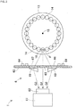
Component transfer device 1 of an embodiment will be described with reference tofigs. 1 to 8 .Fig. 1 is a perspective view showing the overall configuration of a component mounter on which is loaded a component transfer device according to an embodiment. Infig. 1 , twocomponent mounters 9 of the same type are disposed on sharedbase 91.Component mounter 9 is configured by assemblingboard conveyance device 2,component supply device 3,component transfer device 1,component camera 4,control section 5, and the like tomachine base 92. In the figure, the X-axis direction is a direction in which the boards K are loaded and unloaded, the Y-axis direction is a direction perpendicular to the X-axis direction in the horizontal plane, and the Z-axis direction is a vertical direction. -
Board conveyance device 2 is disposed on an upper surface ofmachine base 92 in the vicinity of the center in the longitudinal direction (Y-axis direction) ofcomponent mounter 9. Theboard conveyance device 2 is a so-called double lane type device in which afirst conveyance device 21 and asecond conveyance device 22 are arranged in parallel.First conveyance device 21 has a pair of guide rails that are parallel to the X-axis direction, a pair of conveyor belts (not shown) that are guided by the guide rails and convey the boards K that is loaded thereon, and the like. Further,first conveyance device 21 is provided with a clamping device (not shown) for pushing up and positioning the board K conveyed to the mounting position.Second conveyance device 22 is configured in the same manner asfirst conveyance device 21. -
Component supply device 3 is provided on the front side ofcomponent mounter 9.Component supply device 3 is composed of multipledetachable cassette feeders 31.Cassette feeder 31 includesmain body 32,supply reel 33 provided on the front side ofmain body 32, andcomponent removal section 34 provided on an upper portion of the rear end ofmain body 32. Carrier tape in which a large number of components are sealed at a predetermined pitch is wound and held onsupply reel 33. The carrier tape is fed at a predetermined pitch by a tape feeding mechanism (not shown). As a result, the sealed state of the components is released and components are sequentially fed tocomponent removal section 34. -
Component transfer device 1 is a so-called XY robot-type device that can move in the X-axis direction and the Y-axis direction.Component transfer device 1 is arranged from the rear in the longitudinal direction of component mounter 9 (the upper right side infig. 1 ) to abovecomponent supply device 3 at the front.Component transfer device 1 includeshead drive mechanism 11, mountinghead 12,nozzle holder 13,multiple suction nozzles 14, side imaging section 6 (seefigs. 2 to 5 ), cleaning nozzle 7 (seefigs. 3 to 6 ), positive pressure air supply section 8 (seefig. 6 ), and the like. -
Head drive mechanism 11drives mounting head 12 in the X-axis direction and the Y-axis direction in the horizontal plane.Head drive mechanism 11 can be configured by appropriately adopting various well known techniques. Mountinghead 12 rotatably supportsnozzle holder 13 on its lower side.Multiple suction nozzles 14 are detachably mounted onnozzle holder 13.Suction nozzle 14 picks up a component fromcomponent removal section 34, and mounts the component at a predetermined mounting coordinate position of board K.Component transfer device 1 performs a pickup and mounting cycle by moving tocomponent supply device 3, picking up components using themultiple suction nozzles 14, moving the components to board K viacomponent camera 4, which will be described later, and mounting the components. Further,component transfer device 1 repeats the pickup and mounting cycle to perform mounting operations of components. -
Component transfer device 1 has a nozzle changer, which is not shown infig. 1 .Suction nozzles 14 are exchangeably loaded in each of multiple nozzle loading holes in the nozzle changer. The nozzle changer enables automatic exchanging of themultiple suction nozzles 14 provided onnozzle holder 13. Further, cleaningnozzle 7 is loaded in a nozzle mounting hole of the nozzle changer and can be attached to and removed fromnozzle holder 13. The number and the shape of the nozzle loading holes of the nozzle changer can be appropriately changed. The detailed configuration ofcomponent transfer device 1 is described later. -
Component camera 4 is provided facing upwards on an upper surface ofbase 92 betweenboard conveyance device 2 andcomponent supply device 3.Component camera 4 captures an image of a state in which themultiple suction nozzles 14 are in the process of picking up components fromcomponent removal section 34 and moving the components to board K. As a result,component camera 4 can collectively image components held by themultiple suction nozzles 14. The acquired image data is subjected to image processing, and the pickup state of the component is checked. Further, the pickup state of the component is also checked byside imaging section 6 described later. Upon checking the pickup position of the component, the deviation of the rotation angle, bending of leads, and the like, mounting operation is finely adjusted as necessary. Components that are difficult to mount are discarded. -
Control section 5 is disposed at a front portion ofcover 93 covering an upper portion ofmachine base 92.Control section 5 is configured by using a computer device having a CPU and operating by software.Control section 5 includesinput section 51 anddisplay section 52 as a man-machine interface.Control section 5 controls mounting operation of the components according to mounting job data set in advance. The mounting job data designates the type, quantity, mounting order, and the like of the components mounted on board K bycomponent mounter 9. Further, the mounting job data also specifies the position ofcassette type feeder 31 that holds the component, the mounting coordinate position on board K, the type ofsuction nozzle 14 used for mounting, and the like. - The detailed configuration of
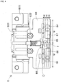
component transfer device 1 according to the embodiment will be described.Fig. 2 is a plan view illustratingnozzle holder 13 andside imaging section 6 ofcomponent transfer device 1 according to an embodiment.Fig. 2 shows a state in whichside imaging section 6images suction nozzle 14 and the component P.Fig. 3 is a plan view showingnozzle holder 13,side imaging section 6, and cleaningnozzle 7 ofcomponent transfer device 1.Fig. 3 shows a state in whichcleaning nozzle 7 is automatically cleaningside imaging section 6. Further,fig. 4 is a view from the arrow A direction offig. 3 , andfig. 5 is a side view from the arrow B direction offig. 3 . - As shown in
fig. 2 ,nozzle holder 13 is detachably equipped with twenty-foursuction nozzles 14 arranged in a circular shape.Nozzle holder 13 is driven by an R-axis drive mechanism (not shown) to rotate aboutcentral axis 15. As a result, themultiple suction nozzles 14 move circumferentially in order to theoperation position 16. Thesuction nozzle 14 atoperation position 16 is driven to move up and down by a Z-axis drive mechanism (not shown), and is lowered to the suction height and mounting height of the component P, and is raised to the moving height when moving horizontally. Further, thesuction nozzle 14 atoperation position 16 is driven by a θ-axis drive mechanism (not shown) to rotate so as to adjust the direction of the held component P. Infig. 2 , a component P held by thesuction nozzle 14 atoperation position 16 is illustrated. -
Side imaging section 6 is disposed opposite tooperation position 16.Side imaging section 6 includescamera section 61 andimaging board section 63.Camera section 61 is fixed to supportmember 611 extending downward from mountinghead 12.Camera section 61 hasimage detection section 62 on the front side, in which a large number of pixels are arranged in a two-dimensional grid pattern. As shown infig. 4 ,imaging board section 63 is a plate-like member that is long laterally when viewed from the front.Imaging board section 63 is fixed to supportplate 631 extending downward from mountinghead 12 by two fastening screws 632.Imaging board section 63 is positioned betweenoperation position 16 andcamera section 61.Imaging board section 63 haslighting section 64 and three light path sections (65, 66, and 67) for imaging. -
Lighting section 64 is provided on a side surface ofimaging board section 63 facingoperation position 16.Lighting section 64 includes 14 LED lamps. The power supply line oflighting section 64 is wired usingsupport plate 631.Lighting section 64 emits light towardsuction nozzle 14 atoperation position 16 and the component P held by thesuction nozzle 14. - Between the fourteen LED lamps of
lighting section 64, centerlight path section 65, rightlight path section 66, and leftlight path section 67 are arranged apart from each other. The light path sections (65, 66, and 67) are substantially rectangular windows formed inimaging board section 63. Transparent glass is fitted into the light path sections (65, 66, and 67). Centerlight path section 65 is located on a straight line connectingoperation position 16 andcamera section 61. Rightlight path section 66 is located on the right side of centrallight path section 65 when viewed fromcamera section 61. Leftlight path section 67 is located on the left side of centerlight path section 65 when viewed fromcamera section 61. Rightlight path section 66 and leftlight path section 67 are positioned slightly lower than centerlight path section 65. -
Right prism 68 is provided on a side of rightlight path section 66 facingcamera section 61.Right prism 68 has a function of refracting an image passing through rightlight path section 66 towardcamera section 61. Similarly, leftprism 69 is provided on a side of leftlight path section 67 facingcamera section 61.Left prism 69 has a function of refracting an image passing through leftlight path section 67 towardcamera section 61. - As indicated by arrow G1 in
fig. 2 , an image obtained by viewingsuction nozzle 14 and the component P atoperation position 16 from the front side passes through centerlight path section 65 and reaches the center ofimage detection section 62. Also, as indicated by arrow G2, an image whensuction nozzle 14 and component P are viewed obliquely rightward passes through right sidelight path section 66, is refracted byright prism 68, and reaches the right side ofimage detection portion 62. Further, as shown by arrow G3, an image whensuction nozzle 14 and component P are viewed obliquely from the left direction passes through leftlight path section 67, is refracted byleft prism 69, and reaches the left side ofimage detection portion 62. As a result,image detection unit 62 can capture an image ofsuction nozzle 14 and component P viewed from three directions at a time when acquiring image data. - When
component transfer device 1 repeats the pickup of component P and mounting on board K, dust gradually adheres tolight path sections imaging board section 63 andlighting section 64.Cleaning nozzle 7 is used to automatically clean dust adhering toimaging board section 63.Cleaning nozzle 7 is loaded on the nozzle changer during the mounting operation of componentsP. Cleaning nozzle 7 is exchanged with one of thesuction nozzles 14 to be mounted onnozzle holder 13. - As shown in
figs. 3 to 5 , cleaningnozzle 7 is a substantially cylindrical member elongated in the vertical direction.Cleaning nozzle 7 is closed at the lower end and the upper end of cleaningnozzle 7 is connected to first nozzle-side air passage 88A described below.Cleaning nozzle 7 hasemission port 71 open only at a side surface and which opens towardside imaging section 6. Positive pressure air is supplied to cleaningnozzle 7 and emitted fromemission port 71. - Next, positive pressure
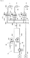
air supply section 8 for supplying positive pressure air to cleaningnozzle 7 will be described.Fig. 6 shows an air supply system for supplying positive pressure air and negative pressure air tosuction nozzle 14. Infig. 6 , an open state of air passages is indicated by a thick solid line, and a blocked state is indicated by a broken line.Fig. 6 illustrates a situation in which positive pressure low pressure air is supplied to cleaningnozzle 7. At least one of high pressureair supply section 82 and low pressureair supply section 83 shown infig. 6 also functions as positive pressureair supply section 8. - More specifically, air supply system includes positive
pressure air source 81, high pressureair supply section 82, low pressureair supply section 83, multiple positivepressure air passages 84, negativepressure air source 85, multiple negativepressure air passages 86, multiplemechanical air valves 87, multiple nozzle-side air passages 88, and the like. The number of positivepressure air passages 84, negativepressure air passages 86,air valves 87, and nozzle-side air passages 88 is twenty-four, which is equal to the number ofsuction nozzles 14 to be attached, with three being shown infig. 6 .Control section 5 also serves as an air control unit for controlling high pressureair supply section 82, low pressureair supply section 83, andair valve 87. - Positive
pressure air source 81 and negativepressure air source 85 are formed, for example, on the discharge side and the suction side of an air pump (not shown). The pressure of the positive pressure air stored in positivepressure air source 81 may be, for example, 0.5MPa, and negative pressure close to a vacuum may be used as the pressure of the negative pressure air stored in negativepressure air source 85.Supply port 811 of positivepressure air source 81 is connected to high pressureair supply section 82 and low pressureair supply section 83. That is, the high-pressureair supply section 82 and the low-pressureair supply section 83 are connected in parallel to the positivepressure air source 81.Supply port 851 of negativepressure air source 85 is branched and is connected with the multiple negativepressure air passages 86. - High pressure
air supply section 82 is configured by highpressure solenoid valve 821. Highpressure solenoid valve 821 opens and closes the air passage under the control ofcontrol section 5. In the open state, highpressure solenoid valve 821 causes high pressure air corresponding to the pressure of positivepressure air source 81 to flow out ofoutlet 822. Highpressure solenoid valve 821 does not allow high pressure air to flow out in the closed state.Fig. 6 illustrates the closed state of highpressure solenoid valve 821. - Low pressure
air supply section 83 is configured by a series connection ofregulator 831 and lowpressure solenoid valve 832.Regulator 831 reduces the air pressure of positivepressure air source 81 and discharges positive low pressure air. Lowpressure solenoid valve 832 opens and closes air passages under the control ofcontrol section 5. In the open state, lowpressure solenoid valve 832 allows low pressure air to flow out ofoutlet 833. Lowpressure solenoid valve 832 does not allow low pressure air to escape in the closed state.Fig. 6 illustrates the open state of lowpressure solenoid valve 832. -
Outlet 822 of highpressure solenoid valve 821 andoutlet 833 of lowpressure solenoid valve 832 are connected tocommon air passage 825.Atmosphere opening valve 826 is provided at a midpoint ofcommon air passage 825.Atmosphere opening valve 826 is a check valve that operates whencommon air passage 825, which maintains a positive pressure during normal operation, is in a negative pressure state.Atmosphere opening valve 826 introduces the atmosphere and eliminates the negative pressure incommon air passage 825.Common air passage 825 is branched to be connected to the multiple positivepressure air passages 84. - Positive
pressure air passage 84 and negativepressure air passage 86 are respectively connected to the inflow sides of themultiple air valves 87. Themultiple air valves 87 are each connected to a nozzle-side air passage 88 on the outflow side.Air valve 87 hasspool 871 for switching the connection state of the air passage under the control ofcontrol section 5. As shown by the Up arrow infig. 6 , whenspool 871 is raised,air valve 87 connects positivepressure air passage 84 and nozzleside air passage 88. As shown by the Dn arrow infig. 6 , whenspool 871 is lowered,air valve 87 connects negativepressure air passage 86 and nozzle-side air passage 88. Further, whenspool 871 is operated to an intermediate height,air valve 87 is shut off. - Each of the multiple nozzle-
side air passages 88 is connected to the interior of an attachedsuction nozzle 14. Infig. 6 , thefirst suction nozzle 14 has been exchanged for cleaningnozzle 7. Therefore, the air supply system has the same system configuration with respect to thecleaning nozzle 7 as that tosuction nozzle 14. That is, cleaningnozzle 7 is connected tofirst air valve 87A by first nozzle-side air passage 88A. Further,first air valve 87 A is connected to positive pressureair supply section 8 by first positivepressure air passage 84A.First air valve 87A is connected to negativepressure air source 85 by first negativepressure air passage 86A. - High pressure
air supply section 82 operates whensuction nozzle 14 is cleaned, and supplies relatively high pressure positive pressure air to the inside ofsuction nozzle 14. As a result, dust accumulated insuction nozzle 14, the component suction port, or the like is blown away. On the other hand, low pressureair supply section 83 operates during normal mounting operation to supply relatively low pressure positive pressure air to the inside ofsuction nozzle 14. As a result,suction nozzle 14 can release a held component P to mount the component on board K or discard it. - Next, operation of
component transfer device 1 according to the embodiment will be described.Fig. 7 shows an operation flow ofcomponent transfer device 1 that mainly operates under the control ofcontrol section 5.Fig. 8 shows a detailed operation flow of the cleaning operation in step S6 offig. 7 . In S1 offig. 7 ,component transfer device 1 performs a pickup and mounting cycle by automatic operation. When one pickup and mounting cycle is completed, in S2,component transfer device 1 stops the cycle. - In the next step, S3,
control section 5 determines whether to perform cleaning ofside imaging section 6. Performing of cleaning is set to at least one of manual or automatic. In the case of the manual setting, an operator inputs a cleaning command viainput section 51 when it is time to perform cleaning. Alternatively, before it is time to perform cleaning, the operator may reserve and set a time to perform cleaning viainput section 51. In the case of the automatic setting,control section 5 determines that cleaning should be performed when the elapsed time from the previous cleaning reaches a predetermined time or when the number of parts mounted since the previous cleaning reaches a predetermined number. If cleaning is not to be performed,control section 5 returns processing to S1, and repeats the pickup and mounting cycle by automatic operation. When the cleaning is performed,control section 5 proceeds to S4. - In S4,
control section 5 returns all thesuction nozzles 14 mounted onnozzle holders 13 to the nozzle changer. As shown infig. 5 , by removingsuction nozzles 14 fromnozzle holders 13, it is possible to prevent dust scattered during cleaning from adhering tosuction nozzles 14. However, the configuration is not limited to this, andcontrol section 5 may return only thefirst suction nozzle 14 to the nozzle changer, as shown infig 6 . In the next step, S5,control section 5 causes thecleaning nozzle 7 to be attached at the position of thenozzle holder 13 where thefirst suction nozzle 14 was attached. In the next step, S6,control section 5 controls the cleaning operation of theside imaging section 6. - In step S11 of
fig. 8 that shows details of the cleaning operation,control section 5moves mounting head 12 andnozzle holder 13 to the cleaning execution position. The cleaning execution position is not particularly limited, but it is preferable to be a position for which any scattered dust has a small impact. In the next step, S12,control section 5 raisesspool 871 offirst air valve 87A. As a result, as illustrated infig. 6 , cleaningnozzle 7 is connected to positive pressureair supply section 8. In the next step, S13,controller 5 lowersspool 871 ofair valves 87 other than thefirst air valve 87A to a lower or an intermediate height. - In the next step, S14,
control section 5 movesemission port 71 of cleaningnozzle 7 to the initial position. In the present embodiment, the initial position is determined such that theemission port 71 is directly opposed to an upper section of centerlight path section 65. In S15,control section 5 sets the number of repetitions R of the cleaning operation to 0. In S16,control section 5 starts the operation of positive pressureair supply section 8. Then, as shown by the five broken line arrows F infigs. 3 and5 , positive pressure air is blown out ofemission port 71 of cleaningnozzle 7 toward centerlight path section 65. As a result, the cleaning ofimaging board section 63 is started. - When only high pressure
air supply section 82 is operated as positive pressureair supply section 8, high pressure air is blown out fromemission port 71. As shown infig. 6 , when only low pressureair supply section 83 is operated as positive pressureair supply section 8, low pressure air is blown out fromemission port 71. Therefore, according to the present embodiment, the strength of the positive pressure air blown out for cleaning can be selected. It is also possible to operate both high pressureair supply section 82 and low pressureair supply section 83. - In the next step, S17, cleaning
nozzle 7 is temporarily stopped at the initial position for a predetermined period of time prior to the rotation operation and the raising and lowering operation which will be described next. As a result, centerlight path section 65, which has a large influence on the quality of the image data, is intensively cleaned. In the next step, S18,control section 5 controls the θ-axis drive mechanism to rotate cleaningnozzle 7. Specifically,control section 5 firstrotates cleaning nozzle 7 by angle Q in the counterclockwise direction infig. 3 , then rotates cleaningnozzle 7 in the clockwise direction by twice the angle Q, and finally rotates cleaningnozzle 7 in the counterclockwise direction by the angle Q. - Angle Q is set so that the cleaning execution range is appropriate in consideration of the width dimension of
imaging board section 63 and the arrangement of the light path sections (65, 66, and 67). It is preferable that the rotation speed of the cleaningnozzle 7 is a level lower than the rotation speed ofsuction nozzle 14 with which mounting operation is normally performed. As a result, a certain amount of time is required for cleaning, butimaging board section 63 is sufficiently cleaned. - In S19, after
emission port 71 has returned to the initial position,control section 5 increases the number of repetitions R by one. In the next step, S20,control section 5 determines whether the number of repetitions R has reached the predetermined number of times Rmax. In the present embodiment, the predetermined number of times Rmax is set to four. Since the number of repetitions is R=1 when S20 has been performed once, controlsection 5 proceeds to S21. - In S21,
control section 5 controls the Z-axis drive mechanism to move cleaningnozzle 7 up and down. More specifically,control section 5 lowers cleaningnozzle 7 by lowering distance H. The size of lowering distance H is set so that the cleaning execution range becomes appropriate with three lowering operations, in consideration of the height dimension ofimaging board section 63 and the arrangement of the light path sections (65, 66, and 67). Next,control section 5 returns processing to S16. When the loop from S16 to S21 has been repeated three times, and steps S16 to S19 have been completed four times, the number of repetitions R=4. Therefore, when S20 is performed for the fourth time,control section 5 proceeds to S22. In S22,control section 5 stops positive pressureair supply section 8. In S23,control section 5 executes post-processing, and returns processing to S7 infig. 7 . For example,control section 5 raisesspool 871 that had been lowered as post-processing. - The blowing direction of
emission port 71, that is, the position ofimaging board section 63 thatemission port 71 is facing, moves as indicated by dashed-line arrow C infig. 4 . The blowing direction ofemission port 71 covers substantially the entire width direction ofimaging board section 63, and the three light path sections (65, 66, and 67) and the majority oflighting section 64 in height direction. Positive pressure air blown out fromemission port 71 blows off the dust adhering toimaging board section 63, and cleaning is performed automatically. In addition, blind spots that are not cleaned do not occur in the light path sections (65, 66, and 67). - In S7 of
fig. 7 ,control section 5 performs control for returningcleaning nozzle 7 to the nozzle changer, then ends the cleaning. In the next step, S8,control section 5 performs control to reattach all thesuction nozzles 14 returned to the nozzle changer to thenozzle holders 13. In the next step, S9,control section 5 resumes automatic operation and returns processing to S1.Control section 5 may determine the resumption of automatic operation by itself, or an operator may be required to confirm the cleaning state and input a resumption command viainput section 51. -
Component transfer device 1 of the embodiment includes: a component mounting tool (suction nozzle 14) mounted on movable mountinghead 12, the component mounting tool being configured to collect a component P fromcomponent supply device 3 and mount the component on board K;side imaging section 6 configured to image the component P held by the component mounting tool from the side; cleaningnozzle 7 havingemission port 71 on a side surface only of the cleaningnozzle 7 that opens towardside imaging section 6; and positive pressureair supply section 8 configured to supply positive pressure air to cleaningnozzle 7 and blow out the positive pressure air fromemission port 71 towardside imaging section 6. - Accordingly, positive pressure
air supply section 8 blows positive pressure air fromemission port 71 of cleaningnozzle 7 towardside imaging section 6. Since the blown positive pressure air blows off the dust adhering toside imaging section 6, the cleaning ofside imaging section 6 is performed automatically. Therefore, maintenance work required to manually cleanside imaging section 6 is reduced. Further, since the quality of image data acquired byside imaging section 6 is maintained at a high level, the occurrence of image processing errors is curtailed. - Furthermore, at least one of cleaning
nozzle 7 and mountinghead 12 performs a rotation operation and a raising and lowering operation in a state where positive pressure air is supplied to cleaningnozzle 7. Accordingly, since the blowing direction of the blowingport 71 moves, a wide range ofside imaging section 6 is cleaned. - Further,
side imaging section 6 includeslighting section 64 configured to illuminate the component P during imaging and a light path section (centerlight path unit 65, rightlight path unit 66, and left light path unit 67) that connects the component P andimage detection unit 62, and at least one of cleaningnozzle 7 and mountinghead 12 temporarily stops or decelerates at least one of a rotation speed and a raising and lowering speed at a position whereemission port 71 faceslight path section 65 at least one of a start timing, an intermediate timing, and an end timing of the rotation operation and the raising and lowering operation. Accordingly, centerlight path section 65, which has a large influence on the quality of the image data, is intensively cleaned. - Further, the component mounting tool is a
suction nozzle 14 that is detachably mounted tonozzle holder 13 of mountinghead 12 and that picks up component P, and cleaningnozzle 7 is exchanged with asuction nozzle 14 and mounted on mountinghead 12. This eliminates the need for a dedicated member such as a mounting seat for mountingcleaning nozzle 7, simplifies the configuration of the device, and curtails an increase in the cost of the device. - Further, at least one of high pressure
air supply section 82 configured to supply positive pressure air with a relatively high pressure to cleansuction nozzle 14 and low pressureair supply section 83 configured to supply positive pressure air with a relatively low pressure to release the component held bysuction nozzle 14 also serves as positive pressureair supply section 8. This eliminates the need to provide the dedicated positive pressureair supply section 8 for cleaning, thereby simplifying the configuration of the apparatus and curtailing an increase in the cost of the device. Also, the strength of the positive pressure air blown out for cleaning can be selected. - The
component transfer device 1 further includes:multiple suction nozzles 14 detachably mounted onnozzle holders 13 of mountinghead 12; multiple positivepressure air passages 84 and multiple nozzle-side air passages 88 individually connecting themultiple suction nozzles 14 and positive pressureair supply section 8;multiple air valves 87 respectively disposed in the multiple positivepressure air passages 84 and performing opening and closing operation independently of each other; and an air control section (control section 5) configured to control positive pressureair supply section 8 and themultiple air valves 87.Cleaning nozzle 7 is mounted on mountinghead 12 by being exchanged with afirst suction nozzle 14, and the air control section is configured to operate positive pressureair supply section 8 after openingfirst air valve 87A disposed in first positivepressure air passage 84A connecting positive pressureair supply section 8 and cleaningnozzle 7, and closing theair valves 87 other than thefirst air valve 87A. Accordingly, a cleaning function ofside imaging section 6 can be provided simply by addingcleaning nozzle 7 to a component transfer device with a conventional configuration. - In an embodiment above,
emission port 71 of cleaningnozzle 7 is temporarily stopped at a position facing centerlight path section 65, but the configuration is not limited thereto. That is,emission port 71 may be temporarily stopped at a position facing rightlight path section 66 or leftlight path section 67. Further,emission port 71 may be not temporarily stopped at a position opposed to the light path section (65, 66, and 67), but may have its rotation speed slowed. Further, in an embodiment above, cleaningnozzle 7 is rotated and lowered, but the configuration is not limited thereto. For example, in a state in which positive pressure air is supplied to cleaningnozzle 7, theentire nozzle holder 13 or mountinghead 12 may perform a raising and lowering operation and rotation operation aroundcenter axis 15. - Further, a support member separate from
nozzle holder 13 may be provided on mountinghead 12 to support cleaningnozzle 7, and positive pressure air may be supplied to cleaningnozzle 7 through a different route from that ofsuction nozzle 14. Further, in a configuration in which a clamping type mounting tool is mounted on the mounting head, it is also possible to exchange the clamping type mounting tool with cleaningnozzle 7. Various other applications and modifications are possible for the configuration and operation of an embodiment. -
- 1:
- component transfer device;
- 12:
- mounting head;
- 13:
- nozzle holder;
- 14:
- suction nozzle;
- 2:
- board conveyance device;
- 3:
- component supply device;
- 4:
- component camera;
- 5:
- control section;
- 6:
- side imaging section;
- 62:
- image detection section;
- 63:
- imaging board section;
- 64:
- lighting section;
- 65:
- center light path section;
- 66:
- right light path section;
- 67:
- left light path section;
- 7:
- cleaning nozzle;
- 71:
- emission port;
- 8:
- positive pressure air supply section;
- 82:
- high pressure air supply section;
- 83:
- low pressure air supply section;
- 84:
- positive pressure air passage;
- 84A:
- first positive pressure air passage;
- 87:
- air valve;
- 87A:
- first air valve;
- 88:
- nozzle-side air passage;
- 88A:
- first nozzle-side air passage;
- 9:
- component mounter
Claims (6)
- A component transfer device comprising:a component mounting tool mounted on a movable mounting head, the component mounting tool being configured to collect a component from a component supply device and mount the component on a board;a side imaging section configured to image the component held by the component mounting tool from the side;a cleaning nozzle having an emission port on a side surface only of the cleaning nozzle that opens toward the side imaging section; anda positive pressure air supply section configured to supply positive pressure air to the cleaning nozzle and blow out the positive pressure air from the emission port toward the side imaging section.
- The component transfer device according to claim 1, wherein
at least one of the cleaning nozzle and the mounting head performs a rotation operation and a raising and lowering operation in a state in which the positive pressure air is being supplied to the cleaning nozzle. - The component transfer device according to claim 2, wherein
the side imaging section includes a lighting section configured to illuminate the component during imaging and a light path section that connects the component and the image detection unit, and at least one of the cleaning nozzle and the mounting head temporarily stops or decelerates at least one of a rotation speed and a raising and lowering speed at a position where the emission port faces the light path section at least one of a start timing, an intermediate timing, and an end timing of the rotation operation and the raising and lowering operation. - The component transfer device according to any one of claims 1 to 3, wherein
the component mounting tool is a suction nozzle detachably mounted on the mounting head for picking up the component, and the cleaning nozzle is exchanged with the suction nozzle and mounted on the mounting head. - The component transfer device according to claim 4, wherein
at least one of a high pressure air supply section configured to supply positive pressure air with a relatively high pressure to clean the suction nozzle and a low pressure air supply section configured to supply positive pressure air with a relatively low pressure to release the component held by the suction nozzle also serves as the positive pressure air supply section. - The component transfer device according to claim 4 or 5, further comprising:multiple of the suction nozzles detachably mounted on the mounting head; multiple air passages individually connecting the multiple suction nozzles and the positive pressure air supply section;multiple air valves respectively disposed in the multiple air passages and performing opening and closing operation independently of each other; andan air control section configured to control the positive pressure air supply section and the multiple air valves,whereinthe cleaning nozzle is mounted on the mounting head by being exchanged with a first suction nozzle, and the air control section is configured to operate the positive pressure air supply section after opening a first air valve disposed in a first air passage connecting the positive pressure air supply section and the cleaning nozzle, and closing the air valves other than the first air valve.
Applications Claiming Priority (1)
| Application Number | Priority Date | Filing Date | Title |
|---|---|---|---|
| PCT/JP2017/007972 WO2018158855A1 (en) | 2017-02-28 | 2017-02-28 | Component transfer device |
Publications (3)
| Publication Number | Publication Date |
|---|---|
| EP3592126A1 true EP3592126A1 (en) | 2020-01-08 |
| EP3592126A4 EP3592126A4 (en) | 2020-03-11 |
| EP3592126B1 EP3592126B1 (en) | 2023-09-13 |
Family
ID=63370309
Family Applications (1)
| Application Number | Title | Priority Date | Filing Date |
|---|---|---|---|
| EP17898831.7A Active EP3592126B1 (en) | 2017-02-28 | 2017-02-28 | Component transfer device |
Country Status (5)
| Country | Link |
|---|---|
| US (1) | US10945359B2 (en) |
| EP (1) | EP3592126B1 (en) |
| JP (1) | JP6792696B2 (en) |
| CN (1) | CN110326376B (en) |
| WO (1) | WO2018158855A1 (en) |
Family Cites Families (6)
| Publication number | Priority date | Publication date | Assignee | Title |
|---|---|---|---|---|
| JP4445087B2 (en) * | 2000-03-22 | 2010-04-07 | Juki株式会社 | Cleaning method for image recognition device |
| JP5014083B2 (en) * | 2007-11-21 | 2012-08-29 | 富士機械製造株式会社 | Side image acquisition device for suction nozzle and parts to be sucked |
| US20120218402A1 (en) * | 2011-02-24 | 2012-08-30 | Universal Instruments Corporation | Component placement process and apparatus |
| JP5665648B2 (en) * | 2011-05-09 | 2015-02-04 | 富士機械製造株式会社 | Adsorbent detection method and component mounting apparatus in suction nozzle of component mounting head |
| JP5978399B2 (en) * | 2013-06-28 | 2016-08-24 | ヤマハ発動機株式会社 | Pressure control device, surface mounter and pressure control method |
| JP2016174036A (en) * | 2015-03-16 | 2016-09-29 | 富士機械製造株式会社 | Cleaning nozzle and cleaning method |
-
2017
- 2017-02-28 CN CN201780087288.2A patent/CN110326376B/en active Active
- 2017-02-28 EP EP17898831.7A patent/EP3592126B1/en active Active
- 2017-02-28 JP JP2019502343A patent/JP6792696B2/en active Active
- 2017-02-28 WO PCT/JP2017/007972 patent/WO2018158855A1/en unknown
- 2017-02-28 US US16/487,618 patent/US10945359B2/en active Active
Also Published As
| Publication number | Publication date |
|---|---|
| JPWO2018158855A1 (en) | 2019-11-07 |
| EP3592126A4 (en) | 2020-03-11 |
| US20190387654A1 (en) | 2019-12-19 |
| CN110326376A (en) | 2019-10-11 |
| JP6792696B2 (en) | 2020-11-25 |
| EP3592126B1 (en) | 2023-09-13 |
| CN110326376B (en) | 2021-04-20 |
| US10945359B2 (en) | 2021-03-09 |
| WO2018158855A1 (en) | 2018-09-07 |
Similar Documents
| Publication | Publication Date | Title |
|---|---|---|
| US9642295B2 (en) | Component mounting device | |
| WO2004066701A1 (en) | Working machine for circuit board and method of feeding component thererto | |
| JP5918633B2 (en) | Electronic component mounting equipment | |
| JPWO2014045661A1 (en) | Electronic circuit component mounting machine | |
| US11259451B2 (en) | Production management device | |
| CN107852849B (en) | Component mounting machine | |
| JP4881123B2 (en) | Mounting machine and method for cleaning parts thereof | |
| US20110007146A1 (en) | Substrate inspection device and substrate inspection method | |
| JP4338848B2 (en) | Electronic component mounting method and apparatus | |
| JP2013179191A (en) | Electronic component supply device and electronic component packaging device | |
| WO2014192168A1 (en) | System for mounting electronic circuit components | |
| EP3592126B1 (en) | Component transfer device | |
| JP2003347794A (en) | Method and apparatus for taking out electronic circuit component | |
| JP2006245028A (en) | Component mounting apparatus, and method of teaching arrangement changing position thereof | |
| EP4093171B1 (en) | Component mounting line | |
| JP2010157623A (en) | Electronic component mounting device and electronic component mounting method | |
| JP7407347B2 (en) | Component mounting equipment | |
| JP6641207B2 (en) | Electronic component mounting machine and production line | |
| JPH10242697A (en) | Electronic part mounting equipment | |
| JP7061703B2 (en) | Production control method | |
| JP7426800B2 (en) | component mounting machine | |
| EP4009759B1 (en) | Mounting device, mounting system, and inspection/mounting method | |
| JP6793050B2 (en) | Surface mounter | |
| WO2021002005A1 (en) | Component mounting machine | |
| JP2021111731A (en) | Component mounting device and nozzle length determination method |
Legal Events
| Date | Code | Title | Description |
|---|---|---|---|
| STAA | Information on the status of an ep patent application or granted ep patent |
Free format text: STATUS: THE INTERNATIONAL PUBLICATION HAS BEEN MADE |
|
| PUAI | Public reference made under article 153(3) epc to a published international application that has entered the european phase |
Free format text: ORIGINAL CODE: 0009012 |
|
| STAA | Information on the status of an ep patent application or granted ep patent |
Free format text: STATUS: REQUEST FOR EXAMINATION WAS MADE |
|
| 17P | Request for examination filed |
Effective date: 20190826 |
|
| AK | Designated contracting states |
Kind code of ref document: A1 Designated state(s): AL AT BE BG CH CY CZ DE DK EE ES FI FR GB GR HR HU IE IS IT LI LT LU LV MC MK MT NL NO PL PT RO RS SE SI SK SM TR |
|
| AX | Request for extension of the european patent |
Extension state: BA ME |
|
| A4 | Supplementary search report drawn up and despatched |
Effective date: 20200212 |
|
| RIC1 | Information provided on ipc code assigned before grant |
Ipc: H05K 13/08 20060101AFI20200206BHEP Ipc: H05K 13/04 20060101ALI20200206BHEP |
|
| DAV | Request for validation of the european patent (deleted) | ||
| DAX | Request for extension of the european patent (deleted) | ||
| STAA | Information on the status of an ep patent application or granted ep patent |
Free format text: STATUS: EXAMINATION IS IN PROGRESS |
|
| STAA | Information on the status of an ep patent application or granted ep patent |
Free format text: STATUS: EXAMINATION IS IN PROGRESS |
|
| 17Q | First examination report despatched |
Effective date: 20210922 |
|
| GRAP | Despatch of communication of intention to grant a patent |
Free format text: ORIGINAL CODE: EPIDOSNIGR1 |
|
| STAA | Information on the status of an ep patent application or granted ep patent |
Free format text: STATUS: GRANT OF PATENT IS INTENDED |
|
| P01 | Opt-out of the competence of the unified patent court (upc) registered |
Effective date: 20230328 |
|
| INTG | Intention to grant announced |
Effective date: 20230609 |
|
| GRAS | Grant fee paid |
Free format text: ORIGINAL CODE: EPIDOSNIGR3 |
|
| GRAA | (expected) grant |
Free format text: ORIGINAL CODE: 0009210 |
|
| STAA | Information on the status of an ep patent application or granted ep patent |
Free format text: STATUS: THE PATENT HAS BEEN GRANTED |
|
| AK | Designated contracting states |
Kind code of ref document: B1 Designated state(s): AL AT BE BG CH CY CZ DE DK EE ES FI FR GB GR HR HU IE IS IT LI LT LU LV MC MK MT NL NO PL PT RO RS SE SI SK SM TR |
|
| REG | Reference to a national code |
Ref country code: GB Ref legal event code: FG4D |
|
| REG | Reference to a national code |
Ref country code: CH Ref legal event code: EP |
|
| REG | Reference to a national code |
Ref country code: DE Ref legal event code: R096 Ref document number: 602017074303 Country of ref document: DE |
|
| REG | Reference to a national code |
Ref country code: IE Ref legal event code: FG4D |
|
| REG | Reference to a national code |
Ref country code: LT Ref legal event code: MG9D |
|
| REG | Reference to a national code |
Ref country code: NL Ref legal event code: MP Effective date: 20230913 |
|
| PG25 | Lapsed in a contracting state [announced via postgrant information from national office to epo] |
Ref country code: GR Free format text: LAPSE BECAUSE OF FAILURE TO SUBMIT A TRANSLATION OF THE DESCRIPTION OR TO PAY THE FEE WITHIN THE PRESCRIBED TIME-LIMIT Effective date: 20231214 |
|
| PG25 | Lapsed in a contracting state [announced via postgrant information from national office to epo] |
Ref country code: SE Free format text: LAPSE BECAUSE OF FAILURE TO SUBMIT A TRANSLATION OF THE DESCRIPTION OR TO PAY THE FEE WITHIN THE PRESCRIBED TIME-LIMIT Effective date: 20230913 Ref country code: RS Free format text: LAPSE BECAUSE OF FAILURE TO SUBMIT A TRANSLATION OF THE DESCRIPTION OR TO PAY THE FEE WITHIN THE PRESCRIBED TIME-LIMIT Effective date: 20230913 Ref country code: NO Free format text: LAPSE BECAUSE OF FAILURE TO SUBMIT A TRANSLATION OF THE DESCRIPTION OR TO PAY THE FEE WITHIN THE PRESCRIBED TIME-LIMIT Effective date: 20231213 Ref country code: LV Free format text: LAPSE BECAUSE OF FAILURE TO SUBMIT A TRANSLATION OF THE DESCRIPTION OR TO PAY THE FEE WITHIN THE PRESCRIBED TIME-LIMIT Effective date: 20230913 Ref country code: LT Free format text: LAPSE BECAUSE OF FAILURE TO SUBMIT A TRANSLATION OF THE DESCRIPTION OR TO PAY THE FEE WITHIN THE PRESCRIBED TIME-LIMIT Effective date: 20230913 Ref country code: HR Free format text: LAPSE BECAUSE OF FAILURE TO SUBMIT A TRANSLATION OF THE DESCRIPTION OR TO PAY THE FEE WITHIN THE PRESCRIBED TIME-LIMIT Effective date: 20230913 Ref country code: GR Free format text: LAPSE BECAUSE OF FAILURE TO SUBMIT A TRANSLATION OF THE DESCRIPTION OR TO PAY THE FEE WITHIN THE PRESCRIBED TIME-LIMIT Effective date: 20231214 Ref country code: FI Free format text: LAPSE BECAUSE OF FAILURE TO SUBMIT A TRANSLATION OF THE DESCRIPTION OR TO PAY THE FEE WITHIN THE PRESCRIBED TIME-LIMIT Effective date: 20230913 |
|
| REG | Reference to a national code |
Ref country code: AT Ref legal event code: MK05 Ref document number: 1612624 Country of ref document: AT Kind code of ref document: T Effective date: 20230913 |
|
| PG25 | Lapsed in a contracting state [announced via postgrant information from national office to epo] |
Ref country code: NL Free format text: LAPSE BECAUSE OF FAILURE TO SUBMIT A TRANSLATION OF THE DESCRIPTION OR TO PAY THE FEE WITHIN THE PRESCRIBED TIME-LIMIT Effective date: 20230913 |
|
| PG25 | Lapsed in a contracting state [announced via postgrant information from national office to epo] |
Ref country code: IS Free format text: LAPSE BECAUSE OF FAILURE TO SUBMIT A TRANSLATION OF THE DESCRIPTION OR TO PAY THE FEE WITHIN THE PRESCRIBED TIME-LIMIT Effective date: 20240113 |
|
| PG25 | Lapsed in a contracting state [announced via postgrant information from national office to epo] |
Ref country code: AT Free format text: LAPSE BECAUSE OF FAILURE TO SUBMIT A TRANSLATION OF THE DESCRIPTION OR TO PAY THE FEE WITHIN THE PRESCRIBED TIME-LIMIT Effective date: 20230913 |