EP3591422B1 - Dispositif radar pour véhicule automobile et méthode de contrôle du dispositif - Google Patents
Dispositif radar pour véhicule automobile et méthode de contrôle du dispositif Download PDFInfo
- Publication number
- EP3591422B1 EP3591422B1 EP19184828.2A EP19184828A EP3591422B1 EP 3591422 B1 EP3591422 B1 EP 3591422B1 EP 19184828 A EP19184828 A EP 19184828A EP 3591422 B1 EP3591422 B1 EP 3591422B1
- Authority
- EP
- European Patent Office
- Prior art keywords
- radar
- field
- view
- obturation
- reflected
- Prior art date
- Legal status (The legal status is an assumption and is not a legal conclusion. Google has not performed a legal analysis and makes no representation as to the accuracy of the status listed.)
- Active
Links
Images


Classifications
-
- G—PHYSICS
- G01—MEASURING; TESTING
- G01S—RADIO DIRECTION-FINDING; RADIO NAVIGATION; DETERMINING DISTANCE OR VELOCITY BY USE OF RADIO WAVES; LOCATING OR PRESENCE-DETECTING BY USE OF THE REFLECTION OR RERADIATION OF RADIO WAVES; ANALOGOUS ARRANGEMENTS USING OTHER WAVES
- G01S13/00—Systems using the reflection or reradiation of radio waves, e.g. radar systems; Analogous systems using reflection or reradiation of waves whose nature or wavelength is irrelevant or unspecified
- G01S13/02—Systems using reflection of radio waves, e.g. primary radar systems; Analogous systems
- G01S13/06—Systems determining position data of a target
-
- G—PHYSICS
- G01—MEASURING; TESTING
- G01S—RADIO DIRECTION-FINDING; RADIO NAVIGATION; DETERMINING DISTANCE OR VELOCITY BY USE OF RADIO WAVES; LOCATING OR PRESENCE-DETECTING BY USE OF THE REFLECTION OR RERADIATION OF RADIO WAVES; ANALOGOUS ARRANGEMENTS USING OTHER WAVES
- G01S13/00—Systems using the reflection or reradiation of radio waves, e.g. radar systems; Analogous systems using reflection or reradiation of waves whose nature or wavelength is irrelevant or unspecified
- G01S13/88—Radar or analogous systems specially adapted for specific applications
- G01S13/93—Radar or analogous systems specially adapted for specific applications for anti-collision purposes
- G01S13/931—Radar or analogous systems specially adapted for specific applications for anti-collision purposes of land vehicles
-
- G—PHYSICS
- G01—MEASURING; TESTING
- G01S—RADIO DIRECTION-FINDING; RADIO NAVIGATION; DETERMINING DISTANCE OR VELOCITY BY USE OF RADIO WAVES; LOCATING OR PRESENCE-DETECTING BY USE OF THE REFLECTION OR RERADIATION OF RADIO WAVES; ANALOGOUS ARRANGEMENTS USING OTHER WAVES
- G01S7/00—Details of systems according to groups G01S13/00, G01S15/00, G01S17/00
- G01S7/02—Details of systems according to groups G01S13/00, G01S15/00, G01S17/00 of systems according to group G01S13/00
- G01S7/28—Details of pulse systems
- G01S7/282—Transmitters
-
- G—PHYSICS
- G01—MEASURING; TESTING
- G01S—RADIO DIRECTION-FINDING; RADIO NAVIGATION; DETERMINING DISTANCE OR VELOCITY BY USE OF RADIO WAVES; LOCATING OR PRESENCE-DETECTING BY USE OF THE REFLECTION OR RERADIATION OF RADIO WAVES; ANALOGOUS ARRANGEMENTS USING OTHER WAVES
- G01S7/00—Details of systems according to groups G01S13/00, G01S15/00, G01S17/00
- G01S7/02—Details of systems according to groups G01S13/00, G01S15/00, G01S17/00 of systems according to group G01S13/00
- G01S7/35—Details of non-pulse systems
-
- G—PHYSICS
- G01—MEASURING; TESTING
- G01S—RADIO DIRECTION-FINDING; RADIO NAVIGATION; DETERMINING DISTANCE OR VELOCITY BY USE OF RADIO WAVES; LOCATING OR PRESENCE-DETECTING BY USE OF THE REFLECTION OR RERADIATION OF RADIO WAVES; ANALOGOUS ARRANGEMENTS USING OTHER WAVES
- G01S7/00—Details of systems according to groups G01S13/00, G01S15/00, G01S17/00
- G01S7/02—Details of systems according to groups G01S13/00, G01S15/00, G01S17/00 of systems according to group G01S13/00
- G01S7/40—Means for monitoring or calibrating
- G01S7/4004—Means for monitoring or calibrating of parts of a radar system
- G01S7/4008—Means for monitoring or calibrating of parts of a radar system of transmitters
- G01S7/4013—Means for monitoring or calibrating of parts of a radar system of transmitters involving adjustment of the transmitted power
-
- B—PERFORMING OPERATIONS; TRANSPORTING
- B60—VEHICLES IN GENERAL
- B60Y—INDEXING SCHEME RELATING TO ASPECTS CROSS-CUTTING VEHICLE TECHNOLOGY
- B60Y2200/00—Type of vehicle
- B60Y2200/10—Road Vehicles
-
- G—PHYSICS
- G01—MEASURING; TESTING
- G01S—RADIO DIRECTION-FINDING; RADIO NAVIGATION; DETERMINING DISTANCE OR VELOCITY BY USE OF RADIO WAVES; LOCATING OR PRESENCE-DETECTING BY USE OF THE REFLECTION OR RERADIATION OF RADIO WAVES; ANALOGOUS ARRANGEMENTS USING OTHER WAVES
- G01S13/00—Systems using the reflection or reradiation of radio waves, e.g. radar systems; Analogous systems using reflection or reradiation of waves whose nature or wavelength is irrelevant or unspecified
- G01S13/88—Radar or analogous systems specially adapted for specific applications
- G01S13/93—Radar or analogous systems specially adapted for specific applications for anti-collision purposes
- G01S13/931—Radar or analogous systems specially adapted for specific applications for anti-collision purposes of land vehicles
- G01S2013/9316—Radar or analogous systems specially adapted for specific applications for anti-collision purposes of land vehicles combined with communication equipment with other vehicles or with base stations
-
- G—PHYSICS
- G01—MEASURING; TESTING
- G01S—RADIO DIRECTION-FINDING; RADIO NAVIGATION; DETERMINING DISTANCE OR VELOCITY BY USE OF RADIO WAVES; LOCATING OR PRESENCE-DETECTING BY USE OF THE REFLECTION OR RERADIATION OF RADIO WAVES; ANALOGOUS ARRANGEMENTS USING OTHER WAVES
- G01S13/00—Systems using the reflection or reradiation of radio waves, e.g. radar systems; Analogous systems using reflection or reradiation of waves whose nature or wavelength is irrelevant or unspecified
- G01S13/88—Radar or analogous systems specially adapted for specific applications
- G01S13/93—Radar or analogous systems specially adapted for specific applications for anti-collision purposes
- G01S13/931—Radar or analogous systems specially adapted for specific applications for anti-collision purposes of land vehicles
- G01S2013/9327—Sensor installation details
- G01S2013/93271—Sensor installation details in the front of the vehicles
-
- G—PHYSICS
- G01—MEASURING; TESTING
- G01S—RADIO DIRECTION-FINDING; RADIO NAVIGATION; DETERMINING DISTANCE OR VELOCITY BY USE OF RADIO WAVES; LOCATING OR PRESENCE-DETECTING BY USE OF THE REFLECTION OR RERADIATION OF RADIO WAVES; ANALOGOUS ARRANGEMENTS USING OTHER WAVES
- G01S13/00—Systems using the reflection or reradiation of radio waves, e.g. radar systems; Analogous systems using reflection or reradiation of waves whose nature or wavelength is irrelevant or unspecified
- G01S13/88—Radar or analogous systems specially adapted for specific applications
- G01S13/93—Radar or analogous systems specially adapted for specific applications for anti-collision purposes
- G01S13/931—Radar or analogous systems specially adapted for specific applications for anti-collision purposes of land vehicles
- G01S2013/9327—Sensor installation details
- G01S2013/93272—Sensor installation details in the back of the vehicles
-
- G—PHYSICS
- G01—MEASURING; TESTING
- G01S—RADIO DIRECTION-FINDING; RADIO NAVIGATION; DETERMINING DISTANCE OR VELOCITY BY USE OF RADIO WAVES; LOCATING OR PRESENCE-DETECTING BY USE OF THE REFLECTION OR RERADIATION OF RADIO WAVES; ANALOGOUS ARRANGEMENTS USING OTHER WAVES
- G01S13/00—Systems using the reflection or reradiation of radio waves, e.g. radar systems; Analogous systems using reflection or reradiation of waves whose nature or wavelength is irrelevant or unspecified
- G01S13/88—Radar or analogous systems specially adapted for specific applications
- G01S13/93—Radar or analogous systems specially adapted for specific applications for anti-collision purposes
- G01S13/931—Radar or analogous systems specially adapted for specific applications for anti-collision purposes of land vehicles
- G01S2013/9327—Sensor installation details
- G01S2013/93274—Sensor installation details on the side of the vehicles
Definitions
- the present invention relates to a radar device for a motor vehicle and its control method. More particularly, the invention relates to the adjustment of the transmission power of the radar signal of the device in the event of obstruction of the field of view of the radar.
- Radar systems assist the driver and can be used to detect obstacles in the front, rear or sides of the vehicle.
- the principle of radar detection sends a fixed frequency wave in a permitted frequency band with a given bandwidth.
- a certain transmission power is applied to have a sufficient detection range to be able to detect obstacles distant from the vehicle.
- the document US 2006/109170 A1 describes a method and a device for adaptive regulation of the power of a radar system, in particular for mobile applications in the automotive field.
- This radar system consists of a radar transmitter and a radar receiver, transmits radar signals and receives radar signals reflected from target objects. The received signals are tested. The transmission power of the radar transmitter is reduced in the event of irregularities, when these irregularities can be attributed to interference from neighboring radar transmitters.
- a radar device for a motor vehicle comprises a radar antenna configured to detect a reflected signal characterized as a reflection of an emitted signal reflected by an object present in the field of view of the radar antenna; a controller configured to transmit at least one radar signal from the radar antenna, the radar signal being transmitted according to a determined object detection transmission power; the controller being configured for detecting the power level of the reflected signal from the transmitted radar signal reflected by the detected object.
- the controller is configured to adjust the transmit power according to the power level of the detected reflected signal to a minimum power sufficient for detection of the detected object.
- the controller can also be configured to transmit a plurality of successive radar signals according to the determined transmit power, the controller being configured to adjust the transmit power according to the average of the power levels of the detected reflected signals.
- the reflected signal can comprise a plurality of reflected waves distributed in the field of view of the radar antenna so that the controller can be configured to detect the power level and the angular orientation, along the main axis of the field of view. vision, of each reflected wave.
- the controller is configured to determine a rate of closure of the field of view of the radar antenna according to the power level and the angular orientation of each detected reflected wave.
- the controller is configured to compare the determined shutter rate with a preset shutter rate threshold.
- the controller can be configured to adjust the transmit power when the shutter rate is above the preset shutter rate threshold.
- the transmission step can comprise the successive transmission of a plurality of radar signals according to the same predefined transmission power and the step of adjusting the transmission power can comprise the adjustment of the power of. emission according to the average of the power levels of the detected reflected signals.
- the reflected signal may include a plurality of reflected waves distributed across the field of view of the radar antenna such that the step of detecting the power level of the reflected signal includes the step of detecting the power level and the level of the reflected signal. angular orientation, along the main axis of the field of view, of each reflected wave.
- the step of adjusting the transmission power can comprise a preliminary step of determining a rate of obstruction of the field of view of the radar antenna according to the power level and the angular orientation of each detected reflected wave. and a step of comparing the determined shutter rate with a predefined shutter rate threshold.
- the step of adjusting the transmission power may include a step of adjusting the transmission power when the shutter rate is greater than the predefined shutter rate threshold.
- a longitudinal axis L and a transverse axis T are defined. “Left”, “right” and “lateral” orientations are defined in the transverse direction. “Front” and “rear” orientations are also defined in the longitudinal direction.
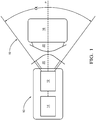
- a radar device 10 comprises a radar antenna 12 and a controller 14.
- the radar device is configured to detect the presence of an object 16 in the field of view 18 of the radar antenna 12.
- the controller 14 is configured to transmit to the radar antenna 12 a radar signal of determined transmission power, so that the radar antenna 12 transmits the radar signal 20 in its field of view 18 along its main transmission axis P. .
- the angular opening ⁇ of the field of view 18 extends symmetrically on either side of the main transmission axis P of the radar device 10.
- the level of the transmission power of the transmitted radar signal 20 and the angular opening ⁇ of the field of view 18 of the radar antenna 12 are determined so as to be able to detect the object 16 present in the field of view 18 up to a maximum distance along the main axis P of emission of the radar device 10.
- the radar antenna 12 is also configured to detect a reflected signal 22 characterized as a reflection of the transmitted signal 20 reflected by the object 16 present in the field of view 18 of the radar antenna 12.
- the controller 14 is also configured to. detecting the power level of the reflected signal 22 detected by the radar antenna 12.
- the controller 14 is configured to adjust the level of the transmission power in particular as a function of the power level of the detected reflected radar signal.
- This characteristic of the radar device 10 of the invention makes it possible in particular to best adjust the energy consumption.
- the controller 14 is configured to adjust the transmission power, according to the power level of the reflected radar signal 22 detected, to a minimum power sufficient for the detection of the object 16 detected. In other words, the controller 14 adjusts the maximum object detection distance by function of the power level of the radar signal 22 reflected by said object 16 detected.
- the transmission power of the radar device 10 is determined beforehand according to a default level so as to be able to detect an object 16 up to a distance of 200 meters from the radar device 10 according to a field of vision of 150 degrees, and if the object 16 detected is located at a distance of the order of a few meters, then the power level of the signal 22 reflected by said object will be analyzed by the controller 14 as being high so that the level of the transmission power of the transmitted radar signal 20 will be readjusted according to a minimum transmission power level necessary to detect the object 16 located a few meters from the radar device 10.
- the transmission power level of the transmitted radar signal 20 is readjusted according to its default value, that is to say a value allowing object detection up to 200 meters according to an angular opening ⁇ d u field of vision of 150 degrees, ie +/- 75 degrees on either side of the main emission axis P.
- the controller 14 can be configured to transmit a plurality of successive radar signals 20 according to the determined transmission power for a determined period of time, the controller 14 being configured to adjust the transmit power according to the average of the power levels of the detected reflected signals 22.
- This method of adjusting the transmission power of the transmitted signal radar 20 also makes it possible to confirm the presence of an object 16 in the field of view 18 of the radar device 10 for a determined period of time.
- the radar device 10 can for example emit radar signals 20 in the field of view 18 of the radar antenna 12 every 50 milliseconds so that the controller 14 can average the power levels of the reflected signals 22 received. by the radar antenna 12 and detected by the controller 14 over a period of 500 milliseconds.
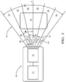
- the controller 14 is configured to distribute the field of view into a plurality of field of view portions 24, 26, 28, 30, 32, 34 extending on either side of the main axis P of emission of the radar device 10.
- the plurality of field of view portions 24, 26, 28, 30, 32, 34 covers fully the field of view 18 of the radar device 10.
- Each portion of the field of view 24, 26, 28, 30, 32, 34 is characterized by its angular opening ⁇ .
- the field of vision portions 24, 26, 28, 30, 32, 34 have a whole identical angular opening ⁇ .
- the controller 14 is configured to locate each portion of the field of view 24, 26, 28, 30, 32, 34 according to its angular distance ⁇ from the main axis P of emission of the radar device 10.
- the reflected signal 22 comprises a plurality of reflected waves 36, 38, 40, 42, 44 distributed in the field of view 18 of the radar antenna 12.
- Each reflected wave 36, 38, 40, 42, 44 is characterized by its angular orientation ⁇ along the main axis P of the field of view 18.
- Each reflected wave 36, 38, 40, 42, 44 received by the radar antenna 12 comes from a portion of the field of view 26, 28, 30, 32, 34.
- the angular orientation ⁇ of each reflected wave 36, 38, 40, 42, 44 allows the controller 14 to associate each reflected wave 36, 38, 40, 42, 44 with the portion of the field of view 26, 28, 30, 32, 34 in which it propagates towards the radar device 10.
- the controller is configured to determine an obstruction rate of the field of view 18 of the radar antenna 12 according to the power level and the angular orientation ⁇ of each detected reflected wave.
- shutter rate refers to the ratio between the portions of the field of view closed 26, 28, 30, 32, 34 and the whole of the field of view 18.
- a method for determining the shutter portions of the field of view by the controller 14 consists in determining the power level of the reflected waves 36, 38, 40, 42, 44 of the portions of the fields of view 26, 28, 30, 32, 34 directly adjacent to each other, and by detecting a power level of the reflected waves 36, 38, 40, 42, 44 of the portions of the fields of view 26, 28, 30, 32, 34 adjacent to one another of the same order of magnitude.
- the order of magnitude of the power level of the reflected waves 36, 38, 40, 42, 44 of the field of vision portions 26, 28, 30, 32, 34 directly adjacent to each other when they are blocked is generally detected and considered to be raised by the controller 14, the object detected generally being at a close distance, that is to say a few meters, from the radar device 10.
- Controller 14 is configured to compare the determined shutter rate with a predefined shutter rate threshold.
- Controller 14 can then be configured to adjust the transmit power when the shutter rate is greater than the preset shutter rate threshold.
- the power of the transmission signal can be reduced if the field of view 18 is blocked to more than 90% by the object 16 detected.
- the transmission power can be adjusted to a minimum power sufficient for the detection of the object 16 present in the field of view 18.
- a control method 100 of the radar device described above and illustrated in figure 1 includes several stages.
- the method comprises a step 110 of transmitting at least one radar signal 20 according to a determined transmission power of object detection from the radar antenna 12 then another step 125 of detecting the power level of the reflected signal 22 originating from the transmitted radar signal 20 reflected by the object 16 detected.
- a step of the control method 100 of the radar device 10 comprises a step 160 of adjusting the transmission power according to the detected power level of the reflected signal 22 at a power minimum sufficient for the detection of the object 16 detected.
- the step 110 of transmitting the radar signal 20 can comprise the successive transmission of a plurality of radar signals 20 according to the same determined transmission power, in particular at regular time intervals, then the step 160 of adjusting the transmission power is carried out as a function of the arithmetic average of the power levels of the reflected signals 22 detected.
- the step 160 of adjusting the transmission power is preceded by a step 150 of comparing the shutter rate of the field of view 18 with a predefined shutter rate threshold.
- the step 160 of adjusting the transmission power comprises a step of reducing the default transmission power of the radar device 10 when the shutter rate of the field of view 18 is greater than the rate threshold. preset shutter.
- the step 125 of detecting the power level of the reflected signal 22 comprises a step 120 of detecting the power level and a step 130 of detecting the angular orientation y, along the main axis P of the field of view 18, of each reflected wave 36, 38, 40, 42, 44.
- the step 140 for determining the rate of obstruction of the radar antenna 12 is therefore carried out according to the power level and the angular orientation ⁇ of each reflected wave 36 , 38, 40, 42, 44 detected.
- the controller 14 is configured to readjust the power of the object. transmit at nominal power by default detection of object 16 of the radar device 10.
- a host vehicle 50 comprises three radar devices similar to the radar device 10 of the figure 1 and some figure 2 .
- a first radar device 52 enables object detection in the front area of host vehicle 10
- a second radar device 54 enables object detection in the right rear area of host vehicle 50
- a third radar device 56 enables detection of object in the left rear area of the host vehicle 50.
- Each radar device 52, 54, 56 is configured to each emit an emission radar signal along its own main emission axis P1, P2, P3 in its own field of view 62, 64, 66.
- the host vehicle 50 travels on the central lane 58 of a road 60 comprising three lanes.
- the host vehicle 50 is in a road traffic situation where a plurality of other vehicles V1, V2, V3, V4, V5, V6, V7, V8 surrounds the host vehicle 50.
- vehicles V1, V2, V3, V4, V5, V6, V7, V8 are located directly in front of the front. of the host vehicle 50, the rear of the host vehicle, the right and left side of the host vehicle 50, the left front and right front of the host vehicle 50, as well as the right rear and the left rear of the host vehicle 50.
- the other vehicles V1, V2, V3, V4, V5, V6, V7, V8 travel in the same direction as the host vehicle 50.
- This road traffic configuration can for example be a situation when queuing at road tolls, red lights or even in traffic jams on wide roads such as highways.
- each radar device 52, 54, 56 transmits a radar signal at a determined nominal object detection power so as to be able to detect at least one vehicle V1, V2, V3, V4, V5, V6, V7, V8 generally targets up to a maximum distance Dm1, Dm2, Dm3 (figure not to scale) much greater than ten meters in its field of vision 62, 64, 66.
- each radar device 52, 54, 56 detects one or more vehicles V1, V2, V3, V4, V5, V6, V7, V8 targets located directly in the vicinity of the host vehicle 50 so that a large portion of each field of view 62, 64, 66 of each radar device 52, 54, 56 is closed.
- each radar device 52, 54, 56 of the host vehicle 50 is in the 'inability to directly detect other vehicles traveling on Route 60.
- the host vehicle 50 is in the same road traffic situation as the figure 4 .
- the maximum object detection distance Dm1, Dm2, Dm3 of each radar device 52, 54, 56 has been reduced by reducing the transmit power to a minimum power level necessary allowing each radar device 52, 54, 56 to detect vehicles V1, V2, V3, V4, V5, V6, V7, V8 targets located in direct proximity to the host vehicle 50.
- the controller 14 of each radar device 52, 54, 56 has determined a rate of blocking of each field of view 62, 64, 66 of each radar device 52, 54.5 greater than a preset shutter rate threshold.
- the method of controlling the radar device 52 arranged in the host vehicle 200 comprises several steps making it possible to adjust the transmission power of the radar device according to the detection of target vehicles. More particularly, the control method 200 comprises a step 210 of transmitting a radar signal 20 from the host vehicle 50 according to a determined object detection power 16. Then the method comprises a step of detecting 220 of the reflected signal 22 issued. of the transmitted radar signal 20 in order to be able to determine the presence of a target vehicle V1 in the field of view 62 of the radar device 52.
- a following step comprises the determination 230 of the rate of closure of the field of view 62 of the radar antenna 12 and a step 240 for comparing the determined shutter rate with a predefined shutter rate threshold.
- the method comprises a step 250 of reducing the transmission power of the radar signal 20 to a minimum power of detection of the target vehicle V1 when the shutter rate is greater than the predefined shutter rate threshold.
- the host vehicle 50 is equipped with a means of communication between vehicles 70 which can communicate directly with other vehicles V1 or indirectly with other vehicles V1 by means of a server 72 broadcasting information received from other vehicles.
- This communication system between vehicles 70 is designated by the English term 'vehicle to everything (V2X)'.
- the host vehicle 50 also comprises an object detection device 74, the object detection device 74 being in communication with the radar devices 52, 54, 55 as described in figures 4 and 5 .
- the object detection device 74 initially comprising the radar device 52 is connected to the means of communication between vehicles 70 so as to be able to detect data relating to the presence of other objects 76 in the portion of his field of vision plugged.
- the host vehicle 50 includes an object detection system 74 comprising the radar device 52 and providing an object detection function in the field of view of the radar device 52 to the vehicle-to-vehicle communication system 70 when the rate d
- the field of view shutter 62 is greater than the preset shutter rate threshold.
- the communication system between vehicles 70 being configured to determine the location coordinates of the closed field of vision, in order to detect the presence of an object 76 in the field of vision blocked by the target vehicle V1, the communication system between vehicles 70 is configured to detect data 78 received by said communication system between vehicles 70 relating to an object 76 present in the field of view 62 closed according to the determined location coordinates.
- the target vehicle V1 located in front of the host vehicle 50 and blocking the field of view 62 of the first radar device 52 of the host vehicle 50 detects the presence of an object 76 via its own radar device.
- the data 80 of the target vehicle V1 relating to the presence of the detected object 76 and the location coordinates of the object 76 are broadcast to the traffic information server 72 by a communication device between the vehicle of the target vehicle V1.
- the inter-vehicle communication system 70 of the host vehicle 50 receives data 78 relating to the presence of the detected object and its location coordinates so that the object detection system 74 of the host vehicle 50 can correlate this information with the location coordinates of the area of the closed field of view.
- the host vehicle 50 can indirectly detect the object located in an area of the field of view of one of its radar devices 52 which is blocked.
- a method of detection 300 of an object 76 by the host vehicle 50 comprising a communication system between vehicles 70 and comprising the method 200 of controlling the radar device 52 arranged in the host vehicle 50, comprises a step of comparing 310 the rate d shuttering the field of view 62 of a radar device 52 with the preset shutter rate threshold.
- the object detection method 300 comprises a step of determining 330 the location coordinates of the closed field of view 62 and finally a step of detecting 340 of the data received 78 by the communication system between vehicles 70 relating to an object 76 present in the device. field of view 62 closed according to the determined location coordinates.
Landscapes
- Engineering & Computer Science (AREA)
- Radar, Positioning & Navigation (AREA)
- Remote Sensing (AREA)
- Physics & Mathematics (AREA)
- Computer Networks & Wireless Communication (AREA)
- General Physics & Mathematics (AREA)
- Electromagnetism (AREA)
- Radar Systems Or Details Thereof (AREA)
Description
- La présente invention concerne un dispositif radar pour véhicule automobile et sa méthode de contrôle. Plus particulièrement, l'invention concerne l'ajustement de la puissance d'émission du signal radar du dispositif en cas d'obturation du champ de vision du radar.
- Les véhicules automobiles sont de plus en plus équipés de système d'aide à la conduite. Une technologie largement utilisée dans ce contexte est le radar. Les systèmes radar aident le conducteur et peuvent être utilisés pour détecter les obstacles à l'avant, à l'arrière ou sur les côtés du véhicule.
- Fondamentalement, le principe de la détection radar envoie une onde à fréquence fixe dans une bande fréquence autorisée avec une bande passante donnée. En outre, une certaine puissance d'émission est appliquée pour avoir une plage de détection suffisante pour pouvoir détecter des obstacles distants du véhicule.
- Lorsque deux ou plusieurs véhicules équipés de systèmes radar se trouvent à proximité des uns des autres, le champ de vision d'un radar d'un véhicule peut être obturé par un autre véhicule. Cela induit une consommation d'énergie électrique associée au radar inutile.
- Le document
US 2006/109170 A1 décrit un procédé et un dispositif de régulation adaptative de la puissance d'un système radar, notamment pour des applications mobiles dans le domaine automobile. Ce système radar comprend un émetteur radar et un récepteur radar, transmet des signaux radar et reçoit des signaux radar réfléchis par des objets cibles. Les signaux reçus sont testés. La puissance de transmission de l'émetteur radar est réduite en cas d'irrégularités, lorsque ces irrégularités peuvent être attribuées à des interférences dues à des émetteurs radar voisins. - Il est donc important de proposer une solution nouvelle résolvant ces problèmes.
- Selon l'invention, un dispositif radar pour véhicule automobile comprend une antenne radar configurée pour détecter un signal réfléchi caractérisé en tant que réflexion d'un signal émis réfléchi par un objet présent dans le champ de vision de l'antenne radar; un contrôleur configuré pour émettre au moins un signal radar depuis l'antenne radar, le signal radar étant émis selon une puissance d'émission déterminée de détection d'objet ; le contrôleur étant configuré pour détecter le niveau de puissance du signal réfléchi issu du signal radar émis réfléchi par l'objet détecté. Le contrôleur est configuré pour ajuster la puissance d'émission selon le niveau de puissance du signal réfléchi détecté à une puissance minimale suffisante pour la détection de l'objet détecté.
- Le contrôleur peut également être configuré pour émettre une pluralité de signaux radar successifs selon la puissance d'émission déterminée, le contrôleur étant configuré pour ajuster la puissance d'émission selon la moyenne des niveaux de puissance des signaux réfléchis détectés.
- Le signal réfléchi peut comprendre une pluralité d'ondes réfléchies réparties dans le champ de vision de l'antenne radar de sorte que le contrôleur peut être configuré pour détecter le niveau de puissance et l'orientation angulaire, selon l'axe principal du champ de vision, de chaque onde réfléchie. Le contrôleur est configuré pour déterminer un taux d'obturation du champ de vision de l'antenne radar selon le niveau de puissance et l'orientation angulaire de chaque onde réfléchie détectée. Le contrôleur est configuré pour comparer le taux d'obturation déterminé avec un seuil de taux d'obturation prédéfini. Le contrôleur peut être configuré pour ajuster la puissance d'émission lorsque le taux d'obturation est supérieur au seuil de taux d'obturation prédéfini.
- Selon l'invention, une méthode de contrôle d'un dispositif radar comprend les étapes de :
- émission d'au moins un signal radar selon une puissance d'émission déterminée de détection d'objet depuis l'antenne radar ;
- détection du niveau de puissance du signal réfléchi issu du signal radar émis réfléchi par l'objet détecté ;
- caractérisé en ce que la méthode comprend l'étape de :
ajustement de la puissance d'émission selon le niveau de puissance détecté du signal réfléchi à une puissance minimale suffisante pour la détection de l'objet détecté. - L'étape d'émission peut comprendre l'émission successive d'une pluralité de signaux radar selon une même puissance d'émission prédéfinie et l'étape d'ajustement de la puissance d'émission peut comprendre l'ajustement de la puissance d'émission selon la moyenne des niveaux de puissance des signaux réfléchis détectés.
- Le signal réfléchi peut comprendre une pluralité d'ondes réfléchies réparties dans le champ de vision de l'antenne radar de sorte que l'étape de détection du niveau de puissance du signal réfléchi comprend l'étape de détection du niveau de puissance et de l'orientation angulaire, selon l'axe principal du champ de vision, de chaque onde réfléchie. L'étape d'ajustement de la puissance d'émission peut comprendre une étape préalable de détermination d'un taux d'obturation du champ de vision de l'antenne radar selon le niveau de puissance et l'orientation angulaire de chaque onde réfléchie détectée et une étape de comparaison du taux d'obturation déterminé avec un seuil de taux d'obturation prédéfini. L'étape d'ajustement de la puissance d'émission peut comprendre une étape d'ajustement de la puissance d'émission lorsque le taux d'obturation est supérieur au seuil de taux d'obturation prédéfini.
- Selon l'invention, une méthode de contrôle d'un dispositif radar agencé dans un véhicule hôte comprend les étapes de :
- émettre un signal radar du véhicule hôte selon une puissance déterminée de détection d'objet;
- détecter un signal réfléchi issu du signal radar émis ;
- déterminer la présence d'un véhicule cible dans le champ de vision du dispositif radar ;
- déterminer un taux d'obturation du champ de vision de l'antenne radar ;
- comparer le taux d'obturation déterminé avec un seuil de taux d'obturation prédéfini ;
- réduire la puissance d'émission du signal radar à une puissance minimale de détection du véhicule cible lorsque le taux d'obturation est supérieur au seuil de taux d'obturation prédéfini.
- Selon l'invention, une méthode de détection d'objet par un véhicule hôte comprenant un système de communication entre véhicules comprend les étapes de :
- comparaison du taux d'obturation du champ de vision d'un dispositif radar avec le seuil de taux d'obturation prédéfini ;
- allouer la fonction de détection d'objet dans le champ de vision du dispositif radar au système de communication entre véhicules lorsque le taux d'obturation est supérieur au seuil de taux d'obturation prédéfini;
- déterminer les coordonnées de localisation du champ de vision obturé;
- détecter des données reçues par le système de communication entre véhicules relatives à un objet présent dans le champ de vision obturé selon les coordonnées de localisation déterminées.
- D'autres caractéristiques, buts et avantages de l'invention apparaîtront à la lecture de la description détaillée qui va suivre, et en regard des dessins annexés, donnés à titre d'exemple non limitatif et sur lesquels:
- La
figure 1 est une vue schématique d'un dispositif radar dans un premier mode de fonctionnement selon l'invention. - La
figure 2 est une vue schématique du dispositif radar de lafigure 1 selon un second mode de fonctionnement. - La
figure 3 est un organigramme d'une méthode de contrôle du dispositif radar de lafigure 1 . - La
figure 4 est une représentation schématique de plusieurs dispositifs radars agencés dans un véhicule hôte et fonctionnant dans un mode usuel lors d'un trafic routier important. - La
figure 5 est une représentation schématique de plusieurs dispositif radar agencés dans un véhicule hôte et fonctionnant selon un mode de fonctionnement de l'invention. - La
figure 6 est un organigramme d'une méthode de contrôle du dispositif radar de lafigure 1 lorsque le dispositif radar est agencé dans un véhicule hôte. - La
figure 7 est une représentation schématique du véhicule hôte circulant dans un trafic routier important et détectant un objet localisé dans une zone de champ de vision obturé d'un dispositif radar du véhicule hôte. - La
figure 8 est un organigramme d'une méthode de détection d'objet par le véhicule hôte lorsque le champ de vision d'un dispositif radar du véhicule hôte est obturé. - Afin de faciliter la description, et de façon non limitative un axe longitudinal L et un axe transversal T sont définis. Des orientations « gauche », « droite » et « latérale » sont définies selon la direction transversale. Des orientations « avant » et « arrière » sont également définies selon la direction longitudinale.
- Selon la
figure 1 , un dispositif radar 10 comprend une antenne radar 12 et un contrôleur 14. Le dispositif radar est configuré pour détecter la présence d'un objet 16 dans le champ de vision 18 de l'antenne radar 12. - Le contrôleur 14 est configuré pour transmettre à l'antenne radar 12 un signal radar de puissance d'émission déterminée, de sorte que l'antenne radar 12 émet le signal radar 20 dans son champ de vision 18 selon son axe principal P d'émission. L'ouverture angulaire α du champ de vision 18 s'étend symétriquement de part et d'autre de l'axe principal P d'émission du dispositif radar 10. Le niveau de la puissance d'émission du signal radar émis 20 et l'ouverture angulaire α du champ de vision 18 de l'antenne radar 12 sont déterminés de sorte à pouvoir détecter l'objet 16 présent dans le champ de vision 18 jusqu'à une distance maximale selon l'axe principal P d'émission du dispositif radar 10.
- L'antenne radar 12 est également configurée pour détecter un signal réfléchi 22 caractérisé en tant que réflexion du signal émis 20 réfléchi par l'objet 16 présent dans le champ de vision 18 de l'antenne radar 12. Le contrôleur 14 est également configuré pour détecter le niveau de puissance du signal réfléchi 22 détecté par l'antenne radar 12.
- Selon l'invention, le contrôleur 14 est configuré pour ajuster le niveau de la puissance d'émission notamment en fonction du niveau de puissance du signal radar réfléchi détecté. Cette caractéristique du dispositif radar 10 de l'invention permet notamment d'ajuster au mieux la consommation en énergie. Plus particulièrement, le contrôleur 14 est configuré pour ajuster la puissance d'émission, selon le niveau de puissance du signal radar réfléchi 22 détecté, à une puissance minimale suffisante pour la détection de l'objet 16 détecté. En d'autres termes, le contrôleur 14 ajuste la distance maximale de détection d'objet en fonction du niveau de puissance du signal radar réfléchi 22 par le dit objet 16 détecté.
- Par exemple et de façon non limitative, si la puissance d'émission du dispositif radar 10 est préalablement déterminée selon un niveau par défaut de sorte à pouvoir détecter un objet 16 jusqu'à une distance de 200 mètres du dispositif radar 10 selon un champ de vision de 150 degrés, et si l'objet 16 détecté se situe à une distance de l'ordre de quelque mètres, alors le niveau de puissance du signal réfléchi 22 par le dit objet sera analysé par le contrôleur 14 comme étant élevé de sorte que le niveau de la puissance d'émission du signal radar émis 20 sera réajusté selon un niveau de puissance d'émission minimal nécessaire pour détecter l'objet 16 localisé à quelque mètres du dispositif radar 10. Cependant, lorsque l'objet 16 sort du champ de vision 18 du dispositif radar 10, alors le niveau de puissance d'émission du signal radar émis 20 est réajusté selon sa valeur par défaut, c'est-à-dire une valeur permettant une détection d'objet jusqu'à 200 mètres selon une ouverture angulaire α du champ de vision de 150 degrés, soit +/- 75 degrés de part et d'autre de l'axe principal P d'émission.
- Afin de ne pas constamment ajuster la puissance d'émission du signal radar émis 20, le contrôleur 14 peut être configuré pour émettre une pluralité de signaux radar 20 successifs selon la puissance d'émission déterminée pendant un laps de temps déterminé, le contrôleur 14 étant configuré pour ajuster la puissance d'émission selon la moyenne des niveaux de puissance des signaux réfléchis 22 détectés. Cette méthode d'ajustement de la puissance d'émission du radar signal émis 20 permet également de confirmer la présence d'un objet 16 dans le champ de vision 18 du dispositif radar 10 pendant une laps de temps déterminé.
- De façon non limitative, le dispositif radar 10 peut par exemple émettre des signaux radars 20 dans le champ de vision 18 de l'antenne radar 12 tous les 50 millisecondes de sorte que le contrôleur 14 puisse moyenner les niveaux de puissance des signaux réfléchis 22 reçus par l'antenne radar 12 et détectés par le contrôler 14 sur une période de 500 millisecondes.
- Selon la
figure 2 , le contrôleur 14 est configuré pour répartir le champ de vision en une pluralité de portion de champ de vision 24, 26, 28, 30, 32, 34 s'étendant de part et d'autre de l'axe principal P d'émission du dispositif radar 10. La pluralité de portion de champ de vision 24, 26, 28, 30, 32, 34 couvre intégralement le champ de vision 18 du dispositif radar 10. Chaque portion de champ de vision 24, 26, 28, 30, 32, 34 est caractérisée par son ouverture angulaire β. De préférence, les portions de champ de vision 24, 26, 28, 30, 32, 34 ont toute une ouverture angulaire β identique. Le contrôleur 14 est configuré pour localiser chaque portion du champ de vision 24, 26, 28, 30, 32, 34 selon sa distance angulaire φ depuis l'axe principal P d'émission du dispositif radar 10. - Selon la
figure 2 , le signal réfléchi 22 comprend une pluralité d'ondes réfléchies 36, 38, 40, 42, 44 répartie dans le champ de vision 18 de l'antenne radar 12. Chaque onde réfléchie 36, 38, 40, 42, 44 est caractérisée par son orientation angulaire γ selon l'axe principal P du champ de vision 18. Chaque onde réfléchie 36, 38, 40, 42, 44 reçue par l'antenne radar 12 provient d'une portion du champ de vison 26, 28, 30, 32, 34. L'orientation angulaire γ de chaque onde réfléchie 36, 38, 40, 42, 44 permet au contrôleur 14 d'associer chaque onde réfléchie 36, 38, 40, 42, 44 à la portion du champ de vision 26, 28, 30, 32, 34 dans lequel elle se propage vers le dispositif radar 10. Lorsque l'objet détecté 16 est proche de l'antenne radar, le champ de vision 18 est partiellement ou complémente obturé par le dit objet 16. Plus précisément, plus l'objet 16 détecté dans le champ de vision 18 est proche du dispositif radar 10, plus une pluralité de portion du champ de vision 28, 30, 32, 34 est obturée par l'objet 16 détecté. Selon l'invention, le contrôleur est configuré pour déterminer un taux d'obturation du champ de vision 18 de l'antenne radar 12 selon le niveau de puissance et l'orientation angulaire γ de chaque onde réfléchie détectée. - On appelle 'taux d'obturation' le ratio entre les portions de champ de vision obturées 26, 28, 30, 32, 34 et l'ensemble du champ de vision 18. De façon non limitative, une méthode de détermination de l'obturation des portions de champs de vision par le contrôleur 14 consiste à déterminer le niveau de puissance des ondes réfléchies 36, 38, 40, 42, 44 des portions de champs de visions 26, 28, 30, 32, 34 directement adjacentes entre elles, et en détectant un niveau de puissance des ondes réfléchies 36, 38, 40, 42, 44 des portions de champs de vision 26, 28, 30, 32, 34 adjacentes entre elles d'un même ordre de grandeur. L'ordre de grandeur du niveau de puissance des ondes réfléchies 36, 38, 40, 42, 44 des portions champs de visions 26, 28, 30, 32, 34 directement adjacentes entre elles lorsqu'elles sont obturées est généralement détecté et considéré comme élevé par le contrôleur 14, l'objet détecté étant généralement à une distance proche, c'est-à-dire quelques mètres, du dispositif radar 10.
- Le contrôleur 14 est configuré pour comparer le taux d'obturation déterminé avec un seuil de taux d'obturation prédéfini.
- Le contrôleur 14 peut alors être configuré pour ajuster la puissance d'émission lorsque le taux d'obturation est supérieur au seuil de taux d'obturation prédéfini.
- Par exemple et de manière non limitative, la puissance du signal d'émission peut être réduite si le champ de vision 18 est obturé à plus de 90% par l'objet 16 détecté. La puissance d'émission peut être ajustée à une puissance minimale suffisante pour la détection de l'objet 16 présent dans le champ de vision 18.
- Selon la
figure 3 , une méthode de contrôle 100 du dispositif radar décrit ci-à la ci-dessus et illustré à lafigure 1 comprend plusieurs étapes. - Afin de détecter un objet 16 dans le champ de vision 18 de l'antenne radar 12, la méthode comprend une étape d'émission 110 d'au moins un signal radar 20 selon une puissance d'émission déterminée de détection d'objet depuis l'antenne radar 12 puis une autre étape de détection 125 du niveau de puissance du signal réfléchi 22 issu du signal radar émis 20 réfléchi par l'objet 16 détecté. Afin de limiter la consommation en énergie du dispositif radar 10, une étape de la méthode de contrôle 100 du dispositif radar 10 comprend une étape d'ajustement 160 de la puissance d'émission selon le niveau de puissance détecté du signal réfléchi 22 à une puissance minimale suffisante pour la détection de l'objet 16 détecté.
- Pour confirmer la présence de l'objet dans le champ de vision 18, l'étape d'émission 110 du signal radar 20 peut comprendre l'émission successive d'une pluralité de signaux radar 20 selon la même puissance d'émission déterminée, notamment à intervalle de temps régulier puis l'étape d'ajustement 160 de la puissance d'émission s'effectue en fonction de la moyenne arithmétique des niveaux de puissance des signaux réfléchis 22 détectés.
- Afin de diminuer la puissance d'émission du signal radar émis 20 lorsque le champ de vision 18 du dispositif radar 10 au-delà de l'objet 16 détecté n'est pas nécessaire, soit parce que le champ de vision 18 est obturé ou soit par ce que le champ de vision non obturé est trop étroit, l'étape d'ajustement 160 de la puissance d'émission est précédée par une étape de comparaison 150 du taux d'obturation du champ de vision 18 avec un seuil de taux d'obturation prédéfini. Enfin l'étape d'ajustement 160 de la puissance d'émission comprend une étape de diminution de la puissance d'émission par défaut du dispositif radar 10 lorsque le taux d'obturation du champ de vision 18 est supérieur au seuil de taux d'obturation prédéfini.
- Afin de déterminer le taux d'obturation du champ de vision 18, et puisque le signal réfléchi 22 comprend une pluralité d'ondes réfléchies 36, 38, 40, 42, 44 réparties dans le champ de vision 18 de l'antenne radar 12, l'étape de détection 125 du niveau de puissance du signal réfléchi 22 comprend une étape de détection 120 du niveau de puissance et une étape de détection 130 de l'orientation angulaire y, selon l'axe principal P du champ de vision 18, de chaque onde réfléchie 36, 38, 40, 42, 44. Enfin l'étape de détermination 140 du taux d'obturation de l'antenne radar 12 est donc réalisée selon le niveau de puissance et l'orientation angulaire γ de chaque onde réfléchie 36, 38, 40, 42, 44 détectée.
- Il est à noter que lorsque le dispositif radar 10 est configuré selon la puissance ajustée à la puissance minimale de détection de l'objet 16, lorsque l'objet 16 n'est plus détecté, le contrôleur 14 est configuré pour réajuster la puissance d'émission à la puissance nominale par défaut de détection d'objet 16 du dispositif radar 10.
- Selon la
figure 4 , un véhicule hôte 50 comprend trois dispositifs radar similaire au dispositif radar 10 de lafigure 1 et de lafigure 2 . Un premier dispositif radar 52 permet la détection d'objet dans la zone avant du véhicule hôte 10, un second dispositif radar 54 permet la détection d'objet dans la zone arrière droite du véhicule hôte 50 et un troisième dispositif radar 56 permet la détection d'objet dans la zone arrière gauche du véhicule hôte 50. Chaque dispositif radar 52, 54, 56 est configuré pour émettre chacun un signal radar d'émission selon son propre axe principal P1, P2, P3 d'émission dans son propre champ de vision 62, 64, 66. - De façon non limitative à l'invention, le véhicule hôte 50 circule sur la voie centrale 58 d'une route 60 comprenant trois voies. Le véhicule hôte 50 est dans une situation de trafic routier selon lequel une pluralité d'autres véhicules V1, V2, V3, V4, V5, V6, V7, V8 entoure le véhicule hôte 50. Plus particulièrement, des véhicules V1, V2, V3, V4, V5, V6, V7, V8 se trouvent directement à proximité de l'avant du véhicule hôte 50, de l'arrière du véhicule hôte, du côté droit et du côté gauche du véhicule hôte 50, à l'avant gauche et à l'avant droit du véhicule hôte 50, ainsi qu'à l'arrière droit et l'arrière gauche du véhicule hôte 50.
- Selon cette situation particulière de trafic routier, les autres véhicules V1, V2, V3, V4, V5, V6, V7, V8 circulent selon la même direction que le véhicule hôte 50. Cette configuration de trafic routier peut par exemple être une situation lors de file d'attente à des péages routiers, à des feux rouges ou encore lors d'embouteillage sur des larges voies telles que des autoroutes.
- Selon un fonctionnement usuel, chaque dispositif radar 52, 54, 56 émet un signal radar à une puissance déterminée nominale de détection d'objet de sorte à pouvoir détecter au moins un véhicule V1, V2, V3, V4, V5, V6, V7, V8 cible généralement jusqu'à une distance maximal Dm1, Dm2, Dm3 (figure non à l'échelle) bien supérieure à une dizaine de mètres dans son champ de vision 62, 64, 66. Selon la
figure 4 , chaque dispositif radar 52, 54, 56 détecte un ou plusieurs véhicules V1, V2, V3, V4, V5, V6, V7, V8 cibles localisés directement à proximité du véhicule hôte 50 de sorte qu'une large portion de chaque champ de vision 62, 64, 66 de chaque dispositif radar 52, 54, 56 est obturée. En d'autre terme, par la présence des véhicules cibles V1, V2, V3, V4, V5, V6, V7, V8 à proximité direct du véhicule hôte 50, chaque dispositif radar 52, 54, 56 du véhicule hôte 50 est dans l'incapacité de détecter directement d'autres véhicules circulant sur la route 60. - Selon la
figure 5 , le véhicule hôte 50 est dans la situation de trafic routier identique à lafigure 4 . Selon la méthode de contrôle 100 du dispositif radar 10 décrite à lafigure 3 , la distance maximale Dm1, Dm2, Dm3 de détection d'objet de chaque dispositif radar 52, 54, 56 a été réduite en réduisant la puissance d'émission selon un niveau de puissance minimale nécessaire permettant à chaque dispositif radar 52, 54, 56 de détecter les véhicules V1, V2, V3, V4, V5, V6, V7, V8 cibles localisés à proximité direct du véhicule hôte 50. Plus précisément, le contrôleur 14 de chaque dispositif radar 52, 54, 56 a déterminé un taux d'obturation de chaque champ de vision 62, 64, 66 de chaque dispositif radar 52, 54, 5 supérieur à un seuil de taux d'obturation prédéfini. - Selon la
figure 6 , lorsqu'un dispositif radar 52, similaire au dispositif radar 10 décrit et illustré à lafigure 1 et à lafigure 2 , est agencé dans le véhicule hôte 50 comme illustré auxfigures 4 et5 , la méthode de contrôle du dispositif radar 52 agencé dans le véhicule hôte 200 comprend plusieurs étapes permettant d'ajuster la puissance d'émission du dispositif radar selon la détection de véhicules cibles. Plus particulièrement, la méthode de contrôle 200 comprend une étape 210 d'émission d'un signal radar 20 du véhicule hôte 50 selon une puissance déterminée de détection d'objet 16. Puis la méthode comprend une étape de détection 220 du signal réfléchi 22 issu du signal radar émis 20 afin de pouvoir déterminer la présence d'un véhicule cible V1 dans le champ de vision 62 du dispositif radar 52. Une étape suivante comprend la détermination 230 du taux d'obturation du champ de vision 62 de l'antenne radar 12 et une étape de comparaison 240 du taux d'obturation déterminé avec un seuil de taux d'obturation prédéfini. Enfin la méthode comprend une étape de réduction 250 de la puissance d'émission du signal radar 20 à une puissance minimale de détection du véhicule V1 cible lorsque le taux d'obturation est supérieur au seuil de taux d'obturation prédéfini. - Selon la
figure 7 , le véhicule hôte 50 est équipé d'un moyen de communication entre véhicules 70 pouvant communiquer directement avec d'autres véhicules V1 ou indirectement avec d'autres véhicules V1 par le biais d'un serveur 72 diffusant des informations reçus d'autres véhicules. Ce système de communication entre véhicules 70 est désigné par le terme anglophone 'vehicle to everything (V2X)'. Le véhicule hôte 50 comprend également un dispositif de détection d'objet 74, le dispositif de détection d'objet 74 étant en communication avec les dispositifs radars 52, 54, 55 tels que décrits auxfigures 4 et5 . - Selon l'invention, afin de pouvoir détecter un autre objet 76 localisé dans la zone d'un champ de vision 62 obturé d'un dispositif radar 52 par un véhicule cible V1, et lorsque le dispositif radar 52 a ajusté le niveau de puissance du signal radar émis 20 selon un niveau de puissance réduit, le dispositif de détection d'objet 74 comprenant initialement le dispositif radar 52 se connecte au moyen de communication entre véhicules 70 de sorte à pouvoir détecter des données relatives à la présence d'autres objets 76 dans la portion de son champ de vision obturé.
- Plus particulièrement, le véhicule hôte 50 comprend un système de détection d'objet 74 comprenant le dispositif radar 52 et allouant une fonction de détection d'objet dans le champ de vision du dispositif radar 52 au système de communication entre véhicules 70 lorsque le taux d'obturation du champ de vision 62 est supérieur au seuil de taux d'obturation prédéfini. Le système de communication entre véhicules 70 étant configuré pour déterminer les coordonnées de localisation du champ de vision obturé, afin de détecter la présence d'objet 76 dans le champ de vision obturé par le véhicule V1 cible, le système de communication entre véhicules 70 est configuré pour détecter des données 78 reçues par le dit système de communication entre véhicules 70 relatives à un objet 76 présent dans le champ de vision 62 obturé selon les coordonnées de localisation déterminées.
- A titre d'exemple et de façon non limitative, selon la
figure 7 , le véhicule V1 cible localisé à l'avant du véhicule hôte 50 et obturant le champ de vision 62 du premier dispositif radar 52 du véhicule hôte 50 détecte la présence d'un objet 76 via son propre dispositif radar. Les données 80 du véhicule V1 cible relatives à la présence de l'objet 76 détecté et des coordonnées de localisation de l'objet 76 sont diffusées au serveur 72 d'information routière par un dispositif de communication entre véhicule du véhicule V1 cible. Le système de communication entre véhicules 70 du véhicule hôte 50 reçoit les données 78 relatives à la présence de l'objet détecté et à ses coordonnées de localisation de sorte que le système de détection d'objet 74 du véhicule hôte 50 puisse corréler ces informations avec les coordonnées de localisation de la zone du champ de vision obturé. Ainsi le véhicule hôte 50 peut détecter indirectement l'objet localisé dans une zone du champ de vision d'un de ses dispositifs radar 52 obturé. - Selon la
figure 8 , une méthode de détection 300 d'objet 76 par le véhicule hôte 50 comprenant un système de communication entre véhicules 70 et comportant la méthode de contrôle 200 du dispositif radar 52 agencé dans le véhicule hôte 50, comprend une étape de comparaison 310 du taux d'obturation du champ de vision 62 d'un dispositif radar 52 avec le seuil de taux d'obturation prédéfini. Une étape d'allocation 320 d'une fonction de détection d'objet dans le champ de vision 62 du dispositif radar 52 au système de communication entre véhicules 70 lorsque le taux d'obturation est supérieur au seuil de taux d'obturation prédéfini. La méthode détection d'objet 300 comprend une étape de détermination 330 des coordonnées de localisation du champ de vision obturé 62 et enfin une étape de détection 340 des données reçues 78 par le système de communication entre véhicules 70 relatives à un objet 76 présent dans le champ de vision 62 obturé selon les coordonnées de localisation déterminées.
Claims (8)
- Dispositif radar (10) pour véhicule (50) automobile comprenant :une antenne radar (12) configurée pour détecter un signal réfléchi (22) caractérisé en tant que réflexion d'un signal émis (20) réfléchi par un objet (16) présent dans le champ de vision (18) de l'antenne radar (12);un contrôleur (14) configuré pour émettre au moins un signal radar (20) depuis l'antenne radar (12), le signal radar (20) étant émis selon une puissance d'émission déterminée de détection d'objet (16); le contrôleur (14) étant configuré pour détecter le niveau de puissance du signal réfléchi (22) issu du signal radar (20) émis réfléchi par l'objet (16) détecté ;caractérisé en ce que le contrôleur (14) est configuré pour ajuster la puissance d'émission selon le niveau de puissance du signal réfléchi (22) détecté à une puissance minimale suffisante pour la détection de l'objet (16) détecté.
- Dispositif radar (10) selon la revendication précédente caractérisé en ce que le contrôleur (14) est configuré pour émettre une pluralité de signaux radar (20) successifs selon la puissance d'émission déterminée, le contrôleur (14) étant configuré pour ajuster la puissance d'émission selon la moyenne des niveaux de puissance des signaux réfléchis (22) détectés.
- Dispositif radar (10) selon l'une quelconque des revendications précédentes caractérisé en ce que lele signal réfléchi (22) comprend une pluralité d'ondes réfléchies (36, 38, 40, 42, 44) réparties dans le champ de vision (18) de l'antenne radar (18);le contrôleur (14) est configuré pour détecter le niveau de puissance et l'orientation angulaire (y), selon l'axe principal (P) du champ de vision (18), de chaque onde réfléchie (36, 38, 40, 42, 44);le contrôleur (14) est configuré pour déterminer un taux d'obturation du champ de vision (18) de l'antenne radar (12) selon le niveau de puissance et l'orientation angulaire (y) de chaque onde réfléchie (36, 38, 40, 42, 44) détectée ;le contrôleur (14) est configuré pour comparer le taux d'obturation déterminé avec un seuil de taux d'obturation prédéfini ;le contrôleur (14) est configuré pour ajuster la puissance d'émission lorsque le taux d'obturation est supérieur au seuil de taux d'obturation prédéfini.
- Méthode de contrôle (100) d'un dispositif radar (10) de l'une quelconque des revendications précédentes la méthode comprenant les étapes de :émission (110) d'au moins un signal radar (20) selon une puissance d'émission déterminée de détection d'objet (16) depuis l'antenne radar (12);détection (125) du niveau de puissance du signal réfléchi (22) issu du signal radar émis (20) réfléchi par l'objet (16) détecté ;caractérisé en ce que la méthode (100) comprend l'étape de :
ajustement (160) de la puissance d'émission selon le niveau de puissance détecté du signal réfléchi (22) à une puissance minimale suffisante pour la détection de l'objet (16) détecté. - Méthode de contrôle (100) selon la revendication précédente caractérisé en ce quel'étape d'émission (110) comprend l'émission successive d'une pluralité de signaux radar (20) selon une même puissance d'émission prédéfinie ;l'étape d'ajustement (160) de la puissance d'émission comprend l'ajustement de la puissance d'émission selon la moyenne des niveaux de puissance des signaux réfléchis (22) détectés.
- Méthode de contrôle (100) selon l'une quelconque des revendications 4 ou 5 pour laquelle le signal réfléchi (22) comprend une pluralité d'ondes réfléchies (36, 38, 40, 42, 44) réparties dans le champ de vision (18) de l'antenne radar (12) ; caractérisé en ce quel'étape de détection (125) du niveau de puissance du signal réfléchi (22) comprend une étape de détection (120) du niveau de puissance de chaque onde réfléchie (36, 38, 40, 42, 44) et une étape de détection (130) de l'orientation angulaire (y), selon l'axe principal (P) du champ de vision (18), de chaque onde réfléchie (36, 38, 40, 42, 44);l'étape d'ajustement (160) de la puissance d'émission comprend :une étape préalable de détermination (140) d'un taux d'obturation du champ de vision (18) de l'antenne radar (12) selon le niveau de puissance et l'orientation angulaire (y) de chaque onde réfléchie (36, 38, 40, 42, 44) détectée ;une étape préalable de comparaison (150) entre le taux d'obturation déterminé et un seuil de taux d'obturation prédéfini ;l'étape d'ajustement (160) de la puissance d'émission lorsque le taux d'obturation est supérieur au seuil de taux d'obturation prédéfini.
- Méthode de contrôle (200) d'un dispositif radar (52) agencé dans un véhicule hôte (50) comprenant la méthode (100) de la revendication 6, la méthode de contrôle (200) du dispositif radar (52) agencé dans le véhicule hôte (50) comprenant les étapes de :émettre (210) un signal radar (20) du véhicule hôte (50) selon une puissance déterminée de détection d'objet (16);détecter (220) un signal réfléchi (22) issu du signal radar émis (20);déterminer la présence (230) d'un véhicule cible (V1) dans le champ de vision (62) du dispositif radar (52);déterminer (230) un taux d'obturation du champ de vision (62) de l'antenne radar (12);comparer (240) le taux d'obturation déterminé avec un seuil de taux d'obturation prédéfini ;réduire (250) la puissance d'émission du signal radar (20) à une puissance minimale de détection du véhicule cible (V1) lorsque le taux d'obturation est supérieur au seuil de taux d'obturation prédéfini.
- Méthode de détection (300) d'objet (76) par un véhicule hôte (50) comprenant la méthode de contrôle (200) du dispositif radar (52) de la revendication 7, le véhicule hôte (50) comprenant un système de communication entre véhicules (70), caractérisé en ce que la méthode (300) comprend les étapes de :comparaison (310) du taux d'obturation du champ de vision (62) du dispositif radar (52) avec le seuil de taux d'obturation prédéfini.allouer (320) la fonction de détection d'objet (76) dans le champ de vision (62) du dispositif radar (52) au système de communication entre véhicules (70) lorsque le taux d'obturation est supérieur au seuil de taux d'obturation prédéfini;déterminer (330) les coordonnées de localisation du champ de vision (62) obturé;détecter (340) des données reçues (78) par le système de communication entre véhicules (70) relatives à un objet (76) présent dans le champ de vision (62) obturé selon les coordonnées de localisation déterminées.
Applications Claiming Priority (1)
| Application Number | Priority Date | Filing Date | Title |
|---|---|---|---|
| FR1856202A FR3083620B1 (fr) | 2018-07-05 | 2018-07-05 | Dispositif radar pour vehicule automobile et methode de controle du dispositif |
Publications (2)
| Publication Number | Publication Date |
|---|---|
| EP3591422A1 EP3591422A1 (fr) | 2020-01-08 |
| EP3591422B1 true EP3591422B1 (fr) | 2021-09-29 |
Family
ID=65031374
Family Applications (1)
| Application Number | Title | Priority Date | Filing Date |
|---|---|---|---|
| EP19184828.2A Active EP3591422B1 (fr) | 2018-07-05 | 2019-07-05 | Dispositif radar pour véhicule automobile et méthode de contrôle du dispositif |
Country Status (4)
| Country | Link |
|---|---|
| US (1) | US11287513B2 (fr) |
| EP (1) | EP3591422B1 (fr) |
| CN (1) | CN110749884B (fr) |
| FR (1) | FR3083620B1 (fr) |
Families Citing this family (8)
| Publication number | Priority date | Publication date | Assignee | Title |
|---|---|---|---|---|
| US11183071B2 (en) * | 2018-08-31 | 2021-11-23 | International Business Machines Corporation | Drone flight optimization using drone-to-drone permissioning |
| DE102020103101B4 (de) * | 2020-02-06 | 2022-07-28 | Audi Aktiengesellschaft | Verfahren zum Betrieb eines Radarsensors in einem Kraftfahrzeug und Kraftfahrzeug |
| CN115298566A (zh) * | 2020-03-30 | 2022-11-04 | 三菱电机株式会社 | 物体检测系统和物体检测方法 |
| FR3109452B1 (fr) * | 2020-04-16 | 2022-03-11 | Renault Sas | Procédé de détection d’une situation d’embouteillage sur un véhicule automobile. |
| EP3951420B1 (fr) * | 2020-08-07 | 2024-11-06 | Aptiv Technologies AG | Système de détection d'objet à l'aide d'un canal de communication latéral |
| US12085636B2 (en) * | 2020-10-15 | 2024-09-10 | Raytheon Company | Systems and methods for detection and tracking of unmanned aerial systems |
| CN113655470B (zh) * | 2021-08-09 | 2023-10-10 | 珠海格力电器股份有限公司 | 对象检测方法、装置、设备及存储介质 |
| US20250116754A1 (en) * | 2023-10-10 | 2025-04-10 | Nxp B.V. | Transmit power control for automotive radar sensing |
Family Cites Families (16)
| Publication number | Priority date | Publication date | Assignee | Title |
|---|---|---|---|---|
| US5160933A (en) * | 1990-08-28 | 1992-11-03 | Honeywell Inc. | Radar altimeter with self-calibration feature |
| US5345470A (en) * | 1993-03-31 | 1994-09-06 | Alexander Richard O | Methods of minimizing the interference between many multiple FMCW radars |
| FR2718249B1 (fr) * | 1994-04-05 | 1996-04-26 | Thomson Csf | Procédé et dispositif radar de mesure de distance. |
| US5485159A (en) | 1994-08-24 | 1996-01-16 | Delco Electronics Corporation | Apparatus and method to detect radar radome obstruction |
| US5670962A (en) * | 1995-11-13 | 1997-09-23 | Delco Electronics Corp. | Transmit power control for automotive radar system |
| DE19921844A1 (de) * | 1999-05-11 | 2000-11-23 | Bosch Gmbh Robert | Vorrichtung zur Detektion von Objekten in der Umgebung eines Fahrzeugs |
| US6469659B1 (en) | 2001-05-03 | 2002-10-22 | Delphi Technologies, Inc. | Apparatus and method for detecting radar obstruction |
| DE10254982A1 (de) * | 2002-11-26 | 2004-06-03 | Robert Bosch Gmbh | Verfahren und Einrichtung zur adaptiven Leistungsregelung |
| JP4189858B2 (ja) * | 2004-11-16 | 2008-12-03 | 株式会社ホンダアクセス | 障害物検知装置 |
| DE102006061670A1 (de) * | 2006-12-28 | 2008-07-03 | Robert Bosch Gmbh | Verfahren zum Betreiben eines Radars und ein Radar |
| JP2010261784A (ja) * | 2009-05-01 | 2010-11-18 | Denso Corp | レーダ装置 |
| TWI435635B (zh) * | 2010-11-19 | 2014-04-21 | Ind Tech Res Inst | 動態無線傳輸功率控制方法與系統 |
| US8441394B2 (en) | 2011-07-11 | 2013-05-14 | Delphi Technologies, Inc. | System and method for detecting obstructions and misalignment of ground vehicle radar systems |
| EP2741106A1 (fr) * | 2012-12-10 | 2014-06-11 | AIRBUS HELICOPTERS DEUTSCHLAND GmbH | Système de radar centrifuge de détection d'obstacle et d'alerte de terrain |
| US9329072B2 (en) * | 2013-12-06 | 2016-05-03 | Honeywell International Inc. | Receiver with programmable gain for UWB radar |
| US9329073B2 (en) * | 2013-12-06 | 2016-05-03 | Honeywell International Inc. | Adaptive radar system with mutliple waveforms |
-
2018
- 2018-07-05 FR FR1856202A patent/FR3083620B1/fr active Active
-
2019
- 2019-06-28 US US16/456,806 patent/US11287513B2/en active Active
- 2019-07-03 CN CN201910593894.2A patent/CN110749884B/zh active Active
- 2019-07-05 EP EP19184828.2A patent/EP3591422B1/fr active Active
Also Published As
| Publication number | Publication date |
|---|---|
| CN110749884B (zh) | 2023-12-19 |
| US20200011966A1 (en) | 2020-01-09 |
| FR3083620B1 (fr) | 2020-06-12 |
| CN110749884A (zh) | 2020-02-04 |
| US11287513B2 (en) | 2022-03-29 |
| EP3591422A1 (fr) | 2020-01-08 |
| FR3083620A1 (fr) | 2020-01-10 |
Similar Documents
| Publication | Publication Date | Title |
|---|---|---|
| EP3591422B1 (fr) | Dispositif radar pour véhicule automobile et méthode de contrôle du dispositif | |
| CN107844796B (zh) | 冰和雪的检测系统和方法 | |
| US9733348B2 (en) | Vehicle radar with beam adjustment | |
| CN104969090B (zh) | 检测车辆周围的物体目标的装置以及方法 | |
| US8577552B1 (en) | Forward collision warning system with road-side target filtering | |
| EP3948820B1 (fr) | Procédé de sécurisation de franchissement d'un feu de circulation par un véhicule, ainsi que produit programme d'ordinateur correspondant | |
| EP3749561A1 (fr) | Système et procédé de détection d'un risque de collision entre un véhicule automobile et un objet secondaire situé sur les voies de circulation adjacentes audit véhicule lors d'un changement de voie | |
| CN114179820A (zh) | 车辆自动驾驶控制方法和装置 | |
| US10408937B2 (en) | Metal bridge detection systems and methods | |
| US11801831B2 (en) | Parking control apparatus and parking control method | |
| US20240192360A1 (en) | Driving assistance system and driving assistance method | |
| FR3092722A1 (fr) | Retransmission selective de messages dans des communications vehicule à vehicule | |
| EP4136475B1 (fr) | Procédé de détection d'une situation d'embouteillage sur un véhicule automobile | |
| WO2020188158A1 (fr) | Dispositif de communications cooperatives pour systemes de transport associant radars embarques et communications inter vehicules v2v | |
| FR3047217B1 (fr) | Dispositif de determination de l'etat d'un feu de signalisation, systeme embatque comprenant un tel dispositif, vehicule comprenant un tel systeme et procede de determination associe | |
| CN114981677B (zh) | 用于运行机动车中的雷达传感器的方法和机动车 | |
| WO2021019140A1 (fr) | Procédé, dispositif et système de communication pour véhicule utilisant des radars | |
| CN114379546A (zh) | 控制自主车辆的行为的装置和方法 | |
| US20260048736A1 (en) | Vehicle and a control method thereof | |
| EP4179352B1 (fr) | Procédé et dispositif de validation d'un second véhicule, émetteur d'un signal radiofréquence, par un premier véhicule, récepteur dudit signal radiofréquence | |
| FR3099681A1 (fr) | Procédé, dispositif et système de communication pour véhicule utilisant des radars | |
| EP4061681B1 (fr) | Système et procédé de régulation de vitesse d'un véhicule automobile | |
| FR3099669A1 (fr) | Procédé et dispositif d’adaptation de la puissance émise par une antenne de véhicule | |
| FR3103436A1 (fr) | Procédé de détection du comportement erratique d’un véhicule automobile circulant sur une route. | |
| WO2023025996A1 (fr) | Procédé et système pour gérer le fonctionnement d'un appareillage d'aide à la conduite d'un véhicule automobile à l'approche de lieux soumis à une réglementation particulière du code de la route |
Legal Events
| Date | Code | Title | Description |
|---|---|---|---|
| PUAI | Public reference made under article 153(3) epc to a published international application that has entered the european phase |
Free format text: ORIGINAL CODE: 0009012 |
|
| STAA | Information on the status of an ep patent application or granted ep patent |
Free format text: STATUS: THE APPLICATION HAS BEEN PUBLISHED |
|
| AK | Designated contracting states |
Kind code of ref document: A1 Designated state(s): AL AT BE BG CH CY CZ DE DK EE ES FI FR GB GR HR HU IE IS IT LI LT LU LV MC MK MT NL NO PL PT RO RS SE SI SK SM TR |
|
| AX | Request for extension of the european patent |
Extension state: BA ME |
|
| STAA | Information on the status of an ep patent application or granted ep patent |
Free format text: STATUS: REQUEST FOR EXAMINATION WAS MADE |
|
| 17P | Request for examination filed |
Effective date: 20200504 |
|
| RBV | Designated contracting states (corrected) |
Designated state(s): AL AT BE BG CH CY CZ DE DK EE ES FI FR GB GR HR HU IE IS IT LI LT LU LV MC MK MT NL NO PL PT RO RS SE SI SK SM TR |
|
| GRAP | Despatch of communication of intention to grant a patent |
Free format text: ORIGINAL CODE: EPIDOSNIGR1 |
|
| STAA | Information on the status of an ep patent application or granted ep patent |
Free format text: STATUS: GRANT OF PATENT IS INTENDED |
|
| INTG | Intention to grant announced |
Effective date: 20201105 |
|
| GRAJ | Information related to disapproval of communication of intention to grant by the applicant or resumption of examination proceedings by the epo deleted |
Free format text: ORIGINAL CODE: EPIDOSDIGR1 |
|
| STAA | Information on the status of an ep patent application or granted ep patent |
Free format text: STATUS: REQUEST FOR EXAMINATION WAS MADE |
|
| INTC | Intention to grant announced (deleted) | ||
| GRAP | Despatch of communication of intention to grant a patent |
Free format text: ORIGINAL CODE: EPIDOSNIGR1 |
|
| STAA | Information on the status of an ep patent application or granted ep patent |
Free format text: STATUS: GRANT OF PATENT IS INTENDED |
|
| INTG | Intention to grant announced |
Effective date: 20210531 |
|
| GRAS | Grant fee paid |
Free format text: ORIGINAL CODE: EPIDOSNIGR3 |
|
| GRAA | (expected) grant |
Free format text: ORIGINAL CODE: 0009210 |
|
| STAA | Information on the status of an ep patent application or granted ep patent |
Free format text: STATUS: THE PATENT HAS BEEN GRANTED |
|
| AK | Designated contracting states |
Kind code of ref document: B1 Designated state(s): AL AT BE BG CH CY CZ DE DK EE ES FI FR GB GR HR HU IE IS IT LI LT LU LV MC MK MT NL NO PL PT RO RS SE SI SK SM TR |
|
| REG | Reference to a national code |
Ref country code: GB Ref legal event code: FG4D Free format text: NOT ENGLISH |
|
| REG | Reference to a national code |
Ref country code: DE Ref legal event code: R096 Ref document number: 602019007948 Country of ref document: DE |
|
| REG | Reference to a national code |
Ref country code: CH Ref legal event code: EP Ref country code: AT Ref legal event code: REF Ref document number: 1434662 Country of ref document: AT Kind code of ref document: T Effective date: 20211015 |
|
| REG | Reference to a national code |
Ref country code: IE Ref legal event code: FG4D Free format text: LANGUAGE OF EP DOCUMENT: FRENCH |
|
| REG | Reference to a national code |
Ref country code: LT Ref legal event code: MG9D |
|
| PG25 | Lapsed in a contracting state [announced via postgrant information from national office to epo] |
Ref country code: RS Free format text: LAPSE BECAUSE OF FAILURE TO SUBMIT A TRANSLATION OF THE DESCRIPTION OR TO PAY THE FEE WITHIN THE PRESCRIBED TIME-LIMIT Effective date: 20210929 Ref country code: SE Free format text: LAPSE BECAUSE OF FAILURE TO SUBMIT A TRANSLATION OF THE DESCRIPTION OR TO PAY THE FEE WITHIN THE PRESCRIBED TIME-LIMIT Effective date: 20210929 Ref country code: FI Free format text: LAPSE BECAUSE OF FAILURE TO SUBMIT A TRANSLATION OF THE DESCRIPTION OR TO PAY THE FEE WITHIN THE PRESCRIBED TIME-LIMIT Effective date: 20210929 Ref country code: BG Free format text: LAPSE BECAUSE OF FAILURE TO SUBMIT A TRANSLATION OF THE DESCRIPTION OR TO PAY THE FEE WITHIN THE PRESCRIBED TIME-LIMIT Effective date: 20211229 Ref country code: LT Free format text: LAPSE BECAUSE OF FAILURE TO SUBMIT A TRANSLATION OF THE DESCRIPTION OR TO PAY THE FEE WITHIN THE PRESCRIBED TIME-LIMIT Effective date: 20210929 Ref country code: NO Free format text: LAPSE BECAUSE OF FAILURE TO SUBMIT A TRANSLATION OF THE DESCRIPTION OR TO PAY THE FEE WITHIN THE PRESCRIBED TIME-LIMIT Effective date: 20211229 Ref country code: HR Free format text: LAPSE BECAUSE OF FAILURE TO SUBMIT A TRANSLATION OF THE DESCRIPTION OR TO PAY THE FEE WITHIN THE PRESCRIBED TIME-LIMIT Effective date: 20210929 |
|
| REG | Reference to a national code |
Ref country code: NL Ref legal event code: MP Effective date: 20210929 |
|
| REG | Reference to a national code |
Ref country code: AT Ref legal event code: MK05 Ref document number: 1434662 Country of ref document: AT Kind code of ref document: T Effective date: 20210929 |
|
| PG25 | Lapsed in a contracting state [announced via postgrant information from national office to epo] |
Ref country code: LV Free format text: LAPSE BECAUSE OF FAILURE TO SUBMIT A TRANSLATION OF THE DESCRIPTION OR TO PAY THE FEE WITHIN THE PRESCRIBED TIME-LIMIT Effective date: 20210929 Ref country code: GR Free format text: LAPSE BECAUSE OF FAILURE TO SUBMIT A TRANSLATION OF THE DESCRIPTION OR TO PAY THE FEE WITHIN THE PRESCRIBED TIME-LIMIT Effective date: 20211230 |
|
| PG25 | Lapsed in a contracting state [announced via postgrant information from national office to epo] |
Ref country code: AT Free format text: LAPSE BECAUSE OF FAILURE TO SUBMIT A TRANSLATION OF THE DESCRIPTION OR TO PAY THE FEE WITHIN THE PRESCRIBED TIME-LIMIT Effective date: 20210929 |
|
| PG25 | Lapsed in a contracting state [announced via postgrant information from national office to epo] |
Ref country code: IS Free format text: LAPSE BECAUSE OF FAILURE TO SUBMIT A TRANSLATION OF THE DESCRIPTION OR TO PAY THE FEE WITHIN THE PRESCRIBED TIME-LIMIT Effective date: 20220129 Ref country code: SK Free format text: LAPSE BECAUSE OF FAILURE TO SUBMIT A TRANSLATION OF THE DESCRIPTION OR TO PAY THE FEE WITHIN THE PRESCRIBED TIME-LIMIT Effective date: 20210929 Ref country code: RO Free format text: LAPSE BECAUSE OF FAILURE TO SUBMIT A TRANSLATION OF THE DESCRIPTION OR TO PAY THE FEE WITHIN THE PRESCRIBED TIME-LIMIT Effective date: 20210929 Ref country code: PT Free format text: LAPSE BECAUSE OF FAILURE TO SUBMIT A TRANSLATION OF THE DESCRIPTION OR TO PAY THE FEE WITHIN THE PRESCRIBED TIME-LIMIT Effective date: 20220131 Ref country code: PL Free format text: LAPSE BECAUSE OF FAILURE TO SUBMIT A TRANSLATION OF THE DESCRIPTION OR TO PAY THE FEE WITHIN THE PRESCRIBED TIME-LIMIT Effective date: 20210929 Ref country code: NL Free format text: LAPSE BECAUSE OF FAILURE TO SUBMIT A TRANSLATION OF THE DESCRIPTION OR TO PAY THE FEE WITHIN THE PRESCRIBED TIME-LIMIT Effective date: 20210929 Ref country code: ES Free format text: LAPSE BECAUSE OF FAILURE TO SUBMIT A TRANSLATION OF THE DESCRIPTION OR TO PAY THE FEE WITHIN THE PRESCRIBED TIME-LIMIT Effective date: 20210929 Ref country code: EE Free format text: LAPSE BECAUSE OF FAILURE TO SUBMIT A TRANSLATION OF THE DESCRIPTION OR TO PAY THE FEE WITHIN THE PRESCRIBED TIME-LIMIT Effective date: 20210929 Ref country code: CZ Free format text: LAPSE BECAUSE OF FAILURE TO SUBMIT A TRANSLATION OF THE DESCRIPTION OR TO PAY THE FEE WITHIN THE PRESCRIBED TIME-LIMIT Effective date: 20210929 Ref country code: AL Free format text: LAPSE BECAUSE OF FAILURE TO SUBMIT A TRANSLATION OF THE DESCRIPTION OR TO PAY THE FEE WITHIN THE PRESCRIBED TIME-LIMIT Effective date: 20210929 |
|
| REG | Reference to a national code |
Ref country code: DE Ref legal event code: R097 Ref document number: 602019007948 Country of ref document: DE |
|
| PG25 | Lapsed in a contracting state [announced via postgrant information from national office to epo] |
Ref country code: DK Free format text: LAPSE BECAUSE OF FAILURE TO SUBMIT A TRANSLATION OF THE DESCRIPTION OR TO PAY THE FEE WITHIN THE PRESCRIBED TIME-LIMIT Effective date: 20210929 |
|
| PLBE | No opposition filed within time limit |
Free format text: ORIGINAL CODE: 0009261 |
|
| STAA | Information on the status of an ep patent application or granted ep patent |
Free format text: STATUS: NO OPPOSITION FILED WITHIN TIME LIMIT |
|
| 26N | No opposition filed |
Effective date: 20220630 |
|
| PG25 | Lapsed in a contracting state [announced via postgrant information from national office to epo] |
Ref country code: SI Free format text: LAPSE BECAUSE OF FAILURE TO SUBMIT A TRANSLATION OF THE DESCRIPTION OR TO PAY THE FEE WITHIN THE PRESCRIBED TIME-LIMIT Effective date: 20210929 |
|
| PG25 | Lapsed in a contracting state [announced via postgrant information from national office to epo] |
Ref country code: IT Free format text: LAPSE BECAUSE OF FAILURE TO SUBMIT A TRANSLATION OF THE DESCRIPTION OR TO PAY THE FEE WITHIN THE PRESCRIBED TIME-LIMIT Effective date: 20210929 |
|
| PG25 | Lapsed in a contracting state [announced via postgrant information from national office to epo] |
Ref country code: MC Free format text: LAPSE BECAUSE OF FAILURE TO SUBMIT A TRANSLATION OF THE DESCRIPTION OR TO PAY THE FEE WITHIN THE PRESCRIBED TIME-LIMIT Effective date: 20210929 |
|
| REG | Reference to a national code |
Ref country code: CH Ref legal event code: PL |
|
| REG | Reference to a national code |
Ref country code: BE Ref legal event code: MM Effective date: 20220731 |
|
| PG25 | Lapsed in a contracting state [announced via postgrant information from national office to epo] |
Ref country code: LU Free format text: LAPSE BECAUSE OF NON-PAYMENT OF DUE FEES Effective date: 20220705 Ref country code: LI Free format text: LAPSE BECAUSE OF NON-PAYMENT OF DUE FEES Effective date: 20220731 Ref country code: CH Free format text: LAPSE BECAUSE OF NON-PAYMENT OF DUE FEES Effective date: 20220731 |
|
| PG25 | Lapsed in a contracting state [announced via postgrant information from national office to epo] |
Ref country code: BE Free format text: LAPSE BECAUSE OF NON-PAYMENT OF DUE FEES Effective date: 20220731 |
|
| P01 | Opt-out of the competence of the unified patent court (upc) registered |
Effective date: 20230424 |
|
| PG25 | Lapsed in a contracting state [announced via postgrant information from national office to epo] |
Ref country code: IE Free format text: LAPSE BECAUSE OF NON-PAYMENT OF DUE FEES Effective date: 20220705 |
|
| PG25 | Lapsed in a contracting state [announced via postgrant information from national office to epo] |
Ref country code: HU Free format text: LAPSE BECAUSE OF FAILURE TO SUBMIT A TRANSLATION OF THE DESCRIPTION OR TO PAY THE FEE WITHIN THE PRESCRIBED TIME-LIMIT; INVALID AB INITIO Effective date: 20190705 |
|
| PG25 | Lapsed in a contracting state [announced via postgrant information from national office to epo] |
Ref country code: SM Free format text: LAPSE BECAUSE OF FAILURE TO SUBMIT A TRANSLATION OF THE DESCRIPTION OR TO PAY THE FEE WITHIN THE PRESCRIBED TIME-LIMIT Effective date: 20210929 Ref country code: MK Free format text: LAPSE BECAUSE OF FAILURE TO SUBMIT A TRANSLATION OF THE DESCRIPTION OR TO PAY THE FEE WITHIN THE PRESCRIBED TIME-LIMIT Effective date: 20210929 Ref country code: CY Free format text: LAPSE BECAUSE OF FAILURE TO SUBMIT A TRANSLATION OF THE DESCRIPTION OR TO PAY THE FEE WITHIN THE PRESCRIBED TIME-LIMIT Effective date: 20210929 |
|
| PG25 | Lapsed in a contracting state [announced via postgrant information from national office to epo] |
Ref country code: TR Free format text: LAPSE BECAUSE OF FAILURE TO SUBMIT A TRANSLATION OF THE DESCRIPTION OR TO PAY THE FEE WITHIN THE PRESCRIBED TIME-LIMIT Effective date: 20210929 |
|
| PG25 | Lapsed in a contracting state [announced via postgrant information from national office to epo] |
Ref country code: MT Free format text: LAPSE BECAUSE OF FAILURE TO SUBMIT A TRANSLATION OF THE DESCRIPTION OR TO PAY THE FEE WITHIN THE PRESCRIBED TIME-LIMIT Effective date: 20210929 |
|
| REG | Reference to a national code |
Ref country code: DE Ref legal event code: R081 Ref document number: 602019007948 Country of ref document: DE Owner name: APTIV TECHNOLOGIES AG, CH Free format text: FORMER OWNER: APTIV TECHNOLOGIES LIMITED, ST. MICHAEL, BB |
|
| PGFP | Annual fee paid to national office [announced via postgrant information from national office to epo] |
Ref country code: GB Payment date: 20250612 Year of fee payment: 7 |
|
| PGFP | Annual fee paid to national office [announced via postgrant information from national office to epo] |
Ref country code: FR Payment date: 20250613 Year of fee payment: 7 |
|
| PGFP | Annual fee paid to national office [announced via postgrant information from national office to epo] |
Ref country code: DE Payment date: 20250618 Year of fee payment: 7 |