EP3590351A1 - Zubereitungsgefäss mit einer kühleinrichtung - Google Patents
Zubereitungsgefäss mit einer kühleinrichtung Download PDFInfo
- Publication number
- EP3590351A1 EP3590351A1 EP19184565.0A EP19184565A EP3590351A1 EP 3590351 A1 EP3590351 A1 EP 3590351A1 EP 19184565 A EP19184565 A EP 19184565A EP 3590351 A1 EP3590351 A1 EP 3590351A1
- Authority
- EP
- European Patent Office
- Prior art keywords
- preparation
- vessel
- wall
- phase change
- cooling device
- Prior art date
- Legal status (The legal status is an assumption and is not a legal conclusion. Google has not performed a legal analysis and makes no representation as to the accuracy of the status listed.)
- Granted
Links
Images


Classifications
-
- B—PERFORMING OPERATIONS; TRANSPORTING
- B01—PHYSICAL OR CHEMICAL PROCESSES OR APPARATUS IN GENERAL
- B01F—MIXING, e.g. DISSOLVING, EMULSIFYING OR DISPERSING
- B01F35/00—Accessories for mixers; Auxiliary operations or auxiliary devices; Parts or details of general application
- B01F35/90—Heating or cooling systems
- B01F35/92—Heating or cooling systems for heating the outside of the receptacle, e.g. heated jackets or burners
-
- A—HUMAN NECESSITIES
- A23—FOODS OR FOODSTUFFS; TREATMENT THEREOF, NOT COVERED BY OTHER CLASSES
- A23G—COCOA; COCOA PRODUCTS, e.g. CHOCOLATE; SUBSTITUTES FOR COCOA OR COCOA PRODUCTS; CONFECTIONERY; CHEWING GUM; ICE-CREAM; PREPARATION THEREOF
- A23G9/00—Frozen sweets, e.g. ice confectionery, ice-cream; Mixtures therefor
- A23G9/04—Production of frozen sweets, e.g. ice-cream
- A23G9/08—Batch production
- A23G9/12—Batch production using means for stirring the contents in a non-moving container
-
- A—HUMAN NECESSITIES
- A47—FURNITURE; DOMESTIC ARTICLES OR APPLIANCES; COFFEE MILLS; SPICE MILLS; SUCTION CLEANERS IN GENERAL
- A47J—KITCHEN EQUIPMENT; COFFEE MILLS; SPICE MILLS; APPARATUS FOR MAKING BEVERAGES
- A47J43/00—Implements for preparing or holding food, not provided for in other groups of this subclass
- A47J43/04—Machines for domestic use not covered elsewhere, e.g. for grinding, mixing, stirring, kneading, emulsifying, whipping or beating foodstuffs, e.g. power-driven
- A47J43/07—Parts or details, e.g. mixing tools, whipping tools
- A47J43/0716—Parts or details, e.g. mixing tools, whipping tools for machines with tools driven from the lower side
- A47J43/0722—Mixing, whipping or cutting tools
-
- A—HUMAN NECESSITIES
- A23—FOODS OR FOODSTUFFS; TREATMENT THEREOF, NOT COVERED BY OTHER CLASSES
- A23G—COCOA; COCOA PRODUCTS, e.g. CHOCOLATE; SUBSTITUTES FOR COCOA OR COCOA PRODUCTS; CONFECTIONERY; CHEWING GUM; ICE-CREAM; PREPARATION THEREOF
- A23G9/00—Frozen sweets, e.g. ice confectionery, ice-cream; Mixtures therefor
- A23G9/04—Production of frozen sweets, e.g. ice-cream
- A23G9/22—Details, component parts or accessories of apparatus insofar as not peculiar to a single one of the preceding groups
-
- A—HUMAN NECESSITIES
- A47—FURNITURE; DOMESTIC ARTICLES OR APPLIANCES; COFFEE MILLS; SPICE MILLS; SUCTION CLEANERS IN GENERAL
- A47J—KITCHEN EQUIPMENT; COFFEE MILLS; SPICE MILLS; APPARATUS FOR MAKING BEVERAGES
- A47J43/00—Implements for preparing or holding food, not provided for in other groups of this subclass
- A47J43/04—Machines for domestic use not covered elsewhere, e.g. for grinding, mixing, stirring, kneading, emulsifying, whipping or beating foodstuffs, e.g. power-driven
- A47J43/046—Machines for domestic use not covered elsewhere, e.g. for grinding, mixing, stirring, kneading, emulsifying, whipping or beating foodstuffs, e.g. power-driven with tools driven from the bottom side
-
- A—HUMAN NECESSITIES
- A47—FURNITURE; DOMESTIC ARTICLES OR APPLIANCES; COFFEE MILLS; SPICE MILLS; SUCTION CLEANERS IN GENERAL
- A47J—KITCHEN EQUIPMENT; COFFEE MILLS; SPICE MILLS; APPARATUS FOR MAKING BEVERAGES
- A47J43/00—Implements for preparing or holding food, not provided for in other groups of this subclass
- A47J43/04—Machines for domestic use not covered elsewhere, e.g. for grinding, mixing, stirring, kneading, emulsifying, whipping or beating foodstuffs, e.g. power-driven
- A47J43/07—Parts or details, e.g. mixing tools, whipping tools
- A47J43/0716—Parts or details, e.g. mixing tools, whipping tools for machines with tools driven from the lower side
-
- A—HUMAN NECESSITIES
- A47—FURNITURE; DOMESTIC ARTICLES OR APPLIANCES; COFFEE MILLS; SPICE MILLS; SUCTION CLEANERS IN GENERAL
- A47J—KITCHEN EQUIPMENT; COFFEE MILLS; SPICE MILLS; APPARATUS FOR MAKING BEVERAGES
- A47J47/00—Kitchen containers, stands or the like, not provided for in other groups of this subclass; Cutting-boards, e.g. for bread
-
- F—MECHANICAL ENGINEERING; LIGHTING; HEATING; WEAPONS; BLASTING
- F25—REFRIGERATION OR COOLING; COMBINED HEATING AND REFRIGERATION SYSTEMS; HEAT PUMP SYSTEMS; MANUFACTURE OR STORAGE OF ICE; LIQUEFACTION SOLIDIFICATION OF GASES
- F25B—REFRIGERATION MACHINES, PLANTS OR SYSTEMS; COMBINED HEATING AND REFRIGERATION SYSTEMS; HEAT PUMP SYSTEMS
- F25B21/00—Machines, plants or systems, using electric or magnetic effects
- F25B21/02—Machines, plants or systems, using electric or magnetic effects using Peltier effect; using Nernst-Ettinghausen effect
-
- B—PERFORMING OPERATIONS; TRANSPORTING
- B01—PHYSICAL OR CHEMICAL PROCESSES OR APPARATUS IN GENERAL
- B01F—MIXING, e.g. DISSOLVING, EMULSIFYING OR DISPERSING
- B01F35/00—Accessories for mixers; Auxiliary operations or auxiliary devices; Parts or details of general application
- B01F35/90—Heating or cooling systems
- B01F2035/98—Cooling
-
- B—PERFORMING OPERATIONS; TRANSPORTING
- B01—PHYSICAL OR CHEMICAL PROCESSES OR APPARATUS IN GENERAL
- B01F—MIXING, e.g. DISSOLVING, EMULSIFYING OR DISPERSING
- B01F2101/00—Mixing characterised by the nature of the mixed materials or by the application field
- B01F2101/1805—Kitchen, household equipment for mixing
-
- F—MECHANICAL ENGINEERING; LIGHTING; HEATING; WEAPONS; BLASTING
- F25—REFRIGERATION OR COOLING; COMBINED HEATING AND REFRIGERATION SYSTEMS; HEAT PUMP SYSTEMS; MANUFACTURE OR STORAGE OF ICE; LIQUEFACTION SOLIDIFICATION OF GASES
- F25B—REFRIGERATION MACHINES, PLANTS OR SYSTEMS; COMBINED HEATING AND REFRIGERATION SYSTEMS; HEAT PUMP SYSTEMS
- F25B2321/00—Details of machines, plants or systems, using electric or magnetic effects
- F25B2321/02—Details of machines, plants or systems, using electric or magnetic effects using Peltier effects; using Nernst-Ettinghausen effects
- F25B2321/023—Mounting details thereof
Definitions
- the invention relates to a preparation vessel, in particular for a kitchen machine, the preparation vessel having a vessel wall and a preparation space surrounded by the vessel wall, the vessel wall being associated with a cooling device which contacts the vessel wall in a heat-conducting manner for cooling a preparation item present in the preparation space.
- the invention relates to a food processor with a base unit and a preparation vessel which can be connected to the base unit, the base unit and the preparation vessel having corresponding electrical contacts for supplying energy to electrical consumers of the preparation vessel by an energy source of the base unit.
- the publication WO 2007/135130 A1 discloses, for example, a kitchen machine, namely an ice cream preparation device, with a cooling device in the form of a Peltier element associated with a vessel wall.
- the cooling side of the Peltier element is connected to the vessel wall and is cooled on its warm side by means of a cooling circuit in which a heat transfer medium is guided.
- a further Peltier element can be assigned to the cooling circuit for cooling.
- Such a kitchen machine is suitable for the preparation of, for example, ice cream or other cool or frozen preparation goods, it is complex to manufacture and relatively large due to the provision of a separate cooling circuit in which a heat transfer medium is circulated.
- the vessel wall of the preparation vessel be double-walled, at least in a partial area, with an inner wall delimiting the preparation space and an outer wall formed separately therefrom and spaced apart from the inner wall by an intermediate space, the intermediate space being in one direction from the preparation space considered to the outer wall, the cooling device and a phase change material (PCM, phase change material) located between the cooling device and the outer wall.
- PCM phase change material
- the preparation vessel now has a double-walled vessel wall in which, on the one hand, the cooling device for cooling the inner wall and, on the other hand, a phase change material for guiding the heat away from the cooling device to the outer wall of the preparation vessel are arranged.
- the vessel wall faces in the viewing direction from the preparation space to the outside of the preparation vessel one after the other the inner wall, then the cooling device, then the phase change material and finally the outer wall, the cooling device and the phase change material being located within the space between the double-walled vessel wall.
- the cooling device forwards the thermal energy taken over from the preparation space to the phase change material, which can absorb the thermal energy due to the high specific heat capacity for phase change materials.
- the preparation vessel according to the invention can on the one hand be one that is designed for connection to a basic device of a kitchen machine and draws electrical energy for, for example, the cooling device from an energy source of the basic device of the kitchen machine, or a preparation vessel that is designed as a "stand alone device” and has its own energy supply so that the preparation vessel is ready for use as such without the help of other devices.
- Phase change materials also called latent heat storage materials, have specific heat capacities of greater than 2 kJ / (kg K).
- the phase change materials are characterized by the fact that this thermal energy can be stored with little loss and for a long time.
- the latent heat of fusion ie the amount of heat energy that can be absorbed, is substantially greater in the range of the transition temperature characteristic of the respective phase change material than the amount of heat energy that can be stored outside the phase change effect due to the specific heat capacity of the material.
- phase change materials in everyday objects used for example in heat packs and cold packs.
- the heat storage media are used using their phase transition from solid to liquid, and vice versa. When the thermal storage medium is charged with thermal energy, the thermal storage medium is melted, and a great deal of thermal energy can be absorbed.
- phase change materials The advantage of phase change materials is that a large amount of thermal energy can be stored in a relatively small mass in a small temperature range given by the transition temperature.
- the thermal energy can be stored with little or no thermal insulation than with materials in which no conversion effect with regard to heat storage is used and can be stored with very little loss.
- the release of the stored thermal energy from the phase change material can then in turn be achieved, for example, by cooling the preparation vessel down in a refrigerator or by heating a medium, such as water, for example, which is located in the preparation space.
- the phase change material be spaced apart from the inner wall by interposing the cooling device.
- the phase change material preferably has no direct contact with the inner wall of the preparation vessel, so that the heat transfer from the preparation space to the phase change material takes place exclusively via the cooling device.
- the vessel wall has both partial areas on which the inner wall is directly contacted by the phase change material and partial areas on which between the phase change material and the inner wall is arranged at least a portion of the cooling device.
- the cooling device is a Peltier element.
- the cooling device can consist of a plurality of Peltier elements arranged one behind the other in the circumferential direction of the vessel wall, so that the plurality of Peltier elements surround the preparation space in a ring.
- the Peltier elements are thermally conductive in contact with the inner wall of the preparation vessel, a heat-conducting gel or a heat-conducting paste can be used for this if necessary.
- a Peltier element consists of two ceramic plates which are connected via p- and n-doped semiconductor elements, the p- and n-doped semiconductor elements being connected in pairs alternately via contact points.
- the current direction through the Peltier element can preferably be changed so that the heat-emitting side is then in contact with the inner wall and is released there into a cool medium, for example cold water can.
- the phase change material is then again available for the absorption of thermal energy.
- the preparation vessel can also simply be a heat sink, for example with cooling fins, which contacts the inner wall of the preparation vessel.
- This heat sink can, for example, be made in one piece and / or of the same material as the inner wall of the preparation vessel and particularly preferably consist of a good heat-conducting material, in particular a food-safe metal.
- a heat sink is arranged on the side of the Peltier element facing away from the inner wall.
- the heat sink can be, for example, a heat sink with cooling fins.
- the heat sink is used for the advantageous dissipation of the heat energy from the warm side of the Peltier element, so that the warm side of the Peltier element is cooled down and the cool side of the Peltier element, which lies against the inner wall of the preparation vessel, can become even colder .
- the heat sink provides the largest possible cooling surface, for example via a plurality of cooling fins arranged next to one another, between which the phase change material is arranged. The transfer of thermal energy is thus optimally possible.
- the phase change material have a specific heat capacity of greater than 2 kJ / (kg K).
- the phase change material can have a specific heat capacity of greater than 4 kJ / (kg K).
- the phase change material can also be used as a phase change material-polymer composition be trained.
- the polymers used for the composition are preferably polyethylenes, in particular low density polyethylenes (LDPE), for example composed of diblock and triblock copolymers.
- phase change material can also be used as the phase change material, which has a particularly high specific heat capacity of 4.182 kJ / (kg K). For example, freezing water, ie the phase transition from liquid to solid, releases approximately as much heat as is required to heat the same amount of water from 0 ° C to 80 ° C.
- phase change materials are also possible, for example dipotassium hydrogen phosphate hexahydrate or sodium acetate trihydrate.
- the phase change material has a transition temperature which is greater than -10 ° C. and less than 25 ° C., in particular greater than 5 ° C. and less than 20 ° C.
- transition temperatures are advantageously in the temperature range which is advantageous for dishes to be cooled in the preparation room. Conversion temperatures below 5 ° C. can be advantageous, in particular also negative transition temperatures, in order, for example, to freeze food to be prepared within the preparation space.
- the phase change material can preferably be produced on the basis of paraffin or salt, so that the transition temperature is, for example, below 0 ° C., preferably down to minus 10 ° C.
- the intermediate space have several phase change materials with different transition temperatures having.
- the operating range of the cooled preparation vessel can advantageously be increased.
- a volume of the phase change material located in the intermediate space is approximately as large as a volume of the preparation space.
- the volume of the phase change material be 0.75 times to 1.25 times as large as the volume of the preparation space.
- a kitchen machine which has a base unit and a preparation vessel which can be connected to the base unit, the base unit and the preparation vessel having corresponding electrical contacts for supplying electrical energy to the preparation vessel with energy from an energy source of the base unit, and the preparation vessel is formed according to one of the previously described embodiments and the cooling device is an electrical consumer of the preparation vessel.
- the food processor can be, for example, a combined cooking and mixing device, which has a heating device for the preparation vessel and an electric motor for driving an agitator projecting into the preparation vessel.
- the preparation vessel and the base unit have corresponding electrical contacts, which, when the preparation vessel is connected to the base unit, supply the electrical consumers with energy allow the preparation vessel via the base unit.
- An electrical consumer of the preparation vessel is the previously described Peltier element, which is used to cool the vessel wall or a preparation to be found within the preparation space.
- FIG. 1 only shows, by way of example, an electric motor-operated kitchen machine 2, which is designed here as a combined cooking and mixing device.
- the food processor 2 has a basic device with a housing 12, to which a preparation vessel 1 is detachably connected.
- the housing 12 has a display 16 and a switch 17, via which a user can operate the food processor 2. Via the display 16 designed as a touchscreen and the switch 17, the user can, for example, make a recipe selection and make entries for the control of the food processor 2.
- Locking elements 19 are also arranged on the housing 12 and serve to lock the preparation vessel 1 with a cover element 14.
- the locking elements 19 are locking rollers which can be rotated about a longitudinal axis and which extend over an edge 24 of the preparation vessel 1 (see Figure 3 ) and the cover element 14 grip to lock them together.
- the lid element 14 also has a central opening 15 through which a user can add ingredients to the preparation vessel 1 and can observe a state of preparation of the preparation. During a preparation process, the central opening 15 is usually closed with a measuring cup (not shown), so that the preparation cannot spray out of the preparation vessel 1.
- the food processor 2 also has an electric cable 18 for energy supply, which can be connected in the usual way to the energy supply of a household.
- the preparation vessel 1 is designed here, for example, as a stirring vessel. As in Figure 2 shown, this has an agitator 20, which through a bottom opening 23 (see Figure 3 ) of the preparation vessel 1 protrudes into a preparation space 4 of the preparation vessel 1.
- the agitator 20 is connected to an electromotive rotary drive of the kitchen machine 2.
- the agitator 20 has a plurality of knives 21, which are suitable for comminuting or mixing food to be prepared.
- a handle 13 is also arranged, on which a user can grip in order to remove the preparation vessel 1 from the food processor 2, for example, or to reinsert it into the food processor 2.
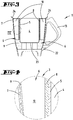
- the vessel wall 3 of the preparation vessel 1 is as in the Figures 3 to 6 Shown in more detail, has a double wall and has an inner wall 5 facing the preparation space 4 and an outer wall 7 pointing outwards. Between the inner wall 5 and the outer wall 7, an intermediate space 6 is formed.
- the intermediate space 6 has a cooling device 8 which is in heat-conducting contact with the inner wall 5.
- the cooling device 8 here consists of a plurality of Peltier elements which surround the preparation space 4 of the preparation vessel 1 in a ring.
- phase change material 9 which has a volume which approximately corresponds to the volume of the preparation space 4.
- the phase change material 9 also engages between the cooling fins 11 of the heat sink 10 and thus ensures optimum heat dissipation from the heat sink 10 or the cooling device 8 and the inner wall 5 of the preparation vessel 1.
- the phase change material 9 preferably has a transition temperature below the room temperature, for example in the range of 10 ° C. If necessary, two different phase change materials 9 can be used simultaneously in order to expand the operating range of the cooled preparation vessel 1.
- the cooling capacity and efficiency of the cooling device 8 designed here as Peltier elements are heavily dependent on a temperature difference between the warm and the cold side of the cooling device 8.
- the cooling performance and efficiency of the Peltier elements can be significantly increased in comparison to indoor air-cooled Peltier elements at the same cold side temperature.
- a higher temperature difference between the warm and the cold side of the cooling device 8 may be necessary, which could not be achieved with conventional, air-cooled Peltier element systems.
- the phase change material 9 is preferably pre-cooled. This can be done either by storing the preparation vessel 1 in a cooling room or refrigerator, or by heating a medium, such as water, within the preparation room 4 of the preparation vessel 1, so that heat stored in the phase change material 9 to that in the preparation room 4 Water can be passed.
Landscapes
- Engineering & Computer Science (AREA)
- Food Science & Technology (AREA)
- Mechanical Engineering (AREA)
- Chemical & Material Sciences (AREA)
- Life Sciences & Earth Sciences (AREA)
- Polymers & Plastics (AREA)
- Physics & Mathematics (AREA)
- Thermal Sciences (AREA)
- General Engineering & Computer Science (AREA)
- Chemical Kinetics & Catalysis (AREA)
- Manufacturing & Machinery (AREA)
- Devices That Are Associated With Refrigeration Equipment (AREA)
Abstract
Description
- Die Erfindung betrifft ein Zubereitungsgefäß, insbesondere für eine Küchenmaschine, wobei das Zubereitungsgefäß eine Gefäßwandung und einen von der Gefäßwandung umgebenen Zubereitungsraum aufweist, wobei der Gefäßwandung eine die Gefäßwandung wärmeleitend kontaktierende Kühleinrichtung zur Kühlung eines in dem Zubereitungsraum vorhandenen Zubereitungsgutes zugeordnet ist.
- Des Weiteren betrifft die Erfindung eine Küchenmaschine mit einem Basisgerät und einem mit dem Basisgerät verbindbaren Zubereitungsgefäß, wobei das Basisgerät und das Zubereitungsgefäß korrespondierende elektrische Kontakte zur Energieversorgung elektrischer Verbraucher des Zubereitungsgefäßes durch eine Energiequelle des Basisgerätes aufweisen.
- Zubereitungsgefäße sowie Küchenmaschinen mit solchen Zubereitungsgefäßen sind im Stand der Technik bekannt.
- Die Veröffentlichung
WO 2007/135130 A1 offenbart beispielsweise eine Küchenmaschine, nämlich eine Speiseeisbereitungs-Vorrichtung, mit einer einer Gefäßwandung zugeordneten Kühleinrichtung in Form eines Peltier-Elements. Das Peltier-Element ist mit seiner kühlenden Seite mit der Gefäßwandung verbunden und wird auf seiner warmen Seite mittels eines Kühlkreislaufes gekühlt, in welchem ein Wärmeübertragungsmedium geführt wird. Dem Kühlkreislauf kann zur Kühlung ein weiteres Peltier-Element zugeordnet sein. - Obwohl sich eine derartige Küchenmaschine zur Zubereitung von beispielsweise Eiscreme oder anderen kühlen beziehungsweise gefrorenen Zubereitungsgütern eignet, ist diese durch die Bereitstellung eines separaten Kühlkreislaufes, in welchem ein Wärmeübertragungsmedium umgewälzt wird, aufwendig in der Herstellung und relativ groß.
- Es ist daher Aufgabe der vorliegenden Erfindung, ein Zubereitungsgefäß und auch eine Küchenmaschine vorzuschlagen, welche eine Kühlung des Zubereitungsgefäßes ermöglichen, ohne das Zubereitungsgefäß beziehungsweise die Küchenmaschine mit einem Kühlkreislauf, welcher eine elektrische Pumpe benötigt, ausstatten zu müssen.
- Zur Lösung dieser Aufgabe wird zunächst vorgeschlagen, dass die Gefäßwandung des Zubereitungsgefäßes zumindest in einem Teilbereich doppelwandig mit einer den Zubereitungsraum begrenzenden Innenwandung und einer separat dazu ausgebildeten, durch einen Zwischenraum von der Innenwandung beabstandeten Außenwandung ausgebildet ist, wobei der Zwischenraum in eine Richtung von dem Zubereitungsraum zu der Außenwandung betrachtet die Kühleinrichtung und ein zwischen der Kühleinrichtung und der Außenwandung befindliches Phasenwechselmaterial (PCM, Phase Change Material) aufweist.
- Erfindungsgemäß verfügt das Zubereitungsgefäß nun über eine doppelwandige Gefäßwandung, in welcher einerseits die Kühleinrichtung zur Kühlung der Innenwandung, und andererseits ein Phasenwechselmaterial, zum Wegleiten der Wärme von der Kühleinrichtung zu der Außenwandung des Zubereitungsgefäßes angeordnet sind. In Betrachtungsrichtung von dem Zubereitungsraum zu der Außenseite des Zubereitungsgefäßes weist die Gefäßwandung hintereinander zunächst die Innenwandung, dann die Kühleinrichtung, danach das Phasenwechselmaterial und schließlich die Außenwandung auf, wobei die Kühleinrichtung und das Phasenwechselmaterial sich innerhalb des Zwischenraums der doppelwandigen Gefäßwandung befinden. Die Kühleinrichtung leitet die aus dem Zubereitungsraum übernommene Wärmeenergie an das Phasenwechselmaterial weiter, welches die Wärmeenergie aufgrund der für Phasenwechselmaterialien hohen spezifischen Wärmekapazität aufnehmen kann. Im Gegensatz zum Stand der Technik ist es nicht mehr erforderlich, zur Kühlung der Kühleinrichtung beziehungsweise des Zubereitungsraums einen Kühlkreislauf auszubilden, der durch eine elektrische Pumpe angetrieben wird. Vielmehr kann sowohl die Kühleinrichtung, als auch das Phasenwechselmaterial, in die Gefäßwandung selbst eingebracht werden, nämlich in den Zwischenraum zwischen einer Innenwandung und einer Außenwandung der Gefäßwandung. Somit kann das erfindungsgemäße Zubereitungsgefäß einerseits ein solches sein, welches zur Verbindung mit einem Basisgerät einer Küchenmaschine ausgebildet ist und elektrische Energie für beispielsweise die Kühleinrichtung von einer Energiequelle des Basisgerätes der Küchenmaschine bezieht, oder ein Zubereitungsgefäß, welches als "stand alone Gerät" ausgebildet ist und über eine eigene Energieversorgung verfügt, so dass das Zubereitungsgefäß als solches ohne Zuhilfenahme anderer Geräte einsatzbereit ist.
- Phasenwechselmaterialien, auch Latentwärmespeichermaterialien genannt, besitzen spezifische Wärmekapazitäten von größer als 2 kJ/(kg K). Die Phasenwechselmaterialien zeichnen sich dadurch aus, dass diese Wärmeenergie verlustarm und über lange Zeit speichern können. Die latente Schmelzwärme, d.h. die absorbierbare Wärmeenergiemenge, ist im Bereich der für das jeweilige Phasenwechselmaterial charakteristischen Umwandlungstemperatur wesentlich größer als die Wärmeenergiemenge, die aufgrund der spezifischen Wärmekapazität des Materials außerhalb des Phasenumwandlungseffekts gespeichert werden kann. In Alltagsgegenständen werden diese Phasenwechselmaterialien beispielsweise in Wärmekissen und Kühlakkus verwendet. Die Wärmespeichermedien werden unter Nutzung ihres Phasenübergangs von fest zu flüssig, und umgekehrt, genutzt. Beim Aufladen des Wärmespeichermediums mit Wärmeenergie wird das Wärmespeichermedium geschmolzen, wobei sehr viel Wärmeenergie aufgenommen werden kann. Die Freigabe der gespeicherten Wärmeenergiemenge findet bei dem Erstarren des Wärmespeichermediums statt, wobei die zuvor aufgenommene große Wärmemenge als Erstarrungswärme wieder an die Umgebung abgegeben wird. Der Vorteil der Phasenwechselmaterialien ist, dass in einem kleinen durch die Umwandlungstemperatur vorgegebenen Temperaturbereich eine große Menge Wärmeenergie in einer relativ geringen Masse gespeichert werden kann. Hinzu kommt, dass die Wärmeenergie aufgrund der Nutzung metastabiler Zustände des Wärmespeichermediums auch ohne oder mit geringerer thermischer Isolierung als bei Materialien, bei welchen kein Umwandlungseffekt im Hinblick auf eine Wärmespeicherung genutzt wird, und sehr verlustarm gespeichert werden kann. Die Freigabe der gespeicherten Wärmeenergie aus dem Phasenwechselmaterial kann dann wiederum durch beispielsweise Herunterkühlen des Zubereitungsgefäßes in einem Kühlschrank oder durch Aufheizen eines in dem Zubereitungsraum befindlichen Mediums, wie z.B. Wasser, erreicht werden.
- Es wird vorgeschlagen, dass das Phasenwechselmaterial durch Zwischenanordnung der Kühleinrichtung von der Innenwandung beabstandet ist. Gemäß dieser Ausführung weist das Phasenwechselmaterial vorzugsweise keinen direkten Kontakt mit der Innenwandung des Zubereitungsgefäßes auf, so dass die Wärmeübertragung aus dem Zubereitungsraum auf das Phasenwechselmaterial ausschließlich über die Kühleinrichtung erfolgt. Grundsätzlich ist es jedoch nicht ausgeschlossen, dass die Gefäßwandung sowohl Teilbereiche aufweist, an welchen die Innenwandung direkt von dem Phasenwechselmaterial kontaktiert ist und Teilbereiche, an welchen zwischen dem Phasenwechselmaterial und der Innenwandung zumindest ein Teilbereich der Kühleinrichtung angeordnet ist.
- Insbesondere wird vorgeschlagen, dass die Kühleinrichtung ein Peltier-Element ist. Die Kühleinrichtung kann aus mehreren in Umfangsrichtung der Gefäßwandung hintereinander angeordneten Peltier-Elementen bestehen, so dass die Mehrzahl von Peltier-Elementen den Zubereitungsraum ringförmig umgibt. Die Peltier-Elemente sind wärmeleitfähig mit der Innenwandung des Zubereitungsgefäßes in Kontakt, dazu kann gegebenenfalls ein Wärmeleitgel oder eine Wärmeleitpaste angewendet werden. Ein Peltier-Element besteht aus zwei Keramik-Platten, die über p- und n-dotierte Halbleiterelemente verbunden sind, wobei die p- und n-dotierten Halbleiterelemente abwechselnd paarweise über Kontaktstellen miteinander verschaltet sind. Leitet man einen Strom durch zwei hintereinanderliegende Kontaktstellen der p- und n-Leiter, so wird an einer Kontaktstelle Wärmeenergie aufgenommen und an der anderen Kontaktstelle Wärmeenergie abgegeben. Dabei hängt es von der Stromrichtung ab, welche Seite des Peltier-Elements dann kalt wird und welche Seite warm wird. Sofern die warme Seite des Peltier-Elements dann gekühlt wird, hier beispielsweise mittels des Phasenwechselmaterials, welches der warmen Seite Wärmeenergie entzieht, wird die entgegengesetzte kalte Seite des Peltier-Elements weiter heruntergekühlt. Damit kann eine noch geringere Temperatur innerhalb des Zubereitungsraums des Zubereitungsgefäßes erreicht werden. Für eine Regeneration des Phasenwechselmaterials, d.h. zur Abgabe der aufgenommenen Wärmeenergie, kann vorzugsweise die Stromrichtung durch das Peltier-Element geändert werden, so dass die wärmeabgebende Seite dann in Kontakt mit der Innenwandung steht und dort in ein kühles Medium, beispielsweise kaltes Wasser, abgegeben werden kann. Das Phasenwechselmaterial steht sodann wieder für die Aufnahme von Wärmeenergie zur Verfügung. Alternativ ist es jedoch auch möglich, das Zubereitungsgefäß insgesamt beispielsweise in einen Kühlraum oder einen Kühlschrank zu stellen, um das Phasenwechselmaterial herunterzukühlen. Alternativ zu der Ausbildung als Peltier-Element kann die Kühleinrichtung in einem besonders einfachen Fall jedoch auch einfach ein Kühlkörper, beispielsweise mit Kühlrippen, sein, der die Innenwandung des Zubereitungsgefäßes kontaktiert. Dieser Kühlkörper kann beispielsweise einteilig und/ oder materialeinheitlich mit der Innenwandung des Zubereitungsgefäßes ausgebildet sein und besonders bevorzugt aus einem gut wärmeleitenden Material, insbesondere einem lebensmittelechten Metall, bestehen.
- In Kombination mit einer als Peltier-Element ausgebildeten Kühleinrichtung wird zudem vorgeschlagen, dass auf der von der Innenwandung abgewandten Seite des Peltier-Elements ein Kühlkörper angeordnet ist. Auch in diesem Fall kann der Kühlkörper beispielsweise ein Kühlrippen aufweisender Kühlkörper sein. Der Kühlkörper dient zur vorteilhaften Ableitung der Wärmeenergie von der warmen Seite des Peltier-Elements, so dass die warme Seite des Peltier-Elementes heruntergekühlt wird und dadurch die kühle Seite des Peltier-Elements, welche an der Innenwandung des Zubereitungsgefäßes anliegt, noch kälter werden kann. Es empfiehlt sich, dass der Kühlkörper eine möglichst große Kühlfläche zur Verfügung stellt, beispielsweise über eine Vielzahl von nebeneinander angeordneten Kühlrippen, zwischen welchen das Phasenwechselmaterial angeordnet ist. Die Übertragung von Wärmeenergie ist somit optimal möglich.
- Des Weiteren wird vorgeschlagen, dass das Phasenwechselmaterial eine spezifische Wärmekapazität von größer als 2 kJ/ (kg K) aufweist. Insbesondere kann das Phasenwechselmaterial eine spezifische Wärmekapazität von größer als 4 kJ/ (kg K) aufweisen. Dadurch kann innerhalb des Zwischenraums eine möglichst große Menge Wärmeenergie gespeichert werden, welche entsprechend dann dem Zubereitungsraum des Zubereitungsgefäßes entzogen wird. Das Phasenwechselmaterial kann ebenfalls als Phasenwechselmaterial-Polymer-Zusammensetzung ausgebildet sein. Die für die Zusammensetzung verwendeten Polymere sind vorzugsweise Polyethylene, insbesondere Low Density Polyethylene (LDPE), beispielsweise aus Diblock- und Triblock-Copolymeren. Diese Zusammensetzungen sind vorteilhaft ausschwitzarm beziehungsweise ausschwitzfrei, mechanisch fest und wärmeformbeständig und weisen eine verbesserte Wärmeleitfähigkeit auf. Des Weiteren kann als Phasenwechselmaterial auch Wasser verwendet werden, welches eine besonders hohe spezifische Wärmekapazität von 4,182 kJ/ (kg K) aufweist. Beispielsweise wird beim Gefrieren von Wasser, d.h. dem Phasenübergang von flüssig zu fest, ungefähr eine so große Wärmemenge frei wie zum Erwärmen derselben Menge Wasser von 0°C auf 80°C benötigt wird. Neben Wasser kommen auch andere Phasenwechselmaterialien in Frage, beispielsweise Dikaliumhydrogenphosphat-Hexahydrat oder Natriumacetat-Trihydrat.
- In diesem Zusammenhang wird insbesondere vorgeschlagen, dass das Phasenwechselmaterial eine Umwandlungstemperatur aufweist, die größer ist als -10°C und geringer ist als 25°C, insbesondere größer ist als 5°C und geringer ist als 20°C. Diese Umwandlungstemperaturen liegen vorteilhaft in demjenigen Temperaturbereich, der bei in dem Zubereitungsraum zu kühlenden Speisen vorteilhaft ist. Es können Umwandlungstemperaturen kleiner als 5°C vorteilhaft sein, insbesondere auch negative Umwandlungstemperaturen, um beispielsweise ein Gefrieren von Zubereitungsgut innerhalb des Zubereitungsraumes zu erreichen. In diesem Fall kann das Phasenwechselmaterial bevorzugt auf der Basis von Paraffin oder Salz hergestellt sein, so dass die Umwandlungstemperatur beispielsweise unterhalb von 0°C liegt, vorzugsweise bis hin zu minus 10°C.
- Des Weiteren wird vorgeschlagen, dass der Zwischenraum mehrere Phasenwechselmaterialien mit zueinander verschiedenen Umwandlungstemperaturen aufweist. Dadurch kann der Betriebsbereich des gekühlten Zubereitungsgefäßes vorteilhaft vergrößert werden.
- Des Weiteren wird es als vorteilhaft vorgeschlagen, wenn ein Volumen des in dem Zwischenraum befindlichen Phasenwechselmaterials ungefähr so groß ist wie ein Volumen des Zubereitungsraums. Insbesondere empfiehlt es sich, dass das Volumen des Phasenwechselmaterials 0,75 mal bis 1,25 mal so groß ist wie das Volumen des Zubereitungsraums. Diese Volumenverhältnisse haben sich als besonders vorteilhaft erwiesen, um innerhalb des Zubereitungsraums befindliches Zubereitungsgut schnell und effektiv zu kühlen. Bei einem Zubereitungsraum, welcher beispielsweise ein Volumen von 1,2 l aufweist, empfiehlt sich ein Volumen des Phasenwechselmaterials in einem Bereich von 1,0 l bis 1,3 l.
- Schließlich wird neben dem zuvor beschriebenen Zubereitungsgefäß auch eine Küchenmaschine vorgeschlagen, welche ein Basisgerät und ein mit dem Basisgerät verbindbares Zubereitungsgefäß aufweist, wobei das Basisgerät und das Zubereitungsgefäß korrespondierende elektrische Kontakte zur Energieversorgung elektrischer Verbraucher des Zubereitungsgefäßes durch eine Energiequelle des Basisgerätes aufweisen, und wobei das Zubereitungsgefäß nach einer der zuvor beschriebenen Ausführungsformen ausgebildet ist und die Kühleinrichtung ein elektrischer Verbraucher des Zubereitungsgefäßes ist.
- Die Küchenmaschine kann beispielsweise ein kombiniertes Koch-Mix-Gerät sein, welches eine Heizeinrichtung für das Zubereitungsgefäß und einen Elektromotor zum Antrieb eines in das Zubereitungsgefäß hineinragenden Rührwerks aufweist. Das Zubereitungsgefäß und das Basisgerät weisen korrespondierende elektrische Kontakte auf, welche bei Verbindung des Zubereitungsgefäßes mit dem Basisgerät eine Energieversorgung der elektrischen Verbraucher des Zubereitungsgefäßes über das Basisgerät ermöglichen. Ein elektrischer Verbraucher des Zubereitungsgefäßes ist dabei das zuvor beschriebene Peltier-Element, welches zur Kühlung der Gefäßwandung beziehungsweise eines innerhalb des Zubereitungsraumes befindlichen Zubereitungsgutes verwendet wird.
- Im Folgenden wird die Erfindung anhand von Ausführungsbeispielen näher erläutert. Es zeigen:
- Fig. 1
- eine erfindungsgemäße Küchenmaschine mit einem erfindungsgemäßen Zubereitungsgefäß,
- Fig. 2
- die Küchenmaschine mit dem Zubereitungsgefäß in einer Seitenansicht,
- Fig. 3
- das Zubereitungsgefäß in Alleinstellung in einem Längsschnitt,
- Fig. 4
- einen vergrößerten Teilbereich einer Gefäßwandung des Zubereitungsgefäßes,
- Fig. 5
- einen Querschnitt des Zubereitungsgefäßes,
- Fig. 6
- einen vergrößerten Teilbereich des Zubereitungsgefäßes gemäß
Figur 5 . -
Figur 1 zeigt lediglich beispielhaft eine elektromotorisch betriebene Küchenmaschine 2, welche hier als kombiniertes Koch-Mix-Gerät ausgebildet ist. Die Küchenmaschine 2 verfügt über ein Basisgerät mit einem Gehäuse 12, mit welchem lösbar ein Zubereitungsgefäß 1 verbunden ist. Das Gehäuse 12 weist ein Display 16 und einen Schalter 17 auf, über welche ein Nutzer die Küchenmaschine 2 bedienen kann. Über das als Touchscreen ausgebildete Display 16 sowie den Schalter 17 kann der Nutzer beispielsweise eine Rezeptauswahl tätigen und Eingaben für die Steuerung der Küchenmaschine 2 vornehmen. An dem Gehäuse 12 sind des Weiteren Verriegelungselemente 19 angeordnet, die der Verriegelung des Zubereitungsgefäßes 1 mit einem Deckelelement 14 dienen. Die Verriegelungselemente 19 sind hier um eine Längsachse rotierbare Verriegelungswalzen, die über einen Rand 24 des Zubereitungsgefäßes 1 (sieheFigur 3 ) und des Deckelelementes 14 greifen, um diese miteinander zu verriegeln. Das Deckelelement 14 weist des Weiteren eine zentrale Öffnung 15 auf, durch welche ein Nutzer Zutaten in das Zubereitungsgefäß 1 geben kann und einen Zubereitungszustand des Zubereitungsgutes beobachten kann. Während eines Zubereitungsvorgangs ist die zentrale Öffnung 15 üblicherweise mit einem Messbecher (nicht dargestellt) verschlossen, so dass Zubereitungsgut nicht aus dem Zubereitungsgefäß 1 herausspritzen kann. Die Küchenmaschine 2 weist des Weiteren zur Energieversorgung ein Elektrokabel 18 auf, welches in üblicher Art und Weise mit der Energieversorgung eines Haushalts verbunden werden kann. - Das Zubereitungsgefäß 1 ist hier beispielsweise als Rührgefäß ausgebildet. Wie in
Figur 2 dargestellt, weist dieses ein Rührwerk 20 auf, welches durch eine Bodenöffnung 23 (sieheFigur 3 ) des Zubereitungsgefäßes 1 in einen Zubereitungsraum 4 des Zubereitungsgefäßes 1 ragt. Das Rührwerk 20 ist mit einem elektromotorischen Drehantrieb der Küchenmaschine 2 verbunden. Das Rührwerk 20 verfügt über eine Mehrzahl von Messern 21, die zum Zerkleinern oder Mischen von Zubereitungsgut geeignet sind. An dem Zubereitungsgefäß 1 ist des Weiteren bodenseitig ein Fußteil 22 angeordnet, welches gleichzeitig der Fixierung des Rührwerks 20 an dem Zubereitungsgefäß 1 dient. An einer Gefäßwandung 3 des Zubereitungsgefäßes 1 ist des Weiteren ein Griff 13 angeordnet, an welchem ein Nutzer angreifen kann, um das Zubereitungsgefäß 1 beispielsweise aus der Küchenmaschine 2 zu entnehmen oder dieses wieder in die Küchenmaschine 2 einzusetzen. - Die Gefäßwandung 3 des Zubereitungsgefäßes 1 ist wie in den
Figuren 3 bis 6 näher dargestellt doppelwandig ausgebildet und verfügt über eine dem Zubereitungsraum 4 zugewandte Innenwandung 5 und eine nach außen weisende Außenwandung 7. Zwischen der Innenwandung 5 und der Außenwandung 7 ist ein Zwischenraum 6 ausgebildet. Der Zwischenraum 6 weist eine Kühleinrichtung 8 auf, die in wärmeleitendem Kontakt mit der Innenwandung 5 steht. Die Kühleinrichtung 8 besteht hier aus einer Mehrzahl von Peltier-Elementen, welche den Zubereitungsraum 4 des Zubereitungsgefäßes 1 ringförmig umgeben. - An der von der Innenwandung 5 abgewandten Seite der Kühleinrichtung 8 schließen sich eine Mehrzahl von Kühlkörpern 10 an, die jeweils mehrere Kühlrippen 11 aufweisen. In dem Zwischenraum 6 befindet sich des Weiteren, angrenzend an sowohl die Kühleinrichtung 8 als auch den Kühlkörper 10, ein Phasenwechselmaterial 9, welches ein Volumen aufweist, das ungefähr dem Volumen des Zubereitungsraums 4 entspricht.
- Insbesondere in den
Figuren 5 und 6 ist erkennbar, wie das Phasenwechselmaterial 9 auch zwischen die Kühlrippen 11 des Kühlkörpers 10 greift und somit für eine optimale Wärmeabfuhr von dem Kühlkörper 10 beziehungsweise der Kühleinrichtung 8 und der Innenwandung 5 des Zubereitungsgefäßes 1 sorgt. Um in dem Zubereitungsraum 4 befindliches Zubereitungsgut auf eine Temperatur unterhalb der Raumtemperatur kühlen zu können, weist das Phasenwechselmaterial 9 vorzugsweise eine Umwandlungstemperatur unterhalb der Raumtemperatur auf, hier beispielsweise im Bereich von 10°C. Gegebenenfalls können zwei verschiedene Phasenwechselmaterialien 9 gleichzeitig angewendet werden, um den Betriebsbereich des gekühlten Zubereitungsgefäßes 1 zu erweitern. - Die Kühlleistung und Effizienz der hier als Peltier-Elemente ausgebildeten Kühleinrichtung 8 sind stark von einer Temperaturdifferenz zwischen der warmen und der kalten Seite der Kühleinrichtung 8 abhängig. Durch die Nutzung des Phasenwechselmaterials 9 auf der warmen Seite der Peltier-Elemente, können die Kühlleistung und Effizienz der Peltier-Elemente im Vergleich zu raumluftgekühlten Peltier-Elementen bei gleicher Kaltseitentemperatur deutlich erhöht werden. Insbesondere für beispielsweise die Zubereitung von Speiseeis, kann eine höhere Temperaturdifferenz zwischen der warmen und der kalten Seite der Kühleinrichtung 8 erforderlich sein, die mit herkömmlichen, raumluftgekühlten Peltier-Element-Systemen nicht erreicht werden könnte.
- Um die Temperaturdifferenz möglichst groß zu machen, wird das Phasenwechselmaterial 9 vorzugsweise vorgekühlt. Dies kann entweder durch die Lagerung des Zubereitungsgefäßes 1 in einem Kühlraum oder Kühlschrank geschehen, oder durch das Aufheizen eines Mediums, wie z.B. Wasser, innerhalb des Zubereitungsraums 4 des Zubereitungsgefäßes 1, so dass in dem Phasenwechselmaterial 9 gespeicherte Wärme auf das in dem Zubereitungsraum 4 befindliche Wasser übergeben werden kann.
-
- 1
- Zubereitungsgefäß
- 2
- Küchenmaschine
- 3
- Gefäßwandung
- 4
- Zubereitungsraum
- 5
- Innenwandung
- 6
- Zwischenraum
- 7
- Außenwandung
- 8
- Kühleinrichtung
- 9
- Phasenwechselmaterial
- 10
- Kühlkörper
- 11
- Kühlrippe
- 12
- Gehäuse
- 13
- Griff
- 14
- Deckelelement
- 15
- Öffnung
- 16
- Display
- 17
- Schalter
- 18
- Elektrokabel
- 19
- Verriegelungselement
- 20
- Rührwerk
- 21
- Messer
- 22
- Fußteil
- 23
- Bodenöffnung
- 24
- Rand
Claims (9)
- Zubereitungsgefäß (1), insbesondere für eine Küchenmaschine (2), wobei das Zubereitungsgefäß (1) eine Gefäßwandung (3) und einen von der Gefäßwandung (3) umgebenen Zubereitungsraum (4) aufweist, wobei der Gefäßwandung (3) eine die Gefäßwandung (3) wärmeleitend kontaktierende Kühleinrichtung (8) zur Kühlung eines in dem Zubereitungsraum (4) vorhandenen Zubereitungsgutes zugeordnet ist, dadurch gekennzeichnet, dass die Gefäßwandung (3) zumindest in einem Teilbereich doppelwandig mit einer den Zubereitungsraum (4) begrenzenden Innenwandung (5) und einer separat dazu ausgebildeten, durch einen Zwischenraum (6) von der Innenwandung (5) beabstandeten Außenwandung (7) ausgebildet ist, wobei der Zwischenraum (6) in eine Richtung von dem Zubereitungsraum (4) zu der Außenwandung (7) betrachtet die Kühleinrichtung (8) und ein zwischen der Kühleinrichtung (8) und der Außenwandung (7) befindliches Phasenwechselmaterial (PCM, Phase Change Material) (9) aufweist.
- Zubereitungsgefäß (1) nach Anspruch 1, dadurch gekennzeichnet, dass das Phasenwechselmaterial (9) durch Zwischenanordnung der Kühleinrichtung (8) von der Innenwandung (5) beabstandet ist.
- Zubereitungsgefäß (1) nach Anspruch 1 oder 2, dadurch gekennzeichnet, dass die Kühleinrichtung (8) ein Peltier-Element ist.
- Zubereitungsgefäß (1) nach Anspruch 3, dadurch gekennzeichnet, dass auf der von der Innenwandung (5) abgewandten Seite des Peltier-Elements ein Kühlkörper (10), insbesondere ein Kühlrippen (11) aufweisender Kühlkörper (10), angeordnet ist.
- Zubereitungsgefäß (1) nach einem der vorhergehenden Ansprüche, dadurch gekennzeichnet, dass das Phasenwechselmaterial (9) eine spezifische Wärmekapazität von größer als 2 kJ/ (kg K), insbesondere von größer als 4 kJ/ (kg K), aufweist.
- Zubereitungsgefäß (1) nach Anspruch 5, dadurch gekennzeichnet, dass das Phasenwechselmaterial eine Umwandlungstemperatur aufweist, die größer ist als -10°C und geringer ist als 25°C, insbesondere größer ist als 5°C und geringer ist als 20°C.
- Zubereitungsgefäß (1) nach Anspruch 5 oder 6, dadurch gekennzeichnet, dass der Zwischenraum (6) mehrere Phasenwechselmaterialien (9) mit zueinander verschiedenen Umwandlungstemperaturen aufweist.
- Zubereitungsgefäß (1) nach einem der vorhergehenden Ansprüche, dadurch gekennzeichnet, dass ein Volumen des Phasenwechselmaterials (9) ungefähr so groß ist wie ein Volumen des Zubereitungsraums (4), insbesondere 0,75 mal bis 1,25 mal so groß ist wie das Volumen des Zubereitungsraums (4).
- Küchenmaschine (2) mit einem Basisgerät (12) und einem mit dem Basisgerät (12) verbindbaren Zubereitungsgefäß (1), wobei das Basisgerät (12) und das Zubereitungsgefäß (1) korrespondierende elektrische Kontakte zur Energieversorgung elektrischer Verbraucher des Zubereitungsgefäßes (1) durch eine Energiequelle des Basisgerätes (12) aufweisen, dadurch gekennzeichnet, dass das Zubereitungsgefäß (1) nach einem der vorhergehenden Ansprüche ausgebildet ist und die Kühleinrichtung (8) ein elektrischer Verbraucher des Zubereitungsgefäßes (1) ist.
Priority Applications (1)
| Application Number | Priority Date | Filing Date | Title |
|---|---|---|---|
| PL19184565T PL3590351T3 (pl) | 2018-07-05 | 2019-07-05 | Naczynie do przyrządzania z urządzeniem chłodzącym |
Applications Claiming Priority (1)
| Application Number | Priority Date | Filing Date | Title |
|---|---|---|---|
| DE102018116336.3A DE102018116336A1 (de) | 2018-07-05 | 2018-07-05 | Zubereitungsgefäß mit einer Kühleinrichtung |
Publications (2)
| Publication Number | Publication Date |
|---|---|
| EP3590351A1 true EP3590351A1 (de) | 2020-01-08 |
| EP3590351B1 EP3590351B1 (de) | 2021-03-03 |
Family
ID=67253669
Family Applications (1)
| Application Number | Title | Priority Date | Filing Date |
|---|---|---|---|
| EP19184565.0A Active EP3590351B1 (de) | 2018-07-05 | 2019-07-05 | Zubereitungsgefäss mit einer kühleinrichtung |
Country Status (6)
| Country | Link |
|---|---|
| US (1) | US11298667B2 (de) |
| EP (1) | EP3590351B1 (de) |
| CN (1) | CN110680211A (de) |
| DE (1) | DE102018116336A1 (de) |
| ES (1) | ES2862389T3 (de) |
| PL (1) | PL3590351T3 (de) |
Cited By (13)
| Publication number | Priority date | Publication date | Assignee | Title |
|---|---|---|---|---|
| US11617378B2 (en) | 2020-12-31 | 2023-04-04 | Sharkninja Operating Llc | Micro puree machine |
| US11672382B2 (en) | 2020-12-31 | 2023-06-13 | Sharkninja Operating Llc | Micro puree machine |
| US11832767B2 (en) | 2020-12-31 | 2023-12-05 | Sharkninja Operating Llc | Micro puree machine |
| US11864690B2 (en) | 2020-12-31 | 2024-01-09 | Sharkninja Operating Llc | Micro puree machine |
| USD1021533S1 (en) | 2022-05-09 | 2024-04-09 | Sharkninja Operating Llc | User interface for a micro puree machine |
| USD1021520S1 (en) | 2022-05-09 | 2024-04-09 | Sharkninja Operating Llc | Housing for a micro puree machine |
| USD1033134S1 (en) | 2022-07-05 | 2024-07-02 | Sharkninja Operating Llc | Blade for a micro puree machine |
| US12064059B2 (en) | 2022-05-18 | 2024-08-20 | Sharkninja Operating Llc | Lid and blade assembly for a micro puree machine |
| USD1041252S1 (en) | 2020-12-31 | 2024-09-10 | Sharkninja Operating Llc | Bowl for a micro puree machine |
| USD1052339S1 (en) | 2022-05-09 | 2024-11-26 | Sharkninja Operating Llc | Beaker for a micro puree machine |
| USD1052340S1 (en) | 2022-05-09 | 2024-11-26 | Sharkninja Operating Llc | Container for a micro puree machine |
| US12575698B2 (en) | 2021-07-12 | 2026-03-17 | Sharkninja Operating Llc | Micro puree machine with selectable food processing routines and automated motor control |
| US12593941B2 (en) | 2022-05-18 | 2026-04-07 | Sharkninja Operating Llc | Micro puree machine with partial depth processing |
Families Citing this family (15)
| Publication number | Priority date | Publication date | Assignee | Title |
|---|---|---|---|---|
| JP6949730B2 (ja) | 2015-06-02 | 2021-10-13 | エフ エム シー コーポレーションFmc Corporation | 置換環状アミドおよび除草剤としてのそれらの使用 |
| SG11201908640TA (en) | 2017-03-21 | 2019-10-30 | Fmc Corp | Pyrrolidinones and a process to prepare them |
| US10945550B2 (en) * | 2018-03-01 | 2021-03-16 | The Steelstone Group Llc | Cooling multi-cooker |
| USD964803S1 (en) | 2020-06-23 | 2022-09-27 | Whirlpool Corporation | Mixing bowl |
| US12193454B2 (en) | 2020-06-23 | 2025-01-14 | Whirlpool Corporation | Ice cream maker assembly |
| US20220001344A1 (en) * | 2020-07-06 | 2022-01-06 | Haier Us Appliance Solutions, Inc. | Actively-cooled blender appliance |
| USD984851S1 (en) * | 2020-07-16 | 2023-05-02 | Harbour Star International Limited | Container |
| US11641978B2 (en) | 2020-12-31 | 2023-05-09 | Sharkninja Operating Llc | Micro puree machine |
| US12016496B2 (en) | 2020-12-31 | 2024-06-25 | Sharkninja Operating Llc | Micro puree machine |
| USD985331S1 (en) | 2020-12-31 | 2023-05-09 | Sharkninja Operating Llc | Housing for a micro puree machine |
| US12064056B2 (en) | 2020-12-31 | 2024-08-20 | Sharkninja (Hong Kong) Company Limited | Micro puree machine |
| USD983603S1 (en) | 2020-12-31 | 2023-04-18 | Sharkninja Operating Llc | Blade for a micro puree machine |
| CN112891217A (zh) * | 2021-01-25 | 2021-06-04 | 刘明锋 | 一种健康管理用中药专用搅拌杯 |
| USD1028619S1 (en) | 2022-01-13 | 2024-05-28 | Whirlpool Corporation | Stand mixer |
| USD1063505S1 (en) | 2022-10-25 | 2025-02-25 | Whirlpool Corporation | Stand mixer |
Citations (11)
| Publication number | Priority date | Publication date | Assignee | Title |
|---|---|---|---|---|
| GB2144208A (en) * | 1983-06-14 | 1985-02-27 | Nippon Light Metal Co | Device for making frozen confections |
| EP0133844A1 (de) * | 1983-08-01 | 1985-03-06 | BREVETTI GAGGIA S.p.A. | Speiseeisbereiter mit Peltierkühlaggregat |
| JPS60160847A (ja) * | 1984-01-31 | 1985-08-22 | Nippon Sanso Kk | アイスクリ−ム製造機 |
| DE3921115A1 (de) * | 1989-06-28 | 1991-01-10 | Braun Ag | Universalkuechenmaschine |
| GB2304179A (en) * | 1995-08-11 | 1997-03-12 | Fraser Milne Ltd | Cooling apparatus |
| WO2006010538A1 (de) * | 2004-07-23 | 2006-02-02 | BSH Bosch und Siemens Hausgeräte GmbH | Thermoelektrisches kühlgerät |
| WO2007135130A1 (de) | 2006-05-23 | 2007-11-29 | Vorwerk & Co. Interholding Gmbh | Verfahren zum betreiben eines zur vereisung seines inhaltes geeigneten behältnis sowie speiseeisbereitungs-vorrichtung |
| US20130221013A1 (en) * | 1997-04-07 | 2013-08-29 | J. Bruce Kolowich | Thermal receptacle with phase change material |
| CN205358065U (zh) * | 2014-03-11 | 2016-07-06 | 布瑞威利私人有限公司 | 用于食物处理器的带齿轮的心轴 |
| US20160215194A1 (en) * | 2015-01-26 | 2016-07-28 | Trent University | Food/beverage container with thermal control |
| EP3501353A1 (de) * | 2017-12-12 | 2019-06-26 | Vorwerk & Co. Interholding GmbH | Zubereitungsgefäss für eine küchenmaschine |
Family Cites Families (17)
| Publication number | Priority date | Publication date | Assignee | Title |
|---|---|---|---|---|
| BR8505264A (pt) * | 1985-10-16 | 1987-05-26 | Simone Teixeira Lovera | Maquina de uso domestico para congelar e homogeneizar sorvete |
| NL9000059A (nl) * | 1990-01-10 | 1991-08-01 | Philips Nv | Blender. |
| US5255520A (en) * | 1991-12-20 | 1993-10-26 | Refir Technologies | Advanced thermoelectric heating and cooling system |
| US5842353A (en) * | 1996-12-13 | 1998-12-01 | Kuo-Liang; Lin | Apparatus for heating or cooling drinks |
| CA2507809A1 (en) * | 2002-11-29 | 2004-06-17 | Interbrew S.A. | Alcohol beverage dispensing apparatus |
| US20060156756A1 (en) * | 2005-01-20 | 2006-07-20 | Becke Paul E | Phase change and insulating properties container and method of use |
| US9447995B2 (en) * | 2010-02-08 | 2016-09-20 | Tokitac LLC | Temperature-stabilized storage systems with integral regulated cooling |
| US8759721B1 (en) * | 2010-11-02 | 2014-06-24 | Piatto Technologies, Inc. | Heated or cooled dishwasher safe dishware and drinkware |
| EP2726807A4 (de) * | 2011-07-01 | 2015-04-08 | Law Teen Onn Tim | Personenkühleinheit mit speicherstoff |
| FR2981245B1 (fr) * | 2011-10-17 | 2013-11-22 | Seb Sa | Recipient de sorbetiere comportant un dispositif indicateur de temperature, et sorbetiere comportant un tel recipient |
| WO2013130424A1 (en) * | 2012-02-27 | 2013-09-06 | Double Cool Ltd. | Thermoelectric air conditioner |
| GB201318405D0 (en) * | 2013-10-17 | 2013-12-04 | Gray David | A portable temperature controlled container |
| DE102014113891A1 (de) * | 2013-10-18 | 2015-04-23 | Vorwerk & Co. Interholding Gmbh | Elektromotorisch betriebene Küchenmaschine |
| US9366483B2 (en) * | 2013-11-27 | 2016-06-14 | Tokitac LLC | Temperature-controlled container systems for use within a refrigeration device |
| US9435578B2 (en) * | 2013-12-05 | 2016-09-06 | Tokitae Llc | Storage apparatuses and related methods for storing temperature-sensitive items |
| DE102014113552A1 (de) * | 2014-09-19 | 2016-04-07 | Vorwerk & Co. Interholding Gmbh | Garaufsatz für ein aufheizbares Rührgefäß einer Küchenmaschine |
| US20160114297A1 (en) * | 2014-10-22 | 2016-04-28 | Oscar Perez | Chilled beverage dispensing machine |
-
2018
- 2018-07-05 DE DE102018116336.3A patent/DE102018116336A1/de not_active Withdrawn
-
2019
- 2019-06-28 CN CN201910572728.4A patent/CN110680211A/zh active Pending
- 2019-07-03 US US16/502,151 patent/US11298667B2/en active Active
- 2019-07-05 EP EP19184565.0A patent/EP3590351B1/de active Active
- 2019-07-05 ES ES19184565T patent/ES2862389T3/es active Active
- 2019-07-05 PL PL19184565T patent/PL3590351T3/pl unknown
Patent Citations (11)
| Publication number | Priority date | Publication date | Assignee | Title |
|---|---|---|---|---|
| GB2144208A (en) * | 1983-06-14 | 1985-02-27 | Nippon Light Metal Co | Device for making frozen confections |
| EP0133844A1 (de) * | 1983-08-01 | 1985-03-06 | BREVETTI GAGGIA S.p.A. | Speiseeisbereiter mit Peltierkühlaggregat |
| JPS60160847A (ja) * | 1984-01-31 | 1985-08-22 | Nippon Sanso Kk | アイスクリ−ム製造機 |
| DE3921115A1 (de) * | 1989-06-28 | 1991-01-10 | Braun Ag | Universalkuechenmaschine |
| GB2304179A (en) * | 1995-08-11 | 1997-03-12 | Fraser Milne Ltd | Cooling apparatus |
| US20130221013A1 (en) * | 1997-04-07 | 2013-08-29 | J. Bruce Kolowich | Thermal receptacle with phase change material |
| WO2006010538A1 (de) * | 2004-07-23 | 2006-02-02 | BSH Bosch und Siemens Hausgeräte GmbH | Thermoelektrisches kühlgerät |
| WO2007135130A1 (de) | 2006-05-23 | 2007-11-29 | Vorwerk & Co. Interholding Gmbh | Verfahren zum betreiben eines zur vereisung seines inhaltes geeigneten behältnis sowie speiseeisbereitungs-vorrichtung |
| CN205358065U (zh) * | 2014-03-11 | 2016-07-06 | 布瑞威利私人有限公司 | 用于食物处理器的带齿轮的心轴 |
| US20160215194A1 (en) * | 2015-01-26 | 2016-07-28 | Trent University | Food/beverage container with thermal control |
| EP3501353A1 (de) * | 2017-12-12 | 2019-06-26 | Vorwerk & Co. Interholding GmbH | Zubereitungsgefäss für eine küchenmaschine |
Cited By (16)
| Publication number | Priority date | Publication date | Assignee | Title |
|---|---|---|---|---|
| USD1041252S1 (en) | 2020-12-31 | 2024-09-10 | Sharkninja Operating Llc | Bowl for a micro puree machine |
| US11672382B2 (en) | 2020-12-31 | 2023-06-13 | Sharkninja Operating Llc | Micro puree machine |
| US11832767B2 (en) | 2020-12-31 | 2023-12-05 | Sharkninja Operating Llc | Micro puree machine |
| US11864690B2 (en) | 2020-12-31 | 2024-01-09 | Sharkninja Operating Llc | Micro puree machine |
| US12527334B2 (en) | 2020-12-31 | 2026-01-20 | Sharkninja Operating Llc | Micro puree machine |
| US12016493B2 (en) | 2020-12-31 | 2024-06-25 | Sharkninja Operating Llc | Micro puree machine |
| US11617378B2 (en) | 2020-12-31 | 2023-04-04 | Sharkninja Operating Llc | Micro puree machine |
| US12575698B2 (en) | 2021-07-12 | 2026-03-17 | Sharkninja Operating Llc | Micro puree machine with selectable food processing routines and automated motor control |
| USD1052340S1 (en) | 2022-05-09 | 2024-11-26 | Sharkninja Operating Llc | Container for a micro puree machine |
| USD1052339S1 (en) | 2022-05-09 | 2024-11-26 | Sharkninja Operating Llc | Beaker for a micro puree machine |
| USD1021520S1 (en) | 2022-05-09 | 2024-04-09 | Sharkninja Operating Llc | Housing for a micro puree machine |
| USD1021533S1 (en) | 2022-05-09 | 2024-04-09 | Sharkninja Operating Llc | User interface for a micro puree machine |
| US12064059B2 (en) | 2022-05-18 | 2024-08-20 | Sharkninja Operating Llc | Lid and blade assembly for a micro puree machine |
| US12593941B2 (en) | 2022-05-18 | 2026-04-07 | Sharkninja Operating Llc | Micro puree machine with partial depth processing |
| USD1034071S1 (en) | 2022-07-05 | 2024-07-09 | Sharkninja Operating Llc | Blade for a micro puree machine |
| USD1033134S1 (en) | 2022-07-05 | 2024-07-02 | Sharkninja Operating Llc | Blade for a micro puree machine |
Also Published As
| Publication number | Publication date |
|---|---|
| PL3590351T3 (pl) | 2021-08-16 |
| US11298667B2 (en) | 2022-04-12 |
| CN110680211A (zh) | 2020-01-14 |
| EP3590351B1 (de) | 2021-03-03 |
| US20200009520A1 (en) | 2020-01-09 |
| DE102018116336A1 (de) | 2020-01-09 |
| ES2862389T3 (es) | 2021-10-07 |
Similar Documents
| Publication | Publication Date | Title |
|---|---|---|
| EP3590351B1 (de) | Zubereitungsgefäss mit einer kühleinrichtung | |
| DE60002311T2 (de) | Eismaschine | |
| EP1797382B1 (de) | Vorrichtung zum kühlen von lebensmitteln | |
| EP3501353B1 (de) | Zubereitungsgefäss für eine küchenmaschine | |
| EP2625477B1 (de) | Kältegerät mit einem kältespeicher | |
| EP1581776A1 (de) | Hilfsk hlvorrichtung | |
| DE102008032150A1 (de) | Elektrischer Rasierer mit integrierter Kühlung | |
| WO2012045574A2 (de) | Kältegerät mit einem kältespeicher | |
| DE69308577T2 (de) | Gefrierdose | |
| EP1419059B1 (de) | Fahrzeug-kryotank zum aufbewahren eines kryo-kraftstoffs in einem kraftfahrzeug | |
| EP1899662A1 (de) | Verfahren und vorrichtung zur aufrechterhaltung einer temperatur | |
| WO2015192951A1 (de) | Vakuumdämmkörper mit einem thermoelektrischen element | |
| DE202016107188U1 (de) | Getränkekühlvorrichtung für den Haushaltsbereich | |
| EP2997865A2 (de) | Garaufsatz für ein aufheizbares rührgefäss einer küchenmaschine | |
| WO2017016691A1 (de) | Verfahren und einrichtung zur klimatisierung, insbesondere kühlung, eines mediums mittels elektro- oder magnetokalorischen materials | |
| EP2023743A1 (de) | Verfahren zum betreiben eines zur vereisung seines inhaltes geeigneten behältnis sowie speiseeisbereitungs-vorrichtung | |
| WO2015192935A1 (de) | Wärmeisoliertes behältnis | |
| EP0295555B1 (de) | Halter mit einem nach oben offenen Hohlraum mit handgeführtem Gerät zur Erzeugung von Schlagoberst | |
| EP3377833B1 (de) | Vorrichtung zum kühlen einer flüssigkeit sowie verwendung der vorrichtung als bauteil für eine vorratsanordnung | |
| DE202005014967U1 (de) | Energiespender für ein Behältnis | |
| DE1068279B (de) | ||
| DE10143116A1 (de) | Verbesserte Kühlsysteme mit Peltier-Elementen | |
| AT513737B1 (de) | Vorrichtung zum Kühlen von Heißgetränken | |
| DE600449C (de) | Kaelteerzeugungsanlage | |
| DE102012207687A1 (de) | Haushaltskältegerät mit einem mit dem Gefrierfach gekoppelten Kältespeicher |
Legal Events
| Date | Code | Title | Description |
|---|---|---|---|
| PUAI | Public reference made under article 153(3) epc to a published international application that has entered the european phase |
Free format text: ORIGINAL CODE: 0009012 |
|
| STAA | Information on the status of an ep patent application or granted ep patent |
Free format text: STATUS: THE APPLICATION HAS BEEN PUBLISHED |
|
| AK | Designated contracting states |
Kind code of ref document: A1 Designated state(s): AL AT BE BG CH CY CZ DE DK EE ES FI FR GB GR HR HU IE IS IT LI LT LU LV MC MK MT NL NO PL PT RO RS SE SI SK SM TR |
|
| AX | Request for extension of the european patent |
Extension state: BA ME |
|
| STAA | Information on the status of an ep patent application or granted ep patent |
Free format text: STATUS: REQUEST FOR EXAMINATION WAS MADE |
|
| 17P | Request for examination filed |
Effective date: 20200327 |
|
| RBV | Designated contracting states (corrected) |
Designated state(s): AL AT BE BG CH CY CZ DE DK EE ES FI FR GB GR HR HU IE IS IT LI LT LU LV MC MK MT NL NO PL PT RO RS SE SI SK SM TR |
|
| GRAP | Despatch of communication of intention to grant a patent |
Free format text: ORIGINAL CODE: EPIDOSNIGR1 |
|
| STAA | Information on the status of an ep patent application or granted ep patent |
Free format text: STATUS: GRANT OF PATENT IS INTENDED |
|
| INTG | Intention to grant announced |
Effective date: 20201001 |
|
| GRAS | Grant fee paid |
Free format text: ORIGINAL CODE: EPIDOSNIGR3 |
|
| GRAA | (expected) grant |
Free format text: ORIGINAL CODE: 0009210 |
|
| STAA | Information on the status of an ep patent application or granted ep patent |
Free format text: STATUS: THE PATENT HAS BEEN GRANTED |
|
| AK | Designated contracting states |
Kind code of ref document: B1 Designated state(s): AL AT BE BG CH CY CZ DE DK EE ES FI FR GB GR HR HU IE IS IT LI LT LU LV MC MK MT NL NO PL PT RO RS SE SI SK SM TR |
|
| REG | Reference to a national code |
Ref country code: GB Ref legal event code: FG4D Free format text: NOT ENGLISH |
|
| REG | Reference to a national code |
Ref country code: CH Ref legal event code: EP Ref country code: CH Ref legal event code: NV Representative=s name: R.A. EGLI AND CO, PATENTANWAELTE, CH Ref country code: AT Ref legal event code: REF Ref document number: 1366201 Country of ref document: AT Kind code of ref document: T Effective date: 20210315 |
|
| REG | Reference to a national code |
Ref country code: DE Ref legal event code: R096 Ref document number: 502019000901 Country of ref document: DE |
|
| REG | Reference to a national code |
Ref country code: IE Ref legal event code: FG4D Free format text: LANGUAGE OF EP DOCUMENT: GERMAN |
|
| REG | Reference to a national code |
Ref country code: LT Ref legal event code: MG9D |
|
| PG25 | Lapsed in a contracting state [announced via postgrant information from national office to epo] |
Ref country code: NO Free format text: LAPSE BECAUSE OF FAILURE TO SUBMIT A TRANSLATION OF THE DESCRIPTION OR TO PAY THE FEE WITHIN THE PRESCRIBED TIME-LIMIT Effective date: 20210603 Ref country code: LT Free format text: LAPSE BECAUSE OF FAILURE TO SUBMIT A TRANSLATION OF THE DESCRIPTION OR TO PAY THE FEE WITHIN THE PRESCRIBED TIME-LIMIT Effective date: 20210303 Ref country code: BG Free format text: LAPSE BECAUSE OF FAILURE TO SUBMIT A TRANSLATION OF THE DESCRIPTION OR TO PAY THE FEE WITHIN THE PRESCRIBED TIME-LIMIT Effective date: 20210603 Ref country code: HR Free format text: LAPSE BECAUSE OF FAILURE TO SUBMIT A TRANSLATION OF THE DESCRIPTION OR TO PAY THE FEE WITHIN THE PRESCRIBED TIME-LIMIT Effective date: 20210303 Ref country code: FI Free format text: LAPSE BECAUSE OF FAILURE TO SUBMIT A TRANSLATION OF THE DESCRIPTION OR TO PAY THE FEE WITHIN THE PRESCRIBED TIME-LIMIT Effective date: 20210303 Ref country code: GR Free format text: LAPSE BECAUSE OF FAILURE TO SUBMIT A TRANSLATION OF THE DESCRIPTION OR TO PAY THE FEE WITHIN THE PRESCRIBED TIME-LIMIT Effective date: 20210604 |
|
| REG | Reference to a national code |
Ref country code: NL Ref legal event code: MP Effective date: 20210303 |
|
| PG25 | Lapsed in a contracting state [announced via postgrant information from national office to epo] |
Ref country code: LV Free format text: LAPSE BECAUSE OF FAILURE TO SUBMIT A TRANSLATION OF THE DESCRIPTION OR TO PAY THE FEE WITHIN THE PRESCRIBED TIME-LIMIT Effective date: 20210303 Ref country code: SE Free format text: LAPSE BECAUSE OF FAILURE TO SUBMIT A TRANSLATION OF THE DESCRIPTION OR TO PAY THE FEE WITHIN THE PRESCRIBED TIME-LIMIT Effective date: 20210303 Ref country code: RS Free format text: LAPSE BECAUSE OF FAILURE TO SUBMIT A TRANSLATION OF THE DESCRIPTION OR TO PAY THE FEE WITHIN THE PRESCRIBED TIME-LIMIT Effective date: 20210303 |
|
| PG25 | Lapsed in a contracting state [announced via postgrant information from national office to epo] |
Ref country code: NL Free format text: LAPSE BECAUSE OF FAILURE TO SUBMIT A TRANSLATION OF THE DESCRIPTION OR TO PAY THE FEE WITHIN THE PRESCRIBED TIME-LIMIT Effective date: 20210303 |
|
| REG | Reference to a national code |
Ref country code: ES Ref legal event code: FG2A Ref document number: 2862389 Country of ref document: ES Kind code of ref document: T3 Effective date: 20211007 |
|
| PG25 | Lapsed in a contracting state [announced via postgrant information from national office to epo] |
Ref country code: CZ Free format text: LAPSE BECAUSE OF FAILURE TO SUBMIT A TRANSLATION OF THE DESCRIPTION OR TO PAY THE FEE WITHIN THE PRESCRIBED TIME-LIMIT Effective date: 20210303 Ref country code: EE Free format text: LAPSE BECAUSE OF FAILURE TO SUBMIT A TRANSLATION OF THE DESCRIPTION OR TO PAY THE FEE WITHIN THE PRESCRIBED TIME-LIMIT Effective date: 20210303 Ref country code: SM Free format text: LAPSE BECAUSE OF FAILURE TO SUBMIT A TRANSLATION OF THE DESCRIPTION OR TO PAY THE FEE WITHIN THE PRESCRIBED TIME-LIMIT Effective date: 20210303 |
|
| PG25 | Lapsed in a contracting state [announced via postgrant information from national office to epo] |
Ref country code: SK Free format text: LAPSE BECAUSE OF FAILURE TO SUBMIT A TRANSLATION OF THE DESCRIPTION OR TO PAY THE FEE WITHIN THE PRESCRIBED TIME-LIMIT Effective date: 20210303 Ref country code: PT Free format text: LAPSE BECAUSE OF FAILURE TO SUBMIT A TRANSLATION OF THE DESCRIPTION OR TO PAY THE FEE WITHIN THE PRESCRIBED TIME-LIMIT Effective date: 20210705 Ref country code: RO Free format text: LAPSE BECAUSE OF FAILURE TO SUBMIT A TRANSLATION OF THE DESCRIPTION OR TO PAY THE FEE WITHIN THE PRESCRIBED TIME-LIMIT Effective date: 20210303 Ref country code: IS Free format text: LAPSE BECAUSE OF FAILURE TO SUBMIT A TRANSLATION OF THE DESCRIPTION OR TO PAY THE FEE WITHIN THE PRESCRIBED TIME-LIMIT Effective date: 20210703 |
|
| REG | Reference to a national code |
Ref country code: DE Ref legal event code: R097 Ref document number: 502019000901 Country of ref document: DE |
|
| PLBE | No opposition filed within time limit |
Free format text: ORIGINAL CODE: 0009261 |
|
| STAA | Information on the status of an ep patent application or granted ep patent |
Free format text: STATUS: NO OPPOSITION FILED WITHIN TIME LIMIT |
|
| PG25 | Lapsed in a contracting state [announced via postgrant information from national office to epo] |
Ref country code: AL Free format text: LAPSE BECAUSE OF FAILURE TO SUBMIT A TRANSLATION OF THE DESCRIPTION OR TO PAY THE FEE WITHIN THE PRESCRIBED TIME-LIMIT Effective date: 20210303 Ref country code: DK Free format text: LAPSE BECAUSE OF FAILURE TO SUBMIT A TRANSLATION OF THE DESCRIPTION OR TO PAY THE FEE WITHIN THE PRESCRIBED TIME-LIMIT Effective date: 20210303 |
|
| 26N | No opposition filed |
Effective date: 20211206 |
|
| PG25 | Lapsed in a contracting state [announced via postgrant information from national office to epo] |
Ref country code: SI Free format text: LAPSE BECAUSE OF FAILURE TO SUBMIT A TRANSLATION OF THE DESCRIPTION OR TO PAY THE FEE WITHIN THE PRESCRIBED TIME-LIMIT Effective date: 20210303 |
|
| PG25 | Lapsed in a contracting state [announced via postgrant information from national office to epo] |
Ref country code: MC Free format text: LAPSE BECAUSE OF FAILURE TO SUBMIT A TRANSLATION OF THE DESCRIPTION OR TO PAY THE FEE WITHIN THE PRESCRIBED TIME-LIMIT Effective date: 20210303 |
|
| REG | Reference to a national code |
Ref country code: BE Ref legal event code: MM Effective date: 20210731 |
|
| PG25 | Lapsed in a contracting state [announced via postgrant information from national office to epo] |
Ref country code: IS Free format text: LAPSE BECAUSE OF FAILURE TO SUBMIT A TRANSLATION OF THE DESCRIPTION OR TO PAY THE FEE WITHIN THE PRESCRIBED TIME-LIMIT Effective date: 20210703 Ref country code: LU Free format text: LAPSE BECAUSE OF NON-PAYMENT OF DUE FEES Effective date: 20210705 |
|
| PG25 | Lapsed in a contracting state [announced via postgrant information from national office to epo] |
Ref country code: BE Free format text: LAPSE BECAUSE OF NON-PAYMENT OF DUE FEES Effective date: 20210731 Ref country code: IE Free format text: LAPSE BECAUSE OF NON-PAYMENT OF DUE FEES Effective date: 20210705 |
|
| P01 | Opt-out of the competence of the unified patent court (upc) registered |
Effective date: 20230517 |
|
| PG25 | Lapsed in a contracting state [announced via postgrant information from national office to epo] |
Ref country code: CY Free format text: LAPSE BECAUSE OF FAILURE TO SUBMIT A TRANSLATION OF THE DESCRIPTION OR TO PAY THE FEE WITHIN THE PRESCRIBED TIME-LIMIT Effective date: 20210303 |
|
| PG25 | Lapsed in a contracting state [announced via postgrant information from national office to epo] |
Ref country code: HU Free format text: LAPSE BECAUSE OF FAILURE TO SUBMIT A TRANSLATION OF THE DESCRIPTION OR TO PAY THE FEE WITHIN THE PRESCRIBED TIME-LIMIT; INVALID AB INITIO Effective date: 20190705 |
|
| PG25 | Lapsed in a contracting state [announced via postgrant information from national office to epo] |
Ref country code: MK Free format text: LAPSE BECAUSE OF FAILURE TO SUBMIT A TRANSLATION OF THE DESCRIPTION OR TO PAY THE FEE WITHIN THE PRESCRIBED TIME-LIMIT Effective date: 20210303 |
|
| PG25 | Lapsed in a contracting state [announced via postgrant information from national office to epo] |
Ref country code: TR Free format text: LAPSE BECAUSE OF FAILURE TO SUBMIT A TRANSLATION OF THE DESCRIPTION OR TO PAY THE FEE WITHIN THE PRESCRIBED TIME-LIMIT Effective date: 20210303 |
|
| PG25 | Lapsed in a contracting state [announced via postgrant information from national office to epo] |
Ref country code: MT Free format text: LAPSE BECAUSE OF FAILURE TO SUBMIT A TRANSLATION OF THE DESCRIPTION OR TO PAY THE FEE WITHIN THE PRESCRIBED TIME-LIMIT Effective date: 20210303 |
|
| PGFP | Annual fee paid to national office [announced via postgrant information from national office to epo] |
Ref country code: PL Payment date: 20250623 Year of fee payment: 7 |
|
| REG | Reference to a national code |
Ref country code: AT Ref legal event code: MM01 Ref document number: 1366201 Country of ref document: AT Kind code of ref document: T Effective date: 20240705 |
|
| PGFP | Annual fee paid to national office [announced via postgrant information from national office to epo] |
Ref country code: ES Payment date: 20250819 Year of fee payment: 7 |
|
| PGFP | Annual fee paid to national office [announced via postgrant information from national office to epo] |
Ref country code: DE Payment date: 20250722 Year of fee payment: 7 |
|
| PGFP | Annual fee paid to national office [announced via postgrant information from national office to epo] |
Ref country code: IT Payment date: 20250731 Year of fee payment: 7 |
|
| PGFP | Annual fee paid to national office [announced via postgrant information from national office to epo] |
Ref country code: GB Payment date: 20250724 Year of fee payment: 7 |
|
| PG25 | Lapsed in a contracting state [announced via postgrant information from national office to epo] |
Ref country code: AT Free format text: LAPSE BECAUSE OF NON-PAYMENT OF DUE FEES Effective date: 20240705 |
|
| PGFP | Annual fee paid to national office [announced via postgrant information from national office to epo] |
Ref country code: FR Payment date: 20250723 Year of fee payment: 7 |
|
| PGFP | Annual fee paid to national office [announced via postgrant information from national office to epo] |
Ref country code: CH Payment date: 20250724 Year of fee payment: 7 |
|
| PGFP | Annual fee paid to national office [announced via postgrant information from national office to epo] |
Ref country code: AT Payment date: 20260410 Year of fee payment: 5 |