EP3589891B1 - Vorrichtung und verfahren zum kontinuierlichen trocknen von schüttgut, insbesondere holzspänen und/oder holzfasern, mit einem festen befeuerten heissgasgenerator - Google Patents
Vorrichtung und verfahren zum kontinuierlichen trocknen von schüttgut, insbesondere holzspänen und/oder holzfasern, mit einem festen befeuerten heissgasgenerator Download PDFInfo
- Publication number
- EP3589891B1 EP3589891B1 EP17708524.8A EP17708524A EP3589891B1 EP 3589891 B1 EP3589891 B1 EP 3589891B1 EP 17708524 A EP17708524 A EP 17708524A EP 3589891 B1 EP3589891 B1 EP 3589891B1
- Authority
- EP
- European Patent Office
- Prior art keywords
- hot gas
- gas generator
- drying
- heat exchanger
- dryer
- Prior art date
- Legal status (The legal status is an assumption and is not a legal conclusion. Google has not performed a legal analysis and makes no representation as to the accuracy of the status listed.)
- Active
Links
Images


Classifications
-
- F—MECHANICAL ENGINEERING; LIGHTING; HEATING; WEAPONS; BLASTING
- F23—COMBUSTION APPARATUS; COMBUSTION PROCESSES
- F23G—CREMATION FURNACES; CONSUMING WASTE PRODUCTS BY COMBUSTION
- F23G5/00—Incineration of waste; Incinerator constructions; Details, accessories or control therefor
- F23G5/006—General arrangement of incineration plant, e.g. flow sheets
-
- F—MECHANICAL ENGINEERING; LIGHTING; HEATING; WEAPONS; BLASTING
- F23—COMBUSTION APPARATUS; COMBUSTION PROCESSES
- F23G—CREMATION FURNACES; CONSUMING WASTE PRODUCTS BY COMBUSTION
- F23G5/00—Incineration of waste; Incinerator constructions; Details, accessories or control therefor
- F23G5/02—Incineration of waste; Incinerator constructions; Details, accessories or control therefor with pretreatment
- F23G5/04—Incineration of waste; Incinerator constructions; Details, accessories or control therefor with pretreatment drying
-
- F—MECHANICAL ENGINEERING; LIGHTING; HEATING; WEAPONS; BLASTING
- F23—COMBUSTION APPARATUS; COMBUSTION PROCESSES
- F23G—CREMATION FURNACES; CONSUMING WASTE PRODUCTS BY COMBUSTION
- F23G5/00—Incineration of waste; Incinerator constructions; Details, accessories or control therefor
- F23G5/44—Details; Accessories
- F23G5/46—Recuperation of heat
-
- F—MECHANICAL ENGINEERING; LIGHTING; HEATING; WEAPONS; BLASTING
- F23—COMBUSTION APPARATUS; COMBUSTION PROCESSES
- F23J—REMOVAL OR TREATMENT OF COMBUSTION PRODUCTS OR COMBUSTION RESIDUES; FLUES
- F23J15/00—Arrangements of devices for treating smoke or fumes
- F23J15/02—Arrangements of devices for treating smoke or fumes of purifiers, e.g. for removing noxious material
- F23J15/022—Arrangements of devices for treating smoke or fumes of purifiers, e.g. for removing noxious material for removing solid particulate material from the gasflow
- F23J15/025—Arrangements of devices for treating smoke or fumes of purifiers, e.g. for removing noxious material for removing solid particulate material from the gasflow using filters
-
- F—MECHANICAL ENGINEERING; LIGHTING; HEATING; WEAPONS; BLASTING
- F23—COMBUSTION APPARATUS; COMBUSTION PROCESSES
- F23J—REMOVAL OR TREATMENT OF COMBUSTION PRODUCTS OR COMBUSTION RESIDUES; FLUES
- F23J15/00—Arrangements of devices for treating smoke or fumes
- F23J15/02—Arrangements of devices for treating smoke or fumes of purifiers, e.g. for removing noxious material
- F23J15/022—Arrangements of devices for treating smoke or fumes of purifiers, e.g. for removing noxious material for removing solid particulate material from the gasflow
- F23J15/027—Arrangements of devices for treating smoke or fumes of purifiers, e.g. for removing noxious material for removing solid particulate material from the gasflow using cyclone separators
-
- F—MECHANICAL ENGINEERING; LIGHTING; HEATING; WEAPONS; BLASTING
- F26—DRYING
- F26B—DRYING SOLID MATERIALS OR OBJECTS BY REMOVING LIQUID THEREFROM
- F26B11/00—Machines or apparatus for drying solid materials or objects with movement which is non-progressive
- F26B11/02—Machines or apparatus for drying solid materials or objects with movement which is non-progressive in moving drums or other mainly-closed receptacles
- F26B11/028—Arrangements for the supply or exhaust of gaseous drying medium for direct heat transfer, e.g. perforated tubes, annular passages, burner arrangements, dust separation, combined direct and indirect heating
-
- F—MECHANICAL ENGINEERING; LIGHTING; HEATING; WEAPONS; BLASTING
- F26—DRYING
- F26B—DRYING SOLID MATERIALS OR OBJECTS BY REMOVING LIQUID THEREFROM
- F26B11/00—Machines or apparatus for drying solid materials or objects with movement which is non-progressive
- F26B11/02—Machines or apparatus for drying solid materials or objects with movement which is non-progressive in moving drums or other mainly-closed receptacles
- F26B11/04—Machines or apparatus for drying solid materials or objects with movement which is non-progressive in moving drums or other mainly-closed receptacles rotating about a horizontal or slightly-inclined axis
-
- F—MECHANICAL ENGINEERING; LIGHTING; HEATING; WEAPONS; BLASTING
- F26—DRYING
- F26B—DRYING SOLID MATERIALS OR OBJECTS BY REMOVING LIQUID THEREFROM
- F26B21/00—Arrangements for supplying or controlling air or other gases for drying solid materials or objects
- F26B21/20—Circulating air or gases in closed cycles, e.g. wholly within the drying enclosure
- F26B21/25—Circulating air or gases in closed cycles, e.g. wholly within the drying enclosure partly outside the drying enclosure
-
- F—MECHANICAL ENGINEERING; LIGHTING; HEATING; WEAPONS; BLASTING
- F26—DRYING
- F26B—DRYING SOLID MATERIALS OR OBJECTS BY REMOVING LIQUID THEREFROM
- F26B23/00—Heating arrangements
- F26B23/02—Heating arrangements using combustion heating
- F26B23/022—Heating arrangements using combustion heating incinerating volatiles in the dryer exhaust gases, the produced hot gases being wholly, partly or not recycled into the drying enclosure
-
- F—MECHANICAL ENGINEERING; LIGHTING; HEATING; WEAPONS; BLASTING
- F26—DRYING
- F26B—DRYING SOLID MATERIALS OR OBJECTS BY REMOVING LIQUID THEREFROM
- F26B23/00—Heating arrangements
- F26B23/02—Heating arrangements using combustion heating
- F26B23/028—Heating arrangements using combustion heating using solid fuel; burning the dried product
-
- F—MECHANICAL ENGINEERING; LIGHTING; HEATING; WEAPONS; BLASTING
- F26—DRYING
- F26B—DRYING SOLID MATERIALS OR OBJECTS BY REMOVING LIQUID THEREFROM
- F26B25/00—Details of general application not covered by group F26B21/00 or F26B23/00
- F26B25/005—Treatment of dryer exhaust gases
- F26B25/007—Dust filtering; Exhaust dust filters
-
- F—MECHANICAL ENGINEERING; LIGHTING; HEATING; WEAPONS; BLASTING
- F26—DRYING
- F26B—DRYING SOLID MATERIALS OR OBJECTS BY REMOVING LIQUID THEREFROM
- F26B25/00—Details of general application not covered by group F26B21/00 or F26B23/00
- F26B25/22—Controlling the drying process in dependence on liquid content of solid materials or objects
-
- F—MECHANICAL ENGINEERING; LIGHTING; HEATING; WEAPONS; BLASTING
- F26—DRYING
- F26B—DRYING SOLID MATERIALS OR OBJECTS BY REMOVING LIQUID THEREFROM
- F26B3/00—Drying solid materials or objects by processes involving the application of heat
- F26B3/02—Drying solid materials or objects by processes involving the application of heat by convection, i.e. heat being conveyed from a heat source to the materials or objects to be dried by a gas or vapour, e.g. air
- F26B3/04—Drying solid materials or objects by processes involving the application of heat by convection, i.e. heat being conveyed from a heat source to the materials or objects to be dried by a gas or vapour, e.g. air the gas or vapour circulating over or surrounding the materials or objects to be dried
-
- F—MECHANICAL ENGINEERING; LIGHTING; HEATING; WEAPONS; BLASTING
- F23—COMBUSTION APPARATUS; COMBUSTION PROCESSES
- F23G—CREMATION FURNACES; CONSUMING WASTE PRODUCTS BY COMBUSTION
- F23G2204/00—Supplementary heating arrangements
- F23G2204/10—Supplementary heating arrangements using auxiliary fuel
- F23G2204/103—Supplementary heating arrangements using auxiliary fuel gaseous or liquid fuel
-
- F—MECHANICAL ENGINEERING; LIGHTING; HEATING; WEAPONS; BLASTING
- F26—DRYING
- F26B—DRYING SOLID MATERIALS OR OBJECTS BY REMOVING LIQUID THEREFROM
- F26B2200/00—Drying processes and machines for solid materials characterised by the specific requirements of the drying goods
- F26B2200/24—Wood particles, e.g. shavings, cuttings, saw dust
Definitions
- the present invention relates to an apparatus and a method for continuously drying bulk goods, in particular wood fibers and/or wood chips, in a dryer, wherein the drying vapors are led to a dryer circuit, in which the drying vapors are indirectly heated via a heat-exchanger and are conducted to the dryer again.
- the manufacturing of boards made from wood materials is based essentially on the pressing of hackled wood pieces, in particular of wood fibers and/or wood chips.
- a chip board consists of small wood chips with different thicknesses, which are pressed together with a binder and under application of high pressure to form boards.
- Wood fiber boards are produced from wooden fiber with or without an additional bonding agent.
- the hackled wood pieces Before being pressed to boards, the hackled wood pieces have to be dried. This is usually done in so called drum dryers, wherein the goods to be dried respectively the bulk goods are moved in a heated, rotating tube. During the drying addition to water vapor also gaseous wood contents are freed which must not be released to the environment since they are considered as pollutants. The drying vapors are further contaminated with fine particulate matter. For these reasons, the drying vapors have to be cleaned before they can be released to the environment. This is usually achieved by dust removal, filtering and/or a burn-out in the burner of the dryer. To reduce the costs for this treatment of the drying gases and in particular to reduce the additionally necessary energy consumption, different methods and apparatuses are suggested, which enable a more economic process by guiding the drying gases in a circuit and subjecting the same to an indirect heating via a burner.
- the European patent application EP 0 459 603 A1 for example describes a drying of wood fibers in a drum dryer, wherein the drying vapors exiting the dryer are led back in a circuit to the dryer and are heated indirectly through the heating gas produced by the burner until they reach the temperatures necessary for drying the wood chips. A part of the drying vapor is removed from this circuit and guided to the combustion chamber. The exhaust gases from the combustion chamber, which are used to heat-up the drying gases via a heat-exchanger, are cleaned with a filter, before they are released to the environment.
- the European patent application EP 0 457 203 A1 also describes a drying method among others for wood chips, wherein the drying gases are indirectly heated by a heat-exchanger and wherein the heat-exchanger is energized with the exhaust gases of a combustion chamber. A part of the drying vapors is continuously removed from the dryer and fed to a condenser wherein the water content is condensed and wherein the non-condensable gases are led as combustion air into the combustion chamber.
- a problem of the known methods is that the known methods for drying organic goods generally rely on the use of fossil fuels which necessarily need to be fed into a specific burner, a so called multi-fuel burner.
- the invention relates to an apparatus for the drying of bulk goods, in particular of wood fibers and/or wood chips, with a dryer, in particular a drum dryer, through which a vapor gas mixture (drying vapors) is passed in a drying circuit.
- the apparatus further comprises at least one heat-exchanger for the indirect heating-up of the vapor gas mixture and it comprises at least one hot gas generator.
- the at least one hot gas generator creates exhaust gases, which can be used for the indirect heating of the vapor gas mixture via the at least one heat-exchanger.
- At least one branch line to the at least one hot gas generator is provided upstream, downstream and/or within the at least one heat-exchanger for a partial flow of the drying vapors and at least one line is provided for the remaining part of the drying vapors to the dryer.
- said at least one hot gas generator comprises at least one solid fired hot gas generator and in addition a multi-fuel burner.
- a solid fired hot gas generator allows the combustion of combustible organic material in any particular form, such as e.g. bulky wooden goods, particulate wooden goods or even wooden dusts.
- a solid fired hot gas generator grate fired hot gas generators, fluidized bed combustion hot gas generators and/or stoker fired hot gas generators are possible which also can be present in combination.
- the apparatus known from the prior art stringently comprise a multi-fuel burner, which stringently need fossil fuels such as gas or light oil, in order to allow a combustion.
- a multi-fuel burner e.g. allows the combustion of fossil fuels such as gas or light oil, or dust-like solids such as wooden dust which can occur as side product in the drying process or in a following production of chipboards.
- the fuels can be used alone or in combination with each other.
- a mixture of wood dust and light oil or a mixture of wood dust and gas can be used.
- a solid fired hot gas generator according to the present invention is enabled to combust solid materials, which cannot be combusted in the multi-fuel burner systems as described in the foregoing, without the need of the supplying with fossil fuels. Therefore, an alternative energetic supply concept of the apparatus according to the present invention is possible.
- said solid fired hot gas generator in parallel or independent with a multi-fuel burner.
- the solid fired hot gas generator operates simultaneously or alternatively to the multi-fuel burner. This allows for a very flexible adjusting of the apparatus as far as the energetic supply is concerned. Also in case that the apparatus demands a peak amount of thermal energy the multi-fuel burner can help to deliver additional and quickly available thermal energy in addition to the solid fired hot gas generator.
- the inventive apparatus is characterized in that at least one hot gas cyclone is provided in between the at least one hot gas generator and the at least one heat exchanger, so that the exhaust gases produced by said at least one hot gas generator are passed through the at least one part gas cyclone.
- the apparatus according to the invention has a longer service time.
- the degree of efficiency inside the heat exchanger can be maintained at high levels, a better overall recuperation of thermal energy is made possible.
- the apparatus according to the invention is superior to the ones known from the prior art, since overall a better energy efficiency results.
- the hot gas cyclone is operated at temperatures below the ash sintering point. Accordingly, the cleaning of the exhaust gases from solid particles is most effective. In addition, an adhesion of solid particles such as e.g. soot or carbon black, can be effectively suppressed.
- the hot gas cyclone is preferably equipped with a continuously operated ash/soot discharge system.
- the inventive apparatus is preferably characterized in that at least one filter for the cleaning of exhaust gases produced by the at least one hot gas generator is provided, in particular an electrostatic precipitator, preferably a dry type electrostatic precipitator; and downstream of said at least one filter at least one heat exchanger, which indirectly heat gases used as feeding air for said at least one hot gas generator is provided, wherein said at least one heat exchanger is heated by the exhaust gases of the at least one hot gas generator.
- Said feeding air can be used as combustion air, cooling air, in the case of a multi-fuel burner muffle cooling air, secondary air, tertiary air or recirculatory air within said at least one hot gas generator
- combustion air for the at least one hot gas generator is preheated, the degree of efficiency of the at least one hot gas generator is increased.
- preheated air inside the hot gas generator also effective suppression of the formation of nitrous oxides is achieved.
- the complete combustion air or a part of the combustion air fed to the at least one hot gas generator can be pre-heated according to the invention.
- the combustion air is fresh ambient air, gases from production processes such as e.g. press exhaust gases, saw exhaust gases, sanding line exhaust gases and/or exhaust gases from a glue production line or oxygen enriched air.
- gases from production processes such as e.g. press exhaust gases, saw exhaust gases, sanding line exhaust gases and/or exhaust gases from a glue production line or oxygen enriched air.
- the heat exchanger is aligned after or downstream of the filter. Due to this special alignment of the heat exchanger, the functioning of the filter is not affected adversely, on the other hand side already pre-filtered exhaust gases are used inside a heat exchanger. Therefore, a contamination of the heat exchanger can be avoided and the heat exchanger can be operated unimpaired. Less wear and maintenance is observed or necessary.
- the heat exchanger is adjusted so that contained water vapor in the exhaust gases does not condensate.
- the operation below the dew point of the vapor is automatically controlled.
- an exhaust gas fan is positioned downstream of the aforementioned filter to suck the exhaust gases produced by said at least one hot gas generator through said filter.
- Said exhaust gases can finally be discharged into the surrounding through a chimney.
- the apparatus according to the invention is characterized in that at least one hot gas generator comprises at least one multi-fuel burner and at least one solid fired hot gas generator which are aligned in parallel, said at least one multi-fuel burner comprises a combustion chamber with a muffle in which a fuel/combustion air mixture is ignited and burned and a combustion chamber ceiling, said combustion chamber ceiling comprising
- a special feature underlying the present invention is that at least said inner and an outer nozzle ring being separately controllable and said inner nozzle ring being fed with gas exhausted by the at least one solid fired hot gas generator, with ambient air and/or with gas resulting from external production processes, such as press exhaust gases, saw exhaust gases, sanding line exhaust gases and/or exhaust gases from a glue production line
- the muffle in which the fuel/combustion air mixture is ignited, can effectively be cooled. Due to the fact, that the air, entering through the inner nozzle ring preferably comprises considerably minor oxygen content, the formation of nitrous oxides can be reduced.
- This advantage enables that post-burner-treatment of the exhaust gas, in order to reduce nitrous oxide, such as e.g. the injection of urea etc. can be reduced or even omitted and leads to considerably less complex apparatuses, which are easier to operate.
- the gases used to supply the inner nozzle ring of the multi-fuel burner as described above can also be used to be fed into the multi-fuel burner through the outer nozzle ring.
- the inventive apparatus is characterized in that said at least one hot gas generator is fed with combustion gases which directly are derived from external process steps such as press exhaust gases, saw exhaust gases, sanding line exhaust gases and/or exhaust gases from a glue production line.
- combustion gases which directly are derived from external process steps such as press exhaust gases, saw exhaust gases, sanding line exhaust gases and/or exhaust gases from a glue production line.
- These external gases can be used as combustion air, cooling air, muffle cooling air, primary air, secondary air, tertiary air, and/or recirculation air within said at least one hot gas generator.
- these gases are preheated before entering the at least one hot gas generator, e.g. by means of the above mentioned heat exchanger, in order to further increase the energetic efficiency of the whole system.
- the overall emission of an apparatus which is intesolidd in an alignment for the production of wooden boards, can be reduced. Furthermore, reduction of emission sources is possible since these sources are thermally disposed within the at least one hot gas generator. Both a reduction of total mass flow of emissions and a reduction of total volume flow of exhaust gases therefore is possible. Especially advantageous is the increase of efficiency by the use of preheated combustion air.
- the apparatus according to the present invention is characterized in that said at least one hot gas generator comprises a solid fired hot gas generator which is supplied via the branched line with a partial flow of the drying vapors as secondary and/or tertiary gas.
- gas mixtures from the dryer can be used as primary, secondary and/or tertiary air inside the solid fired hot gas generator.
- the vapor/gas mixture from the dryer has a reduced concentration of oxygen. Accordingly, the nitrous oxide formation rate inside the solid fired hot gas generator is effectively reduced. Moreover, the air from the dryer has temperatures which are tremendously higher than ambient air. This furthermore affects the probability and reaction rate of the formation of nitrous oxide gases. Furthermore, the gases can be used as cooling gases of the solid fired hot gas generator.
- the addition rate of fresh air can be reduced, which normally is firstly preheated before added to the solid fired hot gas generator. Accordingly, the overall energy consumption of the apparatus can be reduced.
- the dryer gases comprise volatile organic components (VOC) and odorous substances. Under the conditions inside the solid fired hot gas generator, these compounds are effectively decomposed and thus can be eliminated.
- VOC volatile organic components
- the gases from the dryer are adjusted to temperatures ranging from 150 to 200 °C when fed to the solid fired hot gas generator as secondary and/or primary gas.
- the apparatus according to the present invention is preferably characterized in that at least one heat exchanger, which indirectly heats a liquid said at least one heat exchanger is heated by said exhaust gases.
- the heat exchanger is aligned after or downstream of the filter. Due to this special alignment of the heat exchanger, the functioning of the filter is not affected adversely, on the other hand already pre-filtered exhaust gases are used inside a heat exchanger. Therefore, a contamination of the heat exchanger can be avoided and the heat exchanger can be operated unimpaired. Less wear and maintenance is observed or necessary.
- the heat exchanger is adjusted so that contained water vapor in the exhaust gases does not condensate.
- the operation below the dew point of the vapor can be automatically controlled.
- the liquid can be a thermal oil or water.
- the invention relates to an apparatus for the manufacturing of wooden material boards comprising at least one crushing device, in particular a milling machine, at least one pressing device and at least one drying device for bulk goods, as it was described above.
- this apparatus for the manufacturing of wooden material boards respectively with regard to the drying device of this apparatus it is referred to the above description.
- the dryer is fed with the bulk goods, and a vapor gas mixture is guided there through in a drying circuit.
- the vapor gas mixture is indirectly heated via at least one heat-exchanger with hot gas generator exhaust gases from a hot gas generator.
- the drying vapors are guided to the at least one heat-exchanger and are heated-up again. Upstream, downstream and/or within the at least one heat-exchanger, at least a partial flow of the drying vapors is branched off to be guided as cooling air and/or as combustion air to the burner.
- the remaining partial flow is again guided to the dryer, after it was heated-up in the at least one heat exchanger.
- at least one heat-exchanger is used, which is operated in cross counter flow.
- more than one heat exchanger such as e.g. two parallel aligned heat exchangers can be used and operated simultaneously.
- a part of the drying vapors is branched off within the heat-exchanger since a branching off within the heat exchanger provides energetic and emission advantages.
- the vapor circuit drying achieves a gentle drying and an oxygen reduced atmosphere with a reduced amount of polluting compounds and thus a quality improvement of the drying goods compared to other drying methods. It allows increasing the flexibility and the softness of the wood chips, which is particularly advantageous in view of the later processing of the wood chips and the quality of the end product.
- the vapor circuit for the drying which is achieved by the indirect, essentially oxygen free heating of the drying gases via a heat-exchanger, an inert gas content is achieved, which effects as a further advantage a reduced wear of the apparatus and an increased security due to a reduced risk of fire and explosions.
- the method according to the present invention is characterized in that said at least one burner comprises a solid fired hot gas generator which is fired with biomass, in particular wooden biomass.
- said solid fired hot gas generator in parallel with a multi-fuel burner.
- the solid fired hot gas generator is operated simultaneously or alternatively to the multi-fuel burner. This allows for a very flexible adjusting of the apparatus as far as the energetic supply is concerned. Also in case that the apparatus demands a peak amount of thermal energy the multi-fuel burner can help to deliver additional and quickly available thermal energy in addition to the solid fired hot gas generator.
- the inventive method is characterized in that said exhaust gases are passed through at least one hot gas cyclone, which is provided in between the at least one hot gas generator and the at least one heat exchanger.
- the hot gas cyclone has been described above with respect to the apparatus according to the invention and apply in the same way for the inventive method.
- the method according to the present invention is characterized in that the at least one hot gas generator comprises at least one multi-fuel burner and at least one solid fired hot gas generator which are independent or in parallel, said at least one multi-fuel burner comprises a combustion chamber with a muffle in which a fuel/combustion air mixture is ignited and burned and a combustion chamber ceiling, said combustion chamber ceiling comprising
- the method according to the present invention is furthermore preferably characterized in that said hot gas generator exhaust gases are cleaned by at least one filter, in particular an electrostatic precipitator, preferably a dry high electrostatic precipitator; and downstream of said at least one filter the hot gas generator exhaust gases are used to indirectly heat gases as feeding air for said at least one burner by means of at least one heat exchanger.
- at least one filter in particular an electrostatic precipitator, preferably a dry high electrostatic precipitator
- said at least one hot gas generator can be fed with feeding gases which are directly derived from external process steps, such as press exhaust gases, saw exhaust gases, sanding line exhaust gases and/or exhaust gases from a glue production line.
- feeding gases which are directly derived from external process steps, such as press exhaust gases, saw exhaust gases, sanding line exhaust gases and/or exhaust gases from a glue production line.
- said at least one hot gas generator comprises a solid fired hot gas generator which is supplied via the branched line with the partial flow of the drying vapors as tertiary gas.
- a liquid such as e.g. water or a thermal oil is heated indirectly by said exhaust gases by means of at least one heat exchanger.
- the partial flow of the drying vapors which is removed upstream, downstream and/or within the heat exchanger to the hot gas generator, is driven by a regulable partial vapor fan.
- the regulable partial vapor fan allows a controlled burning off of pollutants in the hot gas generator of the drying arrangement. Due to the regulable partial vapor fan, the flow rate and flow speed of the partial flow of the drying vapors to the hot gas generator can be adjusted to the respective conditions of the drying process. It is for example possible to react to certain properties of the drying goods, as for example moisture content or mass flow, by removing for example a larger partial flow of the drying vapors to the hot gas generator if an increased moisture content is recognized. This secures an optimal process control and an effective removal of pollutants by a burn-out in the hot gas generator.
- the regulable partial vapor fan allows that the mass respectively volume flows can be increased and that thereby the output of the drying process can be significantly increased.
- the oxygen content in the dryer can be controlled to a minimum to minimize the production of organic compounds and to thereby reduce the emissions. Additionally, due to the regulable partial vapor fan the burn-out performance as well as the distribution of the vapors in the burning chamber can be influenced whereby the emissions can be further reduced.
- the mass balance in the system is considered, so that for example the introduction of leak air into the system can be reduced.
- the uncontrolled intrusion of leak air into the system leads to energetic disadvantages, since the leak air has to be heated-up in the system before it can be used in the process.
- the control therefore keeps the amount of leak air in a certain corridor.
- the control of the partial vapor fan is carried out taking into account the level of pollutants in the exhaust gases of the hot gas generator.
- the level of pollution may for example be directly measured before the exhaust gases of the hot gas generator are released to the environment, wherein the exhaust gases of the hot gas generator are preferably cleaned beforehand.
- levels of pollutants preferably the concentration of nitrogen oxide and/or the concentration of carbon monoxide of the exhaust gases of the hot gas generator can be considered in order to regulate the partial vapor fan. According to the invention it can be provided, that certain thresholds of these concentrations are determined and that the regulable partial vapor fan is effected if these pollution thresholds are not met.
- a control of the regulable partial vapor fan is carried out considering the oxygen content in the exhaust gas of the hot gas generator.
- the control may be carried out according to an oxygen content of approximately 3 Vol % up to approximately 11 Vol % in the exhaust gas.
- control of the regulable partial vapor fan is carried out taking into account the maximum inert gas content in the drying circuit, preferably by measuring the oxygen content and/or the water content in the drying vapors.
- the control of the regulable partial vapor fan is carried out taking into account the maximum inert gas content in the drying circuit, preferably by measuring the oxygen content and/or the water content in the drying vapors.
- the exhaust gases of the hot gas generator which are removed from the system, are passed to a filter, in particular an electrostatic precipitator preferably a dry type electrostatic precipitator for cleaning therefore.
- a filtering of the exhaust gases of the hot gas generator is particularly advantageous in the case of wood dust being burned in the burning chamber to reduce the emissions.
- An electrostatic precipitator has the advantage that compared to ordinary bag filters the risk of fire is reduced.
- a dry type electrostatic precipitator has shown to be particularly effective in cleaning the exhaust gases of the hot gas generator. It is particularly preferred to operate the filter, in particular the electrostatic precipitator, in a suction operation, wherein preferably downstream of the filter a hot gas generator exhaust gas fan is arranged. The suction operation is advantageous, since the under pressure deriving there from offers advantages with regard to the construction of the filter and since the fan is protected from wear.
- the at least one hot gas generator is a multi-fuel burner
- ordinary fossil fuels may be used as fuel such as e.g. natural gas or oil.
- particulate solids can be used, in particular biomass.
- waste from the production of the wooden boards, as for example wood dust or similar, may be burned. The advantage of this process is, that waste, which is produced anyway, can be used as fuel in the combustion chamber.
- coarser fuel can be used, such as e.g. wooden chips or even wooden plates or any other combustible biomass.
- a cleaning device for the drying vapors, which vapors contain in particular fine dusts and different organic parts deriving from the drying of the bulk goods.
- cleaning device one can for example use a cyclone separator, in particular one or more cyclone batteries.
- a cyclone separator in particular one or more cyclone batteries.
- the solid or liquid particles, as for example fine dusts, contained in the drying gases are separated, by transferring the drying gases into a rotary motion, whereby the centrifugal force acting on the particles will accelerate the particles and move them radically outwardly. Thereby the particles can be separated from the gas and may preferably be removed downwards.
- the drying vapors are preferably driven by means of a drying vapor fan. Due to the flow circuit of the drying gases the drying vapor fan is protected from dirt and thus from wear.
- the water content in the dryer is controlled.
- the bulk goods as for example the wood fibers or wood chips, are advantageously separated to different fractions depending on the moisture content and the bulk goods are metered from the different fractions via a metering device, such that a desired moisture content can be maintained in the bulk goods introduced to the dryer.
- a metering device such that a desired moisture content can be maintained in the bulk goods introduced to the dryer.
- three silos each containing a certain fiber type may be provided, wherein each fiber type has a particular moisture content.
- the moisture of the bulk goods to be dried, and which are moved to the dryer can for example be continuously measured.
- the composition of the drying goods can be controlled in such a way that a continuous water flow in the dryer can be secured.
- the control can be achieved in a particularly advantageous manner such that the water flow in the dryer remains constant.
- This control of the water content in the dryer has the advantage that differing moisture contents in the drying goods, as for example the wood fibers, can be balanced out.
- the inert gas content in the drying circuit can be optimized which is advantageous for example in view of the quality of the drying goods and in addition increases the output of the drying process.
- inventive apparatus or method further exhaust gases are fed to the hot gas generator as combustion air, as cooling air and/or for muffle cooling.
- these further exhaust gases are taken from the production process of the wood material boards, as for example exhaust air from the pressing devices, exhaust gases from the sawing devices etc.
- This integration of different emission sources into the inventive apparatus or method has the advantage that the different exhaust gases can be post-treated in the combustion chamber, to thereby achieve a burn-out of the pollutants in the exhaust gases. Due to economic reasons it is preferred to post treat all the different exhaust gases, in particular all the exhaust gases deriving from the manufacturing of the wood material boards in this way.
- the additional exhaust gases are pre heated before they are supplied as combustion air.
- different heat-exchangers may be provided, as for example thermal oil heat exchanges.
- the cooling air supply to the hot gas generator is achieved via an interior and an exterior nozzle ring in the ceiling of the combustion chamber. It is particularly preferred, that these nozzle rings can be controlled separately from each other.
- the inner nozzle ring and/or the outer nozzle ring are provided with a pre-adjusted entering angle for the respective fuel which is in the range between approximately 0, preferably 10 and approximately 60 degrees. Due to this construction of the cooling air supply respectively of the ceiling of the combustion chamber and the particular air supply in the combustion chamber as well as the guiding of the secondary air and the condensation deriving there from, combustion in the combustion chamber is achieved in a particularly advantageous manner.
- the cooling air supply into the hot gas generator can for example be taken from the partial vapor flow, which is for example branched off from the heat-exchanger.
- the control of the different rings is preferably achieved with suitable valves.
- the muffle of the multi-fuel burner is cooled.
- the muffle may be cooled with fresh air.
- the cooling of the muffle is done with process air.
- exhaust gases of the multi-fuel burner and/or the solid fired hot gas generator are used as cooling air, after the same are passed though the heat-exchanger and/or exhaust gases, which are branched off before releasing via the chimney and in particular exhaust gases which have been passed through the filter.
- the control of the muffle cooling is preferably dependent on the temperature of the muffle, to protect the muffle.
- the control can further be done dependent on the carbon monoxide content of the exhaust gases, wherein additionally the temperature control of the muffle can be used.
- the invention further relates to a method for the manufacturing of wooden material boards, wherein wood logs are stripped of bark and are processed in a crushing device to fibers and/or wood chips, in particular in a milling machine.
- the chips and/or fibers are dried in a drying apparatus and-if necessary by adding binders and/or further additives-processed to boards in a pressing device and if necessary cut to size.
- This method is characterized in that for the drying of the chips and/or fibers a method is used as it was described above. With regard to further features of the method for the manufacturing of wooden material boards it is referred to the above description.
- the inventive apparatus or method for drying bulk goods is in particular suited for the drying of wood chips.
- the inventive vapor atmosphere in the drying circuit has positive effects to the quality of the wood chips.
- the gentle drying of the wood chips realized thereby achieves flexible and soft wood chips, which do not show any thermal discoloration. Due to the inert gas atmosphere during the drying the ignition potential of the drying goods and thus the fire hazard in the dryer respectively in the whole apparatus can be reduced.
- the inventive method is used for the drying of wood fibers.
- inventive controlled and adjusted moisture content in the drying goods which is advantageous, since the moisture of wood fibers is usually very problematic in the subsequently following processing of the fibers, in particular in the press section.
- the inventive method has the advantage that a controlled and continuous quality of the dried bulk goods can be provided for the further processing.
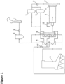
- FIG. 1 shows a first example of an apparatus which does not form part of the present invention.
- the apparatus comprises a drum dryer 1, a discharge housing 2, two cleaning apparatuses 3 which are operated in parallel, two heat-exchangers 4 which are operated in parallel, a grate fired hot gas generator 31, a filter 6 as well as a chimney 7.
- the drying vapors generated by the drying of e.g. wooden chips inside the drum dryer 1 are lead in a drying circuit.
- a drying vapor fan 8 is arranged between the drum dryer 1 and the cleaning apparatuses 3, a burner exhaust fan 9 is arranged between filter 6 and chimney 7 and between heat-exchanger 4 and combustion chamber 5 a regulable partial vapor fan 10 is arranged.
- Dryer 1 may be provided with a slow-down zone 11 and a metering device 12.
- the drum dryer 1 is supplied with bulk goods, as for example with wooden chips and/or wooden fibers.
- the drying gases which are supplied to the drum dryer 1 are heated-up via the heat exchanger 4 and have temperatures in the range of approximately 250° C. up to approximately 600° C.
- the heating of the drying gases in the heat-exchangers 4 is achieved in cross counter flow by means of exhaust gases from the grate fired hot gas generator 31.
- the exhaust gases have temperatures in the range of approximately 750° C. up to approximately 900° C.
- Temperatures of approximately 750° C up to 1050° C are achieved, wherein as fuel for example waste materials from the production of wooden material boards may be used.
- the different fuels may be used alone or in any combination with each other.
- This grate fired hot gas generator 31 is fed with solid combustible material, which e.g. can be waste wooden material etc. This material can be coarser than the material used as fuel for a multi-fuel burner and comprise e.g. wooden chips or even wooden boards. The presence of the grate fired hot gas generator 31 therefore especially allows for the complete thermal recycling of materials which are e.g. generated anywhere during the production processes of chipboards or wooden articles.
- the grate fired hot gas generator 31 is operated with primary gas 34 which can be e.g. fresh ambient air.
- the primary gas can be tempered to elevated temperatures, alternatively the primary air can be used as taken from the surrounding.
- the grate fired hot gas generator 31 is supplied with a partial stream of dryer gases via a separate regulable partial vapor fan 10.
- one slow-down zone 11 may be provided for the drying goods and/or a discharge housing 2 to remove the dried bulk goods.
- the drying gases or the drying vapors, respectively, are driven via the drying vapor fan 8 to one or more cleaning apparatuses 3, preferably cyclone separators.
- a drying vapor fan may be arranged between the cleaning device 3 and the heat exchanger 4.
- fine dust and other particles are separated.
- the separated material may then advantageously be passed to the production or combusted in a hot gas generator such as e.g. the multi-fuel burner 5.
- a hot gas generator such as e.g. the multi-fuel burner 5.
- the drying vapors are heated from approximately 110° C to 130° C up to 250° C to approximately 600° C. This is done in a cross counter flow operation by means of the exhaust gases of the grate fired hot gas generator 31. Inside of the heat-exchangers 4 a part of the vapor is separated and led to the grate fired hot gas generator 31as combustion air and/or cooling air. This part of the vapor is driven by the regulable partial vapor fan 10.
- the exhaust gas of the grate fired hot gas generator 31, which serves to heat-up the drying gases in heat-exchangers 4, is guided - after passing through the heat-exchangers 4 - to a filter 6.
- This is in particular an electrostatic precipitator, preferably a dry type electrostatic precipitator.
- the filter 6 is preferably operated in a suction operation, whereby after the filter 6 a fan 9 for the exhaust gas of the burner is provided. The thus cleaned exhaust gas of the burner is released via chimney 7 into the environment.
- the drying of the wood chips is done in a dedicated vapor circuit.
- a high vapor content can advantageously be achieved and thus a gentle drying can be realized, which has a positive effect on the quality of the drying goods.
- the pollution and thus the wear of the drying circuit can be kept to a minimum.
- the fire protection can be improved due to the indirect heating of the dryer and the dedicated drying circuit.
- the regulation (i.e. control) of the regulable partial vapor fan 10 is done in a preferred embodiment via the pollution level of the exhaust gases of the grate fired hot gas generator 31, as for example by means of the concentration of nitrogen oxides and/or the concentration values of carbon monoxide. Further, the regulable partial vapor fan may be controlled via a maximum inert gas content in the drying circuit or via the oxygen content in the exhaust gas of the grate fired hot gas generator 31.
- the supply of the drum dryer 1 with bulk goods is done while controlling the water content in the dryer by means of the metering device 12, whereby the bulk goods are metered depending on the moisture of different bulk good fractions upon supply to the drum dryer 1.
- different exhaust gases from the manufacturing of the wooden material boards are used as combustion air for the grate fired hot gas generator 31, as for example exhaust gases from the press arrangements, exhaust gases from the sawing arrangements and/or exhaust gases from the boiler.
- the different exhaust gases are preferably pre-heated before they are supplied as combustion air, in particular by means of heat-exchangers. These gases also can be supplied to a grate fired hot gas generator 31.
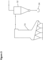
- FIG. 2 shows the inventive apparatus to put the inventive method into practice.
- the same reference numerals refer to the same parts as described for the apparatus shown in FIG. 1 .
- the apparatus according to FIG. 2 comprises a multi-fuel burner 5 with a combustion chamber which is aligned in parallel to the (first) grate fired hot gas generator 31.
- This multi-fuel burner 5 is fed with fossil fuels and under circumstances with additional specific solid combustible material, such as wooden dust.
- the presence of the grate fired hot gas generator 31 therefore allows especially for the complete thermal recycling of materials which are e.g. generated anywhere during the production processes of chipboards or wooden articles.
- the grate fired hot gas generator 31 is operated with primary gas 39 which can be e.g. fresh ambient air 13.
- the primary gas can be tempered to elevated temperatures, in the alternative the primary air can be used as taken from the surrounding.
- the vapor gases branched off the heat exchanger 4 can be added to the grate fired hot gas generator 31 as secondary air 37 or tertiary air 36.
- the multi-fuel burner 5 is supplied with a partial stream 22 of dryer gases via a separate regulable partial vapor fan 40.
- the apparatus according to FIG. 2 furthermore comprises a hot gas cyclone 32 into which both the exhaust gas produced by the grate fired hot gas generator 31 and the multi-fuel burner 5 are fed and cleaned from solid particles which are entrained in the exhaust gas of said hot gas generators, such as e.g. ashes, soot, carbon black etc..
- the collected solids are discharged via lock 33.
- this assembly enables a parallel operation of the multi-fuel burner 5 and the grate fired hot gas generator 31.
- This assembly also allows the alternative operation of the multi-fuel burner 5 or the grate fired hot gas generator 31.
- the gases cleaned by the hot gas cyclone 32 are subsequently used to heat the vapor gases for drying the wooden chips and/or fibers inside the drum dryer 1 by indirect heat exchanging inside the heat exchangers 4.
- the primary air 39 fed to the grate fired hot gas generator 31 preferably can be preheated by means of a heat exchanger 19, which is aligned downstream of the filter 6.
- the filtered exhaust gases 24 are led through the heat exchanger 19, accordingly fresh ambient air 13 can be preheated before being fed to the hot gas generator 31.
- additional air-streams such as press or saw exhaust gases 16, sanding line exhaust gases 17 and/or exhaust gases from a group production line 27 can be preheated in the heat exchanger 19 and fed to the grate fired hot gas generator 31 as primary air.
- the aforementioned gases 13, 16, 17 and 27 can also be used as secondary air 37 and/or tertiary air 36 and fed to the grate fired hot gas generator above the primary firing zone.
- the secondary and/or tertiary gas streams are to reduce the nitrogen oxide content of the exhaust gases generated by the grate fired hot gas generator 31 and/or are used as cooling air.
- the multi-fuel burner 5 comprises a muffle 21, in which the combustion is taking place.
- the gases 13, 16, 17 and/or 27 can be used as primary air and fed into the muffle 21 as combustion air. Inside the muffle combustion air/fuel mixture is ignited and combusted. The mixing of the primary air and the fuel is not displayed in Fig. 2 .
- This primary air can be propelled by separate primary air fan 18.
- drying vapors, which are branched off at 22 from the heat exchangers 4 can be used as cooling air 38 and fed into the multi-fuel burner 5 via a cooling air fan 40 at an outer nozzle ring 30.
- the multi-fuel burner 5 is also provided with an inner nozzle ring, into which muffle cooling air can be supplied via a muffle cooling air fan 41.
- muffle cooling air e. g. fresh ambient air 25 and/or exhaust gases provided by an additional grate fired hot gas generator 31' can be used.
- the apparatus according to Fig. 2 comprises an additional grate fired hot gas generator 31', which can be provided with the same gas streams as the grate fired hot gas generator 31.
- the grate fired hot gas generator 31' comprises an additional thermal oil boiler house 28, in which heat exchangers for recuperation of the thermal energy of the exhaust gases or generated by the grate fired hot gas generator 31' are provided.
- the exhaust gas stream 20 is divided into two parts. A first part is used as muffle cooling air for the multi-fuel burner and added through the inner nozzle ring by means of the muffle cooling air fan 41. The second part of the exhaust gas stream 20 is directly led to the filter 6 and thermally exploited in the heat exchanger 19.
- a further heat exchanger 29 is aligned, in which e. g. hot water or hot thermal oil can be produced. Accordingly, a further energetic exploitation of the thermal energy still contained in the exhaust gas stream can be provided.
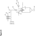
- FIG. 3 shows a detail of the apparatus displayed in FIG. 2 .
- the hot gas cyclone 32 for cleaning of the exhaust gases generated by the grate fired hot gas generator 31 is displayed.
- FIG. 4 shows an additional detail of the apparatus disclosed in FIG. 2 , according to which the exhaust gases of the multi-fuel burner 5 are cleaned by a hot gas cyclone 32.
- the multi-fuel burner 5 can comprise a lock 33 through which solids such as ashes or soot etc. can be discharged.
- Fig. 5 shows a detail of Fig. 2 , in which the heat exchanger 19 is shown in greater detail.
- the exhaust gas stream from 24, which has been cleaned by filter 6 is led through the heat exchanger 19 in order to heat the gas streams numerated with reference numeral 13, 16, 17 and/or 27 as discussed in the foregoing.
- a preheated gas stream 42 leaves the heat exchanger 19 and can be fed to the multi-fuel burner 5 or any of the grate fired hot gas generators 31 and/or 31'.
- Fig. 6 shows details of Fig. 2 , in which the air supply of the multi-fuel burner 5 is displayed in greater detail.
- the multi-fuel burner 5 has three distinct air-supplies, namely the supply of primary air, which can be fed by primary air fan 18.
- the primary air is fed directly into the muffle 21, in which a mixture of the primary air and the fuel is generated and ignited.
- the multi-fuel burner 5 is supplied with cooling air 38 which can be supplied to the multi-fuel burner 5 via outer nozzle rings and by means of regular level cooling air fan 40.
- the cooling air 38 can be e. g. branched off (see reference numerals 22 in Fig. 2 ) from the heat exchanger 4.
- the cooling air can effectively be used to cool the combustion chamber of the multi-fuel burner 5.
- the muffle 21 can be provided with additional muffle cooling air, which can be fed to the multi-fuel burner 5 via inner nozzle rings.
- This muffle cooling air directly is fed inside the muffle 21 and effectively cools the muffle.
- the muffle cooling air can be provided by means of a separate fan 41.
- muffle cooling air e. g. ambient air 25, but also drying vapors, which can be branched off (see reference numeral 22) from the heat exchanger 4 can be used.
- also cleaned exhaust gases which can be stripped off from the exhaust gas stream after the filter 6 can be used.
- pre-heated gases provided as gas stream 42 after the heat exchanger 19 can be used.
- these gases can be pre-heated ambient air 13, press and/or saw exhaust gases 16, sending aligned exhaust gases 17 and/or exhaust gases from a group production line 27.
- muffle cooling air also exhaust gases provided from a separate grate fired hot gas generator 31' can be used.
- Fig. 7 shows another detail of Fig. 2 , in which the complete situation of feeding air and of the gas exhaust generated by the multi-fuel burner 5 is displayed.
- the feeding situation of the multi-fuel burner 5 is identical to the situation displayed in Fig. 6 .
- the hot gas cyclone 32 is visible, which is used for cleaning the exhaust gas generated by the multi-fuel burner 5.
- the fate of the exhaust gas stream after the passing of the hot gas cyclone 32 is shown.
- the exhaust gases are led to the heat exchanger 4 which is used to heat the drying gases (not shown). Afterwards, the exhaust gases pass an electrostatic filter 6 as well as a heat exchanger 19.
- ambient air 25 can be used in addition to the pre-heated gas stream 42 as primary air used in a multi-fuel burner 5.
- Fig. 9 shows an embodiment, in which two grate fired hot gas generators 31 and 31' are supplied with branched off gases (reference numeral 22) from the heat exchanger 4, both as secondary air 37 and tertiary air 36.
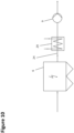
- Fig. 10 shows in detail the electrostatic filter 6, which has also been discussed in the foregoing figures, as well as a heat exchanger 29, which is aligned downstream of the electrostatic filter 6. Said heat exchanger 29 is used for recuperation of thermal energy contained in the exhaust gas stream 24. Furthermore, the exhaust fan 9 is used to operate electrostatic filter as well as the heat exchanger 29.
Landscapes
- Engineering & Computer Science (AREA)
- Mechanical Engineering (AREA)
- General Engineering & Computer Science (AREA)
- Life Sciences & Earth Sciences (AREA)
- Chemical & Material Sciences (AREA)
- Combustion & Propulsion (AREA)
- Sustainable Development (AREA)
- Physics & Mathematics (AREA)
- Thermal Sciences (AREA)
- Microbiology (AREA)
- Drying Of Solid Materials (AREA)
Claims (15)
- Vorrichtung zum Trocknen von Schüttgut, insbesondere von Holzfasern und/oder Holzhackschnitzeln, umfassend:mindestens einen Trockner (1), insbesondere einen Trommeltrockner,mindestens einen Heißgaserzeuger (31, 31', 5) undmindestens einen Wärmetauscher (4), der zur indirekten Erwärmung eines Dampfgasgemisches zur Trocknung des Schüttgutes im Trockner (1) vorgesehen ist, wobei der mindestens eine Wärmetauscher durch Abgase erwärmt wird, die von dem mindestens einen Heißgaserzeuger (31, 31', 5) erzeugt werden,mindestens eine Zweigleitung stromaufwärts, stromabwärts und/oder innerhalb des mindestens einen Wärmetauschers (4) zu dem mindestens einen Heißgaserzeuger (31, 31', 5) zur Abzweigung eines Teilstroms des Dampfgasgemisches, undmindestens eine Leitung für den restlichen Teilstrom zum Trockner (1),dadurch gekennzeichnet, dassder mindestens eine Heißgaserzeuger (31, 31', 5) mindestens einen feststoffbefeuerten Heißgaserzeuger (31, 31') und einen Mehrstoffbrenner (5) zusätzlich zu dem mindestens einen feststoffbefeuerten Heißgaserzeuger (31, 31') umfasst,wobei der Mehrstoffbrenner (5) die Verbrennung von fossilen Brennstoffen oder staubähnlichen Feststoffen ermöglicht, wobei der mindestens eine feststoffbefeuerte Heißgaserzeuger (31, 31') die Verbrennung von brennbarem organischem Material in irgendeiner Form ermöglicht und in der Lage ist, Feststoffe, die im Mehrstoffbrenner (5) nicht verbrannt werden können, zu verbrennen, ohne dass die Zufuhr von fossilen Brennstoffen erforderlich ist,wobei der mindestens eine feststoffbefeuerte Heißgaserzeuger (31, 31') und der Mehrstoffbrenner (5) so eingerichtet sind, dass der mindestens eine feststoffbefeuerte Heißgaserzeuger (31, 31') gleichzeitig oder alternativ zum Mehrstoffbrenner (5) betrieben werden kann.
- Vorrichtung nach Anspruch 1, dadurch gekennzeichnet, dass der mindestens eine feststoffbefeuerte Heißgaserzeuger (31, 31') ein rostbefeuerter Heißgaserzeuger, ein Heißgaserzeuger mit Wirbelschichtfeuerung und/oder ein stokerbefeuerter Heißgaserzeuger ist.
- Vorrichtung nach einem der vorhergehenden Ansprüche, dadurch gekennzeichnet, dassder mindestens eine Mehrstoffbrenner (5) und der mindestens eine feststoffbefeuerte Heißgaserzeuger (31, 31') unabhängig oder parallel sind, der mindestens eine Mehrstoffbrenner (5) eine Brennkammer mit einer Muffel (21), in der ein Brennstoff/Verbrennungsluft-Gemisch gezündet und verbrannt wird, und eine Brennkammerdecke umfasst, wobei die Brennkammerdecke umfasst:- mindestens einen Einlass (18) für Verbrennungsluft in die Muffel,- einen äußeren Düsenring (40), der einen Einlass für ein Kühlgas bildet, das die Muffel (21) umgibt, und- einen inneren Düsenring (41), der einen Einlass für ein Kühlgas im Inneren der Muffel (21) bildet und eine laminare Strömung des Kühlgases entlang der Muffel erzeugt,wobei der innere (41) und der äußere Düsenring (40) getrennt steuerbar sind und der innere Düsenring (41) mit Gas, das von dem mindestens einen feststoffbefeuerten Heißgaserzeuger (31, 31') abgegeben wird, mit Umgebungsluft (13, 25) und/oder mit Gasen aus externen Produktionsprozessen (16, 17, 27) gespeist wird, wobei vorzugsweiseder innere (41) und/oder äußere Düsenring (40) einen Eintrittswinkel von etwa 0 Grad bis etwa 60 Grad, vorzugsweise zwischen 10 und 60 Grad, aufweist.
- Vorrichtung nach einem der vorhergehenden Ansprüche, dadurch gekennzeichnet, dassmindestens ein Heißgaszyklon (32) zwischen dem mindestens einen Heißgasgenerator (31, 31', 5) und dem mindestens einen Wärmetauscher (4) vorgesehen ist, so dass die von dem mindestens einen Heißgasgenerator (31, 31', 5) erzeugten Abgase durch den mindestens einen Heißgaszyklon (32) geleitet werden,mindestens einen Filter (6) zur Reinigung der von dem mindestens einen Heißgaserzeuger (31, 31', 5) erzeugten Abgase vorgesehen ist, insbesondere ein elektrostatischer Abscheider, vorzugsweise ein elektrostatischer Abscheider vom Trockentyp; und stromabwärts des mindestens einen Filters (6) mindestens ein Wärmetauscher (19) vorgesehen ist, der als Einspeisungsluft (18, 36, 37, 39) für den mindestens einen Heißgaserzeuger (31, 31', 5) genutzte Gase (13, 16, 17, 27) indirekt erwärmt, wobei der mindestens eine Wärmetauscher (19) durch die Abgase erwärmt wird, und/oderein Heißgaserzeuger (31, 31', 5) Abgaslüfter (9) stromabwärts des Filters (6) angeordnet ist.
- Vorrichtung nach einem der vorhergehenden Ansprüche, dadurch gekennzeichnet, dass der mindestens eine Heißgaserzeuger (31, 31', 5)mit Gasen gespeist wird, die aus externen Produktionsprozessen (16, 17, 27) stammen und/oderüber die Zweigleitung (22) mit einem Teilstrom des Dampfgasgemisches als Primär- (39), Sekundär- (37) und/oder Tertiärgas (36) versorgt wird.
- Vorrichtung nach einem der vorhergehenden Ansprüche, dadurch gekennzeichnet, dassmindestens ein Wärmetauscher (29) vorgesehen ist, der eine Flüssigkeit indirekt erwärmt, wobei der mindestens eine Wärmetauscher durch die Abgase erwärmt wird, der mindestens eine Wärmetauscher (29) vorzugsweise stromabwärts des mindestens einen Filters (6) angeordnet ist und/oderin der Zweigleitung (22) zu dem mindestens einen Heißgaserzeuger (31, 31', 5) mindestens ein regelbarer Teildampflüfter (36, 37, 39, 40) vorgesehen ist, der vorzugsweise regelbar ist durch mindestens eines voneinem Verschmutzungsgrad in dem von dem mindestens einen Heißgaserzeuger (31, 31', 5) erzeugten Abgas, insbesondere durch einen Stickoxidgehalt und/oder Kohlenmonoxidgehalt in diesem Abgas,einem Sauerstoffgehalt in dem von dem mindestens einen Heißgaserzeuger (31, 31', 5) erzeugten Abgas, und/odereinem maximalen Inertgasgehalt im Dampfgasgemisch zur Trocknung des Schüttgutes im Trockner (1).
- Vorrichtung nach einem der vorhergehenden Ansprüche, dadurch gekennzeichnet, dasszur Reinigung des aus dem mindestens einen Trockner (1) abgegebenen Dampfgasgemisches eine Reinigungsanordnung (3) vorgesehen ist, insbesondere mindestens ein Zyklon, vorzugsweise mindestens eine Zyklonbatterie, und/oderstromabwärts des Trockners (1) mindestens ein Trocknungsdampflüfter (8) vorgesehen ist und/oderzur Regulierung des Wassergehalts im Trockner (1) ist eine Dosiereinrichtung (12) vorgesehen.
- Anordnung zur Herstellung von Holzwerkstoffplatten mit mindestens einer Zerkleinerungseinrichtung, mindestens einer Verpresseinrichtung und mindestens einer Vorrichtung zum Trocknen von Schüttgut nach einem der vorhergehenden Ansprüche.
- Verfahren zur kontinuierlichen Trocknung von Schüttgut, insbesondere Holzfasern und/oder Holzhackschnitzeln, in einem Trockner (1), insbesondere Trommeltrockner, der mit Schüttgut beschickt wird, und der in einem Trocknungskreislauf von einem Dampfgasgemisch durchströmt wird, wobei das Dampfgasgemisch über mindestens einen Wärmetauscher (4) durch Abgas, das von mindestens einem Heißgaserzeuger (31, 31', 5) erzeugt wird, indirekt erwärmt wird, und wobei das Dampfgasgemisch in dem mindestens einen Wärmetauscher (4) geführt und erwärmt wird, und wobei stromaufwärts, stromabwärts und/oder innerhalb des mindestens einen Wärmetauschers (4) zumindest ein Teilstrom des Dampfgasgemisches abgezweigt (22) wird, um in den Heißgaserzeuger (31, 31', 5) geleitet zu werden,
dadurch gekennzeichnet, dassder mindestens eine Heißgaserzeuger (31, 31', 5) mindestens einen feststoffbefeuerten Heißgaserzeuger (31, 31'), welcher mit Biomasse, insbesondere Holzbiomasse, befeuert wird, und einen Mehrstoffbrenner (5) zusätzlich zu dem mindestens einen feststoffbefeuerten Heißgaserzeuger (31, 31') umfasst,wobei der Mehrstoffbrenner (5) die Verbrennung von fossilen Brennstoffen oder staubähnlichen Feststoffen ermöglicht, wobei der mindestens eine feststoffbefeuerte Heißgaserzeuger (31, 31') die Verbrennung von brennbarem organischem Material in irgendeiner Form ermöglicht und in der Lage ist, Feststoffe, die im Mehrstoffbrenner (5) nicht verbrannt werden können, zu verbrennen, ohne dass die Zufuhr von fossilen Brennstoffen erforderlich ist,wobei der mindestens eine feststoffbefeuerte Heißgaserzeuger (31, 31') und der Mehrstoffbrenner (5) so eingerichtet sind, dass der mindestens eine feststoffbefeuerte Heißgaserzeuger (31, 31') gleichzeitig oder alternativ zum Mehrstoffbrenner (5) betrieben werden kann. - Verfahren nach Anspruch 9, dadurch gekennzeichnet, dass der mindestens eine feststoffbefeuerte Heißgaserzeuger ein rostbefeuerter Heißgaserzeuger, ein Heißgaserzeuger mit Wirbelschichtfeuerung und/oder ein stokerbefeuerter Heißgaserzeuger ist.
- Verfahren nach einem der Ansprüche 9 bis 10, dadurch gekennzeichnet, dass der mindestens eine Mehrstoffbrenner (5) und der mindestens eine feststoffbefeuerte Heißgaserzeuger (31, 31') unabhängig oder parallel sind, der mindestens eine Mehrstoffbrenner (5) eine Brennkammer mit einer Muffel (21), in der ein Brennstoff/Verbrennungsluft-Gemisch gezündet und verbrannt wird, und eine Brennkammerdecke umfasst, wobei die Brennkammerdecke umfasst:mindestens einen Einlass (18) für Verbrennungsluft in die Muffel,einen äußeren Düsenring (40), der einen Einlass für ein Kühlgas bildet, das die Muffel umgibt, undeinen inneren Düsenring (41), der einen Einlass für ein Kühlgas im Inneren der Muffel (21) bildet und eine laminare Strömung des Kühlgases entlang der Muffel erzeugt,wobei der innere (41) und der äußere Düsenring (40) getrennt gesteuert werden, und der innere Düsenring (41) mit Gas, das von dem mindestens einen feststoffbefeuerten Heißgaserzeuger (31, 31') abgeführt wird, mit Umgebungsluft (13, 25) und/oder mit Gasen, die aus externen Produktionsprozessen (16, 17, 27) stammen, gespeist wird, wobei vorzugsweiseder innere (41) und/oder der äußere Düsenring (40) einen Eintrittswinkel zwischen etwa 0 und etwa 60 Grad, vorzugsweise zwischen 10 und 60 Grad, aufweist (aufweisen), wobei dieser Winkel vorzugsweise in Abhängigkeit von dem genutzten Kraftstoff einstellbar ist.
- Verfahren nach einem der Ansprüche 9 bis 11, dadurch gekennzeichnet, dass Abgase, welche von mindesten einem Heißgaserzeuger (31, 31', 5) erzeugt werdendurch mindestens einen Heißgaszyklon (32) geleitet werden, der zwischen dem mindestens einen Heißgaserzeuger (31, 31', 5) und dem mindestens einen Wärmetauscher (4) vorgesehen ist und/oderdurch mindestens einen Filter (6), insbesondere einen elektrostatischen Abscheider, vorzugsweise einen elektrostatischen Abscheider vom Trockentyp, gereinigt werden; und stromabwärts des mindestens einen Filters (6) die von dem mindestens einen Heißgaserzeuger (31, 31', 5) erzeugten Abgase zur indirekten Erwärmung von als Einspeisungsluft (18, 36, 37, 39) für den mindestens einen Heißgaserzeuger (31, 31', 5) genutzten Gasen (13, 16, 17, 27) mittels mindestens eines Wärmetauschers (19) genutzt werden, wobei vorzugsweiseder Filter (6) im Ansaugmodus betrieben wird, wobei vorzugsweise mindestens ein Heißgaserzeuger (31, 31', 5) Abgaslüfter (9) stromabwärts des Filter (6) angeordnet ist.
- Verfahren nach einem der Ansprüche 9 bis 12, dadurch gekennzeichnet, dasszumindest ein Heißgaserzeuger (31, 31', 5) mit Gasen gespeist wird, die aus externen Produktionsprozessen (16, 17, 27) stammen,mindestens ein feststoffbefeuerter Heißgaserzeuger (31, 31') über die Zweigleitung (22) mit einem Teilstrom des Dampfgasgemisches als Primär- (39), Sekundär- (37) und/oder Tertiärgas (36) versorgt wird,eine Flüssigkeit durch die Abgase mittels mindestens eines Wärmetauschers (29) indirekt erwärmt wird, wobei der mindestens eine Wärmetauscher (29) vorzugsweise stromabwärts des mindestens einen Filters (6) angeordnet ist und/oderder Teilstrom zu dem mindestens einen Heißgaserzeuger (31, 31', 5) mittels mindestens eines regelbaren Teildampflüfters (10, 36, 37, 39, 40) angetrieben wird, wobei der Teildampflüfter (10, 36, 37, 39, 40) vorzugsweise geregelt wird über mindestens eines voneinem Verschmutzungsgrad der Abgase, die von dem mindestens einen Heißgaserzeuger (31, 31', 5) erzeugt werden, insbesondere durch Stickoxide und/oder Kohlenmonoxide in den Abgasen, und/odereinem Sauerstoffgehalt in dem von dem mindestens einen Heißgaserzeuger (31, 31', 5) erzeugten Abgas, und/odereinem maximalen Inertgasgehalt im Dampfgasgemisch innerhalb des Trocknungskreislaufs.
- Verfahren nach einem der Ansprüche 9 bis 13, dadurch gekennzeichnet, dasszumindest teilweise Feststoffe als Brennstoff für den mindestens einen Heißgaserzeuger (31, 31', 5) genutzt werden, insbesondere Biomasse, wobei vorzugsweise Abfallprodukte aus der Herstellung der Holzwerkstoffplatten genutzt werden,das Dampfgasgemisch nach Durchlaufen des Trockners (1) gereinigt wird, wobei vorzugsweise als Reinigungseinrichtung (3) mindestens ein Zyklon, insbesondere mindestens eine Zyklonbatterie, eingesetzt wird,das Dampfgasgemisch hinter dem Trockner (1) durch zumindest einen Trocknungsdampflüfter (8) betrieben wird und/oderder Wassergehalt im Trockner (1) geregelt wird, wobei vorzugsweise das Schüttgut in Abhängigkeit von der Feuchtigkeit verschiedener Schüttgutfraktionen bei der Beschickung des Trockners (1) dosiert wird.
- Verfahren zur Herstellung von Holzwerkstoffplatten, wobei Scheitholz entrindet und in einer Zerkleinerungsvorrichtung zu Holzhackschnitzeln und/oder Fasern verarbeitet wird, wobei die Holzhackschnitzel und/oder Fasern in einer Trocknungsvorrichtung getrocknet werden, wobei die getrockneten Holzhackschnitzel und/oder Fasern in einer Verpressanordnung zu Platten verarbeitet werden, gegebenenfalls unter Zugabe von Bindemitteln und/oder weiteren Additiven, und vorzugsweise zugeschnitten werden, dadurch gekennzeichnet, dass die Trocknung der Holzhackschnitzel und/oder Fasern in einer Vorrichtung nach einem der Ansprüche 1 bis 8 durchgeführt wird und/oder zur Trocknung der Holzhackschnitzel und/oder Fasern ein Verfahren nach einem der Ansprüche 9 bis 14 durchgeführt wird.
Priority Applications (4)
| Application Number | Priority Date | Filing Date | Title |
|---|---|---|---|
| HRP20250101TT HRP20250101T1 (hr) | 2017-03-03 | 2017-03-03 | Uređaj i postupak za trajno sušenje rasute robe, posebno drvne sječke i/ili drvnih vlakana, koji sadrže generator na kruti vrući plin |
| RS20250097A RS66448B1 (sr) | 2017-03-03 | 2017-03-03 | Uređaj i postupak za kontinuirano sušenje rasutog materijala, određenije drvne sečke i/ili drvnih vlakana, koji obuhvata generator toplog gasa na čvrsto gorivo |
| PL17708524.8T PL3589891T3 (pl) | 2017-03-03 | 2017-03-03 | Urządzenie do i sposób suszenia ciągłego materiałów masowych, w szczególności wiórów drzewnych i/albo włókien drzewnych, zawierające generator gorącego gazu opalany paliwem stałym |
| HUE17708524A HUE070573T2 (hu) | 2017-03-03 | 2017-03-03 | Szilárd tüzelésû forrógáz-generátort magában foglaló berendezés és eljárás ömlesztett áru, különösen faapríték és/vagy farostok folytonos szárítására |
Applications Claiming Priority (1)
| Application Number | Priority Date | Filing Date | Title |
|---|---|---|---|
| PCT/EP2017/055073 WO2018157948A1 (en) | 2017-03-03 | 2017-03-03 | Apparatus and method for continuously drying bulk goods, in particular wood chips and/or wood fibers comprising a solid fired hot gas generator |
Publications (3)
| Publication Number | Publication Date |
|---|---|
| EP3589891A1 EP3589891A1 (de) | 2020-01-08 |
| EP3589891C0 EP3589891C0 (de) | 2024-11-20 |
| EP3589891B1 true EP3589891B1 (de) | 2024-11-20 |
Family
ID=58213106
Family Applications (1)
| Application Number | Title | Priority Date | Filing Date |
|---|---|---|---|
| EP17708524.8A Active EP3589891B1 (de) | 2017-03-03 | 2017-03-03 | Vorrichtung und verfahren zum kontinuierlichen trocknen von schüttgut, insbesondere holzspänen und/oder holzfasern, mit einem festen befeuerten heissgasgenerator |
Country Status (11)
| Country | Link |
|---|---|
| US (1) | US11499778B2 (de) |
| EP (1) | EP3589891B1 (de) |
| CN (1) | CN110382959A (de) |
| EA (1) | EA039823B1 (de) |
| ES (1) | ES3008104T3 (de) |
| HR (1) | HRP20250101T1 (de) |
| HU (1) | HUE070573T2 (de) |
| PL (1) | PL3589891T3 (de) |
| RS (1) | RS66448B1 (de) |
| UA (1) | UA129534C2 (de) |
| WO (1) | WO2018157948A1 (de) |
Families Citing this family (7)
| Publication number | Priority date | Publication date | Assignee | Title |
|---|---|---|---|---|
| HRP20250630T1 (hr) | 2017-03-03 | 2025-07-18 | Kronoplus Limited | Aparatura i postupak za kontinurano sušenje rasutih materijala, naročito drvene sječke i drvenih vlakana , koji obuhvaća višegorivni plamenik sa sustavom hlađenja s prigušivačem |
| US11543124B2 (en) | 2017-03-03 | 2023-01-03 | Kronoplus Limited | Apparatus and method for continuously drying bulk goods, in particular wood chips and/or wood fibers comprising a hot gas cyclone |
| UA126522C2 (uk) | 2017-03-03 | 2022-10-26 | Даґлас Текнікал Лімітед | Установка, яка містить теплообмінник, та спосіб для безперервного сушіння насипних матеріалів, зокрема деревної стружки та/або деревних волокон |
| CA3063517C (en) | 2017-06-06 | 2023-08-01 | Douglas Technical Limited | Apparatus and method for continuously drying bulk goods |
| US11221180B2 (en) * | 2019-04-02 | 2022-01-11 | Innovative Environmental Companies, Inc. | Systems and methods related to staged drying of temperature sensitive materials |
| AT525741B1 (de) * | 2022-04-20 | 2023-07-15 | Iaf Process Eng Gmbh | Verfahren und system zur abwärmerückgewinnung |
| KR102869510B1 (ko) * | 2023-10-16 | 2025-10-14 | 환경에너지솔루션 주식회사 | 연소 가스를 이용한 에너지 회수 시스템 |
Citations (10)
| Publication number | Priority date | Publication date | Assignee | Title |
|---|---|---|---|---|
| EP0334570A2 (de) | 1988-03-22 | 1989-09-27 | Keating Environmental Service, Inc. | Verfahren und Vorrichtung zur Abtrennung von flüchtigen organischen Verbindungen aus festen Stoffen |
| EP0459603A1 (de) | 1990-06-01 | 1991-12-04 | Körting Hannover Ag | Verfahren und Anlage zur kontinuierlichen Trocknung von Holzspänen, Holzfasern oder anderen Schüttgütern |
| EP1830038A1 (de) | 2006-03-01 | 2007-09-05 | Francesco Fuduli | Verfahren zur Kraft- und Wärmeerzeugung sowie Kraft- und Heizwerk |
| DE102006020117A1 (de) | 2006-05-02 | 2007-11-08 | Steag Saar Energie Ag | Dampferzeugungsanlage |
| EP1916478A2 (de) | 2006-10-24 | 2008-04-30 | Fritz Egger GmbH & Co. | Heißgasbetriebene Trocknungsvorrichtung |
| US20080271335A1 (en) | 2007-05-03 | 2008-11-06 | Archer-Daniele-Midland Company | System for using heat to process an agricultural product, a fluidized bed combustor system, and methods of employing the same |
| WO2009087108A1 (de) | 2008-01-10 | 2009-07-16 | Kronospan Cr, Spol. S.R.O. | Verfahren zur kontinuierlichen trocknung von schüttgut, insbesondere von holzfasern und/oder holzspänen |
| EP2202474A1 (de) | 2008-12-23 | 2010-06-30 | Kronotec Ag | Holzzerkleinerungsprodukt-Trocknungsanlage |
| WO2010102736A1 (de) | 2009-03-10 | 2010-09-16 | Kronotec Ag | Holzspantrocknungsanlage zum trocknen von holzspänen und zugehöriges verfahren zum trocknen von holzspänen |
| WO2015140350A1 (de) | 2014-03-21 | 2015-09-24 | Krones Ag | Vorrichtung und verfahren zum betreiben einer gasturbine mit direkter beschickung dieser gasturbine |
Family Cites Families (38)
| Publication number | Priority date | Publication date | Assignee | Title |
|---|---|---|---|---|
| US653819A (en) | 1899-11-09 | 1900-07-17 | Louis Hubert Willem Regout | Muffle furnace or oven. |
| US2753925A (en) | 1951-07-05 | 1956-07-10 | Sinclair Refining Co | Carbon monoxide burner |
| DE2734973C2 (de) | 1977-08-03 | 1982-12-16 | Kernforschungsanlage Jülich GmbH, 5170 Jülich | Verfahren und Verbrennungsofen zum Verbrennen von Abfällen |
| US4276835A (en) | 1979-10-04 | 1981-07-07 | Von Roll Ag | method for processing sewage sludge |
| DE3729971A1 (de) | 1987-09-08 | 1989-03-16 | Wuenning Joachim | Heissgaserzeugungseinrichtung mit thermischer nachverbrennung |
| SE461962B (sv) | 1987-12-16 | 1990-04-23 | Sunds Defibrator Ind Ab | Saett och anordning foer framstaellning av fiberboardskivor |
| CH676500A5 (de) * | 1990-05-18 | 1991-01-31 | Werner Kunz | |
| US5248387A (en) | 1991-02-15 | 1993-09-28 | Niro A/S | Process for producing concentrated aqueous slurries and spray dried particulate products |
| ATE161622T1 (de) | 1994-11-24 | 1998-01-15 | Kunz Drytec Ag W | Verfahren zum trocknen einer substanz, insbesondere von holzspänen |
| SE509089C2 (sv) | 1997-04-30 | 1998-12-07 | Sunds Defibrator Ind Ab | Förfarande vid framställning av skivor från lignocellulosahaltigt material |
| JPH11148626A (ja) * | 1997-11-20 | 1999-06-02 | Takuma Co Ltd | 木屑焚き燃焼炉及び炉への木屑類供給方法 |
| AT406901B (de) | 1998-04-17 | 2000-10-25 | Andritz Patentverwaltung | Verfahren und vorrichtung zur verbrennung von partikelförmigen feststoffen |
| SE515426C2 (sv) | 1999-12-03 | 2001-08-06 | Valmet Fibertech Ab | Sätt för torkning av lignocellulosahaltigt fibermaterial |
| WO2003013809A1 (de) | 2001-08-01 | 2003-02-20 | Kronospan Technical Company Ltd. | Umweltfreundlich hergestellte platte aus einem holzwerkstoff |
| DE20112599U1 (de) | 2001-08-01 | 2002-12-19 | Kronospan Technical Co. Ltd., Nikosia | MDF-Platte nebst Herstellung |
| CA2562372C (en) | 2004-04-09 | 2012-04-03 | Turbosonic Inc. | Pollution control in wood products dryer |
| US6974494B1 (en) | 2004-10-25 | 2005-12-13 | Karim Zahedi | Apparatus and method using an electrified filter bed for removal of pollutants from a flue gas stream |
| ATE440251T1 (de) | 2005-09-27 | 2009-09-15 | Dall Energy Holding Aps | Verfahren und system zur erwärmung von wasser auf grundlage heisser gase |
| US20070251120A1 (en) | 2006-04-20 | 2007-11-01 | Connell Larry V | Method of drying and pulverizing organic materials |
| US7531769B2 (en) | 2006-06-13 | 2009-05-12 | Guy Smith | Carbon fiber composite muffle |
| US8161661B2 (en) | 2008-02-26 | 2012-04-24 | Active Land International Corporation | Continuous drying apparatus and method |
| CN201233166Y (zh) | 2008-06-27 | 2009-05-06 | 成都市新都化工股份有限公司 | 沸腾热风炉 |
| JP5340716B2 (ja) * | 2008-12-12 | 2013-11-13 | 川崎重工業株式会社 | 倒立形低noxボイラ |
| GB0902629D0 (en) | 2009-02-17 | 2009-04-01 | Dickinson Legg Ltd | Tabacco drying apparatus |
| DE102010014479B4 (de) * | 2010-04-09 | 2012-01-12 | Fritz Egger Gmbh & Co. Og | Vorrichtung und Verfahren zur Heißgaserzeugung mit integrierter Erhitzung eines Wärmeträgermediums |
| WO2012064545A2 (en) * | 2010-11-10 | 2012-05-18 | Praxair Technology, Inc. | Oxygen enhanced combustion of biomass |
| US9200834B1 (en) | 2013-03-14 | 2015-12-01 | Kiln Drying Systems & Components, Inc. | Uninterrupted alternating air circulation for continuous drying lumber kilns |
| CA2909407A1 (en) | 2013-04-09 | 2014-10-16 | Diacarbon Technologies Inc. | Torrefaction process |
| CN103471369A (zh) * | 2013-09-05 | 2013-12-25 | 山东天力干燥股份有限公司 | 一种用过热蒸汽携湿的蒸汽回转干燥工艺及褐煤干燥方法 |
| US20150107749A1 (en) | 2013-10-18 | 2015-04-23 | Unilin, Bvba | Process and Device for Gluing Dried Fibers Designated for the Production of Fiberboards |
| CN104154548B (zh) * | 2014-07-31 | 2016-06-22 | 佘洪舟 | 一种燃气锅炉尾气热能回收及氮氧化物净化的工艺 |
| CN204268851U (zh) | 2014-10-17 | 2015-04-15 | 衡水捷信金属结构有限公司 | 闪蒸干燥机 |
| US9682363B2 (en) | 2015-11-10 | 2017-06-20 | Preferred Utilities Manufacturing Corporation | Method for production of activated carbon |
| US10415825B2 (en) * | 2016-06-07 | 2019-09-17 | The Babcock & Wilcox Company | Methods of generating energy from cellulosic biofuel waste |
| UA126522C2 (uk) | 2017-03-03 | 2022-10-26 | Даґлас Текнікал Лімітед | Установка, яка містить теплообмінник, та спосіб для безперервного сушіння насипних матеріалів, зокрема деревної стружки та/або деревних волокон |
| US11543124B2 (en) | 2017-03-03 | 2023-01-03 | Kronoplus Limited | Apparatus and method for continuously drying bulk goods, in particular wood chips and/or wood fibers comprising a hot gas cyclone |
| HRP20250630T1 (hr) | 2017-03-03 | 2025-07-18 | Kronoplus Limited | Aparatura i postupak za kontinurano sušenje rasutih materijala, naročito drvene sječke i drvenih vlakana , koji obuhvaća višegorivni plamenik sa sustavom hlađenja s prigušivačem |
| CA3063517C (en) * | 2017-06-06 | 2023-08-01 | Douglas Technical Limited | Apparatus and method for continuously drying bulk goods |
-
2017
- 2017-03-03 CN CN201780087916.7A patent/CN110382959A/zh active Pending
- 2017-03-03 WO PCT/EP2017/055073 patent/WO2018157948A1/en not_active Ceased
- 2017-03-03 RS RS20250097A patent/RS66448B1/sr unknown
- 2017-03-03 HR HRP20250101TT patent/HRP20250101T1/hr unknown
- 2017-03-03 US US16/489,788 patent/US11499778B2/en active Active
- 2017-03-03 UA UAA201909524A patent/UA129534C2/uk unknown
- 2017-03-03 HU HUE17708524A patent/HUE070573T2/hu unknown
- 2017-03-03 PL PL17708524.8T patent/PL3589891T3/pl unknown
- 2017-03-03 EP EP17708524.8A patent/EP3589891B1/de active Active
- 2017-03-03 ES ES17708524T patent/ES3008104T3/es active Active
- 2017-03-03 EA EA201991754A patent/EA039823B1/ru unknown
Patent Citations (11)
| Publication number | Priority date | Publication date | Assignee | Title |
|---|---|---|---|---|
| EP0334570A2 (de) | 1988-03-22 | 1989-09-27 | Keating Environmental Service, Inc. | Verfahren und Vorrichtung zur Abtrennung von flüchtigen organischen Verbindungen aus festen Stoffen |
| EP0459603A1 (de) | 1990-06-01 | 1991-12-04 | Körting Hannover Ag | Verfahren und Anlage zur kontinuierlichen Trocknung von Holzspänen, Holzfasern oder anderen Schüttgütern |
| EP1830038A1 (de) | 2006-03-01 | 2007-09-05 | Francesco Fuduli | Verfahren zur Kraft- und Wärmeerzeugung sowie Kraft- und Heizwerk |
| DE102006020117A1 (de) | 2006-05-02 | 2007-11-08 | Steag Saar Energie Ag | Dampferzeugungsanlage |
| EP1916478A2 (de) | 2006-10-24 | 2008-04-30 | Fritz Egger GmbH & Co. | Heißgasbetriebene Trocknungsvorrichtung |
| US20080271335A1 (en) | 2007-05-03 | 2008-11-06 | Archer-Daniele-Midland Company | System for using heat to process an agricultural product, a fluidized bed combustor system, and methods of employing the same |
| WO2009087108A1 (de) | 2008-01-10 | 2009-07-16 | Kronospan Cr, Spol. S.R.O. | Verfahren zur kontinuierlichen trocknung von schüttgut, insbesondere von holzfasern und/oder holzspänen |
| US20170051972A1 (en) | 2008-01-10 | 2017-02-23 | Douglas Technical Limited | Method for continuously drying bulk goods, in particular wood fibers and/or wood chips |
| EP2202474A1 (de) | 2008-12-23 | 2010-06-30 | Kronotec Ag | Holzzerkleinerungsprodukt-Trocknungsanlage |
| WO2010102736A1 (de) | 2009-03-10 | 2010-09-16 | Kronotec Ag | Holzspantrocknungsanlage zum trocknen von holzspänen und zugehöriges verfahren zum trocknen von holzspänen |
| WO2015140350A1 (de) | 2014-03-21 | 2015-09-24 | Krones Ag | Vorrichtung und verfahren zum betreiben einer gasturbine mit direkter beschickung dieser gasturbine |
Non-Patent Citations (1)
| Title |
|---|
| SVOBODA KAREL, MARTINEC JIŘÍ, POHOŘELÝ MICHAEL, BAXTER DAVID: "Integration of biomass drying with combustion/gasification technologies and minimization of emissions of organic compounds", CHEMICAL PAPERS, SP VERSITA, HEIDELBERG, vol. 63, no. 1, 30 October 2008 (2008-10-30), Heidelberg , XP093306794, ISSN: 1336-9075, DOI: 10.2478/s11696-008-0080-5 |
Also Published As
| Publication number | Publication date |
|---|---|
| US11499778B2 (en) | 2022-11-15 |
| EP3589891C0 (de) | 2024-11-20 |
| EP3589891A1 (de) | 2020-01-08 |
| EA201991754A1 (ru) | 2020-02-28 |
| ES3008104T3 (en) | 2025-03-21 |
| US20200011600A1 (en) | 2020-01-09 |
| HRP20250101T1 (hr) | 2025-03-28 |
| CA3053982A1 (en) | 2018-09-07 |
| RS66448B1 (sr) | 2025-02-28 |
| UA129534C2 (uk) | 2025-05-28 |
| PL3589891T3 (pl) | 2025-03-03 |
| WO2018157948A1 (en) | 2018-09-07 |
| EA039823B1 (ru) | 2022-03-17 |
| CN110382959A (zh) | 2019-10-25 |
| HUE070573T2 (hu) | 2025-06-28 |
Similar Documents
| Publication | Publication Date | Title |
|---|---|---|
| EP3589893B1 (de) | Vorrichtung und verfahren zum kontinuierlichen trocknen von schüttgut, insbesondere von holzspänen und/oder holzfasern, mit einem heissgaszyklon | |
| EP3589891B1 (de) | Vorrichtung und verfahren zum kontinuierlichen trocknen von schüttgut, insbesondere holzspänen und/oder holzfasern, mit einem festen befeuerten heissgasgenerator | |
| US10690409B2 (en) | Method for continuously drying bulk goods, in particular wood fibers and/or wood chips | |
| EP3589890B1 (de) | Vorrichtung und verfahren zum kontinuierlichen trocknen von schüttgut, insbesondere holzspänen und/oder holzfasern, mit einem wärmetauscher | |
| EP3589892B1 (de) | Vorrichtung und verfahren zum kontinuierlichen trocknen von schüttgut, insbesondere von holzspänen und/oder holzfasern, mit einem mehrstoffbrenner mit einem muffelkühlsystem | |
| CA3063517C (en) | Apparatus and method for continuously drying bulk goods | |
| CA3053982C (en) | Apparatus and method for continuously drying bulk goods, in particular wood chips and/or wood fibers comprising a solid fired hot gas generator | |
| CA3053976C (en) | Apparatus and method for continuously drying bulk goods, in particular wood chips and/or wood fibers comprising a hot gas cyclone | |
| EA041059B1 (ru) | Устройство и способ непрерывной сушки сыпучих продуктов, в частности древесной стружки и/или древесных волокон, включающие циклон для горячего газа |
Legal Events
| Date | Code | Title | Description |
|---|---|---|---|
| REG | Reference to a national code |
Ref country code: HR Ref legal event code: TUEP Ref document number: P20250101T Country of ref document: HR |
|
| STAA | Information on the status of an ep patent application or granted ep patent |
Free format text: STATUS: UNKNOWN |
|
| STAA | Information on the status of an ep patent application or granted ep patent |
Free format text: STATUS: THE INTERNATIONAL PUBLICATION HAS BEEN MADE |
|
| PUAI | Public reference made under article 153(3) epc to a published international application that has entered the european phase |
Free format text: ORIGINAL CODE: 0009012 |
|
| STAA | Information on the status of an ep patent application or granted ep patent |
Free format text: STATUS: REQUEST FOR EXAMINATION WAS MADE |
|
| 17P | Request for examination filed |
Effective date: 20190906 |
|
| AK | Designated contracting states |
Kind code of ref document: A1 Designated state(s): AL AT BE BG CH CY CZ DE DK EE ES FI FR GB GR HR HU IE IS IT LI LT LU LV MC MK MT NL NO PL PT RO RS SE SI SK SM TR |
|
| AX | Request for extension of the european patent |
Extension state: BA ME |
|
| DAV | Request for validation of the european patent (deleted) | ||
| DAX | Request for extension of the european patent (deleted) | ||
| STAA | Information on the status of an ep patent application or granted ep patent |
Free format text: STATUS: EXAMINATION IS IN PROGRESS |
|
| 17Q | First examination report despatched |
Effective date: 20220621 |
|
| RAP1 | Party data changed (applicant data changed or rights of an application transferred) |
Owner name: KRONOPLUS LIMITED |
|
| GRAP | Despatch of communication of intention to grant a patent |
Free format text: ORIGINAL CODE: EPIDOSNIGR1 |
|
| STAA | Information on the status of an ep patent application or granted ep patent |
Free format text: STATUS: GRANT OF PATENT IS INTENDED |
|
| INTG | Intention to grant announced |
Effective date: 20240627 |
|
| GRAS | Grant fee paid |
Free format text: ORIGINAL CODE: EPIDOSNIGR3 |
|
| GRAA | (expected) grant |
Free format text: ORIGINAL CODE: 0009210 |
|
| STAA | Information on the status of an ep patent application or granted ep patent |
Free format text: STATUS: THE PATENT HAS BEEN GRANTED |
|
| AK | Designated contracting states |
Kind code of ref document: B1 Designated state(s): AL AT BE BG CH CY CZ DE DK EE ES FI FR GB GR HR HU IE IS IT LI LT LU LV MC MK MT NL NO PL PT RO RS SE SI SK SM TR |
|
| REG | Reference to a national code |
Ref country code: GB Ref legal event code: FG4D |
|
| REG | Reference to a national code |
Ref country code: CH Ref legal event code: EP |
|
| REG | Reference to a national code |
Ref country code: DE Ref legal event code: R096 Ref document number: 602017086212 Country of ref document: DE |
|
| REG | Reference to a national code |
Ref country code: IE Ref legal event code: FG4D |
|
| U01 | Request for unitary effect filed |
Effective date: 20241218 |
|
| U07 | Unitary effect registered |
Designated state(s): AT BE BG DE DK EE FI FR IT LT LU LV MT NL PT RO SE SI Effective date: 20250103 |
|
| U20 | Renewal fee for the european patent with unitary effect paid |
Year of fee payment: 9 Effective date: 20250109 |
|
| REG | Reference to a national code |
Ref country code: HR Ref legal event code: ODRP Ref document number: P20250101T Country of ref document: HR Payment date: 20250218 Year of fee payment: 9 |
|
| REG | Reference to a national code |
Ref country code: ES Ref legal event code: FG2A Ref document number: 3008104 Country of ref document: ES Kind code of ref document: T3 Effective date: 20250321 |
|
| REG | Reference to a national code |
Ref country code: HR Ref legal event code: T1PR Ref document number: P20250101 Country of ref document: HR |
|
| PG25 | Lapsed in a contracting state [announced via postgrant information from national office to epo] |
Ref country code: IS Free format text: LAPSE BECAUSE OF FAILURE TO SUBMIT A TRANSLATION OF THE DESCRIPTION OR TO PAY THE FEE WITHIN THE PRESCRIBED TIME-LIMIT Effective date: 20250320 |
|
| REG | Reference to a national code |
Ref country code: SK Ref legal event code: T3 Ref document number: E 46030 Country of ref document: SK |
|
| PG25 | Lapsed in a contracting state [announced via postgrant information from national office to epo] |
Ref country code: GR Free format text: LAPSE BECAUSE OF FAILURE TO SUBMIT A TRANSLATION OF THE DESCRIPTION OR TO PAY THE FEE WITHIN THE PRESCRIBED TIME-LIMIT Effective date: 20250221 |
|
| PGFP | Annual fee paid to national office [announced via postgrant information from national office to epo] |
Ref country code: PL Payment date: 20250205 Year of fee payment: 9 Ref country code: CZ Payment date: 20250213 Year of fee payment: 9 |
|
| PGFP | Annual fee paid to national office [announced via postgrant information from national office to epo] |
Ref country code: SK Payment date: 20250224 Year of fee payment: 9 |
|
| REG | Reference to a national code |
Ref country code: HU Ref legal event code: AG4A Ref document number: E070573 Country of ref document: HU |
|
| PG25 | Lapsed in a contracting state [announced via postgrant information from national office to epo] |
Ref country code: SM Free format text: LAPSE BECAUSE OF FAILURE TO SUBMIT A TRANSLATION OF THE DESCRIPTION OR TO PAY THE FEE WITHIN THE PRESCRIBED TIME-LIMIT Effective date: 20241120 |
|
| PGFP | Annual fee paid to national office [announced via postgrant information from national office to epo] |
Ref country code: ES Payment date: 20250404 Year of fee payment: 9 |
|
| PLBI | Opposition filed |
Free format text: ORIGINAL CODE: 0009260 |
|
| PLAX | Notice of opposition and request to file observation + time limit sent |
Free format text: ORIGINAL CODE: EPIDOSNOBS2 |
|
| 26 | Opposition filed |
Opponent name: NUEBOLD, HENRIK Effective date: 20250820 |
|
| PG25 | Lapsed in a contracting state [announced via postgrant information from national office to epo] |
Ref country code: MC Free format text: LAPSE BECAUSE OF FAILURE TO SUBMIT A TRANSLATION OF THE DESCRIPTION OR TO PAY THE FEE WITHIN THE PRESCRIBED TIME-LIMIT Effective date: 20241120 |
|
| REG | Reference to a national code |
Ref country code: CH Ref legal event code: H13 Free format text: ST27 STATUS EVENT CODE: U-0-0-H10-H13 (AS PROVIDED BY THE NATIONAL OFFICE) Effective date: 20251023 |
|
| PLBB | Reply of patent proprietor to notice(s) of opposition received |
Free format text: ORIGINAL CODE: EPIDOSNOBS3 |
|
| PG25 | Lapsed in a contracting state [announced via postgrant information from national office to epo] |
Ref country code: CH Free format text: LAPSE BECAUSE OF NON-PAYMENT OF DUE FEES Effective date: 20250331 |
|
| PG25 | Lapsed in a contracting state [announced via postgrant information from national office to epo] |
Ref country code: IE Free format text: LAPSE BECAUSE OF NON-PAYMENT OF DUE FEES Effective date: 20250303 |
|
| REG | Reference to a national code |
Ref country code: HR Ref legal event code: ODRP Ref document number: P20250101 Country of ref document: HR Payment date: 20260219 Year of fee payment: 10 |
|
| PGFP | Annual fee paid to national office [announced via postgrant information from national office to epo] |
Ref country code: GB Payment date: 20260324 Year of fee payment: 10 |
|
| PGFP | Annual fee paid to national office [announced via postgrant information from national office to epo] |
Ref country code: NO Payment date: 20260323 Year of fee payment: 10 |
|
| PGFP | Annual fee paid to national office [announced via postgrant information from national office to epo] |
Ref country code: HR Payment date: 20260219 Year of fee payment: 10 |
|
| PGFP | Annual fee paid to national office [announced via postgrant information from national office to epo] |
Ref country code: HU Payment date: 20260323 Year of fee payment: 10 |
|
| PGFP | Annual fee paid to national office [announced via postgrant information from national office to epo] |
Ref country code: RS Payment date: 20260219 Year of fee payment: 10 |
|
| PGFP | Annual fee paid to national office [announced via postgrant information from national office to epo] |
Ref country code: TR Payment date: 20260225 Year of fee payment: 10 |