EP3589892B1 - Vorrichtung und verfahren zum kontinuierlichen trocknen von schüttgut, insbesondere von holzspänen und/oder holzfasern, mit einem mehrstoffbrenner mit einem muffelkühlsystem - Google Patents
Vorrichtung und verfahren zum kontinuierlichen trocknen von schüttgut, insbesondere von holzspänen und/oder holzfasern, mit einem mehrstoffbrenner mit einem muffelkühlsystem Download PDFInfo
- Publication number
- EP3589892B1 EP3589892B1 EP17708525.5A EP17708525A EP3589892B1 EP 3589892 B1 EP3589892 B1 EP 3589892B1 EP 17708525 A EP17708525 A EP 17708525A EP 3589892 B1 EP3589892 B1 EP 3589892B1
- Authority
- EP
- European Patent Office
- Prior art keywords
- hot gas
- gas generator
- drying
- heat exchanger
- exhaust gases
- Prior art date
- Legal status (The legal status is an assumption and is not a legal conclusion. Google has not performed a legal analysis and makes no representation as to the accuracy of the status listed.)
- Active
Links
Images


Classifications
-
- F—MECHANICAL ENGINEERING; LIGHTING; HEATING; WEAPONS; BLASTING
- F23—COMBUSTION APPARATUS; COMBUSTION PROCESSES
- F23G—CREMATION FURNACES; CONSUMING WASTE PRODUCTS BY COMBUSTION
- F23G5/00—Incineration of waste; Incinerator constructions; Details, accessories or control therefor
- F23G5/006—General arrangement of incineration plant, e.g. flow sheets
-
- F—MECHANICAL ENGINEERING; LIGHTING; HEATING; WEAPONS; BLASTING
- F23—COMBUSTION APPARATUS; COMBUSTION PROCESSES
- F23G—CREMATION FURNACES; CONSUMING WASTE PRODUCTS BY COMBUSTION
- F23G5/00—Incineration of waste; Incinerator constructions; Details, accessories or control therefor
- F23G5/008—Incineration of waste; Incinerator constructions; Details, accessories or control therefor adapted for burning two or more kinds, e.g. liquid and solid, of waste being fed through separate inlets
-
- F—MECHANICAL ENGINEERING; LIGHTING; HEATING; WEAPONS; BLASTING
- F23—COMBUSTION APPARATUS; COMBUSTION PROCESSES
- F23G—CREMATION FURNACES; CONSUMING WASTE PRODUCTS BY COMBUSTION
- F23G5/00—Incineration of waste; Incinerator constructions; Details, accessories or control therefor
- F23G5/02—Incineration of waste; Incinerator constructions; Details, accessories or control therefor with pretreatment
- F23G5/04—Incineration of waste; Incinerator constructions; Details, accessories or control therefor with pretreatment drying
-
- F—MECHANICAL ENGINEERING; LIGHTING; HEATING; WEAPONS; BLASTING
- F23—COMBUSTION APPARATUS; COMBUSTION PROCESSES
- F23G—CREMATION FURNACES; CONSUMING WASTE PRODUCTS BY COMBUSTION
- F23G5/00—Incineration of waste; Incinerator constructions; Details, accessories or control therefor
- F23G5/44—Details; Accessories
- F23G5/46—Recuperation of heat
-
- F—MECHANICAL ENGINEERING; LIGHTING; HEATING; WEAPONS; BLASTING
- F23—COMBUSTION APPARATUS; COMBUSTION PROCESSES
- F23J—REMOVAL OR TREATMENT OF COMBUSTION PRODUCTS OR COMBUSTION RESIDUES; FLUES
- F23J15/00—Arrangements of devices for treating smoke or fumes
- F23J15/02—Arrangements of devices for treating smoke or fumes of purifiers, e.g. for removing noxious material
- F23J15/022—Arrangements of devices for treating smoke or fumes of purifiers, e.g. for removing noxious material for removing solid particulate material from the gasflow
- F23J15/027—Arrangements of devices for treating smoke or fumes of purifiers, e.g. for removing noxious material for removing solid particulate material from the gasflow using cyclone separators
-
- F—MECHANICAL ENGINEERING; LIGHTING; HEATING; WEAPONS; BLASTING
- F26—DRYING
- F26B—DRYING SOLID MATERIALS OR OBJECTS BY REMOVING LIQUID THEREFROM
- F26B11/00—Machines or apparatus for drying solid materials or objects with movement which is non-progressive
- F26B11/02—Machines or apparatus for drying solid materials or objects with movement which is non-progressive in moving drums or other mainly-closed receptacles
- F26B11/04—Machines or apparatus for drying solid materials or objects with movement which is non-progressive in moving drums or other mainly-closed receptacles rotating about a horizontal or slightly-inclined axis
-
- F—MECHANICAL ENGINEERING; LIGHTING; HEATING; WEAPONS; BLASTING
- F26—DRYING
- F26B—DRYING SOLID MATERIALS OR OBJECTS BY REMOVING LIQUID THEREFROM
- F26B21/00—Arrangements or duct systems, e.g. in combination with pallet boxes, for supplying and controlling air or gases for drying solid materials or objects
- F26B21/02—Circulating air or gases in closed cycles, e.g. wholly within the drying enclosure
-
- F—MECHANICAL ENGINEERING; LIGHTING; HEATING; WEAPONS; BLASTING
- F23—COMBUSTION APPARATUS; COMBUSTION PROCESSES
- F23G—CREMATION FURNACES; CONSUMING WASTE PRODUCTS BY COMBUSTION
- F23G2203/00—Furnace arrangements
- F23G2203/10—Stoker grate furnace
-
- F—MECHANICAL ENGINEERING; LIGHTING; HEATING; WEAPONS; BLASTING
- F23—COMBUSTION APPARATUS; COMBUSTION PROCESSES
- F23G—CREMATION FURNACES; CONSUMING WASTE PRODUCTS BY COMBUSTION
- F23G2209/00—Specific waste
- F23G2209/26—Biowaste
- F23G2209/261—Woodwaste
-
- F—MECHANICAL ENGINEERING; LIGHTING; HEATING; WEAPONS; BLASTING
- F23—COMBUSTION APPARATUS; COMBUSTION PROCESSES
- F23G—CREMATION FURNACES; CONSUMING WASTE PRODUCTS BY COMBUSTION
- F23G2900/00—Special features of, or arrangements for incinerators
- F23G2900/50001—Combination of two or more furnaces
-
- F—MECHANICAL ENGINEERING; LIGHTING; HEATING; WEAPONS; BLASTING
- F26—DRYING
- F26B—DRYING SOLID MATERIALS OR OBJECTS BY REMOVING LIQUID THEREFROM
- F26B2200/00—Drying processes and machines for solid materials characterised by the specific requirements of the drying good
- F26B2200/24—Wood particles, e.g. shavings, cuttings, saw dust
-
- F—MECHANICAL ENGINEERING; LIGHTING; HEATING; WEAPONS; BLASTING
- F26—DRYING
- F26B—DRYING SOLID MATERIALS OR OBJECTS BY REMOVING LIQUID THEREFROM
- F26B23/00—Heating arrangements
- F26B23/02—Heating arrangements using combustion heating
- F26B23/022—Heating arrangements using combustion heating incinerating volatiles in the dryer exhaust gases, the produced hot gases being wholly, partly or not recycled into the drying enclosure
-
- Y—GENERAL TAGGING OF NEW TECHNOLOGICAL DEVELOPMENTS; GENERAL TAGGING OF CROSS-SECTIONAL TECHNOLOGIES SPANNING OVER SEVERAL SECTIONS OF THE IPC; TECHNICAL SUBJECTS COVERED BY FORMER USPC CROSS-REFERENCE ART COLLECTIONS [XRACs] AND DIGESTS
- Y02—TECHNOLOGIES OR APPLICATIONS FOR MITIGATION OR ADAPTATION AGAINST CLIMATE CHANGE
- Y02P—CLIMATE CHANGE MITIGATION TECHNOLOGIES IN THE PRODUCTION OR PROCESSING OF GOODS
- Y02P70/00—Climate change mitigation technologies in the production process for final industrial or consumer products
- Y02P70/10—Greenhouse gas [GHG] capture, material saving, heat recovery or other energy efficient measures, e.g. motor control, characterised by manufacturing processes, e.g. for rolling metal or metal working
Definitions
- the present invention relates to an apparatus and a method for continuously drying bulk goods, in particular wood fibers and/or wood chips, in a dryer, wherein the drying vapors are led to a dryer circuit, in which the drying vapors are indirectly heated via a heat-exchanger and are conducted to the dryer again.
- the manufacturing of boards made from wood materials is based essentially on the pressing of hackled wood pieces, in particular of wood fibers and/or wood chips.
- a chip board consists of small wood chips with different thicknesses, which are pressed together with a binder and under application of high pressure to form boards.
- Wood fiber boards are produced from wooden fiber with or without an additional bonding agent.
- the hackled wood pieces Before being pressed to boards, the hackled wood pieces have to be dried. This is usually done in so called drum dryers, wherein the goods to be dried respectively the bulk goods are moved in a heated, rotating tube. During the drying in addition to water vapor also gaseous wood contents are freed which must not be released to the environment since they are considered as pollutants. The drying vapors are further contaminated with fine particulate matter. For these reasons, the drying vapors have to be cleaned before they can be released to the environment. This is usually achieved by dust removal, filtering and/or a burn-out in the burner of the dryer. To reduce the costs for this treatment of the drying gases and in particular to reduce the additionally necessary energy consumption, different methods and apparatuses are suggested, which enable a more economic process by guiding the drying gases in a circuit and subjecting the same to an indirect heating via a burner.
- the European patent application EP 0 459 603 A1 for example describes a drying of wood fibers in a drum dryer, wherein the drying vapors exiting the dryer are led back in a circuit to the dryer and are heated indirectly through the heating gas produced by the burner until they reach the temperatures necessary for drying the wood chips. A part of the drying vapor is removed from this circuit and guided to the combustion chamber. The exhaust gases from the combustion chamber, which are used to heat-up the drying gases via a heat-exchanger, are cleaned with a filter, before they are released to the environment.
- the European patent application EP 0 457 203 A1 also describes a drying method among others for wood chips, wherein the drying gases are indirectly heated by a heat-exchanger and wherein the heat-exchanger is energized with the exhaust gases of a combustion chamber. A part of the drying vapors is continuously removed from the dryer and fed to a condenser wherein the water content is condensed and wherein the non-condensable gases are led as combustion air into the combustion chamber.
- International Patent Application WO 2009/087108 A1 describes a method and an apparatus for continuously drying bulk goods, in particular wood fibers and/or wood chips in a dryer, which is indirectly heated by a burner exhaust gas, wherein the drying vapors resulting from the dryer are guided and heated up in at least one heat exchanger heated by the burner exhaust gas. At least a part of the dryer vapors is branched off to be conducted into the burner, wherein this partial flow to the burner is driven by means of at least one regularly partial vapor fan.
- US2017051972A1 describes another apparatus and method for drying bulk goods.
- a problem of the known methods is that the nitrous oxide concentration in the exhaust gas produced by the burner is relatively high. This makes it necessary to additionally provide exhaust gas cleaning in order to reduce the nitrous oxide content in the exhaust gas of the burner to tolerable levels thus making the apparatus and the method complex and cost-intensive.
- the invention relates to an apparatus for the drying of bulk goods, in particular of wood fibers and/or wood chips, with a dryer, in particular a drum dryer, through which a vapor gas mixture (drying vapors) is passed in a drying circuit.
- the apparatus further comprises at least one heat-exchanger for the indirect heating-up of the vapor gas mixture and it comprises at least one hot gas generator.
- the at least one hot gas generator creates exhaust gases, which can be used for the indirect heating of the vapor gas mixture via the at least one heat-exchanger.
- At least one branch line to the at least one hot gas generator is provided upstream, downstream and/or within the at least one heat-exchanger for a partial flow of the drying vapors and at least one line is provided for the remaining part of the drying vapors to the dryer.
- the apparatus according to the invention is characterized in that the at least one hot gas generator comprises at least one multi-fuel burner and at least one solid fired hot gas generator which are aligned in parallel, said at least one multi-fuel burner comprises a combustion chamber with a muffle in which a fuel/combustion air mixture is ignited and burned and a combustion chamber ceiling, said combustion chamber ceiling comprising
- a special feature underlying the present invention is that at least said inner and an outer nozzle ring being separately controllable and said inner nozzle ring being fed with gas exhausted by the at least one solid fired hot gas generator, with ambient air and/or with gas resulting from external production processes, such as press exhaust gases, saw exhaust gases, sanding line exhaust gases and/or exhaust gases from a glue production line.
- the muffle in which the fuel/combustion air mixture is ignited, can effectively be cooled. Due to the fact, that the air, entering through the inner nozzle ring preferably comprises considerably minor oxygen content, the formation of nitrous oxides can be reduced.
- This advantage enables that post-burner-treatment of the exhaust gas, in order to reduce nitrous oxide, such as e.g. the injection of urea etc. can be reduced or even omitted and leads to considerably less complex apparatuses, which are easier to operate.
- the gases used to supply the inner nozzle ring of the multi-fuel burner as described above can also be used to be fed into the multi-fuel burner through the outer nozzle ring.
- a solid fired hot gas generator allows the combustion of combustible organic material in any particular form, such as e.g. bulky wooden goods, particulate wooden goods or even wooden dusts.
- a solid fired hot gas generator grate fired hot gas generators, fluidized bed combustion hot gas generators and/or stoker fired hot gas generators are possible which also can be present in combination.
- a solid fired hot gas generator according to the present invention is enabled to combust solid materials, which cannot be combusted in the multi-fuel burner systems as described in the foregoing. Therefore, an alternative energetic supply concept of the apparatus according to the present invention is possible.
- Examples of such materials are e.g. barks, production wastes of particle boards, wooden chips, packing material and/or waste wood.
- a multi-fuel burner e.g. allows the combustion of fossil fuels such as gas or light oil, or dust-like solids such as wooden dust which can occur as side product in the drying process or in a following production of chipboards.
- the fuels can be used alone or in combination with each other.
- a mixture of wood dust and light oil or a mixture of wood dust and gas can be used.
- said solid fired hot gas generator in parallel or independent with a multi-fuel burner, i.e. the solid fired hot gas generator can be operated simultaneously or alternatively to the multi-fuel burner.
- the multi-fuel burner can help to deliver additional and quickly available thermal energy in addition to the solid fired hot gas generator.
- the apparatus is most flexible as far as possible fuels to cover the energetic need is concerned.
- the inventive apparatus is characterized in that at least one hot gas cyclone is provided in between the at least one hot gas generator and the at least one heat exchanger, so that the exhaust gases produced by said at least one hot gas generator are passed through the at least one part gas cyclone.
- the apparatus according to the invention has a longer service time.
- the degree of efficiency inside the heat exchanger can be maintained at high levels, a better overall recuperation of thermal energy is made possible.
- the apparatus according to the invention is superior to the ones known from the prior art, since overall a better energy efficiency results.
- the hot gas cyclone is operated at temperatures below the ash sintering point. Accordingly, the cleaning of the exhaust gases from solid particles is most effective. In addition, an adhesion of solid particles such as e.g. soot or carbon black, can be effectively suppressed.
- the hot gas cyclone is preferably equipped with a continuously operated ash/soot discharge system.
- the inventive apparatus is furthermore characterized in that at least one filter from the cleaning of exhaust gases produced by the at least one hot gas generator is provided, in particular an electrostatic precipitator, preferably a dried type electrostatic precipitator; and downstream of said at least one filter at least one heat exchanger, which indirectly heat gases used as feeding air for said at least one hot gas generator is provided, wherein said at least one heat exchanger is heated by the exhaust gases of the at least one hot gas generator.
- Said feeding air can be used as combustion air, cooling air, in the case of a multi-fuel burner muffle cooling air, primary air, secondary air, tertiary air or recirculatory air within said at least one hot gas generator.
- the degree of efficiency of the at least one hot gas generator is increased.
- preheated air inside the at least one hot gas generator also effective suppression of the formation of nitrous oxides is achieved.
- the complete combustion air or a part of the combustion air fed to the at least one hot gas generator can be pre-heated according to the invention.
- the combustion air is fresh ambient air, gases from production processes such as e.g. press exhaust gases, saw exhaust gases, sanding line exhaust gases and/or exhaust gases from a glue production line or oxygen enriched air.
- gases from production processes such as e.g. press exhaust gases, saw exhaust gases, sanding line exhaust gases and/or exhaust gases from a glue production line or oxygen enriched air.
- the heat exchanger is aligned after or downstream of the filter. Due to this special alignment of the heat exchanger, the functioning of the filter is not affected adversely, on the other hand side already pre-filtered exhaust gases are used inside a heat exchanger. Therefore, a contamination of the heat exchanger can be avoided and the heat exchanger can be operated unimpaired. Less wear and maintenance is observed or necessary.
- the heat exchanger is adjusted so that contained water vapor in the exhaust gases does not condensate.
- the operation below the dew point of the vapor is automatically controlled.
- an exhaust gas fan is positioned downstream of the aforementioned filter to suck the exhaust gases produced by said at least one hot gas generator through said filter.
- Said exhaust gases can finally be discharged into the surrounding through a chimney.
- the inventive apparatus is preferably characterized in that said at least one hot gas generator is fed with combustion gases which directly are derived from external process steps such as press exhaust gases, saw exhaust gases, sanding line exhaust gases and/or exhaust gases from a glue production line.
- combustion gases which directly are derived from external process steps such as press exhaust gases, saw exhaust gases, sanding line exhaust gases and/or exhaust gases from a glue production line.
- These external gases can be used as combustion air, cooling air, muffle cooling air, primary air, secondary air, tertiary air, and/or recirculation air within said at least one hot gas generator.
- these gases are pre-heated before entering the at least one hot gas generator, e.g. by means of the above mentioned heat exchanger, in order to further increase the energetic efficiency of the whole system.
- the overall emission of an apparatus can be reduced. Furthermore, reduction of emission sources is possible since these sources are thermally disposed within the at least one hot gas generator. Both a reduction of total mass flow of emissions and a reduction of total volume flow of exhaust gases therefore is possible. Especially advantageous is the increase of efficiency by the use of preheated combustion air.
- the apparatus according to the present invention is characterized in that said at least one hot gas generator comprises a solid fired hot gas generator which is supplied via the branched line with a partial flow of the drying vapors as secondary and/or tertiary gas.
- gas mixtures from the dryer can be used as secondary and/or tertiary air inside the solid fired hot gas generator.
- the vapor/gas mixture from the dryer has a reduced concentration of oxygen. Accordingly, the nitrous oxide formation rate inside the solid fired hot gas generator is effectively reduced. Moreover, the air from the dryer has temperatures which are tremendously higher than ambient air. This furthermore affects the probability and reaction rate of the formation of nitrous oxide gases. Furthermore, the gases can be used as cooling gases of the solid fired hot gas generator.
- the addition rate of fresh air can be reduced, which normally is firstly preheated before added to the solid fired hot gas generator. Accordingly, the overall energy consumption of the apparatus can be reduced.
- the dryer gases comprise volatile organic components (VOC) and odorous substances. Under the conditions inside the solid fired hot gas generator, these compounds are effectively decomposed and thus can be eliminated.
- VOC volatile organic components
- the gases from the dryer are adjusted to temperatures ranging from 150 to 200 °C when fed to the solid fired hot gas generator as secondary and/or primary gas.
- the apparatus according to the present invention is preferably characterized in that at least one heat exchanger, which indirectly heats a liquid, said at least one heat exchanger is heated by said exhaust gases.
- the heat exchanger is aligned after or downstream of the filter. Due to this special alignment of the heat exchanger, the functioning of the filter is not affected adversely, on the other hand already pre-filtered exhaust gases are used inside a heat exchanger. Therefore, a contamination of the heat exchanger can be avoided and the heat exchanger can be operated unimpaired. Less wear and maintenance is observed or necessary.
- the heat exchanger is adjusted so that contained water vapor in the exhaust gases does not condensate.
- the operation below the dew point of the vapor can be automatically controlled.
- the liquid can be a thermal oil or water.
- the invention relates to an apparatus for the manufacturing of wooden material boards comprising at least one crushing device, in particular a milling machine, at least one pressing device and at least one drying device for bulk goods, as it was described above.
- this apparatus for the manufacturing of wooden material boards respectively with regard to the drying device of this apparatus it is referred to the above description.
- the dryer is fed with the bulk goods, and a vapor gas mixture is guided there through in a drying circuit.
- the vapor gas mixture is indirectly heated via at least one heat-exchanger with hot gas generator exhaust gases from a hot gas generator.
- the drying vapors are guided to the at least one heat-exchanger and are heated-up again. Upstream, down-stream and/or within the at least one heat-exchanger, at least a partial flow of the drying vapors is branched off to be guided as cooling air and/or as combustion air to the burner.
- the remaining partial flow is again guided to the dryer, after it was heated-up in the at least one heat exchanger.
- at least one heat-exchanger is used, which is operated in cross counter flow.
- more than one heat exchanger such as e.g. two parallel aligned heat exchangers can be used and operated simultaneously.
- a part of the drying vapors is branched off within the heat-exchanger since a branching off within the heat exchanger provides energetic and emission advantages.
- the vapor circuit drying achieves a gentle drying and an oxygen reduced atmosphere with a reduced amount of polluting compounds and thus a quality improvement of the drying goods compared to other drying methods. It allows increasing the flexibility and the softness of the wood chips, which is particularly advantageous in view of the later processing of the wood chips and the quality of the end product.
- the vapor circuit for the drying which is achieved by the indirect, essentially oxygen free heating of the drying gases via a heat-exchanger, an inert gas content is achieved, which effects as a further advantage a reduced wear of the apparatus and an increased security due to a reduced risk of fire and explosions.
- the at least one hot gas generator comprises at least one multi-fuel burner and at least one solid fired hot gas generator which are independent or in parallel, said at least one multi-fuel burner comprises a combustion chamber with a muffle in which a fuel/combustion air mixture is ignited and burned and a combustion chamber ceiling, said combustion chamber ceiling comprising
- the invention it is possible to co-operate said solid fired hot gas generator in parallel with a multi-fuel burner.
- the solid fired hot gas generator can also be operated simultaneously or alternatively to the multi-fuel burner. This allows for a very flexible adjusting of the apparatus as far as the energetic supply is concerned. Also in case that the apparatus demands a peak amount of thermal energy the multi-fuel burner can help to deliver additional and quickly available thermal energy in addition to the solid fired hot gas generator.
- the inventive method is characterized in that said exhaust gases are passed through at least one hot gas cyclone, which is provided in between the at least one hot gas generator and the at least one heat exchanger.
- the hot gas cyclone has been described above with respect to the apparatus according to the invention and apply in the same way for the inventive method.
- the method according to the present invention is furthermore preferably characterized in that said at least one burner comprises a solid fired hot gas generator which is fired with biomass, in particular wooden biomass.
- the method according to the present invention is characterized in that said hot gas generator exhaust gases are cleaned by at least one filter, in particular an electrostatic precipitator, preferably a dry high electrostatic precipitator; and downstream of said at least one filter the hot gas generator exhaust gases are used to indirectly heat gases as feeding air for said at least one burner by means of at least one heat exchanger.
- at least one filter in particular an electrostatic precipitator, preferably a dry high electrostatic precipitator
- the hot gas generator exhaust gases are used to indirectly heat gases as feeding air for said at least one burner by means of at least one heat exchanger.
- said at least one hot gas generator can be fed with feeding gases which are directly derived from external process steps, such as press exhaust gases, saw exhaust gases, sanding line exhaust gases and/or exhaust gases from a glue production line.
- feeding gases which are directly derived from external process steps, such as press exhaust gases, saw exhaust gases, sanding line exhaust gases and/or exhaust gases from a glue production line.
- said at least one hot gas generator comprises a solid fired hot gas generator which is supplied via the branched line with the partial flow of the drying vapors as tertiary gas.
- a liquid such as e.g. water or a thermal oil is heated indirectly by said exhaust gases by means of at least one heat exchanger.
- the partial flow of the drying vapors which is removed upstream, downstream and/or within the heat exchanger to the hot gas generator, is driven by a regulable partial vapor fan.
- the regulable partial vapor fan allows a controlled burning off of pollutants in the hot gas generator of the drying arrangement. Due to the regulable partial vapor fan, the flow rate and flow speed of the partial flow of the drying vapors to the hot gas generator can be adjusted to the respective conditions of the drying process. It is for example possible to react to certain properties of the drying goods, as for example moisture content or mass flow, by removing for example a larger partial flow of the drying vapors to the hot gas generator if an increased moisture content is recognized. This secures an optimal process control and an effective removal of pollutants by a burn-out in the hot gas generator.
- the regulable partial vapor fan allows that the mass respectively volume flows can be increased and that thereby the output of the drying process can be significantly increased.
- the oxygen content in the dryer can be controlled to a minimum to minimize the production of organic compounds and to thereby reduce the emissions. Additionally, due to the regulable partial vapor fan the burn-out performance as well as the distribution of the vapors in the burning chamber can be influenced whereby the emissions can be further reduced.
- the mass balance in the system is considered, so that for example the introduction of leak air into the system can be reduced.
- the uncontrolled intrusion of leak air into the system leads to energetic disadvantages, since the leak air has to be heated-up in the system before it can be used in the process.
- the control therefore keeps the amount of leak air in a certain corridor.
- the control of the partial vapor fan is carried out taking into account the level of pollutants in the exhaust gases of the hot gas generator.
- the level of pollution may for example be directly measured before the exhaust gases of the hot gas generator are released to the environment, wherein the exhaust gases of the hot gas generator are preferably cleaned beforehand.
- levels of pollutants preferably the concentration of nitrogen oxide and/or the concentration of carbon monoxide of the exhaust gases of the hot gas generator can be considered in order to regulate the partial vapor fan. According to the invention it can be provided, that certain thresholds of these concentrations are determined and that the regulable partial vapor fan is effected if these pollution thresholds are not met.
- a control of the regulable partial vapor fan is carried out considering the oxygen content in the exhaust gas of the hot gas generator.
- the control may be carried out according to an oxygen content of approximately 3 Vol % up to approximately 11 Vol % in the exhaust gas.
- control of the regulable partial vapor fan is carried out taking into account the maximum inert gas content in the drying circuit, preferably by measuring the oxygen content and/or the water content in the drying vapors.
- the control of the regulable partial vapor fan is carried out taking into account the maximum inert gas content in the drying circuit, preferably by measuring the oxygen content and/or the water content in the drying vapors.
- the exhaust gases of the hot gas generator which are removed from the system, are passed to a filter, in particular an electrostatic precipitator preferably a dry type electrostatic precipitator for cleaning therefore.
- a filtering of the exhaust gases of the hot gas generator is particularly advantageous in the case of wood dust being burned in the burning chamber to reduce the emissions.
- An electrostatic precipitator has the advantage that compared to ordinary bag filters the risk of fire is reduced.
- a dry type electrostatic precipitator has shown to be particularly effective in cleaning the exhaust gases of the hot gas generator. It is particularly preferred to operate the filter, in particular the electrostatic precipitator, in a suction operation, wherein preferably down-stream of the filter a hot gas generator exhaust gas fan is arranged. The suction operation is advantageous, since the under pressure deriving there from offers advantages with regard to the construction of the filter and since the fan is protected from wear.
- the at least one hot gas generator is a multi-fuel burner
- ordinary fossil fuels may be used as fuel such as e.g. natural gas or oil.
- particulate solids can be used, in particular biomass.
- waste from the production of the wooden boards, as for example wood dust or similar, may be burned. The advantage of this process is, that waste, which is produced anyway, can be used as fuel in the combustion chamber.
- coarser fuel can be used, such as e.g. wooden chips or even wooden plates or any other combustible biomass.
- a cleaning device for the drying vapors, which vapors contain in particular fine dusts and different organic parts deriving from the drying of the bulk goods.
- cleaning device one can for example use a cyclone separator, in particular one or more cyclone batteries.
- a cyclone separator in particular one or more cyclone batteries.
- the solid or liquid particles, as for example fine dusts, contained in the drying gases are separated, by transferring the drying gases into a rotary motion, whereby the centrifugal force acting on the particles will accelerate the particles and move them radically outwardly. Thereby the particles can be separated from the gas and may preferably be removed downwards.
- the control can be achieved in a particularly advantageous manner such that the water flow in the dryer remains constant.
- This control of the water content in the dryer has the advantage that differing moisture contents in the drying goods, as for example the wood fibers, can be balanced out.
- the inert gas content in the drying circuit can be optimized which is advantageous for example in view of the quality of the drying goods and in addition increases the output of the drying process.
- inventive apparatus or method further exhaust gases are fed to the hot gas generator as combustion air, as cooling air and/or for muffle cooling.
- these further exhaust gases are taken from the production process of the wood material boards, as for example exhaust air from the pressing devices, exhaust gases from the sawing devices etc.
- This integration of different emission sources into the inventive apparatus or method has the advantage that the different exhaust gases can be post-treated in the combustion chamber, to thereby achieve a burn-out of the pollutants in the exhaust gases. Due to economic reasons it is preferred to post treat all the different exhaust gases, in particular all the exhaust gases deriving from the manufacturing of the wood material boards in this way.
- the additional exhaust gases are pre heated before they are supplied as combustion air.
- different heat-exchangers may be provided, as for example thermal oil heat exchanges.
- the cooling air supply into the hot gas generator can for example be taken from the partial vapor flow, which is for example branched off from the heat-exchanger.
- the control of the different rings is preferably achieved with suitable valves.
- the muffle of the multi-fuel burner is cooled.
- the muffle may be cooled with fresh air.
- the cooling of the muffle is done with process air.
- exhaust gases of the multi-fuel burner and/or the solid fired hot gas generator are used as cooling air, after the same are passed though the heat-exchanger and/or exhaust gases, which are branched off before releasing via the chimney and in particular exhaust gases which have been passed through the filter.
- the control of the muffle cooling is preferably dependent on the temperature of the muffle, to protect the muffle.
- the control can further be done dependent on the carbon monoxide content of the exhaust gases, wherein additionally the temperature control of the muffle can be used.
- the invention further relates to a method for the manufacturing of wooden material boards, wherein wood logs are stripped of bark and are processed in a crushing device to fibers and/or wood chips, in particular in a milling machine.
- the chips and/or fibers are dried in a drying apparatus and-if necessary by adding binders and/or further additives-processed to boards in a pressing device and if necessary cut to size.
- This method is characterized in that for the drying of the chips and/or fibers a method is used as it was described above. With regard to further features of the method for the manufacturing of wooden material boards it is referred to the above description.
- the inventive apparatus or method for drying bulk goods is in particular suited for the drying of wood chips.
- the inventive vapor atmosphere in the drying circuit has positive effects to the quality of the wood chips.
- the gentle drying of the wood chips realized thereby achieves flexible and soft wood chips, which do not show any thermal discoloration. Due to the inert gas atmosphere during the drying the ignition potential of the drying goods and thus the fire hazard in the dryer respectively in the whole apparatus can be reduced.
- the inventive method is used for the drying of wood fibers.
- inventive controlled and adjusted moisture content in the drying goods which is advantageous, since the moisture of wood fibers is usually very problematic in the subsequently following processing of the fibers, in particular in the press section.
- the inventive method has the advantage that a controlled and continuous quality of the dried bulk goods can be provided for the further processing.
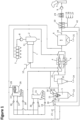
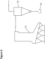
- FIG. 1 shows a first example of an inventive apparatus to put the inventive method into practice.
- the apparatus comprises a drum dryer 1, a discharge housing 2, a cleaning apparatus 3 (cyclone battery), two heat-exchangers 4 which are operated in parallel, a multi fuel burner 5 with a combustion chamber for combusting a fuel/combustion air mixture, a filter 6 as well as a chimney 7.
- the drying vapors generated by the drying of e.g. wooden chips inside the drum dryer 1 are lead in a drying circuit.
- a drying vapor fan 8 is arranged between the drum dryer 1 and the cleaning apparatus 3, a burner exhaust fan 9 is arranged between filter 6 and chimney 7.
- Dryer 1 may be provided with a slow-down zone 11 and a metering device 12.
- the drum dryer 1 is supplied with bulk goods, as for example with wooden chips and/or wooden fibers.
- the drying gases which are supplied to the drum dryer 1 are heated-up via the heat exchanger 4 and have temperatures in the range of approximately 250° C up to approximately 600° C.
- the heating of the drying gases in the heat-exchangers 4 is achieved in cross counter flow by means of exhaust gases from the combustion chamber generated by the multi-fuel burner 5.
- the exhaust gases have temperatures in the range of approximately 750° C up to approximately 900° C.
- temperatures of approximately 750° C up to 1050° C are achieved, wherein as fuel for example natural gas, oil and/or wood dust or other waste materials from the production of wooden material boards may be used.
- the different fuels may be used alone or in any combination with each other.
- one slow-down zone 11 may be provided for the drying goods and/or a discharge housing 2 to remove the dried bulk goods.
- the drying gases or the drying vapors, respectively, are driven via the drying vapor fan 8 to one or more cleaning apparatuses 3, preferably cyclone separators.
- a drying vapor fan may be arranged between the cleaning device 3 and the heat exchanger 4.
- fine dust and other particles are separated.
- the separated material may then advantageously be passed to the production or combusted in a hot gas generator such as e.g. the multi-fuel burner 5.
- a hot gas generator such as e.g. the multi-fuel burner 5.
- the drying vapors are heated from approximately 110° C to 130° C up to 250° C to approximately 600° C. This is done in a cross counter flow operation by means of the exhaust gases of the multi-fuel burner 5 from the combustion chamber. Inside of the heat-exchangers 4 a part of the vapor is separated (branch line 22) and led to the multi-fuel burner 5 as combustion air and/or cooling air. The air-feed of the multi-fuel burner 5 will be discussed in greater detail below. This part of the vapor is driven by the regulable partial vapor fan 40.
- the apparatus according to FIG. 1 comprises a first grate fired hot gas generator 31 which is aligned in parallel to the multi-fuel burner 5.
- This grate fired hot gas generator 31 is fed with solid combustible material, which e.g. can be waste wooden material etc. This material can be coarser than the material used as fuel for the multi-fuel burner 5 and comprises e.g. wooden chips or even wooden boards.
- the presence of the grate fired hot gas generator 31 therefore especially allows for the complete thermal recycling of materials which are e.g. generated anywhere during the production processes of chipboards or wooden articles.
- the grate fired hot gas generator 31 is operated with primary gas 39 which can be e.g. fresh ambient air 13.
- the primary gas can be tempered to elevated temperatures, alternatively the primary air can be used as taken from the surrounding.
- the grate fired hot gas generator 31 is supplied with a partial stream 22 of dryer gases via a separate regulable partial vapor fan 36 or 37.
- the vapor gases branched off the heat exchanger 4 can be added to the grate fired hot gas generator 31 as secondary air 37 or tertiary air 36.
- the apparatus as shown in Fig. 1 additionally comprises a hot gas cyclone 32 into which both the exhaust gas produced by the multi-fuel burner 5 and the first grate fired hot gas generator 31 are fed and cleaned from solid particles which are entrained in the exhaust gas of said hot gas generators, such as e.g. ashes, soot, carbon black etc..
- the collected solids are discharged via lock 34.
- the exhaust gases generated by the grate fired hot gas generator 31 are also led to the hot gas cyclone 32, which is also used to clean the exhaust gases of the multi-fuel burner 5. Accordingly, this assembly enables a parallel operation of the multi-fuel burner 5 and the grate fired hot gas generator 31. This assembly also allows the alternative operation of the multi-fuel burner 5 or the grate fired hot gas generator 31.
- the gases cleaned by the hot gas cyclone 32 are subsequently used to heat the vapor gases for drying the wooden chips and/or fibers inside the drum dryer 1 by indirect heat exchanging inside the heat exchangers 4.
- the exhaust gases of both the multi-fuel burner 5 and the grate fired hot gas generator 31, which serve to heat-up the drying gases in heat-exchangers 4, are guided - after passing through the heat-exchangers 4 - to a filter 6.
- This is in particular an electrostatic precipitator, preferably a dry type electrostatic precipitator.
- the filter 6 is preferably operated in a suction operation, whereby after the filter 6 a fan 9 for the exhaust gas of the hot gas generators is provided. The thus cleaned exhaust gas of the hot gas generators is released via chimney 7 into the environment.
- the multi-fuel burner 5 comprises a muffle 21, in which the combustion is taking place.
- the gases 13, 16, 17 and/or 27 can be used as primary air and fed into the muffle 21 as combustion air. Inside the muffle combustion air/fuel mixture is ignited and combusted. The mixing of the primary air and the fuel is not displayed in Fig. 4 .
- This primary air can be propelled by separate primary air fan 18.
- drying vapors, which are branched off at 22 from the heat exchangers 4 can be used as cooling air 38 and fed into the multi-fuel burner 5 via a cooling air fan 40 at an outer nozzle ring 30.
- the multi-fuel burner 5 is also provided with an inner nozzle ring, into which muffle cooling air can be supplied via a muffle cooling air fan 41.
- muffle cooling air e. g. fresh ambient air 25 and/or exhaust gases provided by an additional grate fired hot gas generator 31' can be used.
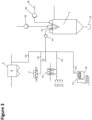
- the apparatus according to Fig. 4 comprises an additional grate fired hot gas generator 31', which can be provided with the same gas streams as the grate fired hot gas generator 31.
- the grate fired hot gas generator 31' comprises an additional thermal oil boiler house 28, in which heat exchangers for recuperation of the thermal energy of the exhaust gases or generated by the grate fired hot gas generator 31' are provided.
- the exhaust gas stream 20 is divided into two parts. A first part is used as muffle cooling air for the multi-fuel burner and added through the inner nozzle ring by means of the muffle cooling air fan 41. The second part of the exhaust gas stream 20 is directly led to the filter 6 and thermally exploited in the heat exchanger 19.
- the primary air 39 fed to the grate fired hot gas generator 31 preferably can be preheated by means of a heat exchanger 19, which is aligned downstream of the filter 6.
- the filtered exhaust gases 24 are led through the heat exchanger 19, accordingly fresh ambient air 13 can be preheated before being fed to the hot gas generator 31.
- additional air-streams such as press or saw exhaust gases 16, sanding line exhaust gases 17 and/or exhaust gases from a group production line 27 can be preheated in the heat exchanger 19 and fed to the grate fired hot gas generator 31 as primary air.
- the aforementioned gases 13, 16, 17 and 27 can also be used as secondary air 37 and/or tertiary air 36 and fed to the grate fired hot gas generator above the primary firing zone.
- the secondary and/or tertiary gas streams are to reduce the nitrogen oxide content of the exhaust gases generated by the grate fired hot gas generator 31 and/or are used as cooling air.
- a further heat exchanger 29 is aligned, in which e. g. hot water or hot thermal oil can be produced. Accordingly, a further energetic exploitation of the thermal energy still contained in the exhaust gas stream can be provided.
- the drying of the wood chips is done in a dedicated vapor circuit.
- a high vapor content can advantageously be achieved and thus a gentle drying can be realized, which has a positive effect on the quality of the drying goods.
- the pollution and thus the wear of the drying circuit can be kept to a minimum.
- the fire protection can be improved due to the indirect heating of the dryer and the dedicated drying circuit.
- the regulation (i.e. control) of the regulable partial vapor fan 40 is done in a preferred embodiment via the pollution level of the exhaust gases of the burner, as for example by means of the concentration of nitrogen oxides and/or the concentration values of carbon monoxide. Further, the regulable partial vapor fan may be controlled via a maximum inert gas content in the drying circuit or via the oxygen content in the exhaust gas of the multi-fuel burner 5.
- the supply of the drum dryer 1 with bulk goods is done while controlling the water content in the dryer by means of the metering device 12, whereby the bulk goods are metered depending on the moisture of different bulk good fractions upon supply to the drum dryer 1.
- different exhaust gases from the manufacturing of the wooden material boards are used as combustion air for the multi-fuel burner 5, as for example exhaust gases from the press arrangements, exhaust gases from the sawing arrangements and/or exhaust gases from the boiler.
- the different exhaust gases are preferably pre-heated before they are supplied as combustion air, in particular by means of heat-exchangers. These gases also can be supplied to a grate fired hot gas generator 31.
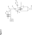
- Fig. 2 shows details of Fig. 1 , in which the air supply of the multi-fuel burner 5 is displayed in greater detail.
- the multi-fuel burner 5 has three distinct air-supplies, namely the supply of primary air, which can be fed by primary air fan 18.
- the primary air is fed directly into the muffle 21, in which a mixture of the primary air and the fuel is generated and ignited.
- the multi-fuel burner 5 is supplied with cooling air 38 which can be supplied to the multi-fuel burner 5 via outer nozzle rings and by means of regular level cooling air fan 40.
- the cooling air 38 can be e. g. branched off (see reference numerals 22 in Fig. 1 ) from the heat exchanger 4.
- the cooling air can effectively be used to cool the combustion chamber of the multi-fuel burner 5.
- the muffle 21 is provided with additional muffle cooling air, which is fed to the multi-fuel burner 5 via inner nozzle rings.
- This muffle cooling air directly is fed inside the muffle 21 and effectively cools the muffle.
- the muffle cooling air can be provided by means of a separate fan 41. At least a part of the muffle cooling air is generated by the hot gas generator 31' (see Fig. 1 ).
- muffle cooling air also e. g. ambient air 25, and drying vapors, which can be branched off (see reference numeral 22) from the heat exchanger 4 can be used.
- also cleaned exhaust gases which can be stripped off from the exhaust gas stream after the filter 6 can be used.
- pre-heated gases provided as gas stream 42 after the heat exchanger 19 can be used.
- these gases can be pre-heated ambient air 13, press and/or saw exhaust gases 16, sending aligned exhaust gases 17 and/or exhaust gases from a group production line 27.
- ambient air 25 can be used in addition to the pre-heated gas stream 42 as primary air used in a multi-fuel burner 5.
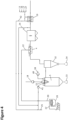
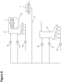
- Fig.8 shows an embodiment, in which two grate fired hot gas generators 31 and 31' are supplied with branched off gases (reference numeral 22) from the heat exchanger 4, both as secondary air 37 and tertiary air 36.
- Fig. 9 shows in detail the electrostatic filter 6, which has also been discussed in the foregoing figures, as well as a heat exchanger 29, which is aligned downstream of the electrostatic filter 6. Said heat exchanger 29 is used for recuperation of thermal energy contained in the exhaust gas stream 24. Furthermore, the exhaust fan 9 is used to operate electrostatic filter as well as the heat exchanger 29.
Landscapes
- Engineering & Computer Science (AREA)
- Mechanical Engineering (AREA)
- General Engineering & Computer Science (AREA)
- Chemical & Material Sciences (AREA)
- Combustion & Propulsion (AREA)
- Life Sciences & Earth Sciences (AREA)
- Sustainable Development (AREA)
- Drying Of Solid Materials (AREA)
Claims (15)
- Vorrichtung zum Trocknen von Schüttgut, insbesondere von Holzfasern und/oder Holzspänen, umfassend:mindestens einen Trockner (1), insbesondere einen Trommeltrockner,mindestens einen Heißgaserzeuger (5, 31, 31') undmindestens einen Wärmetauscher (4), der bereitgestellt ist, um ein Dampf-Gas-Gemisch zum Trocknen des Schüttguts in dem Trockner (1) indirekt zu erwärmen, wobei der mindestens eine Wärmetauscher durch Abgase erwärmt wird, die von dem mindestens einen Heißgaserzeuger (5, 31, 31') erzeugt werden,mindestens eine Zweigleitung (22) zu dem mindestens einen Heißgaserzeuger (5, 31, 31'), stromaufwärts, stromabwärts und/oder innerhalb des mindestens einen Wärmetauschers (4), um einen Teilstrom des Dampf-Gas-Gemisches abzuzweigen, undmindestens eine Leitung für den restlichen Teilstrom zu dem Trockner (1),wobeimindestens ein Mehrstoffbrenner (5) und mindestens ein mit Feststoff befeuerter Heißgaserzeuger (31, 31') umfasst sind, die für einen unabhängigen oder parallelen Betrieb eingerichtet sind, wobei der mindestens eine Mehrstoffbrenner (5) eine Brennkammer umfasst mit einer Muffel (21), in der ein Brennstoff/Verbrennungsluft-Gemisch entzündet und verbrannt wird, und einer Brennkammerdecke, wobei die Brennkammerdecke umfasst:- mindestens einen Einlass für Verbrennungsluft in die Muffel (21),- einen äußeren Düsenring (30), der einen Einlass für ein Kühlgas rings um die Muffel (21) bildet, und- einen inneren Düsenring, der einen Einlass für ein Kühlgas innerhalb der Muffel (21) bildet, das einen laminaren Strom von Kühlgas entlang der Muffel (21) bereitstellt,wobei der innere und der äußere Düsenring (30) separat steuerbar sind und der innere Düsenring mit von dem mindestens einen mit Feststoff befeuerten Heißgaserzeuger (31, 31') ausgestoßenem Gas, mit Umgebungsluft (13, 25) und/oder mit aus externen Produktionsprozessen (16, 17, 27) stammenden Gasen gespeist wird.
- Vorrichtung nach Anspruch 1, dadurch gekennzeichnet, dass der mindestens eine mit Feststoff befeuerte Heißgaserzeuger (31, 31') ein Heißgaserzeuger mit Rostbefeuerung, ein Heißgaserzeuger mit Wirbelschichtverbrennung und/oder ein Heißgaserzeuger mit Stokerbefeuerung ist.
- Vorrichtung nach einem der vorangehenden Ansprüche, dadurch gekennzeichnet, dassmindestens ein Heißgaszyklon (32) zwischen dem mindestens einen Heißgaserzeuger (5, 31, 31') und dem mindestens einen Wärmetauscher (4) bereitgestellt ist, so dass die von dem mindestens einen Heißgaserzeuger (5, 31, 31') produzierten Abgase durch den mindestens einen Heißgaszyklon (32) geleitet werden,mindestens ein Filter (6), insbesondere ein elektrostatischer Abscheider, vorzugsweise ein elektrostatischer Trockenabscheider zum Reinigen von Abgasen, die von dem mindestens einen Heißgaserzeuger (5, 31, 31') erzeugt werden, bereitgestellt ist; und stromabwärts von dem mindestens einen Filter (6) mindestens ein Wärmetauscher (19) bereitgestellt ist, der Gase (13, 16, 17, 27) indirekt erwärmt, die als Beschickungsluft (18, 36, 37, 39) für den mindestens einen Heißgaserzeuger (5, 31, 31') verwendet werden, wobei der mindestens eine Wärmetauscher (19) durch die Abgase erwärmt wird, und/oderein Heißgaserzeuger-Abgasgebläse (9) stromabwärts von dem Filter (6) positioniert ist.
- Vorrichtung nach einem der vorangehenden Ansprüche, dadurch gekennzeichnet, dass der innere und/oder äußere Düsenring einen Eintrittswinkel von ungefähr 0 Grad bis ungefähr 60 Grad, vorzugsweise zwischen 10 bis 60 Grad umfassen (30).
- Vorrichtung nach einem der vorangehenden Ansprüche, dadurch gekennzeichnet, dassder mindestens eine Heißgaserzeuger (5, 31, 31') mit Gasen gespeist wird, die aus externen Produktionsprozessen (16, 17, 27) stammen,der mindestens eine mit Feststoff befeuerte Heißgaserzeuger (31, 31') über die Zweigleitung (22) mit einem Teilstrom des Dampf-Gas-Gemisches als primäres (39), sekundäres (37) und/oder tertiäres Gas (36) beliefert wird.
- Vorrichtung nach einem der vorangehenden Ansprüche, dadurch gekennzeichnet, dass mindestens ein Wärmetauscher (29) bereitgestellt ist, der eine Flüssigkeit indirekt erwärmt, wobei der mindestens eine Wärmetauscher durch die Abgase erwärmt wird, wobei der mindestens eine Wärmetauscher (29) vorzugsweise stromabwärts von dem mindestens einen Filter (6) angeordnet ist.
- Vorrichtung nach einem der vorangehenden Ansprüche, dadurch gekennzeichnet, dass in der Zweigleitung (22) zu dem Heißgaserzeuger (5, 31, 31') mindestens ein regulierbares Teildampfgebläse (36, 37, 39, 40) bereitgestellt ist, das vorzugsweise regulierbar ist durch mindestens eines von:einem Verschmutzungsgrad in dem von dem mindestens einen Heißgaserzeuger (5, 31, 31') produzierten Abgas, insbesondere durch einen Stickoxidpegel und/oder Kohlenmonoxidpegel in dem Abgas,einem Sauerstoffgehalt in dem Abgas, das von dem mindestens einen Heißgaserzeuger (5, 31, 31') erzeugt wird, und/odereinem maximalen Inertgasgehalt in dem Dampf-Gas-Gemisch zum Trocknen des Schüttguts in dem Trockner (1).
- Vorrichtung nach einem der vorangehenden Ansprüche, dadurch gekennzeichnet, dasszum Reinigen des aus dem mindestens einen Trockner (1) abgegebenen Dampf-Gas-Gemisches eine Reinigungseinrichtung (3) bereitgestellt ist, insbesondere mindestens ein Zyklon, vorzugsweise mindestens eine Zyklonbatterie,stromabwärts von dem Trockner (1) mindestens ein Trocknungsdampfgebläse (8) bereitgestellt ist und/oderzum Regulieren des Wassergehalts in dem Trockner (1) eine Dosiereinrichtung (12) bereitgestellt ist.
- Anordnung für die Herstellung von Platten aus Holzmaterial mit mindestens einer Zerkleinerungsvorrichtung, mindestens einer Vorrichtung zum Trocknen von Schüttgut gemäß einem der vorangehenden Ansprüche und mindestens einer Presseinrichtung.
- Verfahren zum kontinuierlichen Trocknen von Schüttgut, insbesondere von Holzfasern und/oder Holzspänen, in einem Trockner (1), insbesondere einem Trommeltrockner, der mit Schüttgut beschickt wird und durch den ein Dampf-Gas-Gemisch in einem Trocknungskreislauf strömt, wobei das Dampf-Gas-Gemisch indirekt über mindestens einen Wärmetauscher (4) durch Abgase erwärmt wird, die von mindestens einem Heißgaserzeuger (5, 31, 31') produziert werden, und wobei das Dampf-Gas-Gemisch in dem mindestens einen Wärmetauscher (4) geführt und erwärmt wird, und wobei stromaufwärts, stromabwärts und/oder innerhalb des mindestens einen Wärmetauschers (4) zumindest ein Teilstrom des Dampf-Gas-Gemisches abgezweigt wird (22), um in den mindestens einen Heißgaserzeuger (5, 31, 31') geleitet zu werden,
wobeider mindestens eine mindestens eine Heißgaserzeuger (5, 31, 31') mindestens einen Mehrstoffbrenner (5) und mindestens einen mit Feststoff befeuerten Heißgaserzeuger (31, 31') umfasst, die für einen unabhängigen oder parallelen Betrieb eingerichtet sind, wobei der mindestens eine Mehrstoffbrenner (5) eine Brennkammer umfasst mit einer Muffel (21), in der ein Brennstoff/Verbrennungsluft-Gemisch entzündet und verbrannt wird, und einer Brennkammerdecke, wobei die Brennkammerdecke umfasst:- mindestens einen Einlass (18) für Verbrennungsluft in die Muffel,- einen äußeren Düsenring (30), der einen Einlass für ein Kühlgas rings um die Muffel bildet, und- einen inneren Düsenring, der einen Einlass für ein Kühlgas innerhalb der Muffel (21) bildet, das einen laminaren Strom von Kühlgas entlang der Muffel bereitstellt,wobei der innere und der äußere Düsenring (30) separat gesteuert werden und der innere Düsenring mit Gas, das von dem mindestens einen mit Feststoff befeuerten Heißgaserzeuger (31') ausgestoßen wird, mit Umgebungsluft (13, 25) und/oder mit aus externen Produktionsprozessen (16, 17, 27) stammenden Gasen gespeist wird. - Verfahren nach Anspruch 10, dadurch gekennzeichnet, dass der mindestens eine mit Feststoff befeuerte Heißgaserzeuger (31, 31'), ein Heißgaserzeuger mit Rostfeuerung, ein Heißgaserzeuger mit Wirbelschichtverbrennung und/oder ein Heißgaserzeuger mit Stoker-Befeuerung ist, der mit Biomasse, insbesondere mit Holzbiomasse befeuert wird.
- Verfahren nach einem der Ansprüche 10 bis 11, dadurch gekennzeichnet, dassdie Abgase, die von mindestens einem Heißgaserzeuger (5, 31, 31') produziert werden, durch mindestens einen Heißgaszyklon (32) geleitet werden, der zwischen dem mindestens einen Heißgaserzeuger (5, 31, 31') und dem mindestens einen Wärmetauscher (4) bereitgestellt ist,die Abgase, die von dem mindestens einen Heißgaserzeuger (5, 31, 31') erzeugt werden, durch mindestens einen Filter (6), insbesondere einen elektrostatischen Abscheider, vorzugsweise einen elektrostatischen Trockenabscheider, gereinigt werden; und stromabwärts von dem mindestens einen Filter (6) die von dem mindestens einen Heißgaserzeuger (5, 31, 31') erzeugten Abgase verwendet werden, um Gase (13,16, 17, 27), die als Beschickungsluft (18, 36, 37, 39) für den mindestens einen Heißgaserzeuger (5, 31, 31') verwendet werden, mittels mindestens eines Wärmetauschers (19) indirekt zu erwärmen,der Filter (6) in einem Saugmodus betrieben wird, wobei vorzugsweise mindestens ein Heißgaserzeuger-Abgasgebläse (9) stromabwärts von dem Filter (6) angeordnet ist, und/oderder innere und/oder der äußere Düsenring (30) einen Eintrittswinkel zwischen ungefähr 0 und ungefähr 60 Grad, vorzugsweise zwischen 10 und 60 Grad aufweist (aufweisen), wobei dieser Winkel vorzugsweise abhängig von dem verwendeten Brennstoff anpassbar ist.
- Verfahren nach einem der Ansprüche 10 bis 12, dadurch gekennzeichnet, dassder mindestens eine Heißgaserzeuger (5, 31, 31') mit Gasen gespeist wird, die aus externen Produktionsprozessen (16, 17, 27) stammen,der mindestens eine mit Feststoff befeuerte Heißgaserzeuger (31, 31') über die Zweigleitung (22) mit einem Teilstrom des Dampf-Gas-Gemisches als primäres (39), sekundäres (37) und/oder tertiäres Gas (36) beliefert wird,eine Flüssigkeit mittels mindestens eines Wärmetauschers (29) durch die Abgase indirekt erwärmt wird, wobei der mindestens eine Wärmetauscher (29) vorzugsweise stromabwärts von dem mindestens einen Filter (6) angeordnet ist,der Teilstrom zu dem mindestens einen Heißgaserzeuger (5, 31, 31') mittels mindestens eines regulierbaren Teildampfgebläses (36, 37, 39, 40) getrieben wird, wobei vorzugsweise das Teildampfgebläse (36, 37, 39, 40) reguliert wird über mindestens eines voneinem Verschmutzungsgrad des von dem mindestens einen Heißgaserzeuger (5, 31, 31') produzierten Abgases, insbesondere durch Stickoxide und/oder Kohlenmonoxide in dem Abgas, und/odereinem Sauerstoffgehalt in dem Abgas, das von dem mindestens einen Heißgaserzeuger (5, 31, 31') erzeugt wird, und/odereinem maximalen Inertgasgehalt in dem Dampf-Gas-Gemisch innerhalb des Trocknungskreislaufs.
- Verfahren nach einem der Ansprüche 10 bis 13, dadurch gekennzeichnet, dasszumindest zum Teil Feststoffe, insbesondere Biomasse, als Brennstoff für den mindestens einen Heißgaserzeuger (5, 31, 31') verwendet werden, wobei vorzugsweise Abfallprodukte aus der Produktion der Platten aus Holzmaterial verwendet werden,das Dampf-Gas-Gemisch nach Durchströmen des Trockners (1) gereinigt wird, wobei als Reinigungsvorrichtung (3) mindestens ein Zyklon, insbesondere mindestens eine Zyklonbatterie, verwendet wird,das Dampf-Gas-Gemisch nach dem Trockner (1) von mindestens einem Trockendampfgebläse (8) getrieben wird, und/oderder Wassergehalt in dem Trockner (1) reguliert wird, wobei das Schüttgut vorzugsweise abhängig von der Feuchtigkeit verschiedener Schüttgutfraktionen bei Beschickung des Trockners (1) dosiert wird.
- Verfahren zum Herstellen von Platten aus Holzmaterial, wobei Holzblöcke entrindet und in einer Zerkleinerungsvorrichtung zu Holzspänen und/oder -fasern verarbeitet werden, wobei die Holzspäne und/oder - fasern in einer Trocknungsvorrichtung getrocknet werden, wobei die getrockneten Holzspäne und/oder -fasern in einer Pressenanordnung zu Platten verarbeitet werden, falls notwendig unter Zugabe von Bindemitteln und/oder anderen Zusätzen, und vorzugsweise zugeschnitten werden, dadurch gekennzeichnet, dass das Trocknen der Holzspäne und/oder -fasern in einer Vorrichtung nach einem der Ansprüche 1 bis 9 ausgeführt wird und/oder zum Trocknen der Holzspäne und/oder -fasern ein Verfahren nach einem der Ansprüche 10 bis 14 ausgeführt wird.
Priority Applications (4)
| Application Number | Priority Date | Filing Date | Title |
|---|---|---|---|
| HRP20250630TT HRP20250630T1 (hr) | 2017-03-03 | 2017-03-03 | Aparatura i postupak za kontinurano sušenje rasutih materijala, naročito drvene sječke i drvenih vlakana , koji obuhvaća višegorivni plamenik sa sustavom hlađenja s prigušivačem |
| HUE17708525A HUE071509T2 (hu) | 2017-03-03 | 2017-03-03 | Berendezés és eljárás ömlesztett áru, különösen faforgács és/vagy fa anyagú szálak folyamatos szárítására, többféle tüzelõanyaggal mûködõ égõvel és tokos hûtõberendezéssel |
| PL17708525.5T PL3589892T3 (pl) | 2017-03-03 | 2017-03-03 | Urządzenie do i sposób suszenia ciągłego materiałów masowych, w szczególności wiórów drzewnych i/albo włókien drzewnych, zawierające palinik wielopaliwowy z sytemem chłodzącym muflęsystem |
| RS20250514A RS66835B1 (sr) | 2017-03-03 | 2017-03-03 | Aparatura i postupak za kontinurano sušenje rastresitog materijala, naročito drvene sečke i drvenih vlakana, koji obuhvata višegorivni gorionik sa mufelnim rashladnim sistemom |
Applications Claiming Priority (1)
| Application Number | Priority Date | Filing Date | Title |
|---|---|---|---|
| PCT/EP2017/055074 WO2018157949A1 (en) | 2017-03-03 | 2017-03-03 | Apparatus and method for continuously drying bulk goods, in particular wood chips and/or wood fibers comprising multi-fuel burner with a muffle cooling system |
Publications (3)
| Publication Number | Publication Date |
|---|---|
| EP3589892A1 EP3589892A1 (de) | 2020-01-08 |
| EP3589892C0 EP3589892C0 (de) | 2025-04-23 |
| EP3589892B1 true EP3589892B1 (de) | 2025-04-23 |
Family
ID=58213107
Family Applications (1)
| Application Number | Title | Priority Date | Filing Date |
|---|---|---|---|
| EP17708525.5A Active EP3589892B1 (de) | 2017-03-03 | 2017-03-03 | Vorrichtung und verfahren zum kontinuierlichen trocknen von schüttgut, insbesondere von holzspänen und/oder holzfasern, mit einem mehrstoffbrenner mit einem muffelkühlsystem |
Country Status (12)
| Country | Link |
|---|---|
| US (1) | US11079106B2 (de) |
| EP (1) | EP3589892B1 (de) |
| CN (1) | CN110382957A (de) |
| CA (1) | CA3053986C (de) |
| EA (1) | EA039553B1 (de) |
| ES (1) | ES3030499T3 (de) |
| HR (1) | HRP20250630T1 (de) |
| HU (1) | HUE071509T2 (de) |
| PL (1) | PL3589892T3 (de) |
| RS (1) | RS66835B1 (de) |
| UA (1) | UA124778C2 (de) |
| WO (1) | WO2018157949A1 (de) |
Families Citing this family (5)
| Publication number | Priority date | Publication date | Assignee | Title |
|---|---|---|---|---|
| EP3589891B1 (de) | 2017-03-03 | 2024-11-20 | Kronoplus Limited | Vorrichtung und verfahren zum kontinuierlichen trocknen von schüttgut, insbesondere holzspänen und/oder holzfasern, mit einem festen befeuerten heissgasgenerator |
| CN110382961A (zh) | 2017-03-03 | 2019-10-25 | 道格拉斯科技有限公司 | 用于连续干燥散装物品、特别是木屑和/或木纤维的包括热气旋风分离器的设备和方法 |
| US11248845B2 (en) | 2017-03-03 | 2022-02-15 | Douglas Technical Limited | Apparatus and method for continuously drying bulk goods, in particular wood chips and/or wood fibers comprising a heat exchanger |
| CA3063517C (en) | 2017-06-06 | 2023-08-01 | Douglas Technical Limited | Apparatus and method for continuously drying bulk goods |
| US10883762B1 (en) * | 2018-01-17 | 2021-01-05 | University Of Puerto Rico | Continuous granulo-dryer for the manufacturing of pharmaceutical products via wet granulation |
Family Cites Families (19)
| Publication number | Priority date | Publication date | Assignee | Title |
|---|---|---|---|---|
| US653819A (en) * | 1899-11-09 | 1900-07-17 | Louis Hubert Willem Regout | Muffle furnace or oven. |
| US2753925A (en) * | 1951-07-05 | 1956-07-10 | Sinclair Refining Co | Carbon monoxide burner |
| DE2734973C2 (de) * | 1977-08-03 | 1982-12-16 | Kernforschungsanlage Jülich GmbH, 5170 Jülich | Verfahren und Verbrennungsofen zum Verbrennen von Abfällen |
| DE3729971A1 (de) | 1987-09-08 | 1989-03-16 | Wuenning Joachim | Heissgaserzeugungseinrichtung mit thermischer nachverbrennung |
| CH676500A5 (de) | 1990-05-18 | 1991-01-31 | Werner Kunz | |
| DE4017806A1 (de) | 1990-06-01 | 1991-12-05 | Koerting Ag | Verfahren und anlage zur kontinuierlichen trocknung von holzspaenen, holzfasern oder anderen schuettguetern |
| DE59501167D1 (de) | 1994-11-24 | 1998-02-05 | Kunz Drytec Ag W | Verfahren zum Trocknen einer Substanz, insbesondere von Holzspänen |
| DK1946006T3 (da) | 2005-09-27 | 2009-12-21 | Dall Energy Holding Aps | Fremgangsmåde og system til opvarmning af vand baseret på varme gasser |
| US7531769B2 (en) * | 2006-06-13 | 2009-05-12 | Guy Smith | Carbon fiber composite muffle |
| US20080271335A1 (en) * | 2007-05-03 | 2008-11-06 | Archer-Daniele-Midland Company | System for using heat to process an agricultural product, a fluidized bed combustor system, and methods of employing the same |
| EP2388542B1 (de) | 2008-01-10 | 2015-09-02 | Douglas Technical Limited | Verfahren und Vorrichtung zur kontinuierlichen Trocknung von Schüttgut, insbesondere von Holzfasern und/oder Holzspänen |
| GB0902629D0 (en) | 2009-02-17 | 2009-04-01 | Dickinson Legg Ltd | Tabacco drying apparatus |
| HUE024574T2 (en) * | 2009-03-10 | 2016-02-29 | Kronotec Ag | Wood chips dryer for drying wood chips and a method for drying wood chips |
| DE102010014479B4 (de) | 2010-04-09 | 2012-01-12 | Fritz Egger Gmbh & Co. Og | Vorrichtung und Verfahren zur Heißgaserzeugung mit integrierter Erhitzung eines Wärmeträgermediums |
| CN103471369A (zh) * | 2013-09-05 | 2013-12-25 | 山东天力干燥股份有限公司 | 一种用过热蒸汽携湿的蒸汽回转干燥工艺及褐煤干燥方法 |
| CN105240859A (zh) * | 2015-10-30 | 2016-01-13 | 大连科林能源工程技术开发有限公司 | 一种能量自给型化工污泥干化焚烧系统 |
| CN110382961A (zh) | 2017-03-03 | 2019-10-25 | 道格拉斯科技有限公司 | 用于连续干燥散装物品、特别是木屑和/或木纤维的包括热气旋风分离器的设备和方法 |
| US11248845B2 (en) | 2017-03-03 | 2022-02-15 | Douglas Technical Limited | Apparatus and method for continuously drying bulk goods, in particular wood chips and/or wood fibers comprising a heat exchanger |
| EP3589891B1 (de) | 2017-03-03 | 2024-11-20 | Kronoplus Limited | Vorrichtung und verfahren zum kontinuierlichen trocknen von schüttgut, insbesondere holzspänen und/oder holzfasern, mit einem festen befeuerten heissgasgenerator |
-
2017
- 2017-03-03 HU HUE17708525A patent/HUE071509T2/hu unknown
- 2017-03-03 HR HRP20250630TT patent/HRP20250630T1/hr unknown
- 2017-03-03 CN CN201780087873.2A patent/CN110382957A/zh active Pending
- 2017-03-03 WO PCT/EP2017/055074 patent/WO2018157949A1/en not_active Ceased
- 2017-03-03 US US16/489,369 patent/US11079106B2/en active Active
- 2017-03-03 CA CA3053986A patent/CA3053986C/en active Active
- 2017-03-03 PL PL17708525.5T patent/PL3589892T3/pl unknown
- 2017-03-03 EP EP17708525.5A patent/EP3589892B1/de active Active
- 2017-03-03 ES ES17708525T patent/ES3030499T3/es active Active
- 2017-03-03 UA UAA201909480A patent/UA124778C2/uk unknown
- 2017-03-03 EA EA201991751A patent/EA039553B1/ru unknown
- 2017-03-03 RS RS20250514A patent/RS66835B1/sr unknown
Also Published As
| Publication number | Publication date |
|---|---|
| EA201991751A1 (ru) | 2020-02-28 |
| WO2018157949A1 (en) | 2018-09-07 |
| RS66835B1 (sr) | 2025-06-30 |
| PL3589892T3 (pl) | 2025-06-23 |
| US11079106B2 (en) | 2021-08-03 |
| ES3030499T3 (en) | 2025-06-30 |
| CA3053986C (en) | 2023-03-07 |
| US20200011528A1 (en) | 2020-01-09 |
| HUE071509T2 (hu) | 2025-09-28 |
| CA3053986A1 (en) | 2018-09-07 |
| CN110382957A (zh) | 2019-10-25 |
| EP3589892C0 (de) | 2025-04-23 |
| UA124778C2 (uk) | 2021-11-17 |
| EA039553B1 (ru) | 2022-02-09 |
| EP3589892A1 (de) | 2020-01-08 |
| HRP20250630T1 (hr) | 2025-07-18 |
Similar Documents
| Publication | Publication Date | Title |
|---|---|---|
| EP3589891B1 (de) | Vorrichtung und verfahren zum kontinuierlichen trocknen von schüttgut, insbesondere holzspänen und/oder holzfasern, mit einem festen befeuerten heissgasgenerator | |
| US11543124B2 (en) | Apparatus and method for continuously drying bulk goods, in particular wood chips and/or wood fibers comprising a hot gas cyclone | |
| US10690409B2 (en) | Method for continuously drying bulk goods, in particular wood fibers and/or wood chips | |
| EP3589890B1 (de) | Vorrichtung und verfahren zum kontinuierlichen trocknen von schüttgut, insbesondere holzspänen und/oder holzfasern, mit einem wärmetauscher | |
| EP3589892B1 (de) | Vorrichtung und verfahren zum kontinuierlichen trocknen von schüttgut, insbesondere von holzspänen und/oder holzfasern, mit einem mehrstoffbrenner mit einem muffelkühlsystem | |
| CA3063517C (en) | Apparatus and method for continuously drying bulk goods | |
| EA041059B1 (ru) | Устройство и способ непрерывной сушки сыпучих продуктов, в частности древесной стружки и/или древесных волокон, включающие циклон для горячего газа |
Legal Events
| Date | Code | Title | Description |
|---|---|---|---|
| REG | Reference to a national code |
Ref country code: HR Ref legal event code: TUEP Ref document number: P20250630T Country of ref document: HR |
|
| STAA | Information on the status of an ep patent application or granted ep patent |
Free format text: STATUS: UNKNOWN |
|
| STAA | Information on the status of an ep patent application or granted ep patent |
Free format text: STATUS: THE INTERNATIONAL PUBLICATION HAS BEEN MADE |
|
| PUAI | Public reference made under article 153(3) epc to a published international application that has entered the european phase |
Free format text: ORIGINAL CODE: 0009012 |
|
| STAA | Information on the status of an ep patent application or granted ep patent |
Free format text: STATUS: REQUEST FOR EXAMINATION WAS MADE |
|
| 17P | Request for examination filed |
Effective date: 20190904 |
|
| AK | Designated contracting states |
Kind code of ref document: A1 Designated state(s): AL AT BE BG CH CY CZ DE DK EE ES FI FR GB GR HR HU IE IS IT LI LT LU LV MC MK MT NL NO PL PT RO RS SE SI SK SM TR |
|
| AX | Request for extension of the european patent |
Extension state: BA ME |
|
| DAV | Request for validation of the european patent (deleted) | ||
| DAX | Request for extension of the european patent (deleted) | ||
| STAA | Information on the status of an ep patent application or granted ep patent |
Free format text: STATUS: EXAMINATION IS IN PROGRESS |
|
| 17Q | First examination report despatched |
Effective date: 20220621 |
|
| RAP1 | Party data changed (applicant data changed or rights of an application transferred) |
Owner name: KRONOPLUS LIMITED |
|
| GRAP | Despatch of communication of intention to grant a patent |
Free format text: ORIGINAL CODE: EPIDOSNIGR1 |
|
| STAA | Information on the status of an ep patent application or granted ep patent |
Free format text: STATUS: GRANT OF PATENT IS INTENDED |
|
| INTG | Intention to grant announced |
Effective date: 20240710 |
|
| GRAJ | Information related to disapproval of communication of intention to grant by the applicant or resumption of examination proceedings by the epo deleted |
Free format text: ORIGINAL CODE: EPIDOSDIGR1 |
|
| STAA | Information on the status of an ep patent application or granted ep patent |
Free format text: STATUS: EXAMINATION IS IN PROGRESS |
|
| INTC | Intention to grant announced (deleted) | ||
| GRAP | Despatch of communication of intention to grant a patent |
Free format text: ORIGINAL CODE: EPIDOSNIGR1 |
|
| STAA | Information on the status of an ep patent application or granted ep patent |
Free format text: STATUS: GRANT OF PATENT IS INTENDED |
|
| INTG | Intention to grant announced |
Effective date: 20241030 |
|
| GRAS | Grant fee paid |
Free format text: ORIGINAL CODE: EPIDOSNIGR3 |
|
| GRAA | (expected) grant |
Free format text: ORIGINAL CODE: 0009210 |
|
| STAA | Information on the status of an ep patent application or granted ep patent |
Free format text: STATUS: THE PATENT HAS BEEN GRANTED |
|
| AK | Designated contracting states |
Kind code of ref document: B1 Designated state(s): AL AT BE BG CH CY CZ DE DK EE ES FI FR GB GR HR HU IE IS IT LI LT LU LV MC MK MT NL NO PL PT RO RS SE SI SK SM TR |
|
| REG | Reference to a national code |
Ref country code: GB Ref legal event code: FG4D |
|
| REG | Reference to a national code |
Ref country code: CH Ref legal event code: EP |
|
| REG | Reference to a national code |
Ref country code: DE Ref legal event code: R096 Ref document number: 602017089035 Country of ref document: DE |
|
| REG | Reference to a national code |
Ref country code: IE Ref legal event code: FG4D |
|
| U01 | Request for unitary effect filed |
Effective date: 20250502 |
|
| U07 | Unitary effect registered |
Designated state(s): AT BE BG DE DK EE FI FR IT LT LU LV MT NL PT RO SE SI Effective date: 20250508 |
|
| REG | Reference to a national code |
Ref country code: ES Ref legal event code: FG2A Ref document number: 3030499 Country of ref document: ES Kind code of ref document: T3 Effective date: 20250630 |
|
| REG | Reference to a national code |
Ref country code: SK Ref legal event code: T3 Ref document number: E 46452 Country of ref document: SK |
|
| REG | Reference to a national code |
Ref country code: HR Ref legal event code: T1PR Ref document number: P20250630 Country of ref document: HR |
|
| REG | Reference to a national code |
Ref country code: HU Ref legal event code: AG4A Ref document number: E071509 Country of ref document: HU |
|
| PG25 | Lapsed in a contracting state [announced via postgrant information from national office to epo] |
Ref country code: GR Free format text: LAPSE BECAUSE OF FAILURE TO SUBMIT A TRANSLATION OF THE DESCRIPTION OR TO PAY THE FEE WITHIN THE PRESCRIBED TIME-LIMIT Effective date: 20250724 |
|
| PG25 | Lapsed in a contracting state [announced via postgrant information from national office to epo] |
Ref country code: IS Free format text: LAPSE BECAUSE OF FAILURE TO SUBMIT A TRANSLATION OF THE DESCRIPTION OR TO PAY THE FEE WITHIN THE PRESCRIBED TIME-LIMIT Effective date: 20250823 |