EP3589857B1 - Verfahren und vorrichtung zum betrieb eines antriebsstranges - Google Patents
Verfahren und vorrichtung zum betrieb eines antriebsstranges Download PDFInfo
- Publication number
- EP3589857B1 EP3589857B1 EP17709410.9A EP17709410A EP3589857B1 EP 3589857 B1 EP3589857 B1 EP 3589857B1 EP 17709410 A EP17709410 A EP 17709410A EP 3589857 B1 EP3589857 B1 EP 3589857B1
- Authority
- EP
- European Patent Office
- Prior art keywords
- piston
- clutch
- determined
- temperature
- sensor
- Prior art date
- Legal status (The legal status is an assumption and is not a legal conclusion. Google has not performed a legal analysis and makes no representation as to the accuracy of the status listed.)
- Active
Links
Images
Classifications
-
- F—MECHANICAL ENGINEERING; LIGHTING; HEATING; WEAPONS; BLASTING
- F16—ENGINEERING ELEMENTS AND UNITS; GENERAL MEASURES FOR PRODUCING AND MAINTAINING EFFECTIVE FUNCTIONING OF MACHINES OR INSTALLATIONS; THERMAL INSULATION IN GENERAL
- F16D—COUPLINGS FOR TRANSMITTING ROTATION; CLUTCHES; BRAKES
- F16D48/00—External control of clutches
- F16D48/06—Control by electric or electronic means, e.g. of fluid pressure
-
- F—MECHANICAL ENGINEERING; LIGHTING; HEATING; WEAPONS; BLASTING
- F16—ENGINEERING ELEMENTS AND UNITS; GENERAL MEASURES FOR PRODUCING AND MAINTAINING EFFECTIVE FUNCTIONING OF MACHINES OR INSTALLATIONS; THERMAL INSULATION IN GENERAL
- F16D—COUPLINGS FOR TRANSMITTING ROTATION; CLUTCHES; BRAKES
- F16D2500/00—External control of clutches by electric or electronic means
- F16D2500/10—System to be controlled
- F16D2500/102—Actuator
- F16D2500/1021—Electrical type
- F16D2500/1022—Electromagnet
-
- F—MECHANICAL ENGINEERING; LIGHTING; HEATING; WEAPONS; BLASTING
- F16—ENGINEERING ELEMENTS AND UNITS; GENERAL MEASURES FOR PRODUCING AND MAINTAINING EFFECTIVE FUNCTIONING OF MACHINES OR INSTALLATIONS; THERMAL INSULATION IN GENERAL
- F16D—COUPLINGS FOR TRANSMITTING ROTATION; CLUTCHES; BRAKES
- F16D2500/00—External control of clutches by electric or electronic means
- F16D2500/10—System to be controlled
- F16D2500/102—Actuator
- F16D2500/1021—Electrical type
- F16D2500/1023—Electric motor
- F16D2500/1024—Electric motor combined with hydraulic actuation
-
- F—MECHANICAL ENGINEERING; LIGHTING; HEATING; WEAPONS; BLASTING
- F16—ENGINEERING ELEMENTS AND UNITS; GENERAL MEASURES FOR PRODUCING AND MAINTAINING EFFECTIVE FUNCTIONING OF MACHINES OR INSTALLATIONS; THERMAL INSULATION IN GENERAL
- F16D—COUPLINGS FOR TRANSMITTING ROTATION; CLUTCHES; BRAKES
- F16D2500/00—External control of clutches by electric or electronic means
- F16D2500/10—System to be controlled
- F16D2500/102—Actuator
- F16D2500/1026—Hydraulic
-
- F—MECHANICAL ENGINEERING; LIGHTING; HEATING; WEAPONS; BLASTING
- F16—ENGINEERING ELEMENTS AND UNITS; GENERAL MEASURES FOR PRODUCING AND MAINTAINING EFFECTIVE FUNCTIONING OF MACHINES OR INSTALLATIONS; THERMAL INSULATION IN GENERAL
- F16D—COUPLINGS FOR TRANSMITTING ROTATION; CLUTCHES; BRAKES
- F16D2500/00—External control of clutches by electric or electronic means
- F16D2500/10—System to be controlled
- F16D2500/104—Clutch
- F16D2500/10406—Clutch position
- F16D2500/10412—Transmission line of a vehicle
-
- F—MECHANICAL ENGINEERING; LIGHTING; HEATING; WEAPONS; BLASTING
- F16—ENGINEERING ELEMENTS AND UNITS; GENERAL MEASURES FOR PRODUCING AND MAINTAINING EFFECTIVE FUNCTIONING OF MACHINES OR INSTALLATIONS; THERMAL INSULATION IN GENERAL
- F16D—COUPLINGS FOR TRANSMITTING ROTATION; CLUTCHES; BRAKES
- F16D2500/00—External control of clutches by electric or electronic means
- F16D2500/10—System to be controlled
- F16D2500/104—Clutch
- F16D2500/10443—Clutch type
- F16D2500/10462—Dog-type clutch
-
- F—MECHANICAL ENGINEERING; LIGHTING; HEATING; WEAPONS; BLASTING
- F16—ENGINEERING ELEMENTS AND UNITS; GENERAL MEASURES FOR PRODUCING AND MAINTAINING EFFECTIVE FUNCTIONING OF MACHINES OR INSTALLATIONS; THERMAL INSULATION IN GENERAL
- F16D—COUPLINGS FOR TRANSMITTING ROTATION; CLUTCHES; BRAKES
- F16D2500/00—External control of clutches by electric or electronic means
- F16D2500/10—System to be controlled
- F16D2500/106—Engine
- F16D2500/1066—Hybrid
-
- F—MECHANICAL ENGINEERING; LIGHTING; HEATING; WEAPONS; BLASTING
- F16—ENGINEERING ELEMENTS AND UNITS; GENERAL MEASURES FOR PRODUCING AND MAINTAINING EFFECTIVE FUNCTIONING OF MACHINES OR INSTALLATIONS; THERMAL INSULATION IN GENERAL
- F16D—COUPLINGS FOR TRANSMITTING ROTATION; CLUTCHES; BRAKES
- F16D2500/00—External control of clutches by electric or electronic means
- F16D2500/30—Signal inputs
- F16D2500/302—Signal inputs from the actuator
- F16D2500/3022—Current
-
- F—MECHANICAL ENGINEERING; LIGHTING; HEATING; WEAPONS; BLASTING
- F16—ENGINEERING ELEMENTS AND UNITS; GENERAL MEASURES FOR PRODUCING AND MAINTAINING EFFECTIVE FUNCTIONING OF MACHINES OR INSTALLATIONS; THERMAL INSULATION IN GENERAL
- F16D—COUPLINGS FOR TRANSMITTING ROTATION; CLUTCHES; BRAKES
- F16D2500/00—External control of clutches by electric or electronic means
- F16D2500/30—Signal inputs
- F16D2500/302—Signal inputs from the actuator
- F16D2500/3026—Stroke
-
- F—MECHANICAL ENGINEERING; LIGHTING; HEATING; WEAPONS; BLASTING
- F16—ENGINEERING ELEMENTS AND UNITS; GENERAL MEASURES FOR PRODUCING AND MAINTAINING EFFECTIVE FUNCTIONING OF MACHINES OR INSTALLATIONS; THERMAL INSULATION IN GENERAL
- F16D—COUPLINGS FOR TRANSMITTING ROTATION; CLUTCHES; BRAKES
- F16D2500/00—External control of clutches by electric or electronic means
- F16D2500/30—Signal inputs
- F16D2500/302—Signal inputs from the actuator
- F16D2500/3028—Voltage
-
- F—MECHANICAL ENGINEERING; LIGHTING; HEATING; WEAPONS; BLASTING
- F16—ENGINEERING ELEMENTS AND UNITS; GENERAL MEASURES FOR PRODUCING AND MAINTAINING EFFECTIVE FUNCTIONING OF MACHINES OR INSTALLATIONS; THERMAL INSULATION IN GENERAL
- F16D—COUPLINGS FOR TRANSMITTING ROTATION; CLUTCHES; BRAKES
- F16D2500/00—External control of clutches by electric or electronic means
- F16D2500/30—Signal inputs
- F16D2500/308—Signal inputs from the transmission
- F16D2500/30802—Transmission oil properties
- F16D2500/30803—Oil temperature
-
- F—MECHANICAL ENGINEERING; LIGHTING; HEATING; WEAPONS; BLASTING
- F16—ENGINEERING ELEMENTS AND UNITS; GENERAL MEASURES FOR PRODUCING AND MAINTAINING EFFECTIVE FUNCTIONING OF MACHINES OR INSTALLATIONS; THERMAL INSULATION IN GENERAL
- F16D—COUPLINGS FOR TRANSMITTING ROTATION; CLUTCHES; BRAKES
- F16D2500/00—External control of clutches by electric or electronic means
- F16D2500/30—Signal inputs
- F16D2500/316—Other signal inputs not covered by the groups above
- F16D2500/3166—Detection of an elapsed period of time
-
- F—MECHANICAL ENGINEERING; LIGHTING; HEATING; WEAPONS; BLASTING
- F16—ENGINEERING ELEMENTS AND UNITS; GENERAL MEASURES FOR PRODUCING AND MAINTAINING EFFECTIVE FUNCTIONING OF MACHINES OR INSTALLATIONS; THERMAL INSULATION IN GENERAL
- F16D—COUPLINGS FOR TRANSMITTING ROTATION; CLUTCHES; BRAKES
- F16D2500/00—External control of clutches by electric or electronic means
- F16D2500/50—Problem to be solved by the control system
- F16D2500/502—Relating the clutch
- F16D2500/50245—Calibration or recalibration of the clutch touch-point
-
- F—MECHANICAL ENGINEERING; LIGHTING; HEATING; WEAPONS; BLASTING
- F16—ENGINEERING ELEMENTS AND UNITS; GENERAL MEASURES FOR PRODUCING AND MAINTAINING EFFECTIVE FUNCTIONING OF MACHINES OR INSTALLATIONS; THERMAL INSULATION IN GENERAL
- F16D—COUPLINGS FOR TRANSMITTING ROTATION; CLUTCHES; BRAKES
- F16D2500/00—External control of clutches by electric or electronic means
- F16D2500/70—Details about the implementation of the control system
- F16D2500/704—Output parameters from the control unit; Target parameters to be controlled
- F16D2500/70402—Actuator parameters
- F16D2500/7041—Position
Definitions
- the present invention relates to a method and a device for operating a drive train of a vehicle, in particular a motor vehicle.
- the drive train comprises at least one transmission housing and a clutch unit arranged therein with a positive-locking clutch as well as an actuation unit for actuating the clutch and a sensor for determining the clutch status.
- the clutch comprises at least a first clutch component and a second clutch component, which are positively connected to one another when the clutch is actuated.
- Such a drive train is provided in particular for connecting an electrical machine to a drive shaft of the vehicle.
- a drive power of the electrical machine z. B. be transferred to the wheels of the vehicle to drive the vehicle.
- the actuation unit comprises an electromagnetic actuator with a piston, the piston being displaced from an initial position into an end position in order to actuate the clutch.
- At least the piston and the clutch are at least partially acted upon by a transmission fluid.
- a transmission of a torque via the clutch components should only take place after a fully engaged first state of the clutch components has been established, for which the piston is arranged in the end position; a position of the piston can be determined via the sensor.
- at least the piston and the clutch are at least partially (or also completely) in a transmission fluid, in particular an oil.
- the transmission fluid has a temperature-dependent viscosity, and the movement of the piston and / or the displacement of the clutch components can be influenced by the viscosity. It has now been found that the sensors are also temperature-dependent Generate sensor readings so that a (precise) determination of a position of the piston cannot be made regardless of the temperature.
- the clutch is generally only used to transmit torque when the clutch components are fully engaged and form a secure, form-fitting connection with one another (first state of the clutch components). In order to be sure that this first state actually exists, the movement of the piston had to be estimated up to now and a (predetermined) additional time had to be waited after actuating the actuator and moving the piston out of the starting position.
- the use of a temperature sensor in the gearbox housing is to be avoided.
- the installation of a temperature sensor for determining the temperature and a possible compensation of the temperature influence when the actuator is actuated is associated with additional costs and increased installation space, which should be saved.
- the creation of a temperature model, taking into account the energy input into the gearbox, is complex and, moreover, only imprecise.
- the object of the invention is therefore to at least partially solve the problems described with reference to the prior art and, in particular, to provide a method and a device which can actuate the clutch more quickly.
- this is intended to provide a drive train in which a torque can be transmitted more quickly via the clutch and provided to the wheels.
- State of the art DE 10 2009 043 243 .
- a method for operating a drive train of a vehicle having at least one gear housing and a clutch unit arranged therein with a positive coupling and an actuating unit for actuating the clutch and a sensor for determining the clutch state, with the sensor having a position of the piston is detectable.
- the clutch e.g. a claw clutch
- the actuation unit comprises an electromagnetic actuator with a piston, the piston being displaced from an initial position into an end position in order to actuate the clutch. At least the piston and the clutch are at least partially acted upon by a transmission fluid.
- a torque is only transmitted via the clutch components after it has been determined that the clutch components have fully engaged, the piston being arranged in the end position in this first state.
- Process steps a) to e) can be carried out in the order proposed. It is possible for the method steps to be carried out partially or completely overlapping one another in time.
- the processes i. and / or ii. can be performed during step c) or triggered by step c). It is preferred that after step a) all further steps and at least one of the processes i. and ii. are executed. It is preferred that the method proposed here is carried out for each actuation of the actuator and / or movement of the piston from the starting position triggered in the drive train.
- the clutch and the piston of the actuation unit move by means of the transmission fluid or are acted upon by the transmission fluid.
- the (current) viscosity of the transmission fluid thus determines, in particular or primarily, the (actual) shift time of the clutch.
- the sensor is exposed to temperature fluctuations resulting from the operation of the transmission and / or the clutch and thus generates sensor measurement values that vary as a function of temperature for the same conditions.
- the electromagnetic actuator comprises a coil to which an electric current is applied in order to move the piston. It is proposed to use the coil of the actuator as a temperature sensor or to use. Use can be made of the fact that an electrical resistance of the coil changes as a function of the temperature (process i. The method). This temperature dependence can, for. B. determined experimentally and stored in a map for the process.
- the actuator can be arranged such that the temperature of the coil at least largely corresponds to the temperature of the transmission fluid and / or these temperatures change approximately in the same way.
- the temperature of the transmission fluid can thus be deduced from the temperature of the coil.
- the (temperature-dependent) measured sensor value determined in step b) can be interpreted with knowledge of the temperature determined in step c).
- the viscosity of the transmission fluid can be determined via the temperature determined in step c). This enables the speed of the piston and / or clutch components moving through the transmission fluid to be determined (precisely).
- a second time interval can be determined after which the piston, starting from the actual position, reaches the end position.
- the piston can thus be displaced further from a precisely (more) determined actual position into the predetermined end position.
- the speed of the piston can be determined depending on the determined temperature. Reaching the first state can therefore be determined with increased accuracy, so that the release for the transmission of a torque via the clutch components can now take place more quickly.
- the temperature of the transmission fluid (step c)) is determined on the basis of a first time interval between the actuation of the actuator according to step a) and the detection of an intermediate position reached by the piston by the sensor. It is for this in particular provided that the first time interval varies depending on the viscosity of the transmission fluid (and thus on the temperature of the transmission fluid).
- the variation of the first time interval as a function of the temperature of the transmission fluid is significantly greater than the variation of the first time interval as a function of the temperature-dependent measurement accuracy of the sensor.
- the actual position of the piston can be determined with sufficient accuracy for step d), the (temperature-dependent) sensor measurement value determined in step b) being interpreted with knowledge of the temperature determined in step c).
- the processes i. and ii. of the method can be carried out parallel to one another (simultaneously and / or one after the other) so that the respectively determined results of these processes for the actual position can be checked for their plausibility.
- the measured sensor value is preferably determined continuously during the displacement of the piston. “Continuously” in this context means in particular continuously and / or with a high repetition frequency, so that a large number of sensor measured values are determined during the displacement of the piston.
- the actual position of the piston is determined from a map in step d).
- correction factors for the sensor measured values are stored in the characteristic map as a function of the temperature. In this way, the measured sensor value determined in step b) can be interpreted and the actual position of the piston can be determined with greater accuracy.
- a threshold value is defined for the temperature-dependent measured value determined in step b), wherein, if the measured sensor value determined in step b) corresponds to the threshold value, it is assumed that the piston has been displaced from the starting position into the intermediate position, the coupling components not (just yet) being positively connected to one another in the intermediate position.
- the threshold value is set in such a way that, on the one hand, there is no form-fitting connection of the clutch components in any case (especially at low temperatures) and, on the other hand, (e.g. at high temperatures) a form-fitting connection is immediately present when the threshold value is exceeded.
- a second time interval can be determined in which the piston, starting from the actual position, reaches the end position; the implementation of step e) being coordinated with the second time interval.
- the piston can be shifted further from the precisely (more) determined actual position into the end position, the speed of the piston likewise being able to be determined as a function of the determined temperature. Reaching the first state can be determined with increased accuracy, so that the release for the transmission of a torque via the clutch components now takes place more quickly.
- the second time interval is determined from a map. Values of the second time interval can be stored in this characteristic diagram as a function of the determined temperature.
- the actuator for measuring the electrical resistance of the actuator e.g. the coil of the actuator
- a test signal comprising an electrical current and an electrical voltage
- the electrical current and / or the electrical voltage are so low or a current pulse is applied for such a short period of time that the piston is not moved or displaced by the test signal.
- the temperature of the transmission fluid can be determined with sufficient accuracy.
- control unit that is responsible for executing the method in the motor vehicle can be designed to be "self-learning". For example, at a first point in time (at a known first temperature of the transmission fluid), a sensor measured value can be determined, which is then available when the piston has reached the end position. If the temperature of the transmission fluid is known at a later, second point in time, a corresponding characteristic curve of the sensor can be selected so that when the temperature changes, a changed sensor measurement value identified for reaching the end position can be used.
- a drive train of a motor vehicle at least having a transmission housing and a clutch unit arranged therein with a positive-locking clutch and an actuating unit for actuating the clutch and a sensor for determining the clutch state; wherein the clutch comprises at least a first clutch component and a second clutch component, which can be positively connected to one another when the clutch is actuated.
- the operating unit comprises an electromagnetic actuator with a piston; wherein the piston for actuating the clutch can be displaced from an initial position into an end position; wherein at least the piston and the clutch are at least partially acted upon by a transmission fluid.
- a transmission of a torque via the clutch components takes place only after a fully engaged first state of the clutch components has been established, for which the piston is arranged in the end position; a position of the piston can be determined via the sensor.
- the drive train is to perform the method according to one of the preceding claims suitable and set up or can carry out the method.
- At least one control unit is provided which initiates the implementation of the method and in which the mentioned characteristic maps are stored.
- the statements on the method apply equally to the drive train and vice versa.
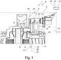
- Fig. 1 shows a partial view of a drive train 1 in a side view in section.
- the drive train 1 is part of a vehicle 2.
- the drive train 1 comprises a transmission housing 3 and a clutch unit 4 arranged therein with a positive coupling 5 as well as an actuation unit 6 for actuating the clutch 5 and a sensor 7 for determining the clutch status.
- the clutch 5 comprises a first clutch component 8 and a second clutch component 9, which are positively connected to one another when the clutch 5 is actuated.
- the actuation unit 6 comprises an electromagnetic actuator 10 with a piston 11, the piston 11 being displaced from an initial position 12 into an end position 13 in order to actuate the clutch 5.
- the piston 11 and the clutch 5 are arranged in a transmission fluid 14.
- a transmission of a torque via the clutch components 8, 9 should only take place after a fully engaged first state 15 (not shown here) of the clutch components 8, 9 has been established, for which the piston 11 is arranged in the end position 13.
- the sliding disk 26 is displaced by the piston 11 and the sensor disk 24 is displaced via the sliding disk 26.
- the sensor 7 detects the position of the sensor disk 24.
- the sensor disk 24 is connected to the second clutch component 11, so that a position of the piston 11 can be determined via the sensor 7.
- a position of the piston 11 or the second clutch component 9 can be determined via the sensor 7.
- the actuator 10 is actuated and the piston 11 is moved from the illustrated starting position 12 in the direction of the end position 13.
- a sensor measured value 16 is determined.
- the temperature 17 of the transmission fluid 14 is determined.
- an actual position 18 of the piston 11 is based on the Sensor measured value 16 and the determined temperature 17 determined.
- step e) starting from the determined actual position 18, the piston 11 is moved into the end position 13.
- the temperature 17 of the transmission fluid 14 is determined by measuring an electrical resistance 19 of the coil 27 of the actuator 10 or by measuring a first time interval between actuation of the actuator 10 according to step a) and the detection of an intermediate position 20 reached by the piston 11 by the sensor 7 determined.
- Parts of the coupling 5, for. B. the clutch components 8, 9, a sensor disk 24, a plate spring 25 designed as a return spring to return the second clutch component 9 and the piston 11, a sliding disk 26 and the piston 11 of the actuation unit 6 are acted upon by the transmission fluid 14 or are acted upon by the Transmission fluid 14 moved through.
- the viscosity of the transmission fluid 14 thus determines the switching time of the clutch 5.
- the sensor 7 generates temperature-dependent sensor measured values 16, so that the sensor 7 cannot (accurately) determine a position of the piston 11 independently of the temperature 17.
- the actuator 10 comprises a coil 27 to which an electric current is applied to displace the piston 11.
- the coil 27 of the actuator 10 is used as a temperature sensor. This makes use of the fact that an electrical resistance 19 of the coil 27 changes as a function of the temperature 17 (variant i. Of the method). This temperature dependence can, for. B. be stored in a map 21 in a control unit 30.
- the temperature 17 of the coil 27 corresponds at least largely to the temperature 17 of the transmission fluid 14.
- the temperature 17 of the transmission fluid 14 can be inferred from the temperature 17 of the coil 27 and thus on the one hand the (temperature-dependent) sensor measured value 16 determined in step b) with knowledge of the in step c) determined temperature 17 can be interpreted.
- the viscosity of the transmission fluid 14 can be determined via the temperature 17 determined in step c) and thus the speed of the piston 11 and clutch 5 components moved by the transmission fluid 14 can be determined.
- a second time interval can be determined after which the piston 11, starting from the actual position 18, reaches the end position 13.
- the piston 11 can be displaced further into the end position 13 from a precisely (more) determined actual position 18.
- the speed of the piston 11 can also be determined as a function of the determined temperature 17. Reaching the first state 15 can therefore be determined with increased accuracy, so that the release for the transmission of a torque via the clutch components 8, 9 can now take place more quickly.
- the temperature 17 of the transmission fluid 14 (step c)) is determined based on a first time interval between the actuation of the actuator 10 according to step a) and the detection of an intermediate position 20 reached by the piston 11 by the sensor 7. It is assumed here that the first time interval varies as a function of the viscosity of the transmission fluid 14 (and thus of the temperature 17 of the transmission fluid 14).
- the actual position 18 of the piston 11 is determined from a characteristic map 21 in step d). Correction factors for the sensor measured values 16 as a function of the temperature 17 are stored in the characteristics map 21. The sensor measured value 16 determined in step b) can thus be interpreted and the actual position 18 of the piston 11 can thus be determined with greater accuracy.
- a threshold value 22 is defined for the (temperature-dependent) sensor measured value 16 determined in step b), wherein if the sensor measured value 16 determined in step b) corresponds to the threshold value 22, it is assumed that the piston 11 moves from the starting position 12 to the intermediate position 20 is displaced, the coupling components 8, 9 in the intermediate position 20 of the piston 11 (just yet) not being positively connected to one another.
- the threshold value 22 is set in such a way that, on the one hand, a positive connection of the clutch components 8, 9 is not yet present in any case (especially at low temperature 17) and, on the other hand (e.g. at high temperature 17), a positive connection after the threshold value is exceeded 22 is immediately available.
- the temperature 17 determined (in step c) is used to determine a second time interval in which the piston 11, starting from the actual position 18, reaches the end position 13; the second time interval being taken into account for performing step e).
- the piston 11 can now be displaced further from the precisely (more) determined actual position 18 into the end position 13, the speed of the piston 11 likewise being able to be determined as a function of the determined temperature 17. Reaching the first state 15 can therefore be determined with increased accuracy, so that the release for the transmission of a torque via the clutch components 8, 9 now takes place more quickly.
- the second time interval is also determined from a (further) characteristic map 21.
- values of the second time interval are stored as a function of the determined temperature 17.
- the actuator 10 in order to measure the electrical resistance 19 of the actuator 10 (for example the coil 27 of the actuator 10), the actuator 10 is provided with a test signal 23, comprising an electrical current and an electrical Voltage, is applied, the piston 11 not being moved by the test signal 23.
- the temperature 17 of the transmission fluid 14 can thus be determined with sufficient accuracy from the measurement of the electrical resistance 19 (variant i. Of the method).
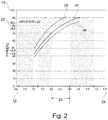
- Fig. 2 shows a diagram with several characteristic curves 28 of a sensor.
- the sensor measured value 16 measured in step b) is plotted here on the vertical axis.
- the position of the piston 11, that is to say the path 29, starting from an initial position 12, is plotted on the horizontal axis.
- the three characteristic curves 28 clarify the dependence of the sensor measured value 16 on the temperature 17.
- the middle characteristic curve 28 shows the characteristic curve 28 of the sensor 7 at an average temperature 17, e.g. B. at 20 degrees Celsius.
- a threshold value 22 is defined for the temperature-dependent sensor measured value 16 determined in step b), whereby if the sensor measured value 16 determined in step b) corresponds to the threshold value 22, it is assumed that the piston 11 moves from the starting position 12 to the intermediate position 20 is displaced, the coupling components 8, 9 in the intermediate position 20 of the piston 11 (just yet) not being positively connected to one another.
- the threshold value 22 is set in such a way that, on the one hand, a form-fitting connection of the clutch components 8, 9 is not yet present in any case (especially at low temperature 17, here i.e. lower characteristic curve 28) and on the other hand (e.g. at high temperature 17, here i.e. upper characteristic curve 28) a form-fitting connection of the clutch components 8, 9 is present immediately after the threshold value 22 is exceeded.
- the piston 11 When the threshold value 22 is reached, the piston 11 is therefore in an intermediate position 20 in which a form-fitting connection of the clutch components 8, 9 is not yet present in any case.
- a first time interval between actuation of the actuator 10 according to step a) (at this point in time the piston 11 is in the starting position 12) and the detection of an intermediate position 20 reached by the piston 11 by the sensor 7, the speed of the piston 11 can be determined during the movement through the transmission fluid 14.
- the viscosity of the transmission fluid 14 and thus its temperature 17 can be deduced from the speed of the piston 11.
- the corresponding characteristic curve 28 for the sensor 7 can be selected and the actual position 18 of the piston can be determined with sufficient accuracy .
- a second time interval can then be determined (taking into account the viscosity of the transmission fluid 14), after which the piston 11, starting from the actual position 18, reaches the end position 13.
Landscapes
- Engineering & Computer Science (AREA)
- General Engineering & Computer Science (AREA)
- Physics & Mathematics (AREA)
- Fluid Mechanics (AREA)
- Mechanical Engineering (AREA)
- Hydraulic Clutches, Magnetic Clutches, Fluid Clutches, And Fluid Joints (AREA)
Priority Applications (1)
| Application Number | Priority Date | Filing Date | Title |
|---|---|---|---|
| PL17709410T PL3589857T3 (pl) | 2017-03-03 | 2017-03-03 | Sposób i urządzenie do obsługi układu napędowego |
Applications Claiming Priority (1)
| Application Number | Priority Date | Filing Date | Title |
|---|---|---|---|
| PCT/EP2017/055089 WO2018157950A1 (de) | 2017-03-03 | 2017-03-03 | Verfahren und vorrichtung zum betrieb eines antriebsstranges |
Publications (2)
| Publication Number | Publication Date |
|---|---|
| EP3589857A1 EP3589857A1 (de) | 2020-01-08 |
| EP3589857B1 true EP3589857B1 (de) | 2021-02-24 |
Family
ID=58261652
Family Applications (1)
| Application Number | Title | Priority Date | Filing Date |
|---|---|---|---|
| EP17709410.9A Active EP3589857B1 (de) | 2017-03-03 | 2017-03-03 | Verfahren und vorrichtung zum betrieb eines antriebsstranges |
Country Status (6)
| Country | Link |
|---|---|
| US (1) | US10955015B2 (pl) |
| EP (1) | EP3589857B1 (pl) |
| JP (1) | JP6926220B2 (pl) |
| CN (1) | CN110337551B (pl) |
| PL (1) | PL3589857T3 (pl) |
| WO (1) | WO2018157950A1 (pl) |
Families Citing this family (6)
| Publication number | Priority date | Publication date | Assignee | Title |
|---|---|---|---|---|
| EP3978773B1 (en) * | 2020-10-02 | 2023-04-12 | Robert Bosch GmbH | Method for calibrating a coupling system of a mechanical transmission |
| EP3978775B1 (en) * | 2020-10-02 | 2023-12-06 | Robert Bosch GmbH | Method for calibrating a coupling system of a mechanical transmission |
| DE112021007741A5 (de) | 2021-05-31 | 2024-04-11 | Gkn Automotive Ltd. | Verfahren zum Betrieb eines Antriebsstranges und Antriebsstrang |
| FR3128165B1 (fr) | 2021-10-14 | 2023-09-08 | Valeo Embrayages | Système de propulsion de véhicule électrique ou hybride |
| CN115143209B (zh) * | 2022-05-26 | 2024-02-20 | 潍柴动力股份有限公司 | 车辆离合器自学习方法、装置、设备、介质及车辆 |
| JP2025166928A (ja) * | 2024-04-25 | 2025-11-07 | ジーケーエヌ オートモーティブ リミテッド | 駆動装置 |
Family Cites Families (16)
| Publication number | Priority date | Publication date | Assignee | Title |
|---|---|---|---|---|
| JPH0826909B2 (ja) | 1989-06-27 | 1996-03-21 | 三菱電機株式会社 | 車両用電磁クラッチの温度検出装置 |
| US6378682B1 (en) * | 1998-10-16 | 2002-04-30 | New Venture Gear, Inc. | Multi-function control valve for hydraulic coupling |
| JP2004208460A (ja) * | 2002-12-26 | 2004-07-22 | Tochigi Fuji Ind Co Ltd | 電磁駆動装置 |
| US7051856B2 (en) * | 2003-11-04 | 2006-05-30 | General Motors Corporation | Method and apparatus for applying and releasing a clutch |
| JP2008275057A (ja) * | 2007-04-27 | 2008-11-13 | Mitsubishi Heavy Ind Ltd | インチングバルブ構造 |
| GB2458498B (en) * | 2008-03-20 | 2012-02-08 | Ford Global Tech Llc | A method and apparatus for validating the output from a position sensor |
| DE102009043243A1 (de) | 2008-10-30 | 2010-05-06 | Luk Lamellen Und Kupplungsbau Beteiligungs Kg | Verfahren zum Betreiben eines Antriebsstranges und Antriebsstrang |
| CN104246262B (zh) * | 2012-04-16 | 2017-05-24 | 舍弗勒技术有限两合公司 | 用于液压地操纵离合器的致动系统 |
| WO2014067516A1 (de) * | 2012-10-31 | 2014-05-08 | Schaeffler Technologies AG & Co. KG | Verfahren zur betätigung einer reibungskupplung |
| US8965652B2 (en) * | 2013-06-13 | 2015-02-24 | GM Global Technology Operations LLC | Adaptive control of a flow control solenoid |
| JP6194666B2 (ja) * | 2013-07-18 | 2017-09-13 | 株式会社ジェイテクト | 駆動力伝達制御装置 |
| CN106029425B (zh) * | 2014-02-27 | 2018-08-28 | 日产自动车株式会社 | 4轮驱动车的离合器控制装置 |
| EP3112201B1 (en) * | 2014-02-27 | 2018-06-13 | Nissan Motor Co., Ltd. | Clutch control device for 4-wheel drive vehicle |
| US9688141B2 (en) * | 2014-02-27 | 2017-06-27 | Nissan Motor Co., Ltd. | Clutch control device for four-wheel drive vehicle |
| KR101500389B1 (ko) | 2014-03-19 | 2015-03-10 | 현대자동차 주식회사 | 하이브리드 차량의 유압지령 학습장치 및 방법 |
| US9593723B2 (en) * | 2014-10-06 | 2017-03-14 | Caterpillar Inc. | Disconnect clutch |
-
2017
- 2017-03-03 PL PL17709410T patent/PL3589857T3/pl unknown
- 2017-03-03 WO PCT/EP2017/055089 patent/WO2018157950A1/de not_active Ceased
- 2017-03-03 JP JP2019547623A patent/JP6926220B2/ja active Active
- 2017-03-03 US US16/489,713 patent/US10955015B2/en active Active
- 2017-03-03 CN CN201780087920.3A patent/CN110337551B/zh active Active
- 2017-03-03 EP EP17709410.9A patent/EP3589857B1/de active Active
Also Published As
| Publication number | Publication date |
|---|---|
| PL3589857T3 (pl) | 2021-09-06 |
| CN110337551A (zh) | 2019-10-15 |
| CN110337551B (zh) | 2020-11-17 |
| US10955015B2 (en) | 2021-03-23 |
| JP2020509314A (ja) | 2020-03-26 |
| WO2018157950A1 (de) | 2018-09-07 |
| JP6926220B2 (ja) | 2021-08-25 |
| US20200003265A1 (en) | 2020-01-02 |
| EP3589857A1 (de) | 2020-01-08 |
Similar Documents
| Publication | Publication Date | Title |
|---|---|---|
| EP3589857B1 (de) | Verfahren und vorrichtung zum betrieb eines antriebsstranges | |
| DE112013002007B4 (de) | Verfahren zur Ermittlung von Parametern einer zwischen einer geöffneten und einer geschlossenen Position betätigbaren Reibungskupplungseinrichtung | |
| WO2002101258A2 (de) | Kupplungsbetätigungsvorrichtung sowie verfahren zum ermitteln von kupplugsparametern | |
| DE19823089A1 (de) | Verfahren und Vorrichtung zur Steuerung einer Kupplung | |
| DE112013003917B4 (de) | Verfahren zur Ermittlung eines Tastpunkts einer Reibungskupplungseinrichtung | |
| DE102016211759B3 (de) | Verfahren zur Bestimmung einer Leckage in einem hydraulischen Kupplungssystem eines Hybridfahrzeuges | |
| DE102014211669A1 (de) | Verfahren zur Ermittlung einer Tastpunktänderung einer Hybridtrennkupplung eines Hybridfahrzeuges | |
| DE102011085751A1 (de) | Verfahren zur Ermittlung von Kupplungsreibwerten sowie Verfahren zur Ermittlung von Kupplungstastpunkten | |
| WO2013135449A1 (de) | Verfahren zur inbetriebnahme einer reibungskupplung | |
| EP2195558B1 (de) | Verfahren zur notsteuerung eines automatisierten schaltgetriebes | |
| EP2265838B1 (de) | VERFAHREN UND VORRICHTUNG ZUM SCHLIEßEN EINER KUPPLUNG | |
| EP1887244B1 (de) | Verfahren zur Überprüfung der Kupplungsposition einer mittels eines Aktors automatisiert betätigten Kupplung | |
| DE102016200689B4 (de) | Verfahren zur Ermittlung eines Tastpunktes einer Hybridtrennkupplung eines Hybridfahrzeuges | |
| DE102018104008A1 (de) | Verfahren zur Gangerkennung bei einem Handschaltgetriebe in Fahrzeugen mit einer Reibungskupplung | |
| DE102021122500A1 (de) | Verfahren zum Auskuppeln einer Kupplungsvorrichtung und elektrischer Antriebsstrang | |
| DE102015200981A1 (de) | Verfahren zum Kontrollieren einer von einer Reibungskupplungseinrichtung übertragenen mechanischen Leistung | |
| DE102016123952A1 (de) | Verfahren zum Betätigen einer Kupplung eines Hybridantriebsstranges sowie Antriebsstrang mit Kupplung | |
| EP1593870B1 (de) | Verfahren zum Erkennen eines Fehlers einer Betätigungseinrichtung | |
| DE102006045858A1 (de) | Verfahren zur Steuerung einer automatisierten Kupplung | |
| DE102016220456A1 (de) | Bestimmung eines Greifpunkts einer Kupplung | |
| WO2015039660A2 (de) | Modell zum simulieren einer reibkupplung | |
| DE102013207935A1 (de) | Prüfverfahren für ein sperrsynchronisiertes Schaltgetriebe | |
| WO2018196913A1 (de) | Verfahren zur adaption einer momentenkennlinie einer reibungskupplung | |
| DE102010063023A1 (de) | Vorrichtung zur Bestimmung eines Betriebzustandes eines formschlüssigen Schaltelementes | |
| DE102020118949A1 (de) | Überwachung eines Zustands eines Aktors in einem System zur variablen Ventilsteuerung eines Verbrennungsmotors |
Legal Events
| Date | Code | Title | Description |
|---|---|---|---|
| STAA | Information on the status of an ep patent application or granted ep patent |
Free format text: STATUS: UNKNOWN |
|
| STAA | Information on the status of an ep patent application or granted ep patent |
Free format text: STATUS: THE INTERNATIONAL PUBLICATION HAS BEEN MADE |
|
| PUAI | Public reference made under article 153(3) epc to a published international application that has entered the european phase |
Free format text: ORIGINAL CODE: 0009012 |
|
| STAA | Information on the status of an ep patent application or granted ep patent |
Free format text: STATUS: REQUEST FOR EXAMINATION WAS MADE |
|
| 17P | Request for examination filed |
Effective date: 20190905 |
|
| AK | Designated contracting states |
Kind code of ref document: A1 Designated state(s): AL AT BE BG CH CY CZ DE DK EE ES FI FR GB GR HR HU IE IS IT LI LT LU LV MC MK MT NL NO PL PT RO RS SE SI SK SM TR |
|
| AX | Request for extension of the european patent |
Extension state: BA ME |
|
| RAP1 | Party data changed (applicant data changed or rights of an application transferred) |
Owner name: GKN AUTOMOTIVE LTD. |
|
| DAV | Request for validation of the european patent (deleted) | ||
| DAX | Request for extension of the european patent (deleted) | ||
| GRAP | Despatch of communication of intention to grant a patent |
Free format text: ORIGINAL CODE: EPIDOSNIGR1 |
|
| STAA | Information on the status of an ep patent application or granted ep patent |
Free format text: STATUS: GRANT OF PATENT IS INTENDED |
|
| INTG | Intention to grant announced |
Effective date: 20200914 |
|
| GRAS | Grant fee paid |
Free format text: ORIGINAL CODE: EPIDOSNIGR3 |
|
| GRAA | (expected) grant |
Free format text: ORIGINAL CODE: 0009210 |
|
| STAA | Information on the status of an ep patent application or granted ep patent |
Free format text: STATUS: THE PATENT HAS BEEN GRANTED |
|
| AK | Designated contracting states |
Kind code of ref document: B1 Designated state(s): AL AT BE BG CH CY CZ DE DK EE ES FI FR GB GR HR HU IE IS IT LI LT LU LV MC MK MT NL NO PL PT RO RS SE SI SK SM TR |
|
| REG | Reference to a national code |
Ref country code: CH Ref legal event code: EP |
|
| REG | Reference to a national code |
Ref country code: AT Ref legal event code: REF Ref document number: 1364817 Country of ref document: AT Kind code of ref document: T Effective date: 20210315 |
|
| REG | Reference to a national code |
Ref country code: IE Ref legal event code: FG4D Free format text: LANGUAGE OF EP DOCUMENT: GERMAN |
|
| REG | Reference to a national code |
Ref country code: DE Ref legal event code: R096 Ref document number: 502017009462 Country of ref document: DE |
|
| REG | Reference to a national code |
Ref country code: LT Ref legal event code: MG9D |
|
| REG | Reference to a national code |
Ref country code: NL Ref legal event code: MP Effective date: 20210224 |
|
| PG25 | Lapsed in a contracting state [announced via postgrant information from national office to epo] |
Ref country code: LT Free format text: LAPSE BECAUSE OF FAILURE TO SUBMIT A TRANSLATION OF THE DESCRIPTION OR TO PAY THE FEE WITHIN THE PRESCRIBED TIME-LIMIT Effective date: 20210224 Ref country code: BG Free format text: LAPSE BECAUSE OF FAILURE TO SUBMIT A TRANSLATION OF THE DESCRIPTION OR TO PAY THE FEE WITHIN THE PRESCRIBED TIME-LIMIT Effective date: 20210524 Ref country code: GR Free format text: LAPSE BECAUSE OF FAILURE TO SUBMIT A TRANSLATION OF THE DESCRIPTION OR TO PAY THE FEE WITHIN THE PRESCRIBED TIME-LIMIT Effective date: 20210525 Ref country code: FI Free format text: LAPSE BECAUSE OF FAILURE TO SUBMIT A TRANSLATION OF THE DESCRIPTION OR TO PAY THE FEE WITHIN THE PRESCRIBED TIME-LIMIT Effective date: 20210224 Ref country code: HR Free format text: LAPSE BECAUSE OF FAILURE TO SUBMIT A TRANSLATION OF THE DESCRIPTION OR TO PAY THE FEE WITHIN THE PRESCRIBED TIME-LIMIT Effective date: 20210224 Ref country code: PT Free format text: LAPSE BECAUSE OF FAILURE TO SUBMIT A TRANSLATION OF THE DESCRIPTION OR TO PAY THE FEE WITHIN THE PRESCRIBED TIME-LIMIT Effective date: 20210624 Ref country code: NO Free format text: LAPSE BECAUSE OF FAILURE TO SUBMIT A TRANSLATION OF THE DESCRIPTION OR TO PAY THE FEE WITHIN THE PRESCRIBED TIME-LIMIT Effective date: 20210524 |
|
| PG25 | Lapsed in a contracting state [announced via postgrant information from national office to epo] |
Ref country code: LV Free format text: LAPSE BECAUSE OF FAILURE TO SUBMIT A TRANSLATION OF THE DESCRIPTION OR TO PAY THE FEE WITHIN THE PRESCRIBED TIME-LIMIT Effective date: 20210224 Ref country code: NL Free format text: LAPSE BECAUSE OF FAILURE TO SUBMIT A TRANSLATION OF THE DESCRIPTION OR TO PAY THE FEE WITHIN THE PRESCRIBED TIME-LIMIT Effective date: 20210224 Ref country code: RS Free format text: LAPSE BECAUSE OF FAILURE TO SUBMIT A TRANSLATION OF THE DESCRIPTION OR TO PAY THE FEE WITHIN THE PRESCRIBED TIME-LIMIT Effective date: 20210224 Ref country code: SE Free format text: LAPSE BECAUSE OF FAILURE TO SUBMIT A TRANSLATION OF THE DESCRIPTION OR TO PAY THE FEE WITHIN THE PRESCRIBED TIME-LIMIT Effective date: 20210224 |
|
| PG25 | Lapsed in a contracting state [announced via postgrant information from national office to epo] |
Ref country code: IS Free format text: LAPSE BECAUSE OF FAILURE TO SUBMIT A TRANSLATION OF THE DESCRIPTION OR TO PAY THE FEE WITHIN THE PRESCRIBED TIME-LIMIT Effective date: 20210624 |
|
| PG25 | Lapsed in a contracting state [announced via postgrant information from national office to epo] |
Ref country code: EE Free format text: LAPSE BECAUSE OF FAILURE TO SUBMIT A TRANSLATION OF THE DESCRIPTION OR TO PAY THE FEE WITHIN THE PRESCRIBED TIME-LIMIT Effective date: 20210224 Ref country code: CZ Free format text: LAPSE BECAUSE OF FAILURE TO SUBMIT A TRANSLATION OF THE DESCRIPTION OR TO PAY THE FEE WITHIN THE PRESCRIBED TIME-LIMIT Effective date: 20210224 Ref country code: SM Free format text: LAPSE BECAUSE OF FAILURE TO SUBMIT A TRANSLATION OF THE DESCRIPTION OR TO PAY THE FEE WITHIN THE PRESCRIBED TIME-LIMIT Effective date: 20210224 |
|
| REG | Reference to a national code |
Ref country code: CH Ref legal event code: PL |
|
| REG | Reference to a national code |
Ref country code: DE Ref legal event code: R097 Ref document number: 502017009462 Country of ref document: DE |
|
| PG25 | Lapsed in a contracting state [announced via postgrant information from national office to epo] |
Ref country code: MC Free format text: LAPSE BECAUSE OF FAILURE TO SUBMIT A TRANSLATION OF THE DESCRIPTION OR TO PAY THE FEE WITHIN THE PRESCRIBED TIME-LIMIT Effective date: 20210224 Ref country code: RO Free format text: LAPSE BECAUSE OF FAILURE TO SUBMIT A TRANSLATION OF THE DESCRIPTION OR TO PAY THE FEE WITHIN THE PRESCRIBED TIME-LIMIT Effective date: 20210224 Ref country code: DK Free format text: LAPSE BECAUSE OF FAILURE TO SUBMIT A TRANSLATION OF THE DESCRIPTION OR TO PAY THE FEE WITHIN THE PRESCRIBED TIME-LIMIT Effective date: 20210224 Ref country code: SK Free format text: LAPSE BECAUSE OF FAILURE TO SUBMIT A TRANSLATION OF THE DESCRIPTION OR TO PAY THE FEE WITHIN THE PRESCRIBED TIME-LIMIT Effective date: 20210224 |
|
| REG | Reference to a national code |
Ref country code: BE Ref legal event code: MM Effective date: 20210331 |
|
| PLBE | No opposition filed within time limit |
Free format text: ORIGINAL CODE: 0009261 |
|
| STAA | Information on the status of an ep patent application or granted ep patent |
Free format text: STATUS: NO OPPOSITION FILED WITHIN TIME LIMIT |
|
| GBPC | Gb: european patent ceased through non-payment of renewal fee |
Effective date: 20210524 |
|
| PG25 | Lapsed in a contracting state [announced via postgrant information from national office to epo] |
Ref country code: IE Free format text: LAPSE BECAUSE OF NON-PAYMENT OF DUE FEES Effective date: 20210303 Ref country code: LI Free format text: LAPSE BECAUSE OF NON-PAYMENT OF DUE FEES Effective date: 20210331 Ref country code: LU Free format text: LAPSE BECAUSE OF NON-PAYMENT OF DUE FEES Effective date: 20210303 Ref country code: AL Free format text: LAPSE BECAUSE OF FAILURE TO SUBMIT A TRANSLATION OF THE DESCRIPTION OR TO PAY THE FEE WITHIN THE PRESCRIBED TIME-LIMIT Effective date: 20210224 Ref country code: CH Free format text: LAPSE BECAUSE OF NON-PAYMENT OF DUE FEES Effective date: 20210331 Ref country code: ES Free format text: LAPSE BECAUSE OF FAILURE TO SUBMIT A TRANSLATION OF THE DESCRIPTION OR TO PAY THE FEE WITHIN THE PRESCRIBED TIME-LIMIT Effective date: 20210224 |
|
| 26N | No opposition filed |
Effective date: 20211125 |
|
| PG25 | Lapsed in a contracting state [announced via postgrant information from national office to epo] |
Ref country code: SI Free format text: LAPSE BECAUSE OF FAILURE TO SUBMIT A TRANSLATION OF THE DESCRIPTION OR TO PAY THE FEE WITHIN THE PRESCRIBED TIME-LIMIT Effective date: 20210224 |
|
| PG25 | Lapsed in a contracting state [announced via postgrant information from national office to epo] |
Ref country code: GB Free format text: LAPSE BECAUSE OF NON-PAYMENT OF DUE FEES Effective date: 20210524 |
|
| PG25 | Lapsed in a contracting state [announced via postgrant information from national office to epo] |
Ref country code: IS Free format text: LAPSE BECAUSE OF FAILURE TO SUBMIT A TRANSLATION OF THE DESCRIPTION OR TO PAY THE FEE WITHIN THE PRESCRIBED TIME-LIMIT Effective date: 20210624 |
|
| PG25 | Lapsed in a contracting state [announced via postgrant information from national office to epo] |
Ref country code: BE Free format text: LAPSE BECAUSE OF NON-PAYMENT OF DUE FEES Effective date: 20210331 |
|
| PG25 | Lapsed in a contracting state [announced via postgrant information from national office to epo] |
Ref country code: CY Free format text: LAPSE BECAUSE OF FAILURE TO SUBMIT A TRANSLATION OF THE DESCRIPTION OR TO PAY THE FEE WITHIN THE PRESCRIBED TIME-LIMIT Effective date: 20210224 |
|
| PG25 | Lapsed in a contracting state [announced via postgrant information from national office to epo] |
Ref country code: HU Free format text: LAPSE BECAUSE OF FAILURE TO SUBMIT A TRANSLATION OF THE DESCRIPTION OR TO PAY THE FEE WITHIN THE PRESCRIBED TIME-LIMIT; INVALID AB INITIO Effective date: 20170303 |
|
| PGFP | Annual fee paid to national office [announced via postgrant information from national office to epo] |
Ref country code: AT Payment date: 20240318 Year of fee payment: 8 |
|
| PG25 | Lapsed in a contracting state [announced via postgrant information from national office to epo] |
Ref country code: MK Free format text: LAPSE BECAUSE OF FAILURE TO SUBMIT A TRANSLATION OF THE DESCRIPTION OR TO PAY THE FEE WITHIN THE PRESCRIBED TIME-LIMIT Effective date: 20210224 |
|
| PGFP | Annual fee paid to national office [announced via postgrant information from national office to epo] |
Ref country code: PL Payment date: 20240221 Year of fee payment: 8 Ref country code: IT Payment date: 20240329 Year of fee payment: 8 Ref country code: FR Payment date: 20240319 Year of fee payment: 8 |
|
| PG25 | Lapsed in a contracting state [announced via postgrant information from national office to epo] |
Ref country code: MT Free format text: LAPSE BECAUSE OF FAILURE TO SUBMIT A TRANSLATION OF THE DESCRIPTION OR TO PAY THE FEE WITHIN THE PRESCRIBED TIME-LIMIT Effective date: 20210224 |
|
| PGFP | Annual fee paid to national office [announced via postgrant information from national office to epo] |
Ref country code: DE Payment date: 20250319 Year of fee payment: 9 |
|
| REG | Reference to a national code |
Ref country code: AT Ref legal event code: MM01 Ref document number: 1364817 Country of ref document: AT Kind code of ref document: T Effective date: 20250303 |
|
| PG25 | Lapsed in a contracting state [announced via postgrant information from national office to epo] |
Ref country code: TR Free format text: LAPSE BECAUSE OF FAILURE TO SUBMIT A TRANSLATION OF THE DESCRIPTION OR TO PAY THE FEE WITHIN THE PRESCRIBED TIME-LIMIT Effective date: 20210224 |
|
| PG25 | Lapsed in a contracting state [announced via postgrant information from national office to epo] |
Ref country code: AT Free format text: LAPSE BECAUSE OF NON-PAYMENT OF DUE FEES Effective date: 20250303 |
|
| PG25 | Lapsed in a contracting state [announced via postgrant information from national office to epo] |
Ref country code: IT Free format text: LAPSE BECAUSE OF NON-PAYMENT OF DUE FEES Effective date: 20250303 Ref country code: FR Free format text: LAPSE BECAUSE OF NON-PAYMENT OF DUE FEES Effective date: 20250331 |