EP3589433B1 - Verfahren zur sicherung einer selbstsichernden mutter an einem blech aus fortschrittlichem hochfestem stahl - Google Patents
Verfahren zur sicherung einer selbstsichernden mutter an einem blech aus fortschrittlichem hochfestem stahl Download PDFInfo
- Publication number
- EP3589433B1 EP3589433B1 EP18760741.1A EP18760741A EP3589433B1 EP 3589433 B1 EP3589433 B1 EP 3589433B1 EP 18760741 A EP18760741 A EP 18760741A EP 3589433 B1 EP3589433 B1 EP 3589433B1
- Authority
- EP
- European Patent Office
- Prior art keywords
- sheet
- ahss
- clinch
- nut
- joining
- Prior art date
- Legal status (The legal status is an assumption and is not a legal conclusion. Google has not performed a legal analysis and makes no representation as to the accuracy of the status listed.)
- Active
Links
Images


Classifications
-
- B—PERFORMING OPERATIONS; TRANSPORTING
- B21—MECHANICAL METAL-WORKING WITHOUT ESSENTIALLY REMOVING MATERIAL; PUNCHING METAL
- B21D—WORKING OR PROCESSING OF SHEET METAL OR METAL TUBES, RODS OR PROFILES WITHOUT ESSENTIALLY REMOVING MATERIAL; PUNCHING METAL
- B21D39/00—Application of procedures in order to connect objects or parts, e.g. coating with sheet metal otherwise than by plating; Tube expanders
- B21D39/03—Application of procedures in order to connect objects or parts, e.g. coating with sheet metal otherwise than by plating; Tube expanders of sheet metal otherwise than by folding
- B21D39/031—Joining superposed plates by locally deforming without slitting or piercing
-
- B—PERFORMING OPERATIONS; TRANSPORTING
- B21—MECHANICAL METAL-WORKING WITHOUT ESSENTIALLY REMOVING MATERIAL; PUNCHING METAL
- B21J—FORGING; HAMMERING; PRESSING METAL; RIVETING; FORGE FURNACES
- B21J15/00—Riveting
- B21J15/02—Riveting procedures
- B21J15/08—Riveting by applying heat, e.g. to the end parts of the rivets to enable heads to be formed
-
- B—PERFORMING OPERATIONS; TRANSPORTING
- B21—MECHANICAL METAL-WORKING WITHOUT ESSENTIALLY REMOVING MATERIAL; PUNCHING METAL
- B21J—FORGING; HAMMERING; PRESSING METAL; RIVETING; FORGE FURNACES
- B21J15/00—Riveting
- B21J15/10—Riveting machines
- B21J15/28—Control devices specially adapted to riveting machines not restricted to one of the preceding subgroups
-
- B—PERFORMING OPERATIONS; TRANSPORTING
- B23—MACHINE TOOLS; METAL-WORKING NOT OTHERWISE PROVIDED FOR
- B23K—SOLDERING OR UNSOLDERING; WELDING; CLADDING OR PLATING BY SOLDERING OR WELDING; CUTTING BY APPLYING HEAT LOCALLY, e.g. FLAME CUTTING; WORKING BY LASER BEAM
- B23K26/00—Working by laser beam, e.g. welding, cutting or boring
- B23K26/08—Devices involving relative movement between laser beam and workpiece
- B23K26/083—Devices involving movement of the workpiece in at least one axial direction
- B23K26/0853—Devices involving movement of the workpiece in at least in two axial directions, e.g. in a plane
-
- B—PERFORMING OPERATIONS; TRANSPORTING
- B23—MACHINE TOOLS; METAL-WORKING NOT OTHERWISE PROVIDED FOR
- B23P—METAL-WORKING NOT OTHERWISE PROVIDED FOR; COMBINED OPERATIONS; UNIVERSAL MACHINE TOOLS
- B23P19/00—Machines for simply fitting together or separating metal parts or objects, or metal and non-metal parts, whether or not involving some deformation; Tools or devices therefor so far as not provided for in other classes
- B23P19/04—Machines for simply fitting together or separating metal parts or objects, or metal and non-metal parts, whether or not involving some deformation; Tools or devices therefor so far as not provided for in other classes for assembling or disassembling parts
- B23P19/06—Screw or nut setting or loosening machines
- B23P19/062—Pierce nut setting machines
- B23P19/064—Deforming the support material only, e.g. the sheet or plate
-
- F—MECHANICAL ENGINEERING; LIGHTING; HEATING; WEAPONS; BLASTING
- F16—ENGINEERING ELEMENTS AND UNITS; GENERAL MEASURES FOR PRODUCING AND MAINTAINING EFFECTIVE FUNCTIONING OF MACHINES OR INSTALLATIONS; THERMAL INSULATION IN GENERAL
- F16B—DEVICES FOR FASTENING OR SECURING CONSTRUCTIONAL ELEMENTS OR MACHINE PARTS TOGETHER, e.g. NAILS, BOLTS, CIRCLIPS, CLAMPS, CLIPS OR WEDGES; JOINTS OR JOINTING
- F16B37/00—Nuts or like thread-engaging members
- F16B37/04—Devices for fastening nuts to surfaces, e.g. sheets, plates
- F16B37/06—Devices for fastening nuts to surfaces, e.g. sheets, plates by means of welding or riveting
- F16B37/062—Devices for fastening nuts to surfaces, e.g. sheets, plates by means of welding or riveting by means of riveting
- F16B37/068—Devices for fastening nuts to surfaces, e.g. sheets, plates by means of welding or riveting by means of riveting by deforming the material of the support, e.g. the sheet or plate
Definitions
- This invention relates to a method as claimed for securing a clinch nut to a sheet of advanced high strength.
- the invention provides an improved method for securing a clinch nut to a sheet of AHSS, according to claim 1.
- the indexing member is either moved in a rectilinear manner between the heating position and the joining position or pivotally moved between the heating position and the joining position.
- the temperature of the AHSS sheet is sensed at its work location from above or below the AHSS sheet.
- the controller operates a plurality of the joining assemblies spaced from each other; the controller also operates a parallel kinematic machine (PKM) including: a first support; a tripod having three extendable and retractable struts mounted and extending away from the first support in a converging manner toward each other; and a second support mounted by the three struts spaced from the first support to mount the nut ram that cooperates with the clinch die under the operation of the controller to provide the attachment of the clinch nut to the AHSS sheet; and wherein perpendicular rails mount the PKM for movement under its operation of the controller in horizontal directions that are perpendicular to each other to cooperate with the joining assemblies to provide attaching of pierce clinch nuts to the AHSS sheet at different locations.
- PKM parallel kinematic machine
- the joining assembly and the nut ram are operated between a floor and an upper beam of a framework mounted on the floor.
- the joining assembly is operated below the AHSS sheet and the nut ram is operated above the AHSS sheet.
- the controller operates a plurality of the joining assemblies mounted on the floor spaced from each other; and a nut ram assembly mounts a plurality of the nut rams and under the operation of the controller cooperates with the joining assemblies to simultaneously provide attaching of pierce clinch nuts to the AHSS sheet at different locations.
- one end of a C frame supports the joining assembly and another end of the C frame supports the nut ram that cooperates with the clinch die under the operation of the controller to provide attaching of a clinch nut to the AHSS sheet, and wherein a robot moves the C frame under operation of the controller to provide the attaching of the clinch nut to the AHSS sheet at different locations.
- FIG. 1 , 2 and 3 three different embodiments of apparatus 20 are illustrated for providing a method of the invention for providing an assembly 22 of a pierce clinch nut 24, having an extended pierce form 132 and a threaded hole 25 therethrough and is secured by a clinch interlock as is hereinafter described to a sheet of AHSS 26 as shown in Figure 4 .
- Both the apparatus for providing the method of the invention and the method of the invention will be described in an integrated manner to facilitate an understanding of different aspects of the method of the invention.
- the AHSS sheet 26 has a tensile strength of at least 700 mega Pascal or higher.
- AHSS has particular utility for use in vehicle body-in-white assembly of structural components such as pillars and roof headers.
- AHSS sheets are generally not workable using conventional mechanical joining methods.
- the embodiments of the apparatus 20 shown in Figures 1-3 are each disclosed as being within a light-safe work station 28 that can be controlled so no operation of laser heating that is involved can be performed unless human access thereof it prevented.
- the work stations 28 can be configured so human access thereto during the operation can be permitted as it is hereinafter more fully described.
- the embodiments of the apparatus 20 respectively shown in Figures 1 , 2 and 3 are each mounted on a horizontal support 30 such as a "floor”, a "factory floor”, a “pedestal” or a "floor pedestal” all of which will be covered in connection with reference numeral 30 for purposes of this application.
- FIG. 1 , 2 and 3 The different embodiments of the apparatus 20 respectively shown in Figures 1 , 2 and 3 are more specifically identified as 20a, 20b and 20c and may be operated singularly or in combination that will be discussed in providing the assembly 22 show in Figure 4 with one or more clinch nuts 24 secured to the AHSS sheet 26 so as to facilitate connection of another component to the AHSS sheet by use of a threaded fastener such as a threaded bolt, threaded stud or the like received by its threaded hole 25.
- a threaded fastener such as a threaded bolt, threaded stud or the like received by its threaded hole 25.
- Each of the work stations 28 shown in Figures 1-3 includes at least one joining assembly 32, a plurality of which joining assemblies are part of the embodiments 20a and 20b of Figures 1 and 2 , and only a single joining assembly with the embodiment of apparatus 20c shown in Figure 3 .
- Each of the embodiments of the apparatus includes a base 34 and an indexing member 36 mounted on the base for movement parallel to the AHSS sheet 26. The indexing member moves between a heating position where a heating opening 38 is located and a joining position where a clinch die 40 is spaced from each other along a direction parallel to the AHSS sheet 26.
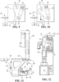
- An actuator 42 moves the indexing member 36 between the heating position shown in Figures 5, 7 and 9 where its heating opening 38 is aligned with a work location 44 of the AHSS sheet 26 and a joining position shown in Figures 6, 8 and 10 where a clinch die 40 located within the indexing member is aligned with the work location 44.
- a laser assembly 48 of each embodiment fires a laser beam 50 as illustrated in Figure 5 through the heating opening 38 of the indexing member 36 while in the heating position to provide heating of the AHSS sheet 26.
- Such heating makes the heated work location 44 of the AHSS sheet 26 more ductile to permit the piercing of the hole and attachment of the clinch nut to the AHSS sheet.
- Each embodiment of the apparatus 20 includes a nut ram 52 to which the pierce clinch nuts 24 are cyclically fed and which cooperates with the clinch die 40 by movement toward each other to attach each clinch nut to the AHSS sheet 26 thereby clinching it to the heated work location 44 of the AHSS sheet as shown in Figures 17-19 so that a threaded fastener as previously discussed can be connected to the AHSS sheet.
- Each embodiment of the apparatus 20 shown in Figures 1-3 includes a controller 54 that operates the joining assembly 32 and the nut ram 52 and any other necessary components of the apparatus to provide the attachment of clinch nuts 24 to the AHSS sheet 26 as the assembly 22 shown in Figure 4 .
- each embodiment of the disclosed apparatus is provided with its joining assembly 32 including an enclosure 56 defining a light-safe chamber 58 partially defined by the base 34.
- the laser assembly 48 fires the laser beam 50 through an opening 60 in the base 34 as well as through the heating opening 38 in the indexing member 36 while the indexing member 36 is in the heating position to provide the heating of the work location 44 of the AHSS sheet 26.
- the mounting of AHSS sheet to the index member 36 on the base 34 as shown in Figure 5 is light-safe to prevent excessive radiation emissions from escaping from the light-safe chamber.
- a detector assembly 62 is operated by the controller 54 to only permit operation of the laser assembly 48 when the AHSS sheet 26 is in light-safe contact with the indexing member 36 around its heating opening 38. As such, operators can then have safe access to the work station 28 for any necessary operational, repair or maintenance function, even when the apparatus is performing the clinch nut attachment as described, without any operator being subjected to any harmful scattered radiation from the laser beam.
- each of the embodiments of the joining assembly 32 has its detection assembly 62 including a source 64 for providing pressurized gas to the light-safe chamber 58 of the joining assembly as well as including sensors 66 and 68 between which a detector 70 is located to detect a predetermined gas movement between the sensors which is indicative of a lack of light-safe contact with the indexing member around its heating opening 38 with the AHSS sheet 26 in order to provide a signal to the controller 54 that prevents the laser assembly 48 from the laser beam 50 when the laser is activated.
- the laser is supplied from a laser generator 72 to a collimator 74 that fires the laser beam 50 through the base opening 60 and the heating opening 38 of the indexing member to the work location 44 of the AHSS sheet 26 as previously described.
- the clinch nuts attached by the apparatus and method are disclosed as pierce clinch nuts 24 that pierce through and form an interlock connection with the AHSS sheet 26 as is hereinafter more fully described, with the laser heating providing the AHSS sheet 26 with sufficient ductility to permit the piercing of the hole and attachment of the clinch nut.
- the joining assembly 32 includes a slideway 76 that supports the indexing member 36 on the base 34 for rectilinear movement, in a light-safe manner as discussed above, between its heating position shown in Figure 7 and its joining position shown in Figure 8 under the operation of the actuator 42 which may be of any suitable type such as an air cylinder or a solenoid directly connected or through a linkage to the indexing member.
- the joining assembly 32 may have its indexing member 36 supported on the base 34 by a pivotal connection 78 for pivotal movement, in a light-safe manner as discussed above, between its heating position of Figure 9 and its joining position of Figure 10 .
- the indexing member may include a die insert 80 that allows the clinch die 40 to be replaced due to wear or for switching the types of clinch nut utilized for the construction of the clinch dies needed for the production of jobs being performed.
- the joining assembly includes a temperature sensor 82 for sensing the temperature of the work location 44 of the AHSS sheet 26 from either top or bottom side of the AHSS sheet through the heating opening 38 of the indexing member 36.
- This temperature sensing may be used to determine the extent of heating for performing any production job being executed.
- the temperature sensor 82 it is also possible for the temperature sensor 82 to sense the temperature of work location 44 from above on its side that faces away from the indexing member of the joining assembly 32. With either embodiment, it is also possible for the sensed temperature to control the extent of laser heating by operation of the controller 54 if such control is warranted.
- the embodiment of apparatus 20a includes a plurality of the joining assemblies 32 mounted on the horizontal support 30 provided by the factory floor.
- Laser heating provided by the apparatus 20a heats the AHSS sheet 26 to provide the mechanical joining of the clinch nut to the AHSS sheet as is hereinafter more fully described.
- the laser generator 72 through a beam splitter feeding fiber optic cables 86 feeds the laser to the laser collimators (identified as 74 in Figure 5 ) to selectively provide heating at a plurality of work locations respectively aligned with the plurality of joining assemblies 32.
- Apparatus 20a shown in Figure 1 also includes a parallel kinematic machine (referred to as a PKM) 88 that is mounted by a schematically illustrated carriage supported riser 90 on horizontal rails 92 and 94 that extend in perpendicular directions to each other on a framework 96 that is itself supported on the factory floor 30 and has an upper beam 97 on which the support is provided.
- a parallel kinematic machine referred to as a PKM
- the PKM 88 supports the nut ram 52 that cooperates with the clinch die 40 ( Figures 17-19 ) of the joining assembly 32 to provide the joining by piercing a hole and clinching the clinch nut to the AHSS sheet, and the nut ram 52 is movable in horizontal directions perpendicular to each other along the rails 92 and 94 to different work locations while the operation of struts of the PKM by extension and retraction moves the nut ram 52 provides the clinch nut attachments. Furthermore, the nut ram 52 cyclically feeds pierce cinch nuts 24 for the joining operation.
- a feeder 98 shown on the riser 90 cyclically feeds the pierce clinch nuts 24 to the nut ram 52 and may be of any conventional type such as the feeders disclosed by the United States patent 7,100,260 of Mark A. Savoy et al. entitled PROGRAMMABLE APPARATUS AND METHOD FOR VEHICLE BODY PANEL AND CLINCH NUT ATTACHMENT or by the United States patent 7,398,896 of Phillip J. I. Morgan entitled VEHICLE BODY SHEET METAL CLINCH NUT FEEDER.
- This pierce clinch nut feeding is shown in Figures 15 and 16 held between spring fingers 100 and against a positioning stop 101 of the nut ram 52.
- the riser 90 of PKM 88 connects a first support 102 thereof to the carriage 104 that is supported for movement in perpendicular directions by the perpendicular rails 92 and 94 to a selected position under operation of the controller 54.
- Extendable and retractable struts 106 of the PKM 88 project from the first support 102 to a second support 108 to provide a tripod 110 arrangement with the second support mounting the nut ram 52 for rotation and angular positioning that permits the operation at any required orientation in cooperation with the joining assembly 32 as previously described.
- the struts 106 may be extendable and retractable in any suitable manner such as disclosed by United States patent application Publication No. 2016/0263641, published on September 15, 2016 by Mark A.
- the struts 106 may each be embodied by a roller screw having: an upper end pivotally connected to the first support 102 of the PKM and a lower end pivotally connected to the second support 108, an elongated screw, a nut including a planet carrier and a plurality of threaded rollers rotatable on the planet carrier and meshed with the screw such that relative rotation between the screw and the nut changes the length of the strut as disclosed in the referenced application.
- the embodiment of the apparatus 20b includes at least one joining assembly 32 mounted on the factory floor 30. With a single joining assembly 32, the AHSS sheet 26 is positionally indexed to provide clinch nut connection at different locations. It is also possible for this embodiment like the embodiment of Figure 1 to have a plurality of the joining assemblies 32 mounted on the factory floor 30 and fed by the laser generator 72 through the cables 86. These joining assemblies 32 are operated by the controller 54 in cooperation with a nut ram assembly 110 including a platen 111 that supports one or a plurality of the nut rams 52, each of which that has a nut feeder 98.
- the platen 111 is movable vertically by one or a plurality of operators 112 supported on framework 96 at its upper beam 97 for vertical to provide the piercing and clinching for attachment of the clinch nuts as shown in Figures 17-19 .
- this embodiment will perform one clinch nut piercing at a time with a single nut ram 52.
- the AHSS sheet 26 can then be horizontally indexed as needed to perform the pierce clinch nut connection at other locations.
- this embodiment can sequentially pierce a hole and clinch the clinch nut 24 to the AHSS sheet 26 at each joining assembly.
- each nut ram 52 of this embodiment can be angularly operated on platen 111 as needed by cams to control their angularity of operation relative to the vertical movement provided by the operator 112.
- the apparatus 20c includes a C frame 114 having one end 116 supporting the joining assembly 32 where in a laser beam is provided to heat the AHSS sheet 26, and the C frame 114 has another end 118 that supports the nut ram 52. More specifically, a housing 120 of the C frame 114 supports the laser collimator 74 and, as shown best in Figure 13 , has its laser beam 50 projecting downwardly from the collimator toward a first mirror 122 within the light-safe chamber 58 defined by the housing.
- That first mirror 122 reflects the laser beam 50 at a 90 degree angle horizontally toward a second mirror 124 for reflection 90 degrees upwardly toward the indexing member 36 which functions generally the same as the previously described embodiment of Figures 9 and 10 by pivoting between its heating position and its joining position.
- Extension and retraction of the piston connecting rod 126 of actuator 42 in this embodiment pivots the indexing member 36 about pivotal connection 78 to move between the heating position and the joining position.
- each embodiment begins as shown in Figure 17 with clinch die 40 located in the indexing member 36 while the indexing member is in the joining position shown in Figure 7 . While in this position, the chamber 58 remains light-safe since the clinch die 40 mounted in the indexing member 36 is covering the opening 60. The indexing member then moves to the heating position so that the AHSS sheet can be heated by the laser beam. Actuation of the nut ram 52 as shown in Figure 17 brings the piercing form 132 of the clinch nut 24 into contact with the heated AHSS sheet 26. Continuing downward motion of the nut ram 52 moves pierce form 132 into the AHSS sheet to create a pierced hole as shown in Figure 18 .
- the pierced slug is discarded through an opening in the clinch die 40.
- the heated AHSS sheet 26 area surrounding the opening of the clinch die 40 starts to flow into an undercut 129 of the clinch nut 24 as shown in Figure 18 .
- the AHSS sheet 26 continues to flow into the undercut so as to create an interlock 133 and completely fill the area of the undercut 129 and securely attach the clinch nut 24 to the AHSS sheet 26 as shown in Figures 4 and 19 .
- the ram 52 is moved upward to its start position where after the cycle repeats itself.
- the piercing form 132 may be of a configuration i.e. round, square, oblong or contoured.
- the sheet 26 of AHSS to which the clinch nut 24 is attached will normally have a thickness of 0.7 to 2 millimeters and will be heated to an approximate temperature of 500° to 825° C.
- the heating time depends on the thickness but will normally be about 0.5 to 1.5 seconds and the indexing time will be about 0.1 to 0.3 of a second, the time to perform the attachment of the clinch will be about 1.2 to 2.2 seconds and the laser will be of any type of laser that is able to accomplish these functions as stated.
- the laser utilized may be a fiber laser or a diode laser. Also, during the laser heating and mechanical joining, any suitable but not shown clamping or the like may be used to position the AHSS sheet 26 for the operation.
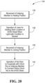
- the controller 54 shown and described above in connection with Figures 1-3 is configured to provide the operation shown by the flow chart 134 of Figure 20 . As described above, this operation begins by step 136 as the indexing member is moved to the heating position and continues with step 138 as the laser provides the light-safe heating of the work location of the AHSS sheet. The following movement of the indexing member to the joining position as shown by step 140 is then followed by the nut ram and die operation of step 142 to connect the clinch nut to the sheet of AHSS.
Landscapes
- Engineering & Computer Science (AREA)
- Mechanical Engineering (AREA)
- General Engineering & Computer Science (AREA)
- Physics & Mathematics (AREA)
- Optics & Photonics (AREA)
- Plasma & Fusion (AREA)
- Automatic Assembly (AREA)
- Connection Of Plates (AREA)
- Insertion Pins And Rivets (AREA)
- Lining Or Joining Of Plastics Or The Like (AREA)
Claims (10)
- Verfahren zum Befestigen einer Clinchmutter (24) an einer AHSS-Platte (26) mit den Schritten:Positionieren eines AHSS-Blechs (26) neben einer Verbindungsbaugruppe (32), die ein parallel zu dem AHSS-Blech bewegliches Indexierungselement (36) mit einer Heizöffnung (38) und einer Clinchmatrize (40) aufweist, die in einer zu dem AHSS-Blech parallelen Richtung voneinander beabstandet sind;Abfeuern eines Laserstrahls (50) durch die Heizöffnung (38) des Indexierungselements (36) an einer Heizposition desselben, um eine Bearbeitungsstelle des AHSS-Blechs zu erhitzen;Bewegen des Indexierungselements (36) parallel zu dem AHSS-Blech in eine Verbindungsposition, in der seine Clinchmatrize (40) mit der Bearbeitungsstelle des AHSS-Blechs fluchtet ist; undVerwenden einer Steuerung (54) zum Betreiben eines Mutternstempels (52), dem Clinchmuttern, von denen jede eine Gewindeöffnung aufweist, zugeführt werden, um mit der Clinchmatrize zu fluchten, wenn sich das Indexierungselement (36) in der Verbindungsposition befindet, um eine Clinchmutter an dem AHSS-Blech an seiner erhitzten Bearbeitungsstelle zu befestigen, so dass ein mit Gewinde versehenes Befestigungselement mit der Clinchmutter verbunden werden kann; wobei der Laserstrahl (50) aus dem Inneren einer lichtdichten Kammer (58) durch eine Öffnung (60) in der Kammer (58) und dann durch die Heizöffnung (38) des Indexierungselements (36) abgefeuert wird, während es sich in der Heizposition befindet, um die Erhitzung der Bearbeitungsstelle des AHSS-Blechs zu bewirken, und wobei das Abfeuern des Laserstrahls von der Steuerung (54) nur dann zugelassen wird, wenn das Vorhandensein des AHSS-Blechs festgestellt wird, das die Heizöffnung (38) des Indexierungselements (36) um seine Heizöffnung (38) herum mit lichtdichtem Kontakt verschließt.
- Verfahren zum Befestigen einer Clinchmutter an einem AHSS-Blech nach Anspruch 1, bei dem ein Druckgasstrom durch die lichtdichte Kammer (58) erfasst wird, um festzustellen, ob das AHSS-Blech das Indexierungselement (36) um seine Heizöffnung (38) herum in einem lichtdichten Ausmaß berührt, um den Betrieb des Laserstrahls durch die Steuerung zu steuern.
- Verfahren zum Befestigen einer Clinchmutter an einem AHSS-Blech nach Anspruch 1, bei dem dem Mutternstempel (52) Durchstanz-Clinchmuttern (24) zugeführt werden.
- Verfahren zum Befestigen einer Clinchmutter an einem AHSS-Blech nach Anspruch 1, bei dem das Indexierungselement (36) entweder geradlinig zwischen der Heizposition und der Fügeposition oder schwenkend zwischen der Heizposition und der Fügeposition bewegt wird.
- Verfahren zum Befestigen einer Einpressmutter an einem AHSS-Blech nach Anspruch 1, bei dem die Temperatur des AHSS-Blechs an seiner Arbeitsstelle von oberhalb oder unterhalb des AHSS-Blechs gemessen wird.
- Verfahren zum Befestigen einer Clinchmutter an einem AHSS-Blech nach Anspruch 1, bei dem: die Steuerung (54) eine Mehrzahl der voneinander beabstandeten Verbindungsbaugruppen (32) betätigt; die Steuerung außerdem eine Parallelkinematik (PKM; 88) betätigt, die umfasst: eine erste Halterung (102); ein Dreibein (110) mit drei ausfahrbaren und einfahrbaren Streben (106), die an der ersten Halterung befestigt sind und sich von dieser weg in einer zueinander konvergierenden Weise erstrecken; und eine zweite Halterung (108), die durch die drei Streben im Abstand von der ersten Halterung gehalten ist, um den Mutternstempel (52) zu tragen, der mit der Clinchmatrize (40) unter Kontrolle der Steuerung zusammenwirkt, um das Befestigen der Clinchmutter an dem AHSS-Blech zu bewerkstelligen; und wobei senkrechte Schienen die PKM (88) für eine Bewegung unter Kontrolle der Steuerung (54) in zueinander senkrechten horizontalen Richtungen halten, um mit den Verbindungsbaugruppen (32) zusammenzuwirken, um die Befestigung von Durchstanz-Clinchmuttern an dem AHSS-Blech an verschiedenen Stellen zu ermöglichen.
- Verfahren zum Befestigen einer Clinchmutter an einer AHSS-Platte nach Anspruch 1, bei dem die Verbindungsbaugruppe (32) und der Mutternstempel (52) zwischen einem Boden (60) und einem oberen Balken (97) eines auf dem Boden montierten Gerüsts (96) betrieben werden.
- Verfahren zum Befestigen einer Clinchmutter an einem AHSS-Blech nach Anspruch 5, bei dem die Verbindungsbaugruppe (32) unterhalb des AHSS-Blechs und der Mutternstempel (52) oberhalb des AHSS-Blechs betätigt wird.
- Verfahren zum Befestigen einer Clinchmutter an einer AHSS-Platte nach Anspruch 1, bei dem die Steuerung (54) eine Mehrzahl von Verbindungsbaugruppen (32) betätigt, die im Abstand voneinander auf dem Boden (30) montiert sind; und eine Mutterstempelbaugruppe eine Mehrzahl von Mutterstempeln (52) trägt und unter Kontrolle der Steuerung mit den Verbindungsbaugruppen (32) zusammenwirkt, um eine gleichzeitige Befestigung von Clinchmuttern an der AHSS-Platte an verschiedenen Stellen zu ermöglichen.
- Verfahren zum Befestigen einer Clinchmutter an einem AHSS-Blech nach Anspruch 1, bei dem ein Ende eines C-Rahmens (114) die Verbindungsbaugruppe (32) trägt und ein anderes Ende des C-Rahmens (114) den Mutternstempel (52) trägt, der mit der Clinchmatrize (40) unter Kontrolle der Steuerung (54) zusammenwirkt, um das Anbringen einer Clinchmutter an dem AHSS-Blech zu ermöglichen, und bei dem ein Roboter (130) den C-Rahmen (114) unter Kontrolle der Steuerung (54) bewegt, um das Befestigen der Clinchmutter an dem AHSS-Blech an verschiedenen Stellen zu ermöglichen.
Applications Claiming Priority (2)
| Application Number | Priority Date | Filing Date | Title |
|---|---|---|---|
| US201762466489P | 2017-03-03 | 2017-03-03 | |
| PCT/US2018/020654 WO2018160959A1 (en) | 2017-03-03 | 2018-03-02 | Apparatus and method for securing a clinch nut to a sheet of advanced high strength steel and resultant assembly |
Publications (3)
| Publication Number | Publication Date |
|---|---|
| EP3589433A1 EP3589433A1 (de) | 2020-01-08 |
| EP3589433A4 EP3589433A4 (de) | 2021-01-27 |
| EP3589433B1 true EP3589433B1 (de) | 2025-05-07 |
Family
ID=63357124
Family Applications (1)
| Application Number | Title | Priority Date | Filing Date |
|---|---|---|---|
| EP18760741.1A Active EP3589433B1 (de) | 2017-03-03 | 2018-03-02 | Verfahren zur sicherung einer selbstsichernden mutter an einem blech aus fortschrittlichem hochfestem stahl |
Country Status (9)
| Country | Link |
|---|---|
| US (2) | US12128473B2 (de) |
| EP (1) | EP3589433B1 (de) |
| JP (1) | JP7094294B2 (de) |
| KR (1) | KR102579210B1 (de) |
| CN (1) | CN110382133B (de) |
| BR (1) | BR112019018170B1 (de) |
| CA (1) | CA3052671A1 (de) |
| ES (1) | ES3031933T3 (de) |
| WO (1) | WO2018160959A1 (de) |
Families Citing this family (9)
| Publication number | Priority date | Publication date | Assignee | Title |
|---|---|---|---|---|
| EP3589433B1 (de) | 2017-03-03 | 2025-05-07 | Utica Enterprises, Inc. | Verfahren zur sicherung einer selbstsichernden mutter an einem blech aus fortschrittlichem hochfestem stahl |
| US20230041416A1 (en) * | 2021-08-03 | 2023-02-09 | Utica Enterprises, Inc. | Mechanically joining advanced high strength steel |
| US12097548B2 (en) | 2021-08-09 | 2024-09-24 | Kuka Systems North America Llc | Apparatus and methods for forming an attachment pad in high strength steel materials |
| DE102021121087A1 (de) * | 2021-08-13 | 2023-02-16 | Tox Pressotechnik Gmbh & Co. Kg | Fügewerkzeugeinheit |
| DE102021121084A1 (de) * | 2021-08-13 | 2023-02-16 | Alpha Laser Gmbh | Fügewerkzeugeinheit, Werkzeugzange und Fügevorgang |
| DE102021121086A1 (de) * | 2021-08-13 | 2023-02-16 | Alpha Laser Gmbh | Fügewerkzeugeinheit und Werkzeugzange |
| DE102021121090A1 (de) * | 2021-08-13 | 2023-02-16 | Tox Pressotechnik Gmbh & Co. Kg | Fügewerkzeugeinheit |
| US12297856B2 (en) * | 2023-03-13 | 2025-05-13 | The Boeing Company | Nut plate grippers, end effectors that include nut plate grippers, robots that include end effectors, installation systems that include robots, and related methods |
| CN117000848B (zh) * | 2023-08-28 | 2024-07-05 | 苏州丹卡精密机械有限公司 | 一种具有缓冲防护功能的冲压模具 |
Citations (2)
| Publication number | Priority date | Publication date | Assignee | Title |
|---|---|---|---|---|
| US6417490B1 (en) * | 1997-11-17 | 2002-07-09 | Technische Universitaet Dresden | Method and device for thermally supporting mechanical joints |
| US7740436B2 (en) * | 2006-03-22 | 2010-06-22 | R B & W Manufacturing Llc | Clinch nut |
Family Cites Families (69)
| Publication number | Priority date | Publication date | Assignee | Title |
|---|---|---|---|---|
| US3213914A (en) | 1961-11-06 | 1965-10-26 | Illinois Tool Works | Self-piercing nut with attaching groove |
| US4237363A (en) | 1977-02-04 | 1980-12-02 | Lemelson Jerome H | Beam welding apparatus and method |
| US4564986A (en) | 1982-10-25 | 1986-01-21 | Illinois Tool Works Inc. | Apparatus for securement of clinch nut to carrier material |
| JPS62105736U (de) | 1985-12-23 | 1987-07-06 | ||
| JPS62179882A (ja) | 1986-02-05 | 1987-08-07 | Aisan Ind Co Ltd | レ−ザ−ビ−ムによる加熱方法 |
| JPH05255895A (ja) | 1992-03-10 | 1993-10-05 | Tokyo Multi Fastener Kk | ナット付き板金部品の製造方法並びに該方法の実施に使用するナット及びボルト・ナット・アッセンブリ |
| GB9226517D0 (en) | 1992-12-19 | 1993-02-10 | Henrob Ltd | Improvements in or relating to sefl-piercing riveting |
| KR100480466B1 (ko) | 1995-04-18 | 2005-06-28 | 필립모리스 프로덕츠 인코포레이티드 | 금속팩키지의제조방법 |
| US5882159A (en) | 1996-08-16 | 1999-03-16 | Profil Verbindungstechnik, Gmbh & Co. | Element, method of attaching the element to a plate-like component, component assembly and die button |
| DE19630488C2 (de) | 1996-07-26 | 1999-07-08 | Boellhoff Gmbh | Verfahren und Vorrichtung zum Fügen durch Umformen |
| DE19714129A1 (de) | 1997-04-05 | 1998-10-15 | Eckold Vorrichtung | Fügeverfahren und -vorrichtung |
| DE19800035A1 (de) | 1998-01-02 | 1999-07-08 | Volkswagen Ag | Verfahren zum Fügen von mindestens zwei Fügepartnern |
| US6725521B1 (en) | 1998-11-17 | 2004-04-27 | Henrob Limited | Fastening of sheet material |
| US6446478B1 (en) * | 1999-07-29 | 2002-09-10 | Progressive Tool & Industries Co. | Two-stage hemming machine with movable dies |
| US6439819B2 (en) * | 2000-06-06 | 2002-08-27 | Pem Management, Inc. | Progressively-formed clinch nut |
| DE20013526U1 (de) | 2000-08-05 | 2000-12-07 | Avdel Verbindungselemente GmbH, 30851 Langenhagen | Vorrichtung zum Verbinden von Blechen durch Stanznieten oder Durchsetzfügen |
| US6769595B2 (en) | 2000-12-20 | 2004-08-03 | Alcoa Inc. | Friction plunge riveting |
| DE10119018A1 (de) * | 2001-04-18 | 2002-10-24 | Emhart Llc Newark | Positionier- und/oder Montagehilfe sowie dementsprechendes Verfahren |
| US6684479B2 (en) | 2001-08-22 | 2004-02-03 | General Motors Corporation | Method and apparatus for clinching metal sheets |
| US6732420B2 (en) | 2002-03-08 | 2004-05-11 | General Motors Corporation | Method for riveting metal members therewith |
| US6694597B2 (en) | 2002-03-08 | 2004-02-24 | General Motors Corporation | Method for riveting metal members |
| AU2003301588A1 (en) | 2002-10-23 | 2004-05-13 | Fabristeel Products, Inc. | Self-attaching female fastener element and method of attachment |
| US6836948B2 (en) | 2003-02-05 | 2005-01-04 | General Motors Corporation | Method of joining a sheet metal part to a metal tube |
| SE525668C2 (sv) * | 2003-10-02 | 2005-03-29 | Parallel Kinematics Machines S | Led till ett lagrat ställdon lagrat kring ett wobbelorgan |
| US7032296B2 (en) * | 2003-11-21 | 2006-04-25 | Newfrey Llc | Self-piercing fastening system |
| US7267736B2 (en) | 2003-12-18 | 2007-09-11 | General Motors Corporation | Method of joining dissimilar materials |
| JP4150927B2 (ja) | 2004-05-31 | 2008-09-17 | トヨタ自動車株式会社 | ロール鍛造方法 |
| JP2006007266A (ja) | 2004-06-25 | 2006-01-12 | Nissan Motor Co Ltd | リベットを用いた接合方法 |
| JP2006043769A (ja) | 2004-07-05 | 2006-02-16 | Nissan Motor Co Ltd | セルフピアスリベットによる接合方法およびセルフピアスリベット接合装置 |
| CN100584509C (zh) | 2004-07-05 | 2010-01-27 | 株式会社大桥技研 | 压入接合用螺母、压入接合结构及压入接合方法 |
| DE102004062896B4 (de) | 2004-11-12 | 2006-09-07 | Fraunhofer-Gesellschaft zur Förderung der angewandten Forschung e.V. | Vorrichtung und Verfahren zum formschlüssigen Verbinden von Werkstücken |
| KR100743857B1 (ko) | 2005-07-14 | 2007-07-30 | 진인태 | 금속판 소성유동 압출점접합장치 및 압출점접합방법 |
| US8931990B2 (en) | 2006-04-25 | 2015-01-13 | Stromsholmen Ab | Pierce nut and use thereof |
| GB0609580D0 (en) | 2006-05-13 | 2006-06-21 | Henrob Ltd | Self-piercing riveting |
| US8234770B2 (en) * | 2006-05-31 | 2012-08-07 | Cast Crc Limited | Method and apparatus for joining metals using self-piercing rivets with preheating |
| US20080085368A1 (en) * | 2006-10-10 | 2008-04-10 | Gauthier Ben M | Method and Apparatus for Coating a Substrate |
| MX2009011698A (es) | 2007-05-02 | 2009-11-10 | Corus Staal Bv | Metodo para galvanizacion en caliente de material de ahss o uhss en tira, y este material. |
| US8608420B2 (en) | 2007-08-24 | 2013-12-17 | Whitesell International Corporation | Self-attaching nut |
| US20100310404A1 (en) * | 2007-12-06 | 2010-12-09 | Ulf Ackelid | Apparataus and method for producing a three-dimensional object |
| CN101469733A (zh) | 2007-12-25 | 2009-07-01 | 上海仪表厂有限责任公司 | 一种齿花压铆螺母及其铆接方法 |
| GB0813883D0 (en) | 2008-07-30 | 2008-09-03 | Henrob Ltd | Joining apparatus and method |
| US8434215B2 (en) * | 2008-08-05 | 2013-05-07 | Newfrey Llc | Self-piercing rivet setting machine |
| CN201275576Y (zh) | 2008-09-16 | 2009-07-22 | 陈莹霜 | 拉链头半自动四点铆压机 |
| DE102008056278A1 (de) | 2008-10-25 | 2010-04-29 | Kjellberg Finsterwalde Plasma Und Maschinen Gmbh | System zur thermischen Bearbeitung von Werkstücken |
| US8365376B2 (en) * | 2008-11-18 | 2013-02-05 | The Boeing Company | Rivet installation system |
| DE102010020666B4 (de) * | 2010-05-17 | 2020-04-16 | Tox Pressotechnik Gmbh & Co. Kg | Matrize und Werkzeug für ein Nietwerkzeug |
| JP5300027B2 (ja) | 2010-11-22 | 2013-09-25 | 有限会社新城製作所 | ピアスナットの固着方法 |
| CN102003448A (zh) | 2010-11-24 | 2011-04-06 | 苏州工业园区新凯精密五金有限公司 | 一种四方压铆螺母 |
| JP5626025B2 (ja) | 2011-03-02 | 2014-11-19 | 新日鐵住金株式会社 | 溶接部の遅れ破壊特性並びに静的強度特性に優れた自動車用構造部材、および、その製造方法 |
| US9259774B2 (en) | 2011-05-03 | 2016-02-16 | GM Global Technology Operations LLC | Clinching method and tool for performing the same |
| US8545157B2 (en) | 2011-06-10 | 2013-10-01 | Ford Global Technologies, Llc | Metal members and assemblies that have reinforced punched holes and method of forming the holes |
| DE102011051636A1 (de) * | 2011-07-07 | 2013-01-10 | Jenoptik Automatisierungstechnik Gmbh | Vorrichtung zum Fügen von Werkstücken |
| DE102012202330B4 (de) | 2012-02-16 | 2017-08-17 | Trumpf Laser Gmbh | Laserbearbeitungsvorrichtung mit einem relativ zu einer Spannpratze beweglichen Laserbearbeitungskopf |
| CN102672062B (zh) * | 2012-05-25 | 2015-02-11 | 吉林大学 | 激光加热无铆钉铆接装置 |
| CN103658416B (zh) * | 2012-09-26 | 2016-06-08 | 山东科技大学 | 一种用于自冲铆接的激光辅助加热装置 |
| JP6132515B2 (ja) | 2012-11-05 | 2017-05-24 | 株式会社吉野工作所 | ナット付きジョイント部材の製造方法 |
| KR101543244B1 (ko) | 2013-12-31 | 2015-08-10 | 주식회사 성우하이텍 | 리벳 공급장치 및 이를 포함하는 셀프 피어싱 리벳 시스템 |
| JP6687537B2 (ja) | 2014-01-16 | 2020-04-22 | アトラス コプコ アイエイエス ユーケー リミテッド | リベッティング方法 |
| JP6009004B2 (ja) * | 2015-01-20 | 2016-10-19 | 株式会社神戸製鋼所 | 異材接合用鍛造リベット及び異材接合方法 |
| WO2016205541A1 (en) | 2015-06-16 | 2016-12-22 | The Regents Of The University Of Michigan | Fastener and method for joining dissimilar materials |
| CN107614147B (zh) | 2015-07-01 | 2019-12-13 | 日本制铁株式会社 | 机械接合装置以及机械接合方法 |
| CN107614146B (zh) | 2015-07-01 | 2019-03-12 | 新日铁住金株式会社 | 机械接合装置以及机械接合方法 |
| JP6899392B2 (ja) * | 2016-02-03 | 2021-07-07 | ユーティカ エンタープライゼズ,インコーポレイテッド | 先進高強度鋼を機械的に接合するための装置及び方法 |
| US10161435B2 (en) * | 2016-02-15 | 2018-12-25 | Whitesell Formed Components, Inc. | Self-attaching fastener and panel assembly, and method of attaching |
| CN205977920U (zh) | 2016-06-28 | 2017-02-22 | 广州汽车集团股份有限公司 | 主定位结构 |
| CN205977992U (zh) * | 2016-07-29 | 2017-02-22 | 奇瑞新能源汽车技术有限公司 | 电动汽车全铝白车身用压铆螺母结构 |
| KR20180077492A (ko) | 2016-12-29 | 2018-07-09 | 현대자동차주식회사 | 레이저 국부 연화 열처리를 통한 초고장력강과 비강철소재의 접합방법 |
| EP3589433B1 (de) | 2017-03-03 | 2025-05-07 | Utica Enterprises, Inc. | Verfahren zur sicherung einer selbstsichernden mutter an einem blech aus fortschrittlichem hochfestem stahl |
| WO2020093143A1 (en) | 2018-11-05 | 2020-05-14 | Magna International Inc. | Localized resistance annealing process |
-
2018
- 2018-03-02 EP EP18760741.1A patent/EP3589433B1/de active Active
- 2018-03-02 JP JP2019543302A patent/JP7094294B2/ja active Active
- 2018-03-02 BR BR112019018170-9A patent/BR112019018170B1/pt active IP Right Grant
- 2018-03-02 WO PCT/US2018/020654 patent/WO2018160959A1/en not_active Ceased
- 2018-03-02 CA CA3052671A patent/CA3052671A1/en active Pending
- 2018-03-02 ES ES18760741T patent/ES3031933T3/es active Active
- 2018-03-02 US US15/910,599 patent/US12128473B2/en active Active
- 2018-03-02 KR KR1020197026688A patent/KR102579210B1/ko active Active
- 2018-03-02 CN CN201880015728.8A patent/CN110382133B/zh active Active
-
2023
- 2023-07-24 US US18/357,480 patent/US20240017319A1/en active Pending
Patent Citations (2)
| Publication number | Priority date | Publication date | Assignee | Title |
|---|---|---|---|---|
| US6417490B1 (en) * | 1997-11-17 | 2002-07-09 | Technische Universitaet Dresden | Method and device for thermally supporting mechanical joints |
| US7740436B2 (en) * | 2006-03-22 | 2010-06-22 | R B & W Manufacturing Llc | Clinch nut |
Also Published As
| Publication number | Publication date |
|---|---|
| KR20200003783A (ko) | 2020-01-10 |
| EP3589433A1 (de) | 2020-01-08 |
| US20240017319A1 (en) | 2024-01-18 |
| CA3052671A1 (en) | 2018-09-07 |
| US20180250734A1 (en) | 2018-09-06 |
| BR112019018170B1 (pt) | 2023-10-31 |
| JP7094294B2 (ja) | 2022-07-01 |
| WO2018160959A1 (en) | 2018-09-07 |
| JP2020508901A (ja) | 2020-03-26 |
| US12128473B2 (en) | 2024-10-29 |
| BR112019018170A2 (pt) | 2020-04-07 |
| ES3031933T3 (en) | 2025-07-14 |
| EP3589433A4 (de) | 2021-01-27 |
| CN110382133B (zh) | 2022-01-21 |
| KR102579210B1 (ko) | 2023-09-15 |
| CN110382133A (zh) | 2019-10-25 |
Similar Documents
| Publication | Publication Date | Title |
|---|---|---|
| US20240017319A1 (en) | Apparatus and method for securing a clinch nut to a sheet of advanced high strength steel and resultant assembly | |
| US11260447B2 (en) | Apparatus and method for mechanically joining advanced high strength steel | |
| JP2019505390A5 (de) | ||
| US20060230609A1 (en) | System and method for programmable pogo self-piercing riveting | |
| EP2722125B1 (de) | Projektionsschweißzange zum Befestigen eines Werkzeuges, wie beispielsweise einer Buchse, auf einer Oberfläche eines Blechelements, und Schweißanlage damit | |
| KR20150079289A (ko) | 리벳 공급장치 및 이를 포함하는 셀프 피어싱 리벳 시스템 | |
| WO2025051885A1 (en) | Self-pierce riveting tool and method for setting a self-piercing type rivet | |
| KR100527310B1 (ko) | 수동 점용접 및 자동 연속 점용접이 가능한 자동차용 강판의 점용접 장치 | |
| US11938532B2 (en) | Apparatus and method for automated application of rivets | |
| JP6439580B2 (ja) | 自動車のフード組付方法およびフード組付装置 | |
| US7521647B2 (en) | Joining device | |
| EP4458490A1 (de) | Verfahren zur herstellung einer nietverbindung | |
| US7398896B2 (en) | Vehicle body sheet metal clinch nut feeder | |
| CN115056162B (zh) | 一种铸铝件半自动辅助装配装置 | |
| CN218050004U (zh) | 一种用于加工汽车纵梁的定位组件 | |
| JPH0347750Y2 (de) | ||
| CN114889149A (zh) | 一种自动打钉装置 | |
| KR200147619Y1 (ko) | 검사기능이 부착된 부품 용접장치 | |
| Mangus et al. | G2000 nine axis flexibility to fasten 180 degree fuselage assemblies |
Legal Events
| Date | Code | Title | Description |
|---|---|---|---|
| STAA | Information on the status of an ep patent application or granted ep patent |
Free format text: STATUS: THE INTERNATIONAL PUBLICATION HAS BEEN MADE |
|
| PUAI | Public reference made under article 153(3) epc to a published international application that has entered the european phase |
Free format text: ORIGINAL CODE: 0009012 |
|
| STAA | Information on the status of an ep patent application or granted ep patent |
Free format text: STATUS: REQUEST FOR EXAMINATION WAS MADE |
|
| 17P | Request for examination filed |
Effective date: 20190918 |
|
| AK | Designated contracting states |
Kind code of ref document: A1 Designated state(s): AL AT BE BG CH CY CZ DE DK EE ES FI FR GB GR HR HU IE IS IT LI LT LU LV MC MK MT NL NO PL PT RO RS SE SI SK SM TR |
|
| AX | Request for extension of the european patent |
Extension state: BA ME |
|
| DAV | Request for validation of the european patent (deleted) | ||
| DAX | Request for extension of the european patent (deleted) | ||
| A4 | Supplementary search report drawn up and despatched |
Effective date: 20210112 |
|
| RIC1 | Information provided on ipc code assigned before grant |
Ipc: B21D 53/00 20060101AFI20201221BHEP |
|
| STAA | Information on the status of an ep patent application or granted ep patent |
Free format text: STATUS: EXAMINATION IS IN PROGRESS |
|
| 17Q | First examination report despatched |
Effective date: 20230310 |
|
| P01 | Opt-out of the competence of the unified patent court (upc) registered |
Effective date: 20231204 |
|
| GRAP | Despatch of communication of intention to grant a patent |
Free format text: ORIGINAL CODE: EPIDOSNIGR1 |
|
| STAA | Information on the status of an ep patent application or granted ep patent |
Free format text: STATUS: GRANT OF PATENT IS INTENDED |
|
| INTG | Intention to grant announced |
Effective date: 20241008 |
|
| GRAS | Grant fee paid |
Free format text: ORIGINAL CODE: EPIDOSNIGR3 |
|
| GRAA | (expected) grant |
Free format text: ORIGINAL CODE: 0009210 |
|
| STAA | Information on the status of an ep patent application or granted ep patent |
Free format text: STATUS: THE PATENT HAS BEEN GRANTED |
|
| AK | Designated contracting states |
Kind code of ref document: B1 Designated state(s): AL AT BE BG CH CY CZ DE DK EE ES FI FR GB GR HR HU IE IS IT LI LT LU LV MC MK MT NL NO PL PT RO RS SE SI SK SM TR |
|
| REG | Reference to a national code |
Ref country code: GB Ref legal event code: FG4D |
|
| REG | Reference to a national code |
Ref country code: CH Ref legal event code: EP |
|
| REG | Reference to a national code |
Ref country code: DE Ref legal event code: R096 Ref document number: 602018081732 Country of ref document: DE |
|
| REG | Reference to a national code |
Ref country code: IE Ref legal event code: FG4D |
|
| REG | Reference to a national code |
Ref country code: ES Ref legal event code: FG2A Ref document number: 3031933 Country of ref document: ES Kind code of ref document: T3 Effective date: 20250714 |
|
| REG | Reference to a national code |
Ref country code: NL Ref legal event code: MP Effective date: 20250507 |
|
| PG25 | Lapsed in a contracting state [announced via postgrant information from national office to epo] |
Ref country code: PT Free format text: LAPSE BECAUSE OF FAILURE TO SUBMIT A TRANSLATION OF THE DESCRIPTION OR TO PAY THE FEE WITHIN THE PRESCRIBED TIME-LIMIT Effective date: 20250908 Ref country code: FI Free format text: LAPSE BECAUSE OF FAILURE TO SUBMIT A TRANSLATION OF THE DESCRIPTION OR TO PAY THE FEE WITHIN THE PRESCRIBED TIME-LIMIT Effective date: 20250507 |
|
| REG | Reference to a national code |
Ref country code: LT Ref legal event code: MG9D |
|
| PG25 | Lapsed in a contracting state [announced via postgrant information from national office to epo] |
Ref country code: NO Free format text: LAPSE BECAUSE OF FAILURE TO SUBMIT A TRANSLATION OF THE DESCRIPTION OR TO PAY THE FEE WITHIN THE PRESCRIBED TIME-LIMIT Effective date: 20250807 Ref country code: GR Free format text: LAPSE BECAUSE OF FAILURE TO SUBMIT A TRANSLATION OF THE DESCRIPTION OR TO PAY THE FEE WITHIN THE PRESCRIBED TIME-LIMIT Effective date: 20250808 |
|
| PG25 | Lapsed in a contracting state [announced via postgrant information from national office to epo] |
Ref country code: PL Free format text: LAPSE BECAUSE OF FAILURE TO SUBMIT A TRANSLATION OF THE DESCRIPTION OR TO PAY THE FEE WITHIN THE PRESCRIBED TIME-LIMIT Effective date: 20250507 Ref country code: NL Free format text: LAPSE BECAUSE OF FAILURE TO SUBMIT A TRANSLATION OF THE DESCRIPTION OR TO PAY THE FEE WITHIN THE PRESCRIBED TIME-LIMIT Effective date: 20250507 |
|
| REG | Reference to a national code |
Ref country code: AT Ref legal event code: MK05 Ref document number: 1791930 Country of ref document: AT Kind code of ref document: T Effective date: 20250507 |
|
| PG25 | Lapsed in a contracting state [announced via postgrant information from national office to epo] |
Ref country code: BG Free format text: LAPSE BECAUSE OF FAILURE TO SUBMIT A TRANSLATION OF THE DESCRIPTION OR TO PAY THE FEE WITHIN THE PRESCRIBED TIME-LIMIT Effective date: 20250507 |
|
| PG25 | Lapsed in a contracting state [announced via postgrant information from national office to epo] |
Ref country code: HR Free format text: LAPSE BECAUSE OF FAILURE TO SUBMIT A TRANSLATION OF THE DESCRIPTION OR TO PAY THE FEE WITHIN THE PRESCRIBED TIME-LIMIT Effective date: 20250507 |
|
| PG25 | Lapsed in a contracting state [announced via postgrant information from national office to epo] |
Ref country code: AT Free format text: LAPSE BECAUSE OF FAILURE TO SUBMIT A TRANSLATION OF THE DESCRIPTION OR TO PAY THE FEE WITHIN THE PRESCRIBED TIME-LIMIT Effective date: 20250507 |
|
| PG25 | Lapsed in a contracting state [announced via postgrant information from national office to epo] |
Ref country code: RS Free format text: LAPSE BECAUSE OF FAILURE TO SUBMIT A TRANSLATION OF THE DESCRIPTION OR TO PAY THE FEE WITHIN THE PRESCRIBED TIME-LIMIT Effective date: 20250807 |
|
| PG25 | Lapsed in a contracting state [announced via postgrant information from national office to epo] |
Ref country code: IS Free format text: LAPSE BECAUSE OF FAILURE TO SUBMIT A TRANSLATION OF THE DESCRIPTION OR TO PAY THE FEE WITHIN THE PRESCRIBED TIME-LIMIT Effective date: 20250907 |
|
| PG25 | Lapsed in a contracting state [announced via postgrant information from national office to epo] |
Ref country code: LV Free format text: LAPSE BECAUSE OF FAILURE TO SUBMIT A TRANSLATION OF THE DESCRIPTION OR TO PAY THE FEE WITHIN THE PRESCRIBED TIME-LIMIT Effective date: 20250507 |
|
| PG25 | Lapsed in a contracting state [announced via postgrant information from national office to epo] |
Ref country code: DK Free format text: LAPSE BECAUSE OF FAILURE TO SUBMIT A TRANSLATION OF THE DESCRIPTION OR TO PAY THE FEE WITHIN THE PRESCRIBED TIME-LIMIT Effective date: 20250507 Ref country code: SM Free format text: LAPSE BECAUSE OF FAILURE TO SUBMIT A TRANSLATION OF THE DESCRIPTION OR TO PAY THE FEE WITHIN THE PRESCRIBED TIME-LIMIT Effective date: 20250507 |
|
| PG25 | Lapsed in a contracting state [announced via postgrant information from national office to epo] |
Ref country code: CZ Free format text: LAPSE BECAUSE OF FAILURE TO SUBMIT A TRANSLATION OF THE DESCRIPTION OR TO PAY THE FEE WITHIN THE PRESCRIBED TIME-LIMIT Effective date: 20250507 |
|
| PG25 | Lapsed in a contracting state [announced via postgrant information from national office to epo] |
Ref country code: EE Free format text: LAPSE BECAUSE OF FAILURE TO SUBMIT A TRANSLATION OF THE DESCRIPTION OR TO PAY THE FEE WITHIN THE PRESCRIBED TIME-LIMIT Effective date: 20250507 |
|
| PG25 | Lapsed in a contracting state [announced via postgrant information from national office to epo] |
Ref country code: RO Free format text: LAPSE BECAUSE OF FAILURE TO SUBMIT A TRANSLATION OF THE DESCRIPTION OR TO PAY THE FEE WITHIN THE PRESCRIBED TIME-LIMIT Effective date: 20250507 Ref country code: SK Free format text: LAPSE BECAUSE OF FAILURE TO SUBMIT A TRANSLATION OF THE DESCRIPTION OR TO PAY THE FEE WITHIN THE PRESCRIBED TIME-LIMIT Effective date: 20250507 |
|
| PG25 | Lapsed in a contracting state [announced via postgrant information from national office to epo] |
Ref country code: IT Free format text: LAPSE BECAUSE OF FAILURE TO SUBMIT A TRANSLATION OF THE DESCRIPTION OR TO PAY THE FEE WITHIN THE PRESCRIBED TIME-LIMIT Effective date: 20250507 |