EP3589221B1 - Vorrichtung zum schneiden von gewebe - Google Patents
Vorrichtung zum schneiden von gewebe Download PDFInfo
- Publication number
- EP3589221B1 EP3589221B1 EP18708123.7A EP18708123A EP3589221B1 EP 3589221 B1 EP3589221 B1 EP 3589221B1 EP 18708123 A EP18708123 A EP 18708123A EP 3589221 B1 EP3589221 B1 EP 3589221B1
- Authority
- EP
- European Patent Office
- Prior art keywords
- thread
- members
- tissue
- pulling
- contact
- Prior art date
- Legal status (The legal status is an assumption and is not a legal conclusion. Google has not performed a legal analysis and makes no representation as to the accuracy of the status listed.)
- Active
Links
Images


Classifications
-
- A—HUMAN NECESSITIES
- A61—MEDICAL OR VETERINARY SCIENCE; HYGIENE
- A61B—DIAGNOSIS; SURGERY; IDENTIFICATION
- A61B17/00—Surgical instruments, devices or methods
- A61B17/32—Surgical cutting instruments
- A61B17/3205—Excision instruments
- A61B17/32056—Surgical snare instruments
-
- A—HUMAN NECESSITIES
- A61—MEDICAL OR VETERINARY SCIENCE; HYGIENE
- A61B—DIAGNOSIS; SURGERY; IDENTIFICATION
- A61B17/00—Surgical instruments, devices or methods
- A61B17/04—Surgical instruments, devices or methods for suturing wounds; Holders or packages for needles or suture materials
- A61B17/06—Needles ; Sutures; Needle-suture combinations; Holders or packages for needles or suture materials
- A61B17/06166—Sutures
-
- A—HUMAN NECESSITIES
- A61—MEDICAL OR VETERINARY SCIENCE; HYGIENE
- A61B—DIAGNOSIS; SURGERY; IDENTIFICATION
- A61B17/00—Surgical instruments, devices or methods
- A61B17/11—Surgical instruments, devices or methods for performing anastomosis; Buttons for anastomosis
- A61B17/1114—Surgical instruments, devices or methods for performing anastomosis; Buttons for anastomosis of the digestive tract, e.g. bowels or oesophagus
-
- A—HUMAN NECESSITIES
- A61—MEDICAL OR VETERINARY SCIENCE; HYGIENE
- A61B—DIAGNOSIS; SURGERY; IDENTIFICATION
- A61B17/00—Surgical instruments, devices or methods
- A61B17/32—Surgical cutting instruments
- A61B17/3209—Incision instruments
-
- F—MECHANICAL ENGINEERING; LIGHTING; HEATING; WEAPONS; BLASTING
- F16—ENGINEERING ELEMENTS AND UNITS; GENERAL MEASURES FOR PRODUCING AND MAINTAINING EFFECTIVE FUNCTIONING OF MACHINES OR INSTALLATIONS; THERMAL INSULATION IN GENERAL
- F16H—GEARING
- F16H7/00—Gearings for conveying rotary motion by endless flexible members
- F16H7/08—Means for varying tension of belts, ropes or chains
-
- A—HUMAN NECESSITIES
- A61—MEDICAL OR VETERINARY SCIENCE; HYGIENE
- A61B—DIAGNOSIS; SURGERY; IDENTIFICATION
- A61B17/00—Surgical instruments, devices or methods
- A61B2017/00831—Material properties
- A61B2017/00867—Material properties shape memory effect
-
- A—HUMAN NECESSITIES
- A61—MEDICAL OR VETERINARY SCIENCE; HYGIENE
- A61B—DIAGNOSIS; SURGERY; IDENTIFICATION
- A61B17/00—Surgical instruments, devices or methods
- A61B2017/00831—Material properties
- A61B2017/00867—Material properties shape memory effect
- A61B2017/00871—Material properties shape memory effect polymeric
-
- A—HUMAN NECESSITIES
- A61—MEDICAL OR VETERINARY SCIENCE; HYGIENE
- A61B—DIAGNOSIS; SURGERY; IDENTIFICATION
- A61B17/00—Surgical instruments, devices or methods
- A61B2017/00831—Material properties
- A61B2017/00876—Material properties magnetic
-
- A—HUMAN NECESSITIES
- A61—MEDICAL OR VETERINARY SCIENCE; HYGIENE
- A61B—DIAGNOSIS; SURGERY; IDENTIFICATION
- A61B17/00—Surgical instruments, devices or methods
- A61B17/04—Surgical instruments, devices or methods for suturing wounds; Holders or packages for needles or suture materials
- A61B2017/0496—Surgical instruments, devices or methods for suturing wounds; Holders or packages for needles or suture materials for tensioning sutures
-
- A—HUMAN NECESSITIES
- A61—MEDICAL OR VETERINARY SCIENCE; HYGIENE
- A61B—DIAGNOSIS; SURGERY; IDENTIFICATION
- A61B17/00—Surgical instruments, devices or methods
- A61B17/04—Surgical instruments, devices or methods for suturing wounds; Holders or packages for needles or suture materials
- A61B17/06—Needles ; Sutures; Needle-suture combinations; Holders or packages for needles or suture materials
- A61B17/06166—Sutures
- A61B2017/0618—Sutures elastic, e.g. stretchable
-
- A—HUMAN NECESSITIES
- A61—MEDICAL OR VETERINARY SCIENCE; HYGIENE
- A61B—DIAGNOSIS; SURGERY; IDENTIFICATION
- A61B17/00—Surgical instruments, devices or methods
- A61B17/11—Surgical instruments, devices or methods for performing anastomosis; Buttons for anastomosis
- A61B17/1114—Surgical instruments, devices or methods for performing anastomosis; Buttons for anastomosis of the digestive tract, e.g. bowels or oesophagus
- A61B2017/1117—Surgical instruments, devices or methods for performing anastomosis; Buttons for anastomosis of the digestive tract, e.g. bowels or oesophagus adapted for discharge after necrotisation, e.g. by evacuation, expulsion or excretion
-
- A—HUMAN NECESSITIES
- A61—MEDICAL OR VETERINARY SCIENCE; HYGIENE
- A61B—DIAGNOSIS; SURGERY; IDENTIFICATION
- A61B17/00—Surgical instruments, devices or methods
- A61B17/11—Surgical instruments, devices or methods for performing anastomosis; Buttons for anastomosis
- A61B2017/1139—Side-to-side connections, e.g. shunt or X-connections
-
- A—HUMAN NECESSITIES
- A61—MEDICAL OR VETERINARY SCIENCE; HYGIENE
- A61B—DIAGNOSIS; SURGERY; IDENTIFICATION
- A61B17/00—Surgical instruments, devices or methods
- A61B17/32—Surgical cutting instruments
- A61B2017/32006—Surgical cutting instruments with a cutting strip, band or chain, e.g. like a chainsaw
-
- A—HUMAN NECESSITIES
- A61—MEDICAL OR VETERINARY SCIENCE; HYGIENE
- A61B—DIAGNOSIS; SURGERY; IDENTIFICATION
- A61B17/00—Surgical instruments, devices or methods
- A61B17/32—Surgical cutting instruments
- A61B17/3209—Incision instruments
- A61B2017/32096—Incision instruments for slowly cutting through tissue, e.g. stent like temporary implants having sharp edges
-
- F—MECHANICAL ENGINEERING; LIGHTING; HEATING; WEAPONS; BLASTING
- F16—ENGINEERING ELEMENTS AND UNITS; GENERAL MEASURES FOR PRODUCING AND MAINTAINING EFFECTIVE FUNCTIONING OF MACHINES OR INSTALLATIONS; THERMAL INSULATION IN GENERAL
- F16H—GEARING
- F16H7/00—Gearings for conveying rotary motion by endless flexible members
- F16H7/08—Means for varying tension of belts, ropes or chains
- F16H2007/0802—Actuators for final output members
- F16H2007/081—Torsion springs
Definitions
- the present invention is related to assemblies for creating pressure necrosis of wall portions of internal cavities of a human or animal body, and possibly creating compression anastomosis of adjacent wall portions.
- diverticulum can occur in various body cavities, such as though not limited to the gastrointestinal tract (oesophagus, intestine, colon), the bladder and the heart.
- fluids or solid substances such as food present in the cavity can get trapped in the pouch (diverticulum) and remain stagnant for a prolonged period, eventually leading to infection.
- fluid or solid substances get blocked, and cannot pursue their natural course.
- Current treatment techniques involve endoscopic stapling of the diverticulum.
- US 2008/0188766 A1 describes implantable devices and instruments for treatment of obesity. Particularly, it shows an anchor including connectors that are configured so that their length or lengths is/are adjustable.
- US 2007/0093861 A1 describes an implantable device for restricting a cross-sectional area of a cavity formed by a stomach wall. It includes a member that has a first end connected with respect to a first portion of the stomach wall and an opposing second end connected with respect to a second portion of the stomach wall. The member has shape memory properties and is adapted to move the first end towards the second end.
- WO 2014/055193 A1 shows an apparatus that provides an anastomosis, coupling two hollow organs.
- the apparatus includes a first elongate body, a second elongate body, and a tether assembly.
- Each elongate body defines a respective opening and has at least one respective magnetic member.
- the magnetic member of the second elongate body attracts the magnetic member of the first elongate body.
- the tether assembly is operable to draw the first and second elongate bodies toward each other to bring the magnetic member of the first elongate body within a magnetic field of the magnetic member of the second elongate body.
- the device or assembly comprises a first member comprising a first material, a second member comprising a second material and a thread connected to the first member and to the second member.
- the first and second materials show magnetic attraction between one another.
- the device or assembly comprises further means for pulling the thread.
- the means for pulling the thread comprises a thread winding system configured to maintain tension in the thread between the first member and the second member.
- One or both the first and the second member comprises a housing, wherein the thread winding system is enclosed in the housing.
- the means for pulling the thread comprises a third member connected to the thread, wherein the second member is slidingly connected to the thread and interposed between the first and the third member along the thread.
- the device or assembly enables to perform methods as described herein.
- the means for pulling the thread allow for applying an additional force/pressure on the tissue by the thread, so that tissue becomes necrotic due to prolonged action of the pressure and can be sheared more effectively, and with increased safety, e.g. reducing risk of infections.
- Tissue shearing can be provided alone or in combination with other operations, such as though not limited to pressure necrosis and compression anastomosis.
- a method is described for creating pressure necrosis of a tissue wall between a pouch and an adjacent cavity in a human or animal body, and possibly anastomosis of surrounding tissue.
- the pouch advantageously opens into the cavity.
- the tissue wall hence comprises a periphery forming an edge of the opening between the pouch and the cavity.
- diverticulum such as though not limited to Zenker's diverticulum, and epiphrenic diverticulum and present methods advantageously allow for treating these.
- a first member is placed into the pouch, such that the first member is adjacent the tissue wall.
- a second member is placed in the cavity and proximate the first member.
- the first member and the second member comprise materials which magnetically attract one another.
- the first member and the second member are placed such that there is magnetic attraction between the first member and the second member through the wall. Due to the magnetic attraction force, the first member and the second member compress a portion of the wall overlapping the first member and the second member for a prolonged time period, which creates pressure necrosis of that overlapping wall portion.
- a thread extends between the first member and the second member and is connected thereto, and extends over the edge to form a loop over the wall.
- the tissue compressed between the first member and the second member becomes necrotic, and collapses, thereby forming an opening through the wall.
- a continuing pressure can be applied by the thread on the tissue, to create a local necrosis of the tissue, which aids in tissue shearing by the thread, and renders it more effective and safer.
- the first member and the second member which remain attached to one another due to the magnetic attraction force, separate from the tissue wall and become suspended from the thread.
- the first and second members and the thread form a closed loop around the tissue wall, enclosing a portion of tissue between the edge and the freshly formed necrotic opening. Due to their weight, the first and second members now may further pull on the thread loop, such as in the direction of gravity.
- the tension in the thread caused by the weight of the first and second members may further assist shearing the tissue from the edge to the necrotic opening.
- the separating wall between the pouch and the cavity can be opened substantially over the entire height of the wall without having recourse to large magnets or large magnet assemblies.
- the pouch is now completely open to the cavity, which may prevent infections due to stagnancy in the pouch or create a preferential passage for liquid and solid substances, e.g. through the GI tract.
- the tension in the thread by the means for pulling the thread on the one hand and by gravity due to the suspended masses of the first and second members on the other hand may act simultaneously to provide improved effects.
- Some examples described further herein aim to provide a method of creating compression anastomosis and/or pressure necrosis between one or more adjacent tissues.
- Each of the tissues forms a wall of one of adjacent cavities of a human or animal body. These cavities can e.g. form part of the gastrointestinal tract.
- Possible anastomosis applications include, but are not limited to gastrojejunal anastomosis and jejuno-jejunal anastomosis.
- a first member and a second member are placed in a first one of the adjacent cavities, proximate a first one of the walls, e.g. through an endoscopic delivery device guided to the cavity.
- the first member and the second member are spaced apart and connected to a first thread.
- a third member and a fourth member are placed in a second one of the adjacent cavities and proximate a second one of the walls.
- the third member and the fourth member are connected to a second thread and are placed in correspondence of a respective one of the first member and the second member.
- the first, second, third and fourth members comprise materials which magnetically attract one another through the adjacent tissues to create pressure necrosis of an overlapping portion of the wall.
- necrotic openings Due to pressure necrosis, portions of the adjacent tissues overlapping the first member and overlapping the second member will collapse, and form necrotic openings through the tissues.
- the tissues adjacent the necrotic openings will anastomose.
- the magnetic members fall through the necrotic opening and remain suspended by the threads, which now form a loop with the first to fourth members.
- the loop of threads and magnetic members are supported by the tissue portions between the necrotic openings.
- the members will pull on the thread due to their weight and start shearing the tissue portions until a lesion extending between the two necrotic openings is formed. As a result, a large opening can be created between adjacent body cavities in a simple way.
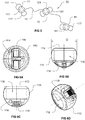
- a device 10 for pressure necrosis and tissue shearing comprises a first member 11 and a second member 12 connected to one another by a thread 13.
- Each of the first member 11 and second member 12 can comprise a generally dome shaped housing 110 advantageously made of a biocompatible material.
- the housing 110 encapsulates a material 111, 121 respectively.
- the materials 111, 121 encapsulated within the respective members 11, 12 show magnetic attraction to one another.
- both materials 111 and 121 can be permanent magnets.
- one material can be a permanent magnet, and the other one a material which is magnetically attracted to the permanent magnet, such as though not limited to a ferromagnetic material, e.g. an iron alloy.
- Each of the first member 11 and the second member comprises a generally planar surface of contact 112, 122 respectively, advantageously forming a bottom of the housing 110.
- the materials 111 and 121 advantageously have magnetic properties such that they show magnetic attraction when the first member and the second member are placed with their surface of contact 112, 122 against each other, e.g. through suitable orientation of the magnetic poles N and S of the permanent magnets within the housing 110. In use, therefore, the first and second members will be disposed in such a manner that the surfaces of contact 112, 122 are in facing relationship.
- Each of the first and second member further comprises a point of attachment 113 at which the thread 13 is connected to the respective member.
- the thread connection at 113 is advantageously a fixed connection, e.g. the thread 13 is fixedly secured, such as through tying or potting to the member.
- Each member 11, 12 may further comprise a suitable structure for facilitating handling of the member, e.g. an eye 114, allowing an endoscopic tool for engaging the respective member.
- the device 10 allows for creating an opening through a tissue wall separating two body cavities.
- the opening is larger than the size of any of the first member 11 and the second member 12.
- the members 11, 12 comprising the magnets 111, 121 are used, in a first step, for compressing tissue between oppositely arranged magnetically attracting members thereby causing pressure necrosis.
- the necrotic tissue collapses and forms an opening.
- the members 11, 12 lack support by the tissue and will fall through the opening created by necrosis.
- the members 11, 12 become suspended by thread 13 and will pull on the thread 13 due to gravity.
- the thread 13, supported by the tissue will start shearing the tissue to create a larger opening.
- FIGs. 2A-C A first possible application is shown in Figs. 2A-C and relates to treatment of diverticulum, such as though not limited to Zenker's diverticulum, which is a pouch 21 protruding from a lumen of the GI tract 20.
- the lumen 20 is the hypopharynx.
- the device 10 is introduced into the lumen 20 and the first member 11 placed in the pouch 21 while the second member 12 placed in the lumen 20 at a corresponding location.
- the device 10 can be introduced by any suitable endoscopic means. Since the pouch 21 is open towards the lumen 20, a delivery device, such as an endoscope with suitable system for engaging and positioning the members 11, 12, e.g.
- a grasper, forceps or specific catheter can be guided to the pouch 21 to place the first member 11. No tissue needs to be pierced in order to place member 11.
- the same endoscope or another endoscope can be guided to the adjacent lumen 20 to place the second member 12. It is alternatively possible to place the second member 12 first, and to place the first member 11 subsequently.
- the thread 13 is either connected to the two members 11 and 12 prior to loading the device 10 in the endoscope, or may be connected to either or both members upon placement.
- the thread 13 connecting the two members 11 and 12 does not pass through the tissue wall 23, but forms a loop over the periphery 24 of the tissue wall.
- the placement of the members can be guided with endoscopic ultrasound and/or fluoroscopy which are procedures well-known to persons skilled in the art of endoscopic procedures.
- the tissue wall 23 gets trapped between the two members and is compressed.
- a compression pressure larger than 5 mm Hg can be created, which is sufficient for stopping blood supply to the trapped tissue and hence causing necrosis of the tissue within a few days.
- the necrotic tissue trapped between the members 11 and 12 collapses and frees the members 11 and 12 which remain attached to one another and suspended on the thread 13.
- the first and second members and the thread now form a closed loop around the tissue wall 23, enclosing that portion of tissue interposed between the periphery 24 and the freshly formed necrotic opening.
- the members 11 and 12 Due to their weight, the members 11 and 12 now pull on the thread loop 13 in the direction of gravity. Referring to Fig. 2C , the thread 13 is now supported by the periphery 24 of the tissue wall and the tension in the thread 13 caused by the weight of the members 11 and 12 will start shearing the tissue from the periphery 24 until the initial opening 22 formed by necrosis is reached. The action of the thread 13 shearing the tissue wall 23 is represented in Figs. 3A-B from other viewing directions. By so doing, a lesion extending over the entire depth of the pouch 21 can be created without requiring recourse to larger structures and without requiring specific delivery devices.
- a lesion can be created extending over the distance by which the first member 11 and the second member 12 are spaced apart.
- the magnetically attracting members 11 and 12' of respective devices 10, 10' are placed in correspondence, each in the respective cavity. Portions of the tissue walls 42 and 43 of each respective cavity 40, 41 overlapping the members 11 and 12' are compressed.
- the other members 12 and 11' which also magnetically attract each other, are placed in correspondence, each in the respective cavity at a location spaced apart from the members 11 and 12'.
- Portions of the tissue walls 42 and 43 overlapping the members 12 and 11' are compressed.
- Members 11 and 12 are spaced apart from each other, such as by a distance of at least 40 mm, advantageously at least 50 mm to enable making a larger lesion.
- the tissue trapped between members 11 and 12' on the one hand and between members 12 and 11' on the other hand will become necrotic and collapse, which will free the members towards one cavity 40 or the other one 41.
- Either thread 13 or 13' will be pulled by the freed member couples 11-12' and 12-11' in the direction of gravity, which will shear the tissue in between the openings formed. It will be convenient to note that also in the case of Fig.
- FIG. 4 no puncture or piercing through the tissue wall is required for initial placement of the devices 10 and 10', as long as both cavities 40 and 41 are accessible.
- a configuration as in Fig. 4 may be useful for creating gastrojejunal anastomosis or jejuno-jejunal anastomosis.
- devices and assemblies described herein advantageously allow to perform tissue shearing assisted by pressure necrosis and/or compression anastomosis.
- device 50 shown in Fig. 5 comprises three members 11, 12 and 14 connected by thread 13. Two such devices 50 can be used in the same way as the example shown in Fig. 4 , each device being placed in a different one of the adjacent cavities 40 and 41, as with the devices 10 and 10'.
- the third member 14 may comprise its proper magnet 141 or magnetically active material.
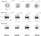
- the shape of the housing 110 of the members 11, 12 and possibly 14, and the shape of the magnets or magnetically active materials 111, 121 as well as of the surface of contact 112, 122 is not particularly limited. Suitable shapes and configurations may be chosen depending on any particular application. By way of example, instead of dome-shaped, such housing may be cylindrical, advantageously with planar top and bottom base. There is no preference for using the top or the bottom as surface of contact in the latter case.
- Each member can comprise a suitable handling structure for manipulating the member.
- the members 11, 12 and 14 can comprise one or more thread loops 117 which facilitate handling of the members by a forceps.
- the thread loops 117 project from the housing of the member and can be provided in addition or in alternative to other handling structures, such as the engagement eye.
- the engagement eye or hole 114, or the thread loop 117 as in Fig. 5 can be replaced by, or be supplemented with an advantageously ribbed projecting wall 115 allowing engagement by a forceps, e.g. of the types commonly used in endoscopic procedures.
- the magnet, or magnetically active material is received in interior and completely closed recess 116.
- the engagement hole 114 may be oriented parallel to the surface of contact 112, perpendicular thereto, or oblique.
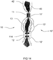
- Fig. 14 differs with respect to Fig. 4 only in the shape of the second members 12, 12' which comprise such a through-hole 114 and in which the magnets are advantageously annular surrounding the through-hole 114.
- the through-hole 114 allows to pass a medical tool, such as a needle, through the respective member 12, 12'.
- a necrotic tissue which may be anastomosed, is created surrounding the location of the through-hole 114, allowing a needle or other tool to pass through the tissues 42 and 43 safely.
- the surface of contact 112, 122 which defines the contact being made between the member and the tissue can be, but need not be, planar. Other kinds of shapes, such as concave, convex, stepped or staircase-like can be contemplated. It will be convenient to note that the surface of contact of members placed at opposite sides of the tissue wall, such as members 11 and 12 in Fig. 2 , and members 11 and 11' in Fig. 4 , may have a complementary shape. By way of example, the shapes shown in Fig. 8C, 8E and 8G may be complementary. In another example, two mushroom-shaped members as shown in Fig. 8G may be used. These mushroom-shaped members may form plugs or anchors preventing the magnetically attached members to fall through the tissues once the tissue becomes necrotic and collapses.
- the magnets 111, 121 can have any suitable shape. They may be monolithic within the housing 110, or made up of separate parts arranged adjacent one another, as shown in Figs. 9B-C . Other shapes than disc or cylindrical are possible, such as ring, oval or parallelepiped.
- a tension on the thread of at least 5 mm Hg may be sufficient for causing tissue shearing, with tensions of at least 10 mm Hg, at least 20 mm Hg, at least 50 mm Hg, or at least 100 mm Hg being advantageous.
- One possible way of accomplishing is by making one of the members slidable relative to the thread. Referring to Fig.
- device 60 differs from device 10 in that the second member 62 is not fixedly attached to the thread 13, but is allowed to slide along the thread.
- the first member 11 is attached to one end of the thread 13, and a mass member 63 is attached to the opposite end of thread 13, with the second member 62 being slidingly attached to thread 13 in between the first member 11 and the mass member 63.
- the second member 62 comprises a through hole 621 slidingly receiving thread 13.
- Mass member 63 has a suitable weight in order to provide a desired tension in thread 13, but will advantageously not be magnetically attracted to either one of the members 62 and 11.
- mass member 63 may not comprise any magnet or magnetically active material.
- Mass member may have a mass at least equal to 50%, 75% or 100% of the mass of any one of the members 11 and 12.
- the mass member 63 When members 11 and 62 are placed as shown in Fig. 2 , the mass member 63 is freely suspended and will pull on the thread 13 and put it under tension to immediately start shearing tissue. It will therefore be clear that device 60 allows for simultaneous pressure necrosis and tissue shearing.
- a yet alternative embodiment is obtained by adapting the arrangement 10 of Fig. 1 to include the mass member 63 interposed between the first member 11 and the second member 12. In this case, mass member 63 may, but need not be slidingly attached to the thread 13.
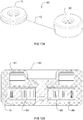
- Fig. 11A-B show alternative embodiments to the device 60, in which tension in the thread 13 is created through a thread winding system integrated within one of the members, or both.
- device 70 differs from device 10 in that the second member 72 comprises a thread winding system 74 for loading thread 13 in order to maintain tension in the thread.
- Thread winding system 74 can comprise a spiral spring 741 which is preloaded to pull on thread 13 according to a desired preload force acting in the direction of the arrow.
- Magnets 71 may be placed peripherally to thread winding system 74, as shown in Fig. 11A , or in any other suitable configuration.
- Fig. 11B an alternative to Fig.
- FIG. 11A is shown, which differs from device 70 in that the thread winding system 75 in the second member 73 is a spiral spring which is coiled around magnet 76, i.e., spring 73 and magnet 76 are concentric.
- the arrangement of Fig. 10 is adapted to incorporate the thread winding system in the mass member 63.
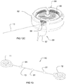
- FIG. 12A-C representing a device 80 comprising a thread winding system 84 incorporated in the second member 82.
- Device 80 differs from device 70 in the disposition of magnet 81 (see Fig. 12B ) which is annular and arranged above or below the thread winding system 84.
- magnet 81 see Fig. 12B
- possibly annular magnets may be arranged above and below the thread winding system, e.g. in a symmetrical fashion.
- the thread winding system 84 comprises a spiral spring operably connected to a pulley 86. Thread 13 is wound on pulley 86.
- Spiral spring 85 or any other suitable spring, is advantageously preloaded to apply a suitable torque on pulley 86 to pull on thread 13.
- the thread winding system 84 and the magnet 81 can be kept separated from one another without interference.
- a blocking system 89 can be provided in the second member 82 for blocking rotation of the thread winding system 84.
- blocking system 89 comprises a blocking member 88 which blocks the pulley 86 and/or the spiral spring 85, e.g. by engagement.
- the blocking system 89 is releasable, e.g. by pulling on thread 87 attached to blocking member 88, the blocking member 88 is released and the pulley and spiral spring can turn and wind the thread 13.
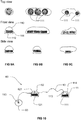
- a yet alternative embodiment is shown, which differs from device 10 in that a plurality of third members 91 are attached along the thread 13, between the first member 11 and the second member 12.
- the third members may be arranged with advantageously uniform spacing between one another and they are advantageously fixed to thread 13.
- the third members advantageously show magnetic attraction to the first member 11 and/or the second member 12 and act here as thread pulling means. As the tissue is further sheared, the third member 91 closest to the first member 11 will progressively move to the first member due to the magnetic attraction.
- the third members 91 can have any suitable shape, e.g. beads, and advantageously have dimensions substantially smaller than those of the first member and second member, e.g. half or less of the size of the first member and/or second member.
- an elastic or resilient thread to couple the members to one another.
- This thread is advantageously preloaded prior to placement of the device, e.g. by providing an appropriate structure which maintains the members at a distance larger than the length of the thread at rest, which structure is removed upon installing the device. The thread is stretched and thereby preloaded.
- the thread may be made of, or comprise a shape memory material. Suitable shape memory materials are shape memory polymers or (metal) alloys, which e.g. can retract at a body temperature level.
- DiAPLEX® commercialised by Mitsubishi Corporation Fashion Co., Ltd., Japan.
- a mass member pulling on the thread, of a traction system, or of elastic or resilient thread can be advantageously used in the application referred to in Fig. 4 . That is, either one or both the devices 10 and 10' in Fig. 4 may be provided with means for (pre)loading the thread 13, 13'. In the example of Fig. 4 , (pre)loading the threads 13, 13' with tensile stress enhances fusion between the tissues 42 and 43.
- the thread is advantageously made of a non-resorbable material, and is advantageously a monofilament thread, e.g. made of polyamide.
- the shape of the housing 110 is advantageously atraumatic. While in the above embodiments, only one thread is described extending between the first member and the second member, it will be convenient to note that a plurality of such threads, e.g. two, three or more can be provided to extend between, and be connected to the first member and second member.
- the means for pulling the thread may be operable to pull some or all of these threads. Multiple threads advantageously allow for shearing tissue across multiple, spaced apart sections.
- Each of the members has a diameter D (see Fig. 6B ) or largest size advantageously smaller than or equal to 40 mm, advantageously smaller than or equal to 30 mm, advantageously smaller than or equal to 20 mm, advantageously smaller than or equal to 15 mm, advantageously smaller than or equal to 20 mm.
- the member 11 or 12 can have a diameter or size of at least 5 mm, advantageously at least 10 mm.
- the thread 13 extending between the members has a length which in an initial placement position is advantageously at least 80 mm, advantageously at least 100 mm, advantageously at least 120 mm.
- the mass of the member 11 or 12 generally depends on the application, and may be determined on the basis of e.g. contact length of the thread with the tissue in order to arrive at a desired tension on the thread.
Landscapes
- Health & Medical Sciences (AREA)
- Surgery (AREA)
- Life Sciences & Earth Sciences (AREA)
- Engineering & Computer Science (AREA)
- Molecular Biology (AREA)
- Biomedical Technology (AREA)
- Heart & Thoracic Surgery (AREA)
- Medical Informatics (AREA)
- Nuclear Medicine, Radiotherapy & Molecular Imaging (AREA)
- Animal Behavior & Ethology (AREA)
- General Health & Medical Sciences (AREA)
- Public Health (AREA)
- Veterinary Medicine (AREA)
- General Engineering & Computer Science (AREA)
- Physiology (AREA)
- Mechanical Engineering (AREA)
- Surgical Instruments (AREA)
Claims (14)
- Vorrichtung (70, 80) zum Scheren von Gewebe in einem menschlichen oder tierischen Körper, umfassend:ein erstes Element (11), das ein erstes Material und eine erste Kontaktfläche (112) umfasst,ein zweites Element (12, 62, 72, 73, 82), das ein zweites Material und eine zweite Kontaktfläche (122) umfasst,wobei das erste und das zweite Material eine wechselseitige magnetische Anziehung aufweisen, wenn die erste und die zweite Kontaktfläche in einander zugewandtem Verhältnis angeordnet sind, undeinen Faden (13), der mit dem ersten Element und dem zweiten Element verbunden ist,wobei die Vorrichtung ein Mittel zum Ziehen des Fadens umfasst, das dafür gestaltet ist, eine Länge des Fadens zwischen dem ersten Element und dem zweiten Element zu verringern,dadurch gekennzeichnet, dass das Mittel zum Ziehen des Fadens ein Fadenaufwickelsystem (74, 75, 84) umfasst, das dafür gestaltet ist, zwischen dem ersten Element (11) und dem zweiten Element (72, 82) die Spannung in dem Faden aufrechtzuerhalten, und dadurch, dass das erste Element und/oder das zweite Element ein Gehäuse umfassen, wobei das Fadenaufwickelsystem in dem Gehäuse eingeschlossen ist.
- Vorrichtung nach Anspruch 1, wobei das Mittel zum Ziehen des Fadens dafür gestaltet ist, zwischen dem ersten Element und dem zweiten Element eine konstante Spannung auf den Faden anzulegen.
- Vorrichtung nach Anspruch 1 oder 2, wobei das erste Element und das zweite Element dafür gestaltet sind, aneinander angebracht zu sein, wobei das erste und das zweite Element und der Faden eine geschlossene Schlaufe bilden.
- Vorrichtung (60) zum Scheren von Gewebe in einem menschlichen oder tierischen Körper, umfassend:ein erstes Element (11), das ein erstes Material und eine erste Kontaktfläche (112) umfasst,ein zweites Element (12, 62, 72, 73, 82), das ein zweites Material und eine zweite Kontaktfläche (122) umfasst,wobei das erste und das zweite Material eine wechselseitige magnetische Anziehung aufweisen, wenn die erste und die zweite Kontaktfläche in einander zugewandtem Verhältnis angeordnet sind, undeinen Faden (13), der mit dem ersten Element und dem zweiten Element verbunden ist,wobei die Vorrichtung ein Mittel zum Ziehen des Fadens umfasst, das dafür gestaltet ist, eine Länge des Fadens zwischen dem ersten Element und dem zweiten Element zu verringern,dadurch gekennzeichnet, dass das Mittel zum Ziehen des Fadens ein drittes Element (63) umfasst, das mit dem Faden verbunden ist, wobei das zweite Element (62) gleitfähig mit dem Faden verbunden ist und das zweite Element (62) entlang des Fadens zwischen dem ersten Element (11) und dem dritten Element (63) eingesetzt ist.
- Vorrichtung nach Anspruch 4, wobei das dritte Element eine Masse umfasst, die dafür gestaltet ist, den Faden durch Schwerkraft zu ziehen.
- Vorrichtung nach Anspruch 1 oder 2, wobei das Mittel zum Ziehen des Fadens mehrere dritte Elemente (91) umfasst, die zwischen dem ersten Element (11) und dem zweiten Element (12) in Intervallen gegenseitiger Abstände mit dem Faden verbunden sind, wobei die mehreren dritten Elemente eine magnetische Anziehung an das erste Element und/oder das zweite Element zeigen.
- Vorrichtung nach Anspruch 4, wobei das Mittel zum Ziehen des Fadens ein Fadenaufwickelsystem (74, 75, 84) umfasst, das dafür gestaltet ist, den Faden zwischen dem ersten Element (11) und dem zweiten Element (72, 82) zu spannen.
- Vorrichtung nach Anspruch 1 oder 7, wobei das Fadenaufwickelsystem eine Feder (741, 85) umfasst, die vorgespannt ist, um den Faden (13) zu ziehen.
- Vorrichtung nach Anspruch 8, wobei die Feder (741, 85) eine Spiralfeder ist.
- Vorrichtung nach irgendeinem der vorhergehenden Ansprüche, wobei das erste Element und das zweite Element jeweils einen Durchmesser kleiner als oder gleich 30 mm aufweisen und wobei der Faden, der sich zwischen dem ersten Element und dem zweiten Element erstreckt, eine Länge von mindestens 100 mm aufweist.
- Vorrichtung nach irgendeinem der vorhergehenden Ansprüche, wobei das erste Element, das zweite Element oder sowohl das erste Element als auch das zweite Element einen zweiten Faden (117) umfassen, der an einem Gehäuse des entsprechenden Elements angebracht ist, wobei der zweite Faden eine Schlaufe außerhalb des Gehäuses bildet.
- Vorrichtung nach irgendeinem der Ansprüche 1 bis 10, wobei der Faden elastisch ist und wobei das Mittel zum Ziehen des Fadens eine lösbare Vorspannstruktur zum Vorspannen des Fadens umfasst.
- Vorrichtung nach irgendeinem der Ansprüche 1 bis 10, wobei der Faden ein Formgedächtnismaterial umfasst.
- Vorrichtung nach irgendeinem der vorhergehenden Ansprüche, wobei mindestens eines von dem ersten Element und dem zweiten Element (12) eine Durchgangsöffnung (114) umfasst, wobei das entsprechende erste oder zweite Material die Durchgangsöffnung umgibt.
Applications Claiming Priority (2)
| Application Number | Priority Date | Filing Date | Title |
|---|---|---|---|
| EP17158646 | 2017-03-01 | ||
| PCT/EP2018/055106 WO2018158395A1 (en) | 2017-03-01 | 2018-03-01 | Device for shearing tissue |
Publications (2)
| Publication Number | Publication Date |
|---|---|
| EP3589221A1 EP3589221A1 (de) | 2020-01-08 |
| EP3589221B1 true EP3589221B1 (de) | 2021-05-12 |
Family
ID=58192239
Family Applications (1)
| Application Number | Title | Priority Date | Filing Date |
|---|---|---|---|
| EP18708123.7A Active EP3589221B1 (de) | 2017-03-01 | 2018-03-01 | Vorrichtung zum schneiden von gewebe |
Country Status (6)
| Country | Link |
|---|---|
| US (2) | US11337722B2 (de) |
| EP (1) | EP3589221B1 (de) |
| JP (1) | JP2020508773A (de) |
| BR (1) | BR112019018069A2 (de) |
| CA (1) | CA3054990A1 (de) |
| WO (1) | WO2018158395A1 (de) |
Families Citing this family (16)
| Publication number | Priority date | Publication date | Assignee | Title |
|---|---|---|---|---|
| ES3004938T3 (en) | 2009-07-15 | 2025-03-13 | Gt Metabolic Solutions Inc | Incisionless gastric bypass devices |
| US8870898B2 (en) | 2010-01-05 | 2014-10-28 | GI Windows, Inc. | Self-assembling magnetic anastomosis device having an exoskeleton |
| US8828032B2 (en) | 2010-01-05 | 2014-09-09 | GI Windows, Inc. | Methods and apparatus for magnet-induced compression anastomosis between adjacent organs |
| ES3032508T3 (en) | 2015-03-12 | 2025-07-21 | Gi Windows Inc | Magnetic anastomosis devices with varying magnetic force at a distance |
| WO2019232527A1 (en) | 2018-06-02 | 2019-12-05 | G.I. Windows, Inc. | Systems, devices, and methods for forming anastomoses |
| EP4213744B1 (de) | 2020-09-18 | 2026-02-11 | GT Metabolic Solutions, Inc. | Anastomosebildung mit magnetischen vorrichtungen mit temporärem halteelement |
| WO2022132351A1 (en) | 2020-12-18 | 2022-06-23 | Gt Metabolic Solutions, Inc. | Devices and methods for assisting magnetic compression anastomosis |
| EP4326176A4 (de) | 2021-04-20 | 2025-03-12 | G.I. Windows, Inc. | Systeme, vorrichtungen und verfahren für endoskop oder laparoskopische magnetische navigation |
| EP4329638A4 (de) | 2021-04-30 | 2025-02-26 | GT Metabolic Solutions, Inc. | Anastomosebildung mit magnetischen vorrichtungen mit bioresorbierbarem halteelement |
| WO2022245458A1 (en) | 2021-05-20 | 2022-11-24 | G.I. Windows, Inc. | Systems, devices, and methods for forming anastomoses |
| KR102738689B1 (ko) * | 2021-12-15 | 2024-12-04 | 고려대학교 산학협력단 | 내시경 채널 삽입용 조직 견인 장치 |
| US12144507B2 (en) * | 2021-12-16 | 2024-11-19 | Cilag Gmbh International | Implantable sphincter assistance device with 3D printed shell weld interface geometry |
| USD1081998S1 (en) | 2022-03-17 | 2025-07-01 | Gt Metabolic Solutions, Inc. | Anastomosis formation device |
| CN119789819A (zh) | 2022-08-05 | 2025-04-08 | G.I.窗公司 | 具有多件式椎骨的磁压缩吻合装置 |
| US12070217B2 (en) | 2022-09-01 | 2024-08-27 | G.I. Windows, Inc. | Pressure profile magnetic compression anastomosis devices |
| JP2025529236A (ja) | 2022-09-02 | 2025-09-04 | ジーアイ ウィンドウズ, インコーポレイテッド | 内視鏡または腹腔鏡磁気ナビゲーションのためのシステム、デバイスおよび方法 |
Family Cites Families (20)
| Publication number | Priority date | Publication date | Assignee | Title |
|---|---|---|---|---|
| US5690656A (en) | 1995-06-27 | 1997-11-25 | Cook Incorporated | Method and apparatus for creating abdominal visceral anastomoses |
| US6648903B1 (en) * | 1998-09-08 | 2003-11-18 | Pierson, Iii Raymond H. | Medical tensioning system |
| JP3930757B2 (ja) * | 2002-04-10 | 2007-06-13 | 有限会社 パックス オプティカ ジャパン | 臓器吻合装置 |
| US20080300618A1 (en) * | 2004-03-23 | 2008-12-04 | Michael Eric Gertner | Obesity treatment systems |
| US8343031B2 (en) * | 2004-03-23 | 2013-01-01 | Michael Gertner | Obesity treatment systems |
| US8123768B2 (en) * | 2005-10-24 | 2012-02-28 | Gil Vardi | Method and system to restrict stomach size |
| WO2007147057A2 (en) * | 2006-06-14 | 2007-12-21 | University Of Florida Research Foundation, Inc. | Devices for adjustable, knotless tissue approximation |
| US20080200934A1 (en) * | 2007-02-15 | 2008-08-21 | Fox William D | Surgical devices and methods using magnetic force to form an anastomosis |
| US20080294175A1 (en) * | 2007-05-21 | 2008-11-27 | Epitek, Inc. | Left atrial appendage closure |
| US20090024144A1 (en) * | 2007-07-18 | 2009-01-22 | Zeiner Mark S | Hybrid endoscopic/laparoscopic device for forming serosa to serosa plications in a gastric cavity |
| EP2231029B1 (de) * | 2007-12-21 | 2023-08-16 | GT Metabolic Solutions, Inc. | Vorrichtungen zur endoskopischen erzeugung einer anastomose |
| US8679139B2 (en) * | 2009-04-03 | 2014-03-25 | Cook Medical Technologies Llc | Delivery system for magnetic anastomosis device |
| US8828032B2 (en) * | 2010-01-05 | 2014-09-09 | GI Windows, Inc. | Methods and apparatus for magnet-induced compression anastomosis between adjacent organs |
| WO2012007052A1 (en) | 2010-07-16 | 2012-01-19 | Ethicon Endo-Surgery, Inc. | A device for an endoluminal cholecysto - enterostomy |
| WO2013028390A1 (en) * | 2011-08-23 | 2013-02-28 | Torax Medical, Inc. | Medical implant with floating magnets |
| CN104619269B (zh) | 2012-09-07 | 2018-04-03 | 伊西康内外科公司 | 磁性压缩吻合装置 |
| CA2932285C (en) * | 2013-12-17 | 2019-10-08 | Standard Bariatrics, Inc. | Resection line guide for a medical procedure and method of using same |
| EP3488795A1 (de) | 2014-07-23 | 2019-05-29 | GI Windows Inc. | Magnetische anastomosevorrichtungen und verfahren zur freisetzung |
| US20180193050A1 (en) * | 2017-01-10 | 2018-07-12 | Empire Technology Development Llc | Diverticulum inverting device |
| US10631865B2 (en) * | 2017-01-30 | 2020-04-28 | Ethicon Llc | Tissue compression device with features to contain needles and suture during packaging and placement in body |
-
2018
- 2018-03-01 EP EP18708123.7A patent/EP3589221B1/de active Active
- 2018-03-01 US US16/489,584 patent/US11337722B2/en active Active
- 2018-03-01 WO PCT/EP2018/055106 patent/WO2018158395A1/en not_active Ceased
- 2018-03-01 BR BR112019018069-9A patent/BR112019018069A2/pt not_active Application Discontinuation
- 2018-03-01 CA CA3054990A patent/CA3054990A1/en not_active Abandoned
- 2018-03-01 JP JP2019547348A patent/JP2020508773A/ja active Pending
-
2022
- 2022-05-19 US US17/748,940 patent/US12220144B2/en active Active
Non-Patent Citations (1)
| Title |
|---|
| None * |
Also Published As
| Publication number | Publication date |
|---|---|
| JP2020508773A (ja) | 2020-03-26 |
| US20220273330A1 (en) | 2022-09-01 |
| BR112019018069A2 (pt) | 2020-07-28 |
| US11337722B2 (en) | 2022-05-24 |
| CA3054990A1 (en) | 2018-09-07 |
| WO2018158395A1 (en) | 2018-09-07 |
| US20200008834A1 (en) | 2020-01-09 |
| EP3589221A1 (de) | 2020-01-08 |
| US12220144B2 (en) | 2025-02-11 |
Similar Documents
| Publication | Publication Date | Title |
|---|---|---|
| US12220144B2 (en) | Method for shearing tissue | |
| US10779831B2 (en) | Systems, devices, and methods for forming anastomoses | |
| US11864767B2 (en) | Self-assembling magnetic anastomosis device having an exoskeleton | |
| US11547421B2 (en) | Hemostatic clipping devices and methods | |
| JP6668325B2 (ja) | 気腫性嚢胞の大きさを制御する方法及び装置 | |
| US8406901B2 (en) | Sutureless implantable medical device fixation | |
| EP3267905B1 (de) | Magnetische anastomosevorrichtung mit variierender magnetkraft bei einem abstand | |
| US7497822B1 (en) | Stomach reduction methods and apparatus | |
| JP5191489B2 (ja) | 摂食行動を変更するデバイス及び方法 | |
| EP2413810B1 (de) | Gewebeanker und medizinprodukte zur schnellen ablage von gewebeankern | |
| CN109925046A (zh) | 组织紧固工具和组织紧固系统 | |
| WO2022225919A1 (en) | Systems, devices, and methods for delivering and positioning magnetic anastomosis compression devices for subsequent formation of anastomoses | |
| AU2007201267B2 (en) | Compliant gastroplasty: Devices and methods | |
| US20180098770A1 (en) | Controlling a Size of a Pyloris | |
| CN121752204A (zh) | 用于定位磁性植入物以用于在消化道中的目标位置处形成吻合的系统和方法 | |
| Gong | Design, development and testing of miniature instruments for flexible endoscopy |
Legal Events
| Date | Code | Title | Description |
|---|---|---|---|
| STAA | Information on the status of an ep patent application or granted ep patent |
Free format text: STATUS: UNKNOWN |
|
| STAA | Information on the status of an ep patent application or granted ep patent |
Free format text: STATUS: THE INTERNATIONAL PUBLICATION HAS BEEN MADE |
|
| PUAI | Public reference made under article 153(3) epc to a published international application that has entered the european phase |
Free format text: ORIGINAL CODE: 0009012 |
|
| STAA | Information on the status of an ep patent application or granted ep patent |
Free format text: STATUS: REQUEST FOR EXAMINATION WAS MADE |
|
| 17P | Request for examination filed |
Effective date: 20190828 |
|
| AK | Designated contracting states |
Kind code of ref document: A1 Designated state(s): AL AT BE BG CH CY CZ DE DK EE ES FI FR GB GR HR HU IE IS IT LI LT LU LV MC MK MT NL NO PL PT RO RS SE SI SK SM TR |
|
| AX | Request for extension of the european patent |
Extension state: BA ME |
|
| DAV | Request for validation of the european patent (deleted) | ||
| DAX | Request for extension of the european patent (deleted) | ||
| GRAP | Despatch of communication of intention to grant a patent |
Free format text: ORIGINAL CODE: EPIDOSNIGR1 |
|
| STAA | Information on the status of an ep patent application or granted ep patent |
Free format text: STATUS: GRANT OF PATENT IS INTENDED |
|
| RIC1 | Information provided on ipc code assigned before grant |
Ipc: A61B 17/11 20060101ALI20201119BHEP Ipc: A61B 17/3209 20060101ALN20201119BHEP Ipc: A61B 17/00 20060101ALN20201119BHEP Ipc: F16H 7/08 20060101ALN20201119BHEP Ipc: A61B 17/3205 20060101AFI20201119BHEP Ipc: A61B 17/06 20060101ALN20201119BHEP Ipc: A61B 17/32 20060101ALN20201119BHEP Ipc: A61B 17/04 20060101ALN20201119BHEP |
|
| RIC1 | Information provided on ipc code assigned before grant |
Ipc: A61B 17/00 20060101ALN20201130BHEP Ipc: A61B 17/11 20060101ALI20201130BHEP Ipc: F16H 7/08 20060101ALN20201130BHEP Ipc: A61B 17/04 20060101ALN20201130BHEP Ipc: A61B 17/32 20060101ALN20201130BHEP Ipc: A61B 17/3205 20060101AFI20201130BHEP Ipc: A61B 17/06 20060101ALN20201130BHEP Ipc: A61B 17/3209 20060101ALN20201130BHEP |
|
| INTG | Intention to grant announced |
Effective date: 20201214 |
|
| GRAS | Grant fee paid |
Free format text: ORIGINAL CODE: EPIDOSNIGR3 |
|
| GRAA | (expected) grant |
Free format text: ORIGINAL CODE: 0009210 |
|
| STAA | Information on the status of an ep patent application or granted ep patent |
Free format text: STATUS: THE PATENT HAS BEEN GRANTED |
|
| AK | Designated contracting states |
Kind code of ref document: B1 Designated state(s): AL AT BE BG CH CY CZ DE DK EE ES FI FR GB GR HR HU IE IS IT LI LT LU LV MC MK MT NL NO PL PT RO RS SE SI SK SM TR |
|
| REG | Reference to a national code |
Ref country code: GB Ref legal event code: FG4D |
|
| REG | Reference to a national code |
Ref country code: CH Ref legal event code: EP |
|
| REG | Reference to a national code |
Ref country code: DE Ref legal event code: R096 Ref document number: 602018017018 Country of ref document: DE |
|
| REG | Reference to a national code |
Ref country code: IE Ref legal event code: FG4D |
|
| REG | Reference to a national code |
Ref country code: AT Ref legal event code: REF Ref document number: 1391647 Country of ref document: AT Kind code of ref document: T Effective date: 20210615 |
|
| REG | Reference to a national code |
Ref country code: LT Ref legal event code: MG9D |
|
| REG | Reference to a national code |
Ref country code: AT Ref legal event code: MK05 Ref document number: 1391647 Country of ref document: AT Kind code of ref document: T Effective date: 20210512 |
|
| REG | Reference to a national code |
Ref country code: NL Ref legal event code: MP Effective date: 20210512 |
|
| PG25 | Lapsed in a contracting state [announced via postgrant information from national office to epo] |
Ref country code: BG Free format text: LAPSE BECAUSE OF FAILURE TO SUBMIT A TRANSLATION OF THE DESCRIPTION OR TO PAY THE FEE WITHIN THE PRESCRIBED TIME-LIMIT Effective date: 20210812 Ref country code: AT Free format text: LAPSE BECAUSE OF FAILURE TO SUBMIT A TRANSLATION OF THE DESCRIPTION OR TO PAY THE FEE WITHIN THE PRESCRIBED TIME-LIMIT Effective date: 20210512 Ref country code: FI Free format text: LAPSE BECAUSE OF FAILURE TO SUBMIT A TRANSLATION OF THE DESCRIPTION OR TO PAY THE FEE WITHIN THE PRESCRIBED TIME-LIMIT Effective date: 20210512 Ref country code: HR Free format text: LAPSE BECAUSE OF FAILURE TO SUBMIT A TRANSLATION OF THE DESCRIPTION OR TO PAY THE FEE WITHIN THE PRESCRIBED TIME-LIMIT Effective date: 20210512 Ref country code: LT Free format text: LAPSE BECAUSE OF FAILURE TO SUBMIT A TRANSLATION OF THE DESCRIPTION OR TO PAY THE FEE WITHIN THE PRESCRIBED TIME-LIMIT Effective date: 20210512 |
|
| PG25 | Lapsed in a contracting state [announced via postgrant information from national office to epo] |
Ref country code: PT Free format text: LAPSE BECAUSE OF FAILURE TO SUBMIT A TRANSLATION OF THE DESCRIPTION OR TO PAY THE FEE WITHIN THE PRESCRIBED TIME-LIMIT Effective date: 20210913 Ref country code: PL Free format text: LAPSE BECAUSE OF FAILURE TO SUBMIT A TRANSLATION OF THE DESCRIPTION OR TO PAY THE FEE WITHIN THE PRESCRIBED TIME-LIMIT Effective date: 20210512 Ref country code: LV Free format text: LAPSE BECAUSE OF FAILURE TO SUBMIT A TRANSLATION OF THE DESCRIPTION OR TO PAY THE FEE WITHIN THE PRESCRIBED TIME-LIMIT Effective date: 20210512 Ref country code: NO Free format text: LAPSE BECAUSE OF FAILURE TO SUBMIT A TRANSLATION OF THE DESCRIPTION OR TO PAY THE FEE WITHIN THE PRESCRIBED TIME-LIMIT Effective date: 20210812 Ref country code: SE Free format text: LAPSE BECAUSE OF FAILURE TO SUBMIT A TRANSLATION OF THE DESCRIPTION OR TO PAY THE FEE WITHIN THE PRESCRIBED TIME-LIMIT Effective date: 20210512 Ref country code: RS Free format text: LAPSE BECAUSE OF FAILURE TO SUBMIT A TRANSLATION OF THE DESCRIPTION OR TO PAY THE FEE WITHIN THE PRESCRIBED TIME-LIMIT Effective date: 20210512 Ref country code: IS Free format text: LAPSE BECAUSE OF FAILURE TO SUBMIT A TRANSLATION OF THE DESCRIPTION OR TO PAY THE FEE WITHIN THE PRESCRIBED TIME-LIMIT Effective date: 20210912 Ref country code: GR Free format text: LAPSE BECAUSE OF FAILURE TO SUBMIT A TRANSLATION OF THE DESCRIPTION OR TO PAY THE FEE WITHIN THE PRESCRIBED TIME-LIMIT Effective date: 20210813 |
|
| PG25 | Lapsed in a contracting state [announced via postgrant information from national office to epo] |
Ref country code: NL Free format text: LAPSE BECAUSE OF FAILURE TO SUBMIT A TRANSLATION OF THE DESCRIPTION OR TO PAY THE FEE WITHIN THE PRESCRIBED TIME-LIMIT Effective date: 20210512 |
|
| PG25 | Lapsed in a contracting state [announced via postgrant information from national office to epo] |
Ref country code: ES Free format text: LAPSE BECAUSE OF FAILURE TO SUBMIT A TRANSLATION OF THE DESCRIPTION OR TO PAY THE FEE WITHIN THE PRESCRIBED TIME-LIMIT Effective date: 20210512 Ref country code: EE Free format text: LAPSE BECAUSE OF FAILURE TO SUBMIT A TRANSLATION OF THE DESCRIPTION OR TO PAY THE FEE WITHIN THE PRESCRIBED TIME-LIMIT Effective date: 20210512 Ref country code: SK Free format text: LAPSE BECAUSE OF FAILURE TO SUBMIT A TRANSLATION OF THE DESCRIPTION OR TO PAY THE FEE WITHIN THE PRESCRIBED TIME-LIMIT Effective date: 20210512 Ref country code: SM Free format text: LAPSE BECAUSE OF FAILURE TO SUBMIT A TRANSLATION OF THE DESCRIPTION OR TO PAY THE FEE WITHIN THE PRESCRIBED TIME-LIMIT Effective date: 20210512 Ref country code: RO Free format text: LAPSE BECAUSE OF FAILURE TO SUBMIT A TRANSLATION OF THE DESCRIPTION OR TO PAY THE FEE WITHIN THE PRESCRIBED TIME-LIMIT Effective date: 20210512 Ref country code: CZ Free format text: LAPSE BECAUSE OF FAILURE TO SUBMIT A TRANSLATION OF THE DESCRIPTION OR TO PAY THE FEE WITHIN THE PRESCRIBED TIME-LIMIT Effective date: 20210512 Ref country code: DK Free format text: LAPSE BECAUSE OF FAILURE TO SUBMIT A TRANSLATION OF THE DESCRIPTION OR TO PAY THE FEE WITHIN THE PRESCRIBED TIME-LIMIT Effective date: 20210512 |
|
| REG | Reference to a national code |
Ref country code: DE Ref legal event code: R097 Ref document number: 602018017018 Country of ref document: DE |
|
| PLBE | No opposition filed within time limit |
Free format text: ORIGINAL CODE: 0009261 |
|
| STAA | Information on the status of an ep patent application or granted ep patent |
Free format text: STATUS: NO OPPOSITION FILED WITHIN TIME LIMIT |
|
| 26N | No opposition filed |
Effective date: 20220215 |
|
| PG25 | Lapsed in a contracting state [announced via postgrant information from national office to epo] |
Ref country code: IS Free format text: LAPSE BECAUSE OF FAILURE TO SUBMIT A TRANSLATION OF THE DESCRIPTION OR TO PAY THE FEE WITHIN THE PRESCRIBED TIME-LIMIT Effective date: 20210912 Ref country code: AL Free format text: LAPSE BECAUSE OF FAILURE TO SUBMIT A TRANSLATION OF THE DESCRIPTION OR TO PAY THE FEE WITHIN THE PRESCRIBED TIME-LIMIT Effective date: 20210512 |
|
| PG25 | Lapsed in a contracting state [announced via postgrant information from national office to epo] |
Ref country code: IT Free format text: LAPSE BECAUSE OF FAILURE TO SUBMIT A TRANSLATION OF THE DESCRIPTION OR TO PAY THE FEE WITHIN THE PRESCRIBED TIME-LIMIT Effective date: 20210512 |
|
| PG25 | Lapsed in a contracting state [announced via postgrant information from national office to epo] |
Ref country code: MC Free format text: LAPSE BECAUSE OF FAILURE TO SUBMIT A TRANSLATION OF THE DESCRIPTION OR TO PAY THE FEE WITHIN THE PRESCRIBED TIME-LIMIT Effective date: 20210512 |
|
| REG | Reference to a national code |
Ref country code: CH Ref legal event code: PL |
|
| PG25 | Lapsed in a contracting state [announced via postgrant information from national office to epo] |
Ref country code: LU Free format text: LAPSE BECAUSE OF NON-PAYMENT OF DUE FEES Effective date: 20220301 Ref country code: LI Free format text: LAPSE BECAUSE OF NON-PAYMENT OF DUE FEES Effective date: 20220331 Ref country code: IE Free format text: LAPSE BECAUSE OF NON-PAYMENT OF DUE FEES Effective date: 20220301 Ref country code: CH Free format text: LAPSE BECAUSE OF NON-PAYMENT OF DUE FEES Effective date: 20220331 |
|
| PG25 | Lapsed in a contracting state [announced via postgrant information from national office to epo] |
Ref country code: MK Free format text: LAPSE BECAUSE OF FAILURE TO SUBMIT A TRANSLATION OF THE DESCRIPTION OR TO PAY THE FEE WITHIN THE PRESCRIBED TIME-LIMIT Effective date: 20210512 Ref country code: CY Free format text: LAPSE BECAUSE OF FAILURE TO SUBMIT A TRANSLATION OF THE DESCRIPTION OR TO PAY THE FEE WITHIN THE PRESCRIBED TIME-LIMIT Effective date: 20210512 |
|
| PG25 | Lapsed in a contracting state [announced via postgrant information from national office to epo] |
Ref country code: HU Free format text: LAPSE BECAUSE OF FAILURE TO SUBMIT A TRANSLATION OF THE DESCRIPTION OR TO PAY THE FEE WITHIN THE PRESCRIBED TIME-LIMIT; INVALID AB INITIO Effective date: 20180301 |
|
| PG25 | Lapsed in a contracting state [announced via postgrant information from national office to epo] |
Ref country code: TR Free format text: LAPSE BECAUSE OF FAILURE TO SUBMIT A TRANSLATION OF THE DESCRIPTION OR TO PAY THE FEE WITHIN THE PRESCRIBED TIME-LIMIT Effective date: 20210512 |
|
| PG25 | Lapsed in a contracting state [announced via postgrant information from national office to epo] |
Ref country code: MT Free format text: LAPSE BECAUSE OF FAILURE TO SUBMIT A TRANSLATION OF THE DESCRIPTION OR TO PAY THE FEE WITHIN THE PRESCRIBED TIME-LIMIT Effective date: 20210512 |
|
| P01 | Opt-out of the competence of the unified patent court (upc) registered |
Free format text: CASE NUMBER: UPC_APP_0019358_3589221/2025 Effective date: 20251223 |
|
| PGFP | Annual fee paid to national office [announced via postgrant information from national office to epo] |
Ref country code: GB Payment date: 20260219 Year of fee payment: 9 |
|
| PGFP | Annual fee paid to national office [announced via postgrant information from national office to epo] |
Ref country code: DE Payment date: 20260219 Year of fee payment: 9 |
|
| PGFP | Annual fee paid to national office [announced via postgrant information from national office to epo] |
Ref country code: BE Payment date: 20260219 Year of fee payment: 9 |
|
| PGFP | Annual fee paid to national office [announced via postgrant information from national office to epo] |
Ref country code: FR Payment date: 20260219 Year of fee payment: 9 |