EP3589219B1 - Handheld surgical instrument - Google Patents
Handheld surgical instrument Download PDFInfo
- Publication number
- EP3589219B1 EP3589219B1 EP18761842.6A EP18761842A EP3589219B1 EP 3589219 B1 EP3589219 B1 EP 3589219B1 EP 18761842 A EP18761842 A EP 18761842A EP 3589219 B1 EP3589219 B1 EP 3589219B1
- Authority
- EP
- European Patent Office
- Prior art keywords
- tip
- storage element
- instrument
- energy storage
- energy
- Prior art date
- Legal status (The legal status is an assumption and is not a legal conclusion. Google has not performed a legal analysis and makes no representation as to the accuracy of the status listed.)
- Active
Links
Images


Classifications
-
- A—HUMAN NECESSITIES
- A61—MEDICAL OR VETERINARY SCIENCE; HYGIENE
- A61B—DIAGNOSIS; SURGERY; IDENTIFICATION
- A61B17/00—Surgical instruments, devices or methods
- A61B17/16—Instruments for performing osteoclasis; Drills or chisels for bones; Trepans
- A61B17/1613—Component parts
- A61B17/1631—Special drive shafts, e.g. flexible shafts
-
- A—HUMAN NECESSITIES
- A61—MEDICAL OR VETERINARY SCIENCE; HYGIENE
- A61B—DIAGNOSIS; SURGERY; IDENTIFICATION
- A61B17/00—Surgical instruments, devices or methods
- A61B17/16—Instruments for performing osteoclasis; Drills or chisels for bones; Trepans
- A61B17/1604—Chisels; Rongeurs; Punches; Stamps
-
- A—HUMAN NECESSITIES
- A61—MEDICAL OR VETERINARY SCIENCE; HYGIENE
- A61B—DIAGNOSIS; SURGERY; IDENTIFICATION
- A61B17/00—Surgical instruments, devices or methods
- A61B17/16—Instruments for performing osteoclasis; Drills or chisels for bones; Trepans
- A61B17/1613—Component parts
- A61B17/1622—Drill handpieces
-
- A—HUMAN NECESSITIES
- A61—MEDICAL OR VETERINARY SCIENCE; HYGIENE
- A61B—DIAGNOSIS; SURGERY; IDENTIFICATION
- A61B17/00—Surgical instruments, devices or methods
- A61B17/16—Instruments for performing osteoclasis; Drills or chisels for bones; Trepans
- A61B17/1637—Hollow drills or saws producing a curved cut, e.g. cylindrical
-
- A—HUMAN NECESSITIES
- A61—MEDICAL OR VETERINARY SCIENCE; HYGIENE
- A61B—DIAGNOSIS; SURGERY; IDENTIFICATION
- A61B17/00—Surgical instruments, devices or methods
- A61B2017/00367—Details of actuation of instruments, e.g. relations between pushing buttons, or the like, and activation of the tool, working tip, or the like
- A61B2017/00411—Details of actuation of instruments, e.g. relations between pushing buttons, or the like, and activation of the tool, working tip, or the like actuated by application of energy from an energy source outside the body
-
- A—HUMAN NECESSITIES
- A61—MEDICAL OR VETERINARY SCIENCE; HYGIENE
- A61B—DIAGNOSIS; SURGERY; IDENTIFICATION
- A61B17/00—Surgical instruments, devices or methods
- A61B2017/0046—Surgical instruments, devices or methods with a releasable handle; with handle and operating part separable
- A61B2017/00473—Distal part, e.g. tip or head
-
- A—HUMAN NECESSITIES
- A61—MEDICAL OR VETERINARY SCIENCE; HYGIENE
- A61B—DIAGNOSIS; SURGERY; IDENTIFICATION
- A61B17/00—Surgical instruments, devices or methods
- A61B2017/00681—Aspects not otherwise provided for
- A61B2017/00734—Aspects not otherwise provided for battery operated
-
- A—HUMAN NECESSITIES
- A61—MEDICAL OR VETERINARY SCIENCE; HYGIENE
- A61B—DIAGNOSIS; SURGERY; IDENTIFICATION
- A61B17/00—Surgical instruments, devices or methods
- A61B17/56—Surgical instruments or methods for treatment of bones or joints; Devices specially adapted therefor
- A61B17/58—Surgical instruments or methods for treatment of bones or joints; Devices specially adapted therefor for osteosynthesis, e.g. bone plates, screws or setting implements
- A61B17/88—Osteosynthesis instruments; Methods or means for implanting or extracting internal or external fixation devices
- A61B17/92—Impactors or extractors, e.g. for removing intramedullary devices
- A61B2017/922—Devices for impaction, impact element
- A61B2017/924—Impact element driving means
Definitions
- the present invention is generally directed to a device for surgery, and more particularly, for accessing bone marrow for enhancement of tissue repair.
- One popular example use is performing automated microfracture on subchondral bone to repair articular cartilage.
- Other examples include the stimulation of healing in areas of tendinosis such as elbow lateral epicondylitis, patella tendinopathy, hip gluteus medius tendinopathy, and ankle achilles tendinitis; to stimulate ligament healing such as in knee medial collateral ligament sprains; to enhance soft tissue to bone healing such as in the repair of the shoulder rotator cuff tendon to bone; for the enhancement of bony healing in fractures; and in the preparation of bone for improved healing to prosthetic implants.
- Bone marrow and its associated cells are known to have regenerative properties which makes it valuable medicinally in areas of wear, damage, or impairment. In many cases, soft tissue and bone healing can benefit from improved access to bone marrow, typically through small holes in bone.
- One area of benefit is in articular cartilage repair.
- Articular cartilage is a smooth, low-friction tissue which covers the ends of bones and enables healthy joint function. Articular cartilage is prone to damage from excessive wear or traumatic injuries, as are common in sports. When articular cartilage is damaged, it can result in pain and reduced mobility for the patient, and in some cases subsequent arthritis. Articular cartilage has extremely limited ability to repair itself spontaneously due to absent blood flow.
- Microfracture surgery exists as a method to assist in the repair of articular cartilage in order to improve joint function.
- Microfracture creates a pathway for cartilage-building cells in blood and bone marrow to travel from the underlying cancellous bone to the articular surface by producing small holes in the cortical bone.
- Microfracture procedures are typically performed using an awl or a pick that is hit with a hammer.
- Some marrow access devices for example US9510840 ("the '840 patent), are utilized via driving a wire with a hammer through an angled cannula. Like the hammer and awl method, this method requires a minimum of three hands to operate, and delivers inconsistent results due to its subjective and uncontrolled external force delivery, which is a problem in microfracture procedures. Furthermore, the awl-like design and its associated user experience of applying aggressive, torsional, radial and axial force to remove the tip can result in tips breaking as documented in FDA MAUDE reports 3004154314-2013-00007, 3004154314-2013-00009, 3004154314-2016-00015, and several others.
- Some automated microfracture devices have been introduced which rely on external power sources such as compressed air or specialty electrical power supplies. This presents a challenge as many surgical facilities are without access to said power sources.
- Document US 2004/147932 A1 discloses an automated microfracture instrument comprising: a hammer-biasing spring coupled to an impacting mechanism with a sharpened tip configured to impact a bone; a power transmission mechanism configured to transmit energy from the hammer-biasing spring to the impacting mechanism, wherein the power transmission mechanism includes a semi-flexible metal wire guided by a hollow shaft bent at its distal end, and a trigger mechanism configured to release energy from the energy storage element.
- a handheld surgical instrument (10b) comprising: an energy storage element, wherein the energy storage element is a spring coupled to an impacting mechanism; an impacting mechanism having a tip with a tapered point configured to impact a bone; a power transmission mechanism configured to transmit energy from the energy storage element to the impacting mechanism; a trigger button configured to release energy from the energy storage element, a handle and a manual lever, wherein the manual lever, when actuated towards the handle charges the energy storage element.
- the typical method of performing microfracture involves holding a longitudinal awl with an angled tip, and a hammer for impacting the proximal end of the handle of said awl.
- a surgical scope must be held and positioned in a manner which allows the surgeon to see the tip alignment, the depth of penetration, and the subsequent blood flow from each hole produced.
- a problem exists in that at least three hands are required to perform such a procedure using the historically accepted method. While each tool must be operated with careful precision, and the feedback from each tool is interdependent, coordinating a microfracture procedure with a minimum of two operators presents a challenge.
- the depth of penetration must be sufficient to adequately access the bone marrow elements underneath the relatively avascular subchondral bone.
- the holes must be of sufficient width to allow bone marrow and blood to reach the surface of the bone, while not being so large as to significantly affect the load-bearing characteristics of the bone. Holes must be adequately spaced apart to allow for adequate flow to cover the surface, but not collapse into each other. Ideally, the holes should be perpendicular to the surface so that minimal tissue is perforated to allow access to the bone surface.
- the standard technique uses a hammer manually impacting the back end of the awl. This can result in a highly variable amount of force being applied, resulting in unpredictable hole size and depth. In addition, excessive load can cause significant bone edema, pain and loss of function in patients.
- the direction of force applied by the hammer is not substantially aligned with the orientation of the tip, and the tip may not be perpendicular to the bone surface. This often results in substantial undesired damage to the subchondral bone, since an oblique hole or trough may be created.
- the lateral force transmitted to the awl tip causes the tip to break into an adjacent hole, significantly disrupting the subchondral bone.
- the individual holes created may be much wider than what is necessary, leading to complications and prolonged recovery time.
- Another example application of the present invention is to improve access to bone marrow and blood to enhance soft tissue or bony healing, including fracture union, fusion, or healing to prosthetic implants.
- Insufficient access to bone marrow in said procedures can result in reduced progenitor cells and growth factors, and ultimately substandard clinical outcomes.
- this access is achieved either with the use of an awl, with the previously described deficiencies; or by drilling into the bone. Drilling of the bone has several limitations: typically, this is performed through an open and not minimally invasive surgical technique. The angle of drilling is usually limited by use of a straight drill bit. Larger holes can weaken the underlying bony tissue, while smaller drill bits are prone to breakage due to the often awkward positioning and unbalanced size of the power drill.
- Drilling has also been implicated in thermal necrosis (death) of the bone, which is counterproductive in the healing environment. This can be exacerbated by the typical reuse of many drill bits which become duller with continued use. Finally, drilling with the typical size drill and bit is usually a two handed procedure requiring an assistant to retract adjacent tissue.
- the present invention introduces a novel instrument for use in microfracture procedures and other bone marrow access procedures which solves the multiple issues mentioned above.
- the novel instrument can be operated using one hand, emulating both the hammer and the awl of the historically accepted microfracture procedure, or the stabilized drill and bit. In such form, one operator may coordinate each essential surgical element simultaneously with precision. Additionally, the device can have variable angles to access the bone, unlike a straight awl or drill bit.
- the present invention demonstrates a means of transmitting power to a force in a direction better aligned with the orientation of the tip. This device can deliver a precise load and direction to the tip, resulting in much better controlled hole size, shape, and depth. Another advantage is a disposable tip, which can also increase the average sharpness of the instrument when used.
- the present invention includes a handheld surgical instrument in accordance with claim 1.
- the invention includes a handheld surgical instrument in accordance with claim 14.
- the handheld surgical instrument (1000) houses a direct-drive carriage, which is connected to the power transmission mechanism (1300) and to the tip (1400), together forming the impact mechanism (1200).
- the proximal end of the tip and the semi-flexible wire within the bent shaft, that is the power transmission mechanism, are one in the same.
- the entire device is disposable, so as to ensure a safe and sterile procedure administered by the device.
- the tip is removable, and can be cleaned by standard reprocessing methods.
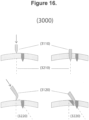
- the present invention includes a handheld surgical instrument having an energy storage element, wherein the energy storage element is a spring coupled to the impacting mechanism, the impacting mechanism having a tip configured to impact a bone, wherein the tip includes a tapered point, a power transmission mechanism is configured to transmit energy from the energy storage element to the impacting mechanism, wherein the power transmission mechanism includes a semi-flexible metal wire guided by a hollow shaft, wherein the hollow shaft includes a distal end, wherein the semi-flexible metal wire is includes a bend toward the distal end.
- a trigger mechanism is configured to release energy from the energy storage element, wherein the bend includes an angle between 14 degrees and 46 degrees, wherein the trigger mechanism includes a manual lever which, when actuated, simultaneously retracts the tip and charges the energy storage element.
- the invention includes a method of performing surgery that includes the use of a handheld surgical instrument comprising an energy storage element, wherein the energy storage element is a spring coupled to the impacting mechanism.
- An impacting mechanism has a tip configured to impact a bone, wherein the tip includes a tapered point.
- a power transmission mechanism is configured to transmit energy from the energy storage element to the impacting mechanism, wherein the power transmission mechanism includes a semi-flexible metal wire guided by a hollow shaft, wherein the hollow shaft includes a distal end.
- the semi-flexible metal wire is includes a bend toward the distal end.
- a trigger mechanism is configured to release energy from the energy storage element, wherein the bend includes an angle between 14 degrees and 46 degrees, wherein the trigger mechanism includes a manual lever which, when actuated, simultaneously retracts the tip and charges the energy storage element.
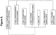
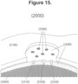
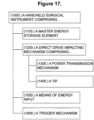
- the present invention comprises a handheld surgical instrument for creating holes in tissue.
- the instrument comprises six main parts, including a master energy storage element (1100); an impact mechanism (1200); a power transmission mechanism (1300); a tip (1400); a means of energy input (1500); and a trigger mechanism (1600).
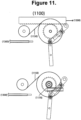
- the master energy storage element (1100) is a flat coil spring wound around two cylinders, one cylinder being the “storage drum", and the other being the “output drum”.
- this flat spring could be Vulcan Spring SV12J192.
- the flat coil spring in this assembly shall be referred to as a "constant torque spring”.
- the resulting torque is approximately 0.847 N.m (7.50 in-lbs)
- the output drum is fixed to a shaft which is also attached to a ratcheting mechanism.
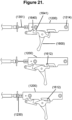
- the means of energy input (1500) could be achieved through a sliding handle which the user may operate to engage the ratcheting gear, rotating the output shaft, transferring the length of the flat coil spring to the output drum and "charging" the constant torque spring master energy storage element.
- the torque from the flat spring is used to charge the impact mechanism (1200) with a rack and pinion arrangement.
- the ratcheting pawl may be disengaged from the ratcheting gear by a user-operated lever, freeing the constant torque spring to do work.
- the pinion gear a 14.5 degree pressure angle, 20 tooth spur gear with a 1.651 cm (.625 inch) pitch diameter (McMaster 6867K553), is fixed to a shaft which is also fixed to the output drum.
- the pinion may engage with a fitting rack in order to compress a linear compression spring.
- the linear compression spring could be a 6.35 cm (2.50 inch) long stainless steel spring with a spring constant of 30.18 kg/mm (16.90 lbs/inch) which compresses to 3.38 cm (1.33 inches) (McMaster 1986K19).
- the linear spring produces 8.9689 kg (19.773 lbs) of force when fully compressed.
- a total force of 10.89 kg (24 lbs) can be applied to the rack and subsequently, the linear compression spring--enough to fully compress said spring.
- the rack has a slot which is used constrain it to sliding only, whereas the coupler of a parallel four bar mechanism is mated with the slot, and can be used to change the height of the slot with respect to the pinion, engaging or disengaging the rack with the pinion.
- the trigger (1600) is attached to the parallel four bar mechanism. Once the linear compression spring is fully compressed, the trigger can be used to disengage the rack from the pinion gear, "firing" a metal carriage which acts as an impacting mass for energy transfer. The impacting mass engages the power transmission mechanism (1300).
- the power transmission mechanism may consist of a stainless steel rod inside a stainless steel shaft on one side, and a plurality of tightly toleranced stainless steel balls, as a clearance fit, inside the other end of the shaft, which is optionally bent.
- the rod is held flush against the balls by an extension spring mated to the rod and when the impacting mass impacts the rod, energy is transferred through the balls to the tip, conserving momentum and providing output energy to the tip (1400).
- the tip may include a sharpened metal body with a blunt proximal end for engaging the distalmost stainless steel ball of the power transmission mechanism.
- the tip is constrained axially to the shaft but not rigidly fixed to said shaft.
- a small light compression spring is used as a buffer between the sharpened body and the shaft so that the majority of energy from the impacting drive mechanism may be applied to the sharpened tip body without the additional inertia of the shaft. The result is that the sharpened tip may engage the subchondral bone with majority axial force, driving to a sufficient depth and not producing any unnecessary damage to the subchondral bone.
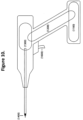
- the device exists as an attachment which can combine with existing tools as a means of providing an energy input, a handle, and/or a trigger.
- Figure 8 illustrates one possibility of how the block diagram in Figure 1 could be "short-circuited" or plugged into another device.
- the Means of Energy Input is a lever attached to the handle. Operating this lever could progressively charge the Energy Storage Element.
- the Impact Mechanism could optionally be triggered once the charge lever reaches a predetermined position.
- the Impact Mechanism could optionally be triggered by the user at any position, giving the user added control in the amount of force transmitted by the Impact Mechanism.
- the charge lever could optionally include a ratcheting mechanism for multiple operations by the user before triggering.
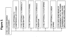
- the master energy storage element (1100) enables the device to store sufficient energy to match the requirement for the creation of two or more holes.
- the master energy storage element may include some means of engagement (1170) with the power transmission (1300) and/or the impact mechanism.
- the master energy storage element may exist, by way of example and not limitation, in one of the following forms; a compressed fluid chamber (1110); a chemically-based battery (1120); a mechanical flywheel (1130); a hydraulic reservoir (1140); a flat spring (1150); a linear spring (1160).
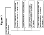
- the impact mechanism provides a means by which to apply a force to ultimately be transmitted to the tip for the creation of one or more holes.
- the impact mechanism may be charged (1210) by the master energy storage element (1100); and may also utilize a mechanism for the reduction of recoil (1220) on the user.
- the impact mechanism is optionally driven by a secondary energy storage element (1230). In one embodiment, the impact mechanism is driven directly by the master energy storage element (1240). In one embodiment, the impact mechanism provides a force to the power transmission mechanism (1300).
- the device includes a damper (1250) to soften the residual impact delivered by the impact mechanism.
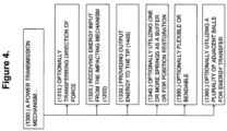
- the power transmission mechanism (1300) receives energy input from the impact mechanism (1320) or the master energy storage element; and provides a means by which to transmit power and provide output energy to the tip (1330); optionally utilizing one or more springs as a buffer or for position restoration (1340).
- the power transmission mechanism optionally transfers the direction of force (1310) applied by the impact mechanism. In one embodiment, the power transmission mechanism transfers the direction of force by 30 degrees. In another embodiment, the power transmission mechanism transfers the direction of force by 90 degrees.
- the power transmission mechanism is optionally enclosed in a flexible or bendable housing, and constructed in such a manner to allow for corresponding freedom of form (1350).
- the power transmission mechanism optionally utilizes one or more spherical bodies within a smooth, constrained pathway for the facilitation of efficient energy transfer (1360).
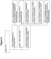
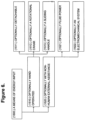
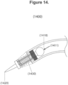
- the tip (1400) optionally exists as an assembly comprising of one or more springs (1430) to provide a buffer between attached bodies or for repositioning and comprises a proximal end (1410), which may be engaged by the power transmission mechanism; and a distal end (1420), optionally with a sharpened point (1421); optionally comprising one or more wires (1422); optionally with a chisel or drill-like geometry (1423); optionally comprising a multitude of impact points (1424).
- the tip optionally has a diameter of 1 millimeter or less in order to limit excessive damage to the subchondral bone, while still providing the necessary blood flow access for cartilage regeneration.
- the means of energy input (1500) allows a user to add energy to the devices energy storage elements for the subsequent utilization of internal mechanisms.
- the means of energy input is optionally hand operated (1510); the means of energy input is optionally performed utilizing non-human external assistance (1520).
- the means of energy input is detachable (1511).
- the means of energy input is a rotatable crank lever (1512).
- the means of energy input is a sliding handle (1513).
- the means of energy input could be in the form of fluid power (1521) or an electromechanical system (1522).
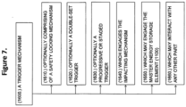
- the trigger mechanism (1600) provides a way to initiate mechanisms for the subsequent creation of holes in tissue and may interact with any other part in the device (1000) such as the impact mechanism (1640) or the master energy storage element (1650).
- the interface between the impact mechanism and the trigger mechanism optionally includes multiple detents (1641) to enable a ratcheting effect during energy input.
- the trigger mechanism optionally comprises of one or more safety locking mechanisms (1610) and is optionally a double set trigger, or optionally a progressive or staged trigger (1630).
- One embodiment of the safety mechanism is a pin (1611) that, when displaced in a particular direction, interferes with the firing operation of the trigger.
- Another embodiment of a safety mechanism is a separate track and body (1612) which together only allow firing of the trigger when the device is in a particular state.
- the impact mechanism, the transmission mechanism, and the tip are all connected to each other so as to accelerate the tip directly, without relying primarily on impact proximally within the device.
- the transmission mechanism may exist as a semi-flexible element (1351) such as a steel, nitinol, or titanium wire, which can traverse a bend in the shaft (1352) without failure.
- the drive carriage may be charged, triggered, and fired using a spring (1160) capable of storing enough energy to penetrate dense human tissue or bone.
- the drive carriage may be partially or fully decoupled from the handle body at the moment of impact by allowing the spring to accelerate the impact carriage and tip before impacting the tissue; Such configuration reduces device kick-back in the direction of the operator on impact.
- the handle body may include added weight for increased inertia and resulting decreased acceleration in the direction of the operator.
- the energy storage element (1100) may transfer energy for part of, or most of, the stroke of the direct drive carriage so as to reduce recoil or kick-back on the operator. It has been discovered that, with a sharpened surgical stainless steel tip of 1.0mm diameter, a kinetic energy of greater than 0.7 joules at the moment of impact results in sufficient depth of penetration (6 - 8mm) in 30# bone foam substrate, which closely resembles subchondral bone plate.
- the direct drive carriage is attached to a bundle of wires that make up the tip or several tips for simultaneous or sequential impact.
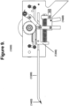
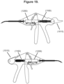
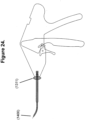
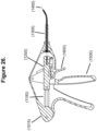
- Device may include a feature enabling the impacting tip (1400) to retract, or move proximally relative to the shaft, utilizing sufficient leverage to pull the tip out of the tissue after impacting.
- This leverage may be applied with one or more of the following, including but not limited to a screw, a cam, a roller, a slider crank, a pull wire, or some combination thereof.
- Figure 18 shows one example of this utilizing a cam and a roller (1514).
- this leverage is applied using the same hand that triggers the impact by way of a lever.
- this leverage is applied using a second hand.
- this mechanism is assisted by a spring.
- Retraction mechanism optionally utilizes a ratcheting or indexing mechanism, preventing premature triggering and/or enabling the user to operate retraction lever more than once so that sufficient mechanical advantage and stroke are attainable.
- the Device may include an element enabling the visualization of impact positioning before triggering impact.
- this feature exists as a stop point in the stroke of the tip (1425), such as that enabled by a locking pawl. In doing so, the operator may do a portion of, or a majority of drive carriage charging before placing in position, reducing the stability disturbance and alignment challenge while charging, and also exhibiting precise placement of the impacting tip.
- the visualization element exists as a separate body from the impacting tip.
- the visualization element could attach to the primary drive wire by means of element including but not limited to a wire, a spring, a channel or other body.
- the visualization element is a laser.
- the visualization element is a focused stream of fluid.
- this depth indicator optionally features a depth indicator on the handle body or shaft to show relative or absolute depth of penetration into the tissue.
- this indicator exists as a marker on the drive carriage (1201), viewable through an opening in the side of the handle body, for which the distance from the marker to the end of the tip is constant at the moment after impact.
- This depth indicator optionally features a finite set of two or more result indicators (1202), for example and not limitation, a binary indicator to indicate sufficient depth or not sufficient depth, or a scaled indicator to indicate what range or percentile of depth penetration was achieved.
- This feature is optionally embodied by an infinite relative position indicator window which may or may not have guiding markings on it.
- the markings on the indicator depict a typical range of thicknesses of cortical bone, to assist the operator in conceptualizing the resulting impact depth.
- the device may be assembled, packaged, and shipped with the main energy storage element completely uncharged, or partially uncharged.
- the user may prime the device when it is ready for use by introducing initial single operation energy input. In doing so at this stage as opposed to upon assembly of the device and before storage of the device reduces possibility of creep, wear, and deformation.
- the act of priming the device may also serve as a means to communicate to the user that the device is now ready for use and should be handled as such.
- the means of delivering initial energy input to prime the device is a rotational cam (1515) that interfaces with one end of a spring.
- a leveraging element for priming may be attached to or shipped with the device.
- the semi-flexible drive element and/or the shaft may be produced or processed in such a way to yield an interface or multiple interfaces with low coefficients of friction. This may be done with a smooth or lubricious coating such as a PTFE or EPTFE or biocompatible lubricant. This may be achieved with a metal impregnated with a biocompatible lubricant. This may be achieved with a surface treatment to bare wire such as polishing, plating or lapping. Internal friction may be reduced by reducing the total surface area in contact between the inside of the shaft and the outside of the drive element, such as one or more surrounding collars applying the pressure instead of solely the inner wall of the cannula or shaft applying pressure.
- the shaft or cannula may feature a non-uniform axial profile (1441) in order to optimize one or more of the following: stiffness, accessibility, control, and/or visualization. In one embodiment, this is done with two or more nested tubes of different diameters, optionally welded for rigidity.
- this is done with a single shaft, stepped and/or gradually tapered down its length.
- the distal tip of the shaft or cannula has a sharp edge (1442), whether straight, jagged, segmented or otherwise. This sharp edge could be on the interior diameter, outer diameter, or both.
- the device optionally includes a mechanism (1311) allowing the shaft or cannula to rotate on its primary axis, improving control and ergonomic functionality by modifying the direction of impact relative to the operator's hand.
- this mechanism exists as two or more finite positions of angular displacement.
- this mechanism exists as a joint of infinite angular positioning.
- this articulation can be actively controlled with the same hand that holds the device.
- this articulation is performed using a second hand.
- the device may be made available with several different tip angles, optionally packaged and sold together in a kit. The device may be packaged and sold with a tool and or instruction for the operator to bend the tip before use to their desired position.
Landscapes
- Health & Medical Sciences (AREA)
- Surgery (AREA)
- Life Sciences & Earth Sciences (AREA)
- Biomedical Technology (AREA)
- Medical Informatics (AREA)
- Orthopedic Medicine & Surgery (AREA)
- Oral & Maxillofacial Surgery (AREA)
- Engineering & Computer Science (AREA)
- Dentistry (AREA)
- Heart & Thoracic Surgery (AREA)
- Nuclear Medicine, Radiotherapy & Molecular Imaging (AREA)
- Molecular Biology (AREA)
- Animal Behavior & Ethology (AREA)
- General Health & Medical Sciences (AREA)
- Public Health (AREA)
- Veterinary Medicine (AREA)
- Surgical Instruments (AREA)
- Prostheses (AREA)
Applications Claiming Priority (3)
| Application Number | Priority Date | Filing Date | Title |
|---|---|---|---|
| US201762464614P | 2017-02-28 | 2017-02-28 | |
| US201762596420P | 2017-12-08 | 2017-12-08 | |
| PCT/US2018/019591 WO2018160468A1 (en) | 2017-02-28 | 2018-02-24 | Handheld surgical instrument |
Publications (3)
| Publication Number | Publication Date |
|---|---|
| EP3589219A1 EP3589219A1 (en) | 2020-01-08 |
| EP3589219A4 EP3589219A4 (en) | 2020-12-30 |
| EP3589219B1 true EP3589219B1 (en) | 2023-06-07 |
Family
ID=63245870
Family Applications (1)
| Application Number | Title | Priority Date | Filing Date |
|---|---|---|---|
| EP18761842.6A Active EP3589219B1 (en) | 2017-02-28 | 2018-02-24 | Handheld surgical instrument |
Country Status (7)
Families Citing this family (14)
| Publication number | Priority date | Publication date | Assignee | Title |
|---|---|---|---|---|
| DE102015111877A1 (de) | 2015-07-22 | 2017-01-26 | Aesculap Ag | Werkzeugaufnahmeaufsatz für chirurgische Bohrmaschine mit zusätzlicher manueller Antriebseinheit und chirurgische Bohrmaschine |
| DE102015111878A1 (de) * | 2015-07-22 | 2017-01-26 | Aesculap Ag | Platzsparende Ratscheinheit mit Freilauf |
| US10874406B2 (en) | 2017-02-28 | 2020-12-29 | MFr Technologies, Inc. | Handheld surgical instrument |
| US11839386B2 (en) * | 2019-09-06 | 2023-12-12 | Shukla Medical | Osteotome guide |
| CN112568976B (zh) * | 2019-09-27 | 2025-08-12 | 巴德阿克塞斯系统股份有限公司 | 用于骨内进入医疗装置的各种操作机构及其方法 |
| WO2021062038A1 (en) | 2019-09-27 | 2021-04-01 | Bard Access Systems, Inc. | Autovance feature of an intraosseous device |
| US11759235B2 (en) | 2019-09-27 | 2023-09-19 | Bard Access Systems, Inc. | Constant-torque intraosseous access devices and methods thereof |
| EP4135591B1 (en) | 2020-04-21 | 2025-06-04 | Bard Access Systems, Inc. | Reusable push-activated intraosseous access device |
| EP4606330A2 (en) | 2020-06-03 | 2025-08-27 | Bard Access Systems, Inc. | Intraosseous device including a sensing obturator |
| WO2022011051A1 (en) * | 2020-07-07 | 2022-01-13 | MFr Technologies, Inc. | Surgical tool and fixation devices |
| EP4199845B1 (en) | 2020-08-25 | 2025-06-25 | Bard Access Systems, Inc. | Angled intraosseous access system |
| CN114224425A (zh) | 2020-09-09 | 2022-03-25 | 巴德阿克塞斯系统股份有限公司 | 用于骨内进入系统的抽吸设备 |
| CN217960227U (zh) | 2021-02-08 | 2022-12-06 | 巴德阿克塞斯系统股份有限公司 | 骨内进入系统 |
| WO2023278836A1 (en) * | 2021-07-01 | 2023-01-05 | Smith & Nephew, Inc. | Devices and methods for microfracture |
Family Cites Families (19)
| Publication number | Priority date | Publication date | Assignee | Title |
|---|---|---|---|---|
| JPS59232774A (ja) * | 1983-06-10 | 1984-12-27 | 松下電工株式会社 | 振動ドリル |
| US6183442B1 (en) * | 1998-03-02 | 2001-02-06 | Board Of Regents Of The University Of Texas System | Tissue penetrating device and methods for using same |
| WO2003101306A1 (en) * | 2002-05-31 | 2003-12-11 | Vidacare Corporation | Apparatus and method to access the bone marrow |
| US20040147932A1 (en) * | 2002-10-15 | 2004-07-29 | Brian Burkinshaw | Device for performing automated microfracture |
| JP3850394B2 (ja) | 2003-07-24 | 2006-11-29 | オリンパス株式会社 | 内視鏡システム |
| US7815642B2 (en) * | 2004-01-26 | 2010-10-19 | Vidacare Corporation | Impact-driven intraosseous needle |
| GB0405059D0 (en) * | 2004-03-05 | 2004-04-07 | Benoist Girard Sas | Prosthetic acetabular cup inserter |
| JP4787835B2 (ja) | 2004-08-26 | 2011-10-05 | ニューロメカニカル・イノベーションズ・リミテッド・ライアビリティ・カンパニー | 改善された電気機械式調整機器 |
| WO2011014677A1 (en) * | 2009-07-30 | 2011-02-03 | Mtmed I, Llc | Instrument for creating microfractures in a bone |
| US8348950B2 (en) * | 2010-01-04 | 2013-01-08 | Zyga Technology, Inc. | Sacroiliac fusion system |
| US9526507B2 (en) * | 2010-04-29 | 2016-12-27 | Dfine, Inc. | System for use in treatment of vertebral fractures |
| US9308013B2 (en) * | 2010-11-03 | 2016-04-12 | Gyrus Ent, L.L.C. | Surgical tool with sheath |
| US9295497B2 (en) * | 2011-08-31 | 2016-03-29 | Biomet Manufacturing, Llc | Patient-specific sacroiliac and pedicle guides |
| DK2822483T3 (en) | 2012-03-09 | 2016-01-04 | George J Sikora | Microfracture equipment |
| US10149711B2 (en) * | 2012-03-30 | 2018-12-11 | Depuy Mitek, Llc | Surgical impact tool |
| US9572589B2 (en) * | 2012-07-10 | 2017-02-21 | Stryker European Holdings I, Llc | Drill guide |
| US9364235B2 (en) * | 2013-03-14 | 2016-06-14 | C.R. Bard, Inc. | Power assist device for a surgical instrument |
| ES2793875T3 (es) * | 2014-01-12 | 2020-11-17 | Upstream Peripheral Tech Ltd | Dispositivo activo de cruce de oclusión |
| US10874406B2 (en) | 2017-02-28 | 2020-12-29 | MFr Technologies, Inc. | Handheld surgical instrument |
-
2018
- 2018-02-23 US US15/903,946 patent/US10874406B2/en active Active
- 2018-02-24 JP JP2019547659A patent/JP7260914B2/ja active Active
- 2018-02-24 WO PCT/US2018/019591 patent/WO2018160468A1/en unknown
- 2018-02-24 EP EP18761842.6A patent/EP3589219B1/en active Active
- 2018-02-24 CA CA3054805A patent/CA3054805A1/en active Pending
- 2018-02-24 AU AU2018229212A patent/AU2018229212A1/en not_active Abandoned
- 2018-02-24 ES ES18761842T patent/ES2953569T3/es active Active
-
2020
- 2020-11-20 US US17/100,124 patent/US11564699B2/en active Active
Also Published As
| Publication number | Publication date |
|---|---|
| CA3054805A1 (en) | 2018-09-07 |
| US20180242982A1 (en) | 2018-08-30 |
| EP3589219A1 (en) | 2020-01-08 |
| WO2018160468A1 (en) | 2018-09-07 |
| US10874406B2 (en) | 2020-12-29 |
| US20210068848A1 (en) | 2021-03-11 |
| JP7260914B2 (ja) | 2023-04-19 |
| AU2018229212A1 (en) | 2019-10-10 |
| ES2953569T3 (es) | 2023-11-14 |
| EP3589219A4 (en) | 2020-12-30 |
| US11564699B2 (en) | 2023-01-31 |
| JP2020508792A (ja) | 2020-03-26 |
Similar Documents
| Publication | Publication Date | Title |
|---|---|---|
| US11564699B2 (en) | Handheld surgical instrument | |
| CN104837427B (zh) | 管状锤钻配件 | |
| CN111556732A (zh) | 用于电动冲击工具的整形外科适配器 | |
| AU2007226568B2 (en) | Microfracture pick | |
| US20200289134A1 (en) | Tissue coring device | |
| US12193718B2 (en) | Orthopedic surgical instrument | |
| US20140336656A1 (en) | Microfracture pick | |
| EP2806806B1 (en) | Microfracture pick | |
| EP2967586B1 (en) | Microfracture pick | |
| US20210322030A1 (en) | Handheld surgical instrument | |
| US20210219964A1 (en) | Powered bone-graft harvester | |
| CN206651857U (zh) | 一种适用于微创人工全髋关节置换的超声股骨髓腔锉 | |
| WO2024185607A1 (ja) | 手術用デバイス |
Legal Events
| Date | Code | Title | Description |
|---|---|---|---|
| STAA | Information on the status of an ep patent application or granted ep patent |
Free format text: STATUS: THE INTERNATIONAL PUBLICATION HAS BEEN MADE |
|
| PUAI | Public reference made under article 153(3) epc to a published international application that has entered the european phase |
Free format text: ORIGINAL CODE: 0009012 |
|
| STAA | Information on the status of an ep patent application or granted ep patent |
Free format text: STATUS: REQUEST FOR EXAMINATION WAS MADE |
|
| 17P | Request for examination filed |
Effective date: 20190902 |
|
| AK | Designated contracting states |
Kind code of ref document: A1 Designated state(s): AL AT BE BG CH CY CZ DE DK EE ES FI FR GB GR HR HU IE IS IT LI LT LU LV MC MK MT NL NO PL PT RO RS SE SI SK SM TR |
|
| AX | Request for extension of the european patent |
Extension state: BA ME |
|
| DAV | Request for validation of the european patent (deleted) | ||
| DAX | Request for extension of the european patent (deleted) | ||
| A4 | Supplementary search report drawn up and despatched |
Effective date: 20201201 |
|
| RIC1 | Information provided on ipc code assigned before grant |
Ipc: A61B 17/92 20060101ALI20201125BHEP Ipc: A61B 17/16 20060101AFI20201125BHEP Ipc: A61B 17/00 20060101ALI20201125BHEP |
|
| RAP3 | Party data changed (applicant data changed or rights of an application transferred) |
Owner name: MFR TECHNOLOGIES, INC. |
|
| RIN1 | Information on inventor provided before grant (corrected) |
Inventor name: SALADINO, JOSEPH, JUDE Inventor name: BEAUBIEN, BRIAN, PHILIP Inventor name: FISHER, DANIEL, M. Inventor name: KOH, JASON, L. Inventor name: LAUGHLIN, TREVOR, JACOB |
|
| GRAP | Despatch of communication of intention to grant a patent |
Free format text: ORIGINAL CODE: EPIDOSNIGR1 |
|
| STAA | Information on the status of an ep patent application or granted ep patent |
Free format text: STATUS: GRANT OF PATENT IS INTENDED |
|
| INTG | Intention to grant announced |
Effective date: 20220922 |
|
| GRAS | Grant fee paid |
Free format text: ORIGINAL CODE: EPIDOSNIGR3 |
|
| GRAA | (expected) grant |
Free format text: ORIGINAL CODE: 0009210 |
|
| STAA | Information on the status of an ep patent application or granted ep patent |
Free format text: STATUS: THE PATENT HAS BEEN GRANTED |
|
| AK | Designated contracting states |
Kind code of ref document: B1 Designated state(s): AL AT BE BG CH CY CZ DE DK EE ES FI FR GB GR HR HU IE IS IT LI LT LU LV MC MK MT NL NO PL PT RO RS SE SI SK SM TR |
|
| REG | Reference to a national code |
Ref country code: GB Ref legal event code: FG4D |
|
| REG | Reference to a national code |
Ref country code: CH Ref legal event code: EP Ref country code: AT Ref legal event code: REF Ref document number: 1572435 Country of ref document: AT Kind code of ref document: T Effective date: 20230615 |
|
| REG | Reference to a national code |
Ref country code: DE Ref legal event code: R096 Ref document number: 602018051149 Country of ref document: DE |
|
| REG | Reference to a national code |
Ref country code: CH Ref legal event code: PK Free format text: BERICHTIGUNGEN |
|
| RIN2 | Information on inventor provided after grant (corrected) |
Inventor name: SALADINO, JOSEPH, JUDE Inventor name: BEAUBIEN, BRIAN, PHILIP Inventor name: FISHER, DANIEL, M. Inventor name: KOH, JASON, L. Inventor name: LAUGHLIN, TREVOR, JACOB |
|
| REG | Reference to a national code |
Ref country code: LT Ref legal event code: MG9D |
|
| REG | Reference to a national code |
Ref country code: NL Ref legal event code: MP Effective date: 20230607 |
|
| PG25 | Lapsed in a contracting state [announced via postgrant information from national office to epo] |
Ref country code: SE Free format text: LAPSE BECAUSE OF FAILURE TO SUBMIT A TRANSLATION OF THE DESCRIPTION OR TO PAY THE FEE WITHIN THE PRESCRIBED TIME-LIMIT Effective date: 20230607 Ref country code: NO Free format text: LAPSE BECAUSE OF FAILURE TO SUBMIT A TRANSLATION OF THE DESCRIPTION OR TO PAY THE FEE WITHIN THE PRESCRIBED TIME-LIMIT Effective date: 20230907 |
|
| REG | Reference to a national code |
Ref country code: ES Ref legal event code: FG2A Ref document number: 2953569 Country of ref document: ES Kind code of ref document: T3 Effective date: 20231114 |
|
| REG | Reference to a national code |
Ref country code: AT Ref legal event code: MK05 Ref document number: 1572435 Country of ref document: AT Kind code of ref document: T Effective date: 20230607 |
|
| PG25 | Lapsed in a contracting state [announced via postgrant information from national office to epo] |
Ref country code: RS Free format text: LAPSE BECAUSE OF FAILURE TO SUBMIT A TRANSLATION OF THE DESCRIPTION OR TO PAY THE FEE WITHIN THE PRESCRIBED TIME-LIMIT Effective date: 20230607 Ref country code: NL Free format text: LAPSE BECAUSE OF FAILURE TO SUBMIT A TRANSLATION OF THE DESCRIPTION OR TO PAY THE FEE WITHIN THE PRESCRIBED TIME-LIMIT Effective date: 20230607 Ref country code: LV Free format text: LAPSE BECAUSE OF FAILURE TO SUBMIT A TRANSLATION OF THE DESCRIPTION OR TO PAY THE FEE WITHIN THE PRESCRIBED TIME-LIMIT Effective date: 20230607 Ref country code: LT Free format text: LAPSE BECAUSE OF FAILURE TO SUBMIT A TRANSLATION OF THE DESCRIPTION OR TO PAY THE FEE WITHIN THE PRESCRIBED TIME-LIMIT Effective date: 20230607 Ref country code: HR Free format text: LAPSE BECAUSE OF FAILURE TO SUBMIT A TRANSLATION OF THE DESCRIPTION OR TO PAY THE FEE WITHIN THE PRESCRIBED TIME-LIMIT Effective date: 20230607 Ref country code: GR Free format text: LAPSE BECAUSE OF FAILURE TO SUBMIT A TRANSLATION OF THE DESCRIPTION OR TO PAY THE FEE WITHIN THE PRESCRIBED TIME-LIMIT Effective date: 20230908 |
|
| PG25 | Lapsed in a contracting state [announced via postgrant information from national office to epo] |
Ref country code: FI Free format text: LAPSE BECAUSE OF FAILURE TO SUBMIT A TRANSLATION OF THE DESCRIPTION OR TO PAY THE FEE WITHIN THE PRESCRIBED TIME-LIMIT Effective date: 20230607 |
|
| PG25 | Lapsed in a contracting state [announced via postgrant information from national office to epo] |
Ref country code: SK Free format text: LAPSE BECAUSE OF FAILURE TO SUBMIT A TRANSLATION OF THE DESCRIPTION OR TO PAY THE FEE WITHIN THE PRESCRIBED TIME-LIMIT Effective date: 20230607 |
|
| PG25 | Lapsed in a contracting state [announced via postgrant information from national office to epo] |
Ref country code: IS Free format text: LAPSE BECAUSE OF FAILURE TO SUBMIT A TRANSLATION OF THE DESCRIPTION OR TO PAY THE FEE WITHIN THE PRESCRIBED TIME-LIMIT Effective date: 20231007 |
|
| PG25 | Lapsed in a contracting state [announced via postgrant information from national office to epo] |
Ref country code: SM Free format text: LAPSE BECAUSE OF FAILURE TO SUBMIT A TRANSLATION OF THE DESCRIPTION OR TO PAY THE FEE WITHIN THE PRESCRIBED TIME-LIMIT Effective date: 20230607 Ref country code: SK Free format text: LAPSE BECAUSE OF FAILURE TO SUBMIT A TRANSLATION OF THE DESCRIPTION OR TO PAY THE FEE WITHIN THE PRESCRIBED TIME-LIMIT Effective date: 20230607 Ref country code: RO Free format text: LAPSE BECAUSE OF FAILURE TO SUBMIT A TRANSLATION OF THE DESCRIPTION OR TO PAY THE FEE WITHIN THE PRESCRIBED TIME-LIMIT Effective date: 20230607 Ref country code: PT Free format text: LAPSE BECAUSE OF FAILURE TO SUBMIT A TRANSLATION OF THE DESCRIPTION OR TO PAY THE FEE WITHIN THE PRESCRIBED TIME-LIMIT Effective date: 20231009 Ref country code: IS Free format text: LAPSE BECAUSE OF FAILURE TO SUBMIT A TRANSLATION OF THE DESCRIPTION OR TO PAY THE FEE WITHIN THE PRESCRIBED TIME-LIMIT Effective date: 20231007 Ref country code: EE Free format text: LAPSE BECAUSE OF FAILURE TO SUBMIT A TRANSLATION OF THE DESCRIPTION OR TO PAY THE FEE WITHIN THE PRESCRIBED TIME-LIMIT Effective date: 20230607 Ref country code: CZ Free format text: LAPSE BECAUSE OF FAILURE TO SUBMIT A TRANSLATION OF THE DESCRIPTION OR TO PAY THE FEE WITHIN THE PRESCRIBED TIME-LIMIT Effective date: 20230607 Ref country code: AT Free format text: LAPSE BECAUSE OF FAILURE TO SUBMIT A TRANSLATION OF THE DESCRIPTION OR TO PAY THE FEE WITHIN THE PRESCRIBED TIME-LIMIT Effective date: 20230607 |
|
| PG25 | Lapsed in a contracting state [announced via postgrant information from national office to epo] |
Ref country code: PL Free format text: LAPSE BECAUSE OF FAILURE TO SUBMIT A TRANSLATION OF THE DESCRIPTION OR TO PAY THE FEE WITHIN THE PRESCRIBED TIME-LIMIT Effective date: 20230607 |
|
| REG | Reference to a national code |
Ref country code: DE Ref legal event code: R097 Ref document number: 602018051149 Country of ref document: DE |
|
| PLBE | No opposition filed within time limit |
Free format text: ORIGINAL CODE: 0009261 |
|
| STAA | Information on the status of an ep patent application or granted ep patent |
Free format text: STATUS: NO OPPOSITION FILED WITHIN TIME LIMIT |
|
| PG25 | Lapsed in a contracting state [announced via postgrant information from national office to epo] |
Ref country code: DK Free format text: LAPSE BECAUSE OF FAILURE TO SUBMIT A TRANSLATION OF THE DESCRIPTION OR TO PAY THE FEE WITHIN THE PRESCRIBED TIME-LIMIT Effective date: 20230607 |
|
| PG25 | Lapsed in a contracting state [announced via postgrant information from national office to epo] |
Ref country code: SI Free format text: LAPSE BECAUSE OF FAILURE TO SUBMIT A TRANSLATION OF THE DESCRIPTION OR TO PAY THE FEE WITHIN THE PRESCRIBED TIME-LIMIT Effective date: 20230607 |
|
| 26N | No opposition filed |
Effective date: 20240308 |
|
| PG25 | Lapsed in a contracting state [announced via postgrant information from national office to epo] |
Ref country code: SI Free format text: LAPSE BECAUSE OF FAILURE TO SUBMIT A TRANSLATION OF THE DESCRIPTION OR TO PAY THE FEE WITHIN THE PRESCRIBED TIME-LIMIT Effective date: 20230607 |
|
| REG | Reference to a national code |
Ref country code: DE Ref legal event code: R119 Ref document number: 602018051149 Country of ref document: DE |
|
| PG25 | Lapsed in a contracting state [announced via postgrant information from national office to epo] |
Ref country code: MC Free format text: LAPSE BECAUSE OF FAILURE TO SUBMIT A TRANSLATION OF THE DESCRIPTION OR TO PAY THE FEE WITHIN THE PRESCRIBED TIME-LIMIT Effective date: 20230607 |
|
| REG | Reference to a national code |
Ref country code: CH Ref legal event code: PL |
|
| PG25 | Lapsed in a contracting state [announced via postgrant information from national office to epo] |
Ref country code: LU Free format text: LAPSE BECAUSE OF NON-PAYMENT OF DUE FEES Effective date: 20240224 |
|
| PG25 | Lapsed in a contracting state [announced via postgrant information from national office to epo] |
Ref country code: CH Free format text: LAPSE BECAUSE OF NON-PAYMENT OF DUE FEES Effective date: 20240229 |
|
| GBPC | Gb: european patent ceased through non-payment of renewal fee |
Effective date: 20240224 |
|
| PG25 | Lapsed in a contracting state [announced via postgrant information from national office to epo] |
Ref country code: LU Free format text: LAPSE BECAUSE OF NON-PAYMENT OF DUE FEES Effective date: 20240224 Ref country code: CH Free format text: LAPSE BECAUSE OF NON-PAYMENT OF DUE FEES Effective date: 20240229 |
|
| PG25 | Lapsed in a contracting state [announced via postgrant information from national office to epo] |
Ref country code: BG Free format text: LAPSE BECAUSE OF FAILURE TO SUBMIT A TRANSLATION OF THE DESCRIPTION OR TO PAY THE FEE WITHIN THE PRESCRIBED TIME-LIMIT Effective date: 20230607 |
|
| PG25 | Lapsed in a contracting state [announced via postgrant information from national office to epo] |
Ref country code: BG Free format text: LAPSE BECAUSE OF FAILURE TO SUBMIT A TRANSLATION OF THE DESCRIPTION OR TO PAY THE FEE WITHIN THE PRESCRIBED TIME-LIMIT Effective date: 20230607 |
|
| REG | Reference to a national code |
Ref country code: BE Ref legal event code: MM Effective date: 20240229 |
|
| PG25 | Lapsed in a contracting state [announced via postgrant information from national office to epo] |
Ref country code: DE Free format text: LAPSE BECAUSE OF NON-PAYMENT OF DUE FEES Effective date: 20240903 |
|
| PG25 | Lapsed in a contracting state [announced via postgrant information from national office to epo] |
Ref country code: BE Free format text: LAPSE BECAUSE OF NON-PAYMENT OF DUE FEES Effective date: 20240229 |
|
| PG25 | Lapsed in a contracting state [announced via postgrant information from national office to epo] |
Ref country code: GB Free format text: LAPSE BECAUSE OF NON-PAYMENT OF DUE FEES Effective date: 20240224 |
|
| PG25 | Lapsed in a contracting state [announced via postgrant information from national office to epo] |
Ref country code: FR Free format text: LAPSE BECAUSE OF NON-PAYMENT OF DUE FEES Effective date: 20240229 |
|
| PG25 | Lapsed in a contracting state [announced via postgrant information from national office to epo] |
Ref country code: IE Free format text: LAPSE BECAUSE OF NON-PAYMENT OF DUE FEES Effective date: 20240224 |
|
| PG25 | Lapsed in a contracting state [announced via postgrant information from national office to epo] |
Ref country code: IE Free format text: LAPSE BECAUSE OF NON-PAYMENT OF DUE FEES Effective date: 20240224 Ref country code: GB Free format text: LAPSE BECAUSE OF NON-PAYMENT OF DUE FEES Effective date: 20240224 Ref country code: FR Free format text: LAPSE BECAUSE OF NON-PAYMENT OF DUE FEES Effective date: 20240229 Ref country code: DE Free format text: LAPSE BECAUSE OF NON-PAYMENT OF DUE FEES Effective date: 20240903 Ref country code: BE Free format text: LAPSE BECAUSE OF NON-PAYMENT OF DUE FEES Effective date: 20240229 |
|
| PG25 | Lapsed in a contracting state [announced via postgrant information from national office to epo] |
Ref country code: IT Free format text: LAPSE BECAUSE OF NON-PAYMENT OF DUE FEES Effective date: 20240224 |
|
| REG | Reference to a national code |
Ref country code: ES Ref legal event code: FD2A Effective date: 20250331 |
|
| PG25 | Lapsed in a contracting state [announced via postgrant information from national office to epo] |
Ref country code: ES Free format text: LAPSE BECAUSE OF NON-PAYMENT OF DUE FEES Effective date: 20240225 |
|
| PG25 | Lapsed in a contracting state [announced via postgrant information from national office to epo] |
Ref country code: CY Free format text: LAPSE BECAUSE OF FAILURE TO SUBMIT A TRANSLATION OF THE DESCRIPTION OR TO PAY THE FEE WITHIN THE PRESCRIBED TIME-LIMIT; INVALID AB INITIO Effective date: 20180224 |
|
| PG25 | Lapsed in a contracting state [announced via postgrant information from national office to epo] |
Ref country code: HU Free format text: LAPSE BECAUSE OF FAILURE TO SUBMIT A TRANSLATION OF THE DESCRIPTION OR TO PAY THE FEE WITHIN THE PRESCRIBED TIME-LIMIT; INVALID AB INITIO Effective date: 20180224 |