EP3588005B1 - Verfahren zur haptischen signalerzeugung für einen fahrer eines zweirads, und zweirad - Google Patents
Verfahren zur haptischen signalerzeugung für einen fahrer eines zweirads, und zweirad Download PDFInfo
- Publication number
- EP3588005B1 EP3588005B1 EP19177190.6A EP19177190A EP3588005B1 EP 3588005 B1 EP3588005 B1 EP 3588005B1 EP 19177190 A EP19177190 A EP 19177190A EP 3588005 B1 EP3588005 B1 EP 3588005B1
- Authority
- EP
- European Patent Office
- Prior art keywords
- handlebar
- hand
- vibration
- grip
- wheeled vehicle
- Prior art date
- Legal status (The legal status is an assumption and is not a legal conclusion. Google has not performed a legal analysis and makes no representation as to the accuracy of the status listed.)
- Active
Links
Images



Classifications
-
- G—PHYSICS
- G01—MEASURING; TESTING
- G01C—MEASURING DISTANCES, LEVELS OR BEARINGS; SURVEYING; NAVIGATION; GYROSCOPIC INSTRUMENTS; PHOTOGRAMMETRY OR VIDEOGRAMMETRY
- G01C21/00—Navigation; Navigational instruments not provided for in groups G01C1/00 - G01C19/00
- G01C21/26—Navigation; Navigational instruments not provided for in groups G01C1/00 - G01C19/00 specially adapted for navigation in a road network
- G01C21/34—Route searching; Route guidance
- G01C21/36—Input/output arrangements for on-board computers
- G01C21/3626—Details of the output of route guidance instructions
- G01C21/3652—Guidance using non-audiovisual output, e.g. tactile, haptic or electric stimuli
-
- B—PERFORMING OPERATIONS; TRANSPORTING
- B60—VEHICLES IN GENERAL
- B60Q—ARRANGEMENT OF SIGNALLING OR LIGHTING DEVICES, THE MOUNTING OR SUPPORTING THEREOF OR CIRCUITS THEREFOR, FOR VEHICLES IN GENERAL
- B60Q9/00—Arrangement or adaptation of signal devices not provided for in one of main groups B60Q1/00 - B60Q7/00, e.g. haptic signalling
-
- B—PERFORMING OPERATIONS; TRANSPORTING
- B62—LAND VEHICLES FOR TRAVELLING OTHERWISE THAN ON RAILS
- B62J—CYCLE SADDLES OR SEATS; AUXILIARY DEVICES OR ACCESSORIES SPECIALLY ADAPTED TO CYCLES AND NOT OTHERWISE PROVIDED FOR, e.g. ARTICLE CARRIERS OR CYCLE PROTECTORS
- B62J50/00—Arrangements specially adapted for use on cycles not provided for in main groups B62J1/00 - B62J45/00
- B62J50/20—Information-providing devices
- B62J50/21—Information-providing devices intended to provide information to rider or passenger
- B62J50/22—Information-providing devices intended to provide information to rider or passenger electronic, e.g. displays
-
- B—PERFORMING OPERATIONS; TRANSPORTING
- B62—LAND VEHICLES FOR TRAVELLING OTHERWISE THAN ON RAILS
- B62K—CYCLES; CYCLE FRAMES; CYCLE STEERING DEVICES; RIDER-OPERATED TERMINAL CONTROLS SPECIALLY ADAPTED FOR CYCLES; CYCLE AXLE SUSPENSIONS; CYCLE SIDECARS, FORECARS, OR THE LIKE
- B62K21/00—Steering devices
- B62K21/12—Handlebars; Handlebar stems
-
- B—PERFORMING OPERATIONS; TRANSPORTING
- B62—LAND VEHICLES FOR TRAVELLING OTHERWISE THAN ON RAILS
- B62K—CYCLES; CYCLE FRAMES; CYCLE STEERING DEVICES; RIDER-OPERATED TERMINAL CONTROLS SPECIALLY ADAPTED FOR CYCLES; CYCLE AXLE SUSPENSIONS; CYCLE SIDECARS, FORECARS, OR THE LIKE
- B62K21/00—Steering devices
- B62K21/12—Handlebars; Handlebar stems
- B62K21/14—Handlebars; Handlebar stems having resilient parts therein
-
- B—PERFORMING OPERATIONS; TRANSPORTING
- B62—LAND VEHICLES FOR TRAVELLING OTHERWISE THAN ON RAILS
- B62K—CYCLES; CYCLE FRAMES; CYCLE STEERING DEVICES; RIDER-OPERATED TERMINAL CONTROLS SPECIALLY ADAPTED FOR CYCLES; CYCLE AXLE SUSPENSIONS; CYCLE SIDECARS, FORECARS, OR THE LIKE
- B62K21/00—Steering devices
- B62K21/26—Handlebar grips
-
- B—PERFORMING OPERATIONS; TRANSPORTING
- B62—LAND VEHICLES FOR TRAVELLING OTHERWISE THAN ON RAILS
- B62M—RIDER PROPULSION OF WHEELED VEHICLES OR SLEDGES; POWERED PROPULSION OF SLEDGES OR SINGLE-TRACK CYCLES; TRANSMISSIONS SPECIALLY ADAPTED FOR SUCH VEHICLES
- B62M6/00—Rider propulsion of wheeled vehicles with additional source of power, e.g. combustion engine or electric motor
- B62M6/40—Rider propelled cycles with auxiliary electric motor
- B62M6/55—Rider propelled cycles with auxiliary electric motor power-driven at crank shafts parts
-
- G—PHYSICS
- G01—MEASURING; TESTING
- G01C—MEASURING DISTANCES, LEVELS OR BEARINGS; SURVEYING; NAVIGATION; GYROSCOPIC INSTRUMENTS; PHOTOGRAMMETRY OR VIDEOGRAMMETRY
- G01C21/00—Navigation; Navigational instruments not provided for in groups G01C1/00 - G01C19/00
- G01C21/26—Navigation; Navigational instruments not provided for in groups G01C1/00 - G01C19/00 specially adapted for navigation in a road network
- G01C21/265—Navigation; Navigational instruments not provided for in groups G01C1/00 - G01C19/00 specially adapted for navigation in a road network constructional aspects of navigation devices, e.g. housings, mountings, displays
-
- B—PERFORMING OPERATIONS; TRANSPORTING
- B60—VEHICLES IN GENERAL
- B60W—CONJOINT CONTROL OF VEHICLE SUB-UNITS OF DIFFERENT TYPE OR DIFFERENT FUNCTION; CONTROL SYSTEMS SPECIALLY ADAPTED FOR HYBRID VEHICLES; ROAD VEHICLE DRIVE CONTROL SYSTEMS FOR PURPOSES NOT RELATED TO THE CONTROL OF A PARTICULAR SUB-UNIT
- B60W2300/00—Indexing codes relating to the type of vehicle
- B60W2300/36—Cycles; Motorcycles; Scooters
-
- B—PERFORMING OPERATIONS; TRANSPORTING
- B60—VEHICLES IN GENERAL
- B60W—CONJOINT CONTROL OF VEHICLE SUB-UNITS OF DIFFERENT TYPE OR DIFFERENT FUNCTION; CONTROL SYSTEMS SPECIALLY ADAPTED FOR HYBRID VEHICLES; ROAD VEHICLE DRIVE CONTROL SYSTEMS FOR PURPOSES NOT RELATED TO THE CONTROL OF A PARTICULAR SUB-UNIT
- B60W50/00—Details of control systems for road vehicle drive control not related to the control of a particular sub-unit, e.g. process diagnostic or vehicle driver interfaces
- B60W50/08—Interaction between the driver and the control system
- B60W50/14—Means for informing the driver, warning the driver or prompting a driver intervention
- B60W50/16—Tactile feedback to the driver, e.g. vibration or force feedback to the driver on the steering wheel or the accelerator pedal
Definitions
- the present invention relates to a method for haptic signal generation for a driver of a two-wheeler, wherein the two-wheeler has a handlebar.
- the documents DE 20 2015 102 562 U1 and DE 10 2015 215527 A1 disclose a navigation device for a two-wheeler for mounting in a handlebar tube.
- a disadvantage of the known haptic signaling methods is that a vibration generated is superimposed by other vibrations, for example due to an uneven road surface. Furthermore, the vibration generated is transmitted through a handlebar tube from one side of the handlebar to the other side of the handlebar, which can lead to misinterpretations.
- the object of the present invention is to improve the recognizability of a haptic signal for a driver of a two-wheeler.
- the present invention relates to a method for haptic signal generation for a driver of a two-wheeler, the two-wheeler having a handlebar.
- the two-wheeler is a bicycle, particularly preferably an electric bicycle.
- the method comprises determining information for the driver, in particular a navigation and/or a warning.
- the navigation instruction "turn right" for driving along a route calculated from a starting point to a destination, a warning about a traffic jam on the calculated route and/or information about an incoming call on a telephone is determined by means of a control unit.
- a right vibration is then generated on a right handlebar grip and/or a left vibration on a left handlebar grip depending on the information determined.
- the right and/or left vibration is generated in each case in particular by means of an actuator which generates a mechanical excitation vibration.
- the actuator is advantageously controlled by means of the control unit.
- the actuator is in particular an electric motor which has a mass which is not coaxially connected to the rotor for generating an imbalance or vibration or the respective vibration.
- the right vibration generated on the right handlebar grip and/or the left vibration generated on the left handlebar grip each have a different main vibration direction and/or at least one different predetermined vibration frequency.
- the method has the advantage that the driver can better identify the haptic information or the generated right and/or left vibration.
- an angle between the main direction of oscillation of the right oscillation and the main direction of oscillation of the left oscillation has an amount greater than 45°, the angle being in particular 90°.
- an adjustment of the oscillation frequency of the right oscillation and/or the left oscillation is carried out depending on the information determined.
- the adjustment is carried out in particular by a changed control of the actuator or by a change in an excitation frequency of the excitation oscillation of the actuator.
- a position of a maximum amplitude of the right oscillation and/or the left oscillation is adjusted along a respective main extension direction of the respective handlebar grip.
- the position of the maximum amplitude is changed depending on the information.
- the position of the maximum amplitude in the direction of a handlebar end of the respective handlebar grip is changed in this direction in accordance with a determined turning instruction. This creates the advantage that the respective right and/or left vibration generated is perceived as high quality for the driver.
- a handlebar grip which is designed to be excited by a method according to the invention to vibrate in a main vibration direction and/or to vibrate with at least one predetermined vibration frequency.
- the handlebar grip is excited to vibrate in the main vibration direction and/or with the predetermined vibration frequency in particular by means of the actuator which generates the excitation vibration.
- the handlebar grip offers the advantage that the driver can easily identify haptic information.
- the handlebar grip has a damping element for damping a mechanical vibration.
- the damping element preferably also has an anisotropic material. This advantageously allows the actuator for generating the excitation vibration to be arranged outside the handlebar grip, for example on a vibration device, with the excitation vibration generated by the actuator passing through the damping element through the anisotropic material in the predetermined main vibration direction of the handlebar grip. This means that during use only the excitation vibration in the main vibration direction is transmitted to the handlebar grip.
- the handlebar grip can have a higher rigidity in a spatial direction perpendicular to the main direction of expansion of the handlebar grip than in a deviating spatial direction perpendicular to the main direction of expansion of the handlebar grip.
- the spatial directions in particular form an angle to one another with an amount greater than 45°; the angle between the spatial direction with the higher rigidity and the spatial direction with the lower rigidity is preferably 90°.
- the handlebar grip is advantageously set up to vibrate particularly strongly in the main vibration direction of the handlebar grip. A vibration in a direction that deviates from the main direction of vibration is reduced due to the higher rigidity in the corresponding spatial direction.
- the handlebar grip has a varying mechanical stiffness along the main direction of expansion of the handlebar grip. This creates the advantage that a noticeable vibration in the main direction of vibration is limited to a designated area of the handlebar grip.
- the handlebar grip preferably has at least one oscillatingly mounted resonance mass. This allows the amplitude of the right and/or left oscillation to be amplified by means of the excitation oscillation.
- the handlebar grip has at least two oscillatingly mounted resonance masses with different resonance frequencies.
- these resonance masses are arranged in particular at different positions along the respective main extension direction of the respective handlebar grip. This allows the amplitude of the right and/or left oscillation to be amplified at different positions of the handlebar grip. For example, by adjusting the excitation frequency of the excitation oscillation of the actuator, the position of the maximum amplitude is changed or shifted in the direction of the handlebar end of the respective handlebar grip. The change in the position of the maximum amplitude preferably takes place depending on the information determined, for example depending on a turn-off instruction.
- the handlebar grip has an electromechanical actuator.
- the actuator is designed to generate a mechanical excitation vibration for generating a right and/or left vibration of the handlebar grip or a To generate vibration of the handlebar grip in the main vibration direction.
- This design allows the right and/or left vibration to be generated with a high amplitude.
- the actuator is set up to adapt the excitation frequency of the excitation vibration of the actuator. This design allows the specified vibration frequency of the right and/or left vibration to be varied, whereby the right and/or left vibration generated in each case signals more complex and/or more clearly identifiable information content to the driver.
- the vibration device has an electromechanical actuator for generating a mechanical excitation vibration.
- the vibration device is designed to be arranged on a handlebar and/or on a stem of the handlebar of the two-wheeler, in particular on a holder of a control unit of an electric bicycle as a two-wheeler.
- the vibration device is set up to transmit an excitation vibration generated by the electromechanical actuator to the handlebar, this excitation vibration being set up to generate the right vibration and/or the left vibration, the generated right vibration and/or the generated left one Vibration have a different main vibration direction and / or at least one different predetermined vibration frequency.
- the electromechanical actuator of the vibration device is set up to adapt the excitation frequency of the generated excitation vibration.
- a handlebar or a handlebar tube or a handlebar are also disclosed.
- the handlebar or the handlebar has at least one asymmetrical mechanical property on the right handlebar end and/or on the left handlebar end or on a right handlebar side and/or on a left handlebar side.
- the handlebar is set up to be stimulated by a method according to the invention to a mechanical right vibration at the right end of the handlebar and / or a mechanical left vibration at the left end of the handlebar, the generated right vibration and / or the generated left vibration having a different main vibration direction and / or have a different predetermined oscillation frequency.
- a mechanical rigidity of the handlebar at the right end of the handlebar differs in at least one spatial direction from a mechanical rigidity of the handlebar at the left end of the handlebar.
- the handlebar is therefore preferably set up at the right handlebar end and/or the left handlebar end to vibrate more strongly in the respective main vibration direction than in the main vibration direction of the other handlebar end.
- the handlebar or the handlebar has at least one resonance mass at the right end of the handlebar and/or at the left end of the handlebar.
- the resonance mass in particular has a resonance frequency, which preferably defines a predetermined vibration frequency of the right handlebar end and/or the left handlebar end.
- the handlebar or the handlebar rod has a damping element at the right handlebar end and/or at the left handlebar end for damping a mechanical vibration, wherein the damping element in particular comprises an anisotropic material.
- the handlebar or the handlebar has a first material on the right end of the handlebar and a second material on the left end of the handlebar.
- the first material and the second material have a mass that differs from one another.
- the first material on the right handlebar grip includes aluminum and the second material on the left handlebar grip includes a polymer, wood or cork.
- control device which is designed to carry out a method according to the invention.
- the control device can preferably comprise the vibration device.
- the invention also relates to the two-wheeler with a handlebar or handlebar according to the invention and/or at least one handlebar grip according to the invention.
- FIG. 1 an electric bicycle with a control unit 20 and a battery module 11 for electrically supplying a drive unit 12 is shown as a two-wheeler 10.
- the two-wheeler 10 has a handlebar 100, which includes a handlebar and a right handlebar grip 110a and a left handlebar grip 110b.
- the control unit 20 is also arranged on the handlebar 100 by means of a holder 21 of the control unit 20.
- a flow chart of a method according to the invention begins with a determination 210 of information for the driver, in particular by means of the control unit 20, wherein the Information includes, for example, a navigation and/or a warning.
- the Information includes, for example, a navigation and/or a warning.
- navigation software is executed by means of the control unit 20, which determines a navigation instruction for guiding the two-wheeler along a calculated route from a starting point to a destination, for example a turning instruction is determined.
- a mechanical right vibration is generated on the right handlebar grip 110a and/or a mechanical left vibration on the left handlebar grip 110b depending on the information determined.
- a right vibration is generated on the right handlebar grip 110a to display a turning instruction "turn right” or a left vibration is generated on the left handlebar grip 110b to display a turning instruction "turn left”.
- This allows a driver of the two-wheeler 10 to continue to focus his attention on a visual perception of the surroundings. In other words, the driver is not visually distracted by checking, for example, a visual display on a display of the control unit 20, which can result in accidents with other vehicles and/or obstacles, for example.
- the right vibration generated in step 220 and/or the left vibration generated have a different main vibration direction and/or at least a different predetermined vibration frequency. It is preferably provided that an angle between the main vibration direction of the right vibration and the main vibration direction is 90°.
- the right handlebar grip 110a has an increased vibration capability in the longitudinal direction 31 of the two-wheeler 10 and the left handlebar grip 110b has an increased vibration capability in the transverse direction 32 of the two-wheeler 10 or in the direction 33 of the vertical axis of the two-wheeler.
- This allows the two-wheeler driver to clearly identify the determined information despite a possible transmission of the vibration to the other handlebar side through the handlebar or the handlebar, since only one handlebar grip vibrates noticeably due to the vibration generated.
- the right oscillation and/or the generated left oscillation have at least one different predetermined oscillation frequency.
- a right oscillation with a higher oscillation frequency than the left oscillation on the left handlebar grip 110b is generated on the right handlebar grip 110a.
- an adjustment of the predetermined oscillation frequency of the right oscillation and/or the left oscillation is carried out depending on the information determined.
- a increasing vibration frequency on a right handlebar grip can represent as information a turn instruction or an incoming call on a telephone connected by a radio connection, for example a Bluetooth radio connection.
- a position of a maximum amplitude of the right vibration and/or the left vibration can also be adjusted along a respective main extension direction of the respective handlebar grip 110a, 110b.
- a control unit 20 is shown.
- the control unit 20 optionally detects location coordinates, for example through a sensor 301 to a global navigation satellite system, a speed of the two-wheeler 10 by means of a speed sensor 302 and/or a distance between the two-wheeler 10 and objects in the surroundings by means of a distance sensor 303, wherein the distance sensor 303 can be a camera or an ultrasonic sensor, for example.
- the control unit 20 determines information by means of the computing unit 310. The information is determined in particular as a function of the detected location coordinates, the detected speed and/or the detected distances, wherein the information is preferably a navigation instruction and/or a warning instruction.
- the control unit 20 then controls at least one actuator 320, which is arranged on the handlebars of the two-wheeler 10, as a function of the determined information, to generate a right and/or left oscillation or vibration.
- This actuator is arranged, for example, in the right handlebar grip 110a and/or the left handlebar grip 110b and/or in a vibration device. It can be provided that both the right handlebar grip 110a and the left handlebar grip 110b each have an actuator 320 that can be controlled depending on the information determined.
- the control unit 20 can also control at least one further actuator 330 depending on the information determined; for example, two different vibration frequencies can be generated simultaneously by controlling at least two actuators. It can be provided that the information determined is also displayed, for example, on a display 340 of the control unit 20.
- a handlebar 100 of a two-wheeler 10 or a handlebar 440 with a right handlebar grip 110a and a left handlebar grip 110b is shown.
- the handlebar 100 or the handlebar 440 is fixed to the two-wheeler 10 by means of a stem 430.
- On the handlebar 100 there is also a holder 21 for the Control unit 20 and the control unit 20 with a display are shown.
- the actuator 320 is arranged on or in the holder 21 of the control unit 21 and is designed to generate an excitation vibration with an excitation frequency depending on the information determined and to transmit this excitation vibration to the handlebar 100 or the handlebar 440.
- the actuator 320 can alternatively be arranged on or in a separate vibration device which is arranged, for example, on the handlebar 100 or on the stem 430.
- the right handlebar grip 110a and the left handlebar grip 110b are also capable of vibrating to a greater extent in different main vibration directions 410 and 420. This is achieved in this exemplary embodiment in that the right handlebar grip 110a has a resonance mass 111 that is mounted so that it can swing in the main direction of vibration 410 and the left handlebar grip 110b has a resonance mass 112 that is mounted so that it can swing in the main direction of vibration 420.
- the resonance masses have different masses or weights and thus different resonance frequencies.
- the resonance masses 111 and 112 are each arranged inside the right handlebar grip 110a and/or the left handlebar grip 110b.
- the resonance mass 111 of the right handlebar grip 110a and/or the resonance mass 112 of the left handlebar grip 110b is arranged in a cavity 450 located inside the handlebar 440 or the steering tube during assembly.
- the actuator 320 generates an excitation oscillation with an excitation frequency depending on the information determined, causing an amplified right oscillation of the resonance mass 111 of the right handlebar grip 110a and/or an amplified left oscillation of the resonance mass 112 of the left handlebar grip 110a in the respective main oscillation direction of the respective handlebar grip 110a and/or 110b.
- the right oscillation of the resonance mass 111 of the right handlebar grip 110a is transmitted to a grip surface 113 of the right handlebar grip 110a and/or the left oscillation of the resonance mass 112 is transmitted to a grip surface 114 of the left handlebar grip 110a, whereby the right oscillation and/or the left oscillation is generated in a way that is perceptible and clearly identifiable for the driver of the two-wheeler.
- the right handlebar grip 110a and the left handlebar grip 110b can each have an actuator 320 (not shown), the actuator 320 of the right handlebar grip 110a being set up to be opposite the actuator 320 of the left one Handlebar grip 110b to vibrate in a different main vibration direction and / or with a different predetermined vibration frequency.
- the right handlebar grip 110a and/or the left handlebar grip 110b only optionally have a resonance mass 111, 112.
- a handlebar 100 or a handlebar 440 or a handlebar tube is shown.
- the handlebar 100 has a cavity 450, as in Figure 4 ,
- a first region 510 of the handlebar 100 comprises a first material, for example aluminum.
- a second region 520 of the handlebar 100 comprises a second material, for example a polymer, wood or cork.
- a damping element 530 can be arranged between the first region 510 and the second region 520, wherein the damping element 530 has in particular anisotropic vibration properties.
- a further damping element 540 for absorbing mechanical vibrations can optionally be arranged in the cavity 450 of the handlebar 100.
- the damping element 540 also has in particular anisotropic vibration properties.
- the control unit 20 arranged on the handlebar 100 determines information, for example a navigation instruction for turning is determined as information.
- the determined information can be transmitted to a vibration device 550 by means of a cable or by means of a radio connection, for example by means of a Bluetooth connection, wherein the vibration device 550 comprises the actuator 320 and the optional actuator 330.
- the actuator 320 and the optional actuator 330 are controlled depending on the information received.
- the actuator 320 and the optional actuator 330 are each set up to transmit an excitation vibration with an excitation frequency to the handlebar 100, wherein the excitation frequencies generated for the excitation vibration of the actuator 320 and the actuator 330 preferably differ.
- the at least one excitation vibration generated by the actuator 320 is transmitted to the handlebar 100, resulting in a right vibration at a right handlebar end 590 of the handlebar 100 and/or a left vibration at a left handlebar end 591 of the handlebar 100.
- the areas 510 and 520 of the handlebar 100 which have different mechanical properties or vibration capabilities, result in a different predetermined vibration frequency of the right vibration at the right handlebar end 590 and the left vibration at the left handlebar end 591.
- the optional actuator 330 can be provided to generate an additional excitation oscillation with an excitation frequency that is different from the excitation oscillation of the actuator 320.
- the actuator 320 and/or the optional actuator 330 are controlled depending on the information.
- a first resonance mass 570 and/or a second resonance mass 560 which are optionally arranged in the cavity 450 of the handlebar 100, can be excited to an amplified oscillation depending on the information (not shown).
- the right oscillation generated at the right handlebar end 590 of the handlebar 100 and the left oscillation generated at the left handlebar end 591 of the handlebar 100 have a different predetermined oscillation frequency.
- a handlebar 100 or a handlebar rod 440 is shown in perspective, wherein the handlebar 100 has at least one resonance mass 601 mounted in a vibrating manner on a left handlebar end 591 through a tapered and/or elastic region 603 of the handlebar rod.
- the handlebar 100 comprises two resonance masses 601 and 602 mounted in a way that can vibrate.
- the handlebar 440 or the handlebar 100 is also in one piece in this example and is made of aluminum.
- the handlebar 100 alternatively or additionally comprises other materials, for example a polymer and/or a fiber composite material.
- the resonance masses 601 and 602 are excited to cause the handlebar end 591 to vibrate to the left, for example by means of the actuator 320 of the vibration device 550, by means of the actuator 320 of the holder 21 of the control unit 20 and/or by means of the actuator 320 of the right handlebar grip 110a and/or by means of the actuator 320 of the left handlebar grip 110b.
- a right handlebar grip 110a is arranged on the right handlebar end 590 of the handlebar 100.
- the excitation vibration generated has the resonance frequency of the resonance mass 601 and/or 602 and is transmitted by the handlebar 440 or the handlebar 100 from the right handlebar end 590 to the left handlebar end 591, whereby a clearly perceptible left vibration is generated.
- the excitation vibration generated by the actuator 320 with the resonance frequency of the resonance mass 601 or 602 results in no or only a dampened right vibration at the right handlebar end 590.
- the actuator 320 is furthermore designed to generate an excitation vibration with an excitation frequency that is different from the resonance frequency of the resonance mass 601 or 602.
- an optional actuator 330 is arranged in the right handlebar grip 100a, which Excitation oscillation is generated with an excitation frequency that is different from the resonance frequency of the resonance mass 601.
- the excitation frequency generated that is different from the resonance frequency is preferably not transmitted or only damped from the right handlebar end 590 to the left handlebar end 591.
- the damping of the resonance frequency and/or the excitation frequency that is different from the resonance frequency can be carried out, for example, by means of a damping element 530 and/or 540.
- a right handlebar grip 110a or left handlebar grip 110b is shown, which has several resonance masses 701, 702 and 703, each with a different mass or weight and different resonance frequencies. Accordingly, both a right handlebar grip 110a and a left handlebar grip 110b (in Figure 7 not shown) each have several resonance masses 701, 702 and 703, each with a different mass and/or with different resonance frequencies and/or with a right or left direction of oscillation. Alternatively, the resonance masses 701, 702 and 703 can each be arranged with different masses and/or with different resonance frequencies and/or with a right or left direction of oscillation in the handlebar tube or the handlebar 440 of the handlebar 100.
- each of the resonance masses 701, 702 and 703 can be excited, for example, to a right oscillation of the right handlebar grip 110a, with the (predetermined) oscillation frequency of the right oscillation changing accordingly.
- the resonance masses 701, 702 and 703 can be excited one after the other to a right-hand oscillation, whereby the position (x1, x2, x3) of the maximum amplitude of the right-hand oscillation is changed.
- the resonance masses 701, 702 and 703 are excited one after the other from left to right and optionally repeatedly by the adjustment 230 of the excitation frequency of the excitation oscillation of the actuator 320 to the right oscillation if a turn to the right was determined as information. Accordingly, the maximum amplitude of the right vibration that the driver can perceive can be changed or migrate from position x1 to position x2 and to position x3. Analogously, by adjusting 230 the excitation frequency of the excitation oscillation of the actuator 320, the resonance masses 701, 702 and 703 can be successively converted to a left-hand oscillation are excited, whereby the position (x1, x2, x3) of the maximum amplitude of the left oscillation is changed.
- the resonance masses 701, 702 and 703 are excited one after the other from right to left and optionally repeatedly by adjusting 230 the excitation frequency of the excitation oscillation of the actuator 320 to the left oscillation if a left turn instruction was determined as information.
Landscapes
- Engineering & Computer Science (AREA)
- Radar, Positioning & Navigation (AREA)
- Remote Sensing (AREA)
- Mechanical Engineering (AREA)
- Automation & Control Theory (AREA)
- General Physics & Mathematics (AREA)
- Physics & Mathematics (AREA)
- Human Computer Interaction (AREA)
- Combustion & Propulsion (AREA)
- Multimedia (AREA)
- Chemical & Material Sciences (AREA)
- Transportation (AREA)
- Steering Devices For Bicycles And Motorcycles (AREA)
- Steering Controls (AREA)
- Auxiliary Drives, Propulsion Controls, And Safety Devices (AREA)
Description
- Die vorliegende Erfindung betrifft ein Verfahren zur haptischen Signalerzeugung für einen Fahrer eines Zweirads, wobei das Zweirad einen Lenker aufweist.
- Die Dokumente
DE 20 2015 102 562 U1 undDE 10 2015 215527 A1 offenbaren eine Navigationsvorrichtung für ein Zweirad zum Befestigen in einem Lenkerrohr. - Nachteilig an den bekannten haptischen Signalgebeverfahren ist, dass eine erzeugte Vibration beispielsweise aufgrund eines unebenen Fahrbahnuntergrunds durch andere Vibrationen überlagert wird. Des Weiteren wird die erzeugte Schwingung durch ein Lenkerrohr von einer Lenkerseite an die andere Lenkerseite übertragen, wodurch Fehlinterpretationen erfolgen können.
- Die Aufgabe der vorliegenden Erfindung ist es, die Erkennbarkeit eines haptischen Signals für einen Fahrer eines Zweirads zu verbessern.
- Die vorliegende Aufgabe wird gemäß der unabhängigen Ansprüche 1 und 3 gelöst.
- Die vorliegende Erfindung betrifft ein Verfahren zur haptischen Signalerzeugung für einen Fahrer eines Zweirads, wobei das Zweirad einen Lenker aufweist. Insbesondere ist das Zweirad ein Fahrrad, besonders bevorzugt ein Elektrofahrrad. Das Verfahren umfasst eine Ermittlung einer Information für den Fahrer, insbesondere eines Navigations- und/oder eines Warnhinweises. Beispielsweise wird der Navigationshinweis "rechts abbiegen" zur Fahrt entlang einer von einem Startort zu einem Zielort berechneten Route, ein Warnhinweis zu einem Stau auf der berechneten Route und/oder eine Information zu einem eingehenden Anruf auf einem Telefon mittels eines Steuergeräts ermittelt. Anschließend wird eine rechte Schwingung an einem rechten Lenkergriff und/oder eine linke Schwingung an einem linken Lenkergriff in Abhängigkeit der ermittelten Information erzeugt. Die Erzeugung der rechten und/oder linken Schwingung erfolgt jeweils insbesondere mittels eines Aktors, welcher eine mechanische Anregungsschwingung erzeugt. Der Aktor wird vorteilhafterweise mittels des Steuergeräts angesteuert. Der Aktor ist insbesondere ein Elektromotor, welcher eine mit dem Rotor nicht koaxial verbundene Masse zur Erzeugung einer Unwucht beziehungsweise Vibration beziehungsweise der jeweiligen Schwingung aufweist. Die an dem rechten Lenkergriff erzeugte rechte Schwingung und/oder die an dem linken Lenkergriff erzeugte linke Schwingung weisen jeweils eine voneinander unterschiedliche Hauptschwingungsrichtung und/oder wenigstens eine unterschiedliche vorgegebene Schwingungsfrequenz auf. Durch das Verfahren entsteht der Vorteil, dass der Fahrer die haptische Information beziehungsweise die erzeugte rechte und/oder linke Schwingung besser identifizieren kann.
- In einer bevorzugten Ausgestaltung weist ein Winkel zwischen der Hauptschwingungsrichtung der rechten Schwingung und der Hauptschwingungsrichtung der linken Schwingung einen Betrag größer 45° auf, wobei der Winkel insbesondere 90° beträgt. Durch diese Ausgestaltung ist die ermittelte Information vorteilhafterweise klar für den Fahrer zu differenzieren beziehungsweise zu identifizieren.
- Gemäß der Erfindung ist vorgesehen, dass eine Anpassung der Schwingungsfrequenz der rechten Schwingung und/oder der linken Schwingung in Abhängigkeit der ermittelten Information durchgeführt wird. Die Anpassung wird insbesondere durch eine veränderte Ansteuerung des Aktors beziehungsweise durch eine Veränderung einer Anregungsfrequenz der Anregungsschwingung des Aktors durchgeführt. Durch diese Ausgestaltung kann die jeweils erzeugte rechte und/oder linke Schwingung dem Fahrer komplexere und/oder klarer identifizierbare Informationsinhalte signalisieren.
- Durch die Änderung der Schwingungsfrequenz wird eine Position einer maximalen Amplitude der rechten Schwingung und/oder der linken Schwingung entlang einer jeweiligen Hauptausdehnungsrichtung des jeweiligen Lenkergriffs angepasst. Die Position der maximalen Amplitude wird in Abhängigkeit der Information verändert.
- Beispielsweise wird die Position der maximalen Amplitude in Richtung eines Lenkerendes des jeweiligen Lenkergriffs gemäß eines ermittelten Abbiegehinweises in diese Richtung verändert. Dadurch entsteht der Vorteil, dass die jeweilige erzeugte rechte und/oder linke Schwingung für den Fahrer als hochwertig empfunden wird.
- Ebenfalls offengelegt wird ein Lenkergriff, welcher dazu eingerichtet ist, durch ein erfindungsgemäßes Verfahren zur Schwingung in einer Hauptschwingungsrichtung und/oder zur Schwingung mit mindestens einer vorgegebenen Schwingungsfrequenz angeregt zu werden. Eine Anregung zur Schwingung des Lenkergriffs in der Hauptschwingungsrichtung und/oder mit der vorgegebenen Schwingungsfrequenz erfolgt insbesondere mittels des Aktors, welcher die Anregungsschwingung erzeugt. Der Lenkergriff bietet den Vorteil, dass der Fahrer eine haptische Information gut identifizieren kann.
- In einer bevorzugten Ausgestaltung weist der Lenkergriff ein Dämpfungselement zur Dämpfung einer mechanischen Schwingung auf. Dadurch entsteht der Vorteil, dass eine Schwingung des rechten oder linken Lenkergriffs nicht auf die jeweils andere Lenkerseite übertragen wird. Vorzugsweise weist das Dämpfungselement ferner ein anisotropes Material auf. Dadurch kann vorteilhafterweise der Aktor zur Erzeugung der Anregungsschwingung außerhalb des Lenkergriffs angeordnet werden, beispielsweise an einer Vibrationsvorrichtung, wobei die mittels des Aktors erzeugte Anregungsschwingung das Dämpfungselement durch das anisotropes Material in der vorgegebenen Hauptschwingungsrichtung des Lenkergriffes passiert. Dadurch wird im Gebrauch nur die Anregungsschwingung in der Hauptschwingungsrichtung an den Lenkergriff übertragen.
- In einer besonders bevorzugten Ausgestaltung kann der Lenkergriff in einer Raumrichtung senkrecht zur Hauptausdehnungsrichtung des Lenkergriffs eine höhere Steifigkeit als in einer davon abweichenden Raumrichtung senkrecht zur Hauptausdehnungsrichtung des Lenkergriffs aufweisen. Die Raumrichtungen schließen zueinander insbesondere einen Winkel mit einem Betrag größer 45° ein, bevorzugt beträgt der Winkel zwischen der Raumrichtung mit der höheren Steifigkeit und der Raumrichtung mit der niedrigeren Steifigkeit 90°. Durch diese Ausgestaltung ist der Lenkergriff vorteilhafterweise dazu eingerichtet, in der Hauptschwingungsrichtung des Lenkergriffes besonders stark zu schwingen. Eine Schwingung in einer von der Hauptschwingungsrichtung abweichenden Schwingungsrichtung wird aufgrund der höheren Steifigkeit in der entsprechenden Raumrichtung reduziert. Es kann des Weiteren vorgesehen sein, dass der Lenkergriff eine variierende mechanische Steifigkeit entlang der Hauptausdehnungsrichtung des Lenkergriffs aufweist. Dadurch entsteht der Vorteil, dass eine wahrnehmbare Schwingung in der Hauptschwingungsrichtung auf einen dafür vorgesehenen Bereich des Lenkergriffs begrenzt wird.
- Vorzugsweise weist der Lenkergriff mindestens eine schwingbar gelagerte Resonanzmasse auf. Dadurch kann die Amplitude der rechten und/oder linken Schwingung mittels der Anregungsschwingung verstärkt werden. In einer Weiterführung weist der Lenkergriff mindestens zwei schwingbar gelagerte Resonanzmassen mit unterschiedlichen Resonanzfrequenzen auf. Diese Resonanzmassen sind in der Weiterführung insbesondere an unterschiedlichen Positionen entlang der jeweiligen Hauptausdehnungsrichtung des jeweiligen Lenkergriffs angeordnet. Dadurch kann die Amplitude der rechten und/oder linken Schwingung an verschiedenen Positionen des Lenkergriffs verstärkt werden. Beispielsweise wird durch eine Anpassung der Anregungsfrequenz der Anregungsschwingung des Aktors die Position der maximalen Amplitude in Richtung des Lenkerendes des jeweiligen Lenkergriffs verändert beziehungsweise verschoben. Die Veränderung der Position der maximalen Amplitude erfolgt bevorzugt in Abhängigkeit der ermittelten Information, beispielsweise in Abhängigkeit eines Abbiegehinweises.
- Bevorzugt weist der Lenkergriff einen elektromechanischen Aktor auf. Der Aktor ist dazu eingerichtet, eine mechanische Anregungsschwingung zum Erzeugen einer rechten und/oder linken Schwingung des Lenkergriffs beziehungsweise einer Schwingung des Lenkergriffs in der Hauptschwingungsrichtung zu erzeugen. Durch diese Ausgestaltung können die rechte und/oder linke Schwingung mit einer hohen Amplitude erzeugt werden. In einer weiteren Ausführung ist der Aktor dazu eingerichtet, die Anregungsfrequenz der Anregungsschwingung des Aktors anzupassen. Durch diese Ausführung kann die vorgegebene Schwingungsfrequenz der rechten und/oder linken Schwingung variiert werden, wodurch die jeweils erzeugte rechte und/oder linke Schwingung dem Fahrer komplexere und/oder klarer identifizierbare Informationsinhalte signalisiert.
- Ebenfalls offengelegt wird eine Vibrationsvorrichtung für ein Zweirad. Die Vibrationsvorrichtung weist einen elektromechanischen Aktor zur Erzeugung einer mechanischen Anregungsschwingung auf. Die Vibrationsvorrichtung ist dazu eingerichtet, an einem Lenker und/oder an einem Vorbau des Lenkers des Zweirads angeordnet zu werden, insbesondere an einer Halterung eines Steuergeräts eines Elektrofahrrads als Zweirad. Ferner ist die Vibrationsvorrichtung dazu eingerichtet, eine mittels des elektromechanischen Aktors erzeugte Anregungsschwingung auf den Lenker zu übertragen, wobei diese Anregungsschwingung dazu eingerichtet ist, die rechte Schwingung und/oder die linke Schwingung zu erzeugen, wobei die erzeugte rechte Schwingung und/oder die erzeugte linke Schwingung eine unterschiedliche Hauptschwingungsrichtung und/oder wenigstens eine unterschiedliche vorgegebene Schwingungsfrequenz aufweisen. In einer weiterführenden Ausgestaltung ist der elektromechanische Aktor der Vibrationsvorrichtung dazu eingerichtet, die Anregungsfrequenz der erzeugten Anregungsschwingung anzupassen.
- Ebenfalls offengelegt werden ein Lenker beziehungsweise ein Lenkerrohr beziehungsweise eine Lenkstange. Der Lenker beziehungsweise die Lenkstange weist am rechten Lenkerende und/oder am linken Lenkerende beziehungsweise an einer rechten Lenkerseite und/oder an einer linken Lenkerseite mindestens eine asymmetrische mechanische Eigenschaft auf. Der Lenker ist dazu eingerichtet, durch ein erfindungsgemäßes Verfahren zu einer mechanischen rechten Schwingung am rechten Lenkerende und/oder einer mechanischen linken Schwingung am linken Lenkerende angeregt zu werden, wobei die erzeugte rechte Schwingung und/oder die erzeugte linke Schwingung eine unterschiedliche Hauptschwingungsrichtung und/oder eine unterschiedliche vorgegebene Schwingungsfrequenz aufweisen.
- In einer besonders bevorzugten Ausgestaltung des Lenkers beziehungsweise der Lenkstange unterscheidet sich eine mechanische Steifigkeit des Lenkers am rechten Lenkerende in mindestens einer Raumrichtung von einer mechanischen Steifigkeit des Lenkers am linken Lenkerende. Somit ist der Lenker vorzugsweise an dem rechten Lenkerende und/oder dem linken Lenkerende dazu eingerichtet, in der jeweiligen Hauptschwingungsrichtung stärker als in der Hauptschwingungsrichtung des jeweils anderen Lenkerendes zu schwingen. Dadurch ist vorteilhafterweise eine erzeugte Anregungsschwingung beziehungsweise eine rechte und/oder linke Schwingung an einem rechten und/oder linken Lenkergriff für den Fahrer gut wahrnehmbar und der Fahrer kann die durch die erzeugte rechte und/oder linke Schwingung übermittelte Information klar identifizieren.
- In einer anderen Ausführung des Lenkers weist der Lenker beziehungsweise die Lenkstange am rechten Lenkerende und/oder am linken Lenkerende mindestens eine Resonanzmasse auf. Die Resonanzmasse weist insbesondere eine Resonanzfrequenz auf, welche bevorzugt eine vorgegebene Schwingungsfrequenz des rechten Lenkerende und/oder des linken Lenkerendes definiert. Dadurch entsteht der Vorteil, dass eine rechte und/oder linke Schwingung mittels eines zentral am Lenker angeordneten Aktors, beispielsweise mittels der Vibrationsvorrichtung, erzeugt und/oder die erzeugte rechte und/oder linke Schwingung verstärkt werden kann.
- In einer weiteren Ausgestaltung weist der Lenker beziehungsweise die Lenkstange am rechten Lenkerende und/oder am linken Lenkerende ein Dämpfungselement zur Dämpfung einer mechanischen Schwingung auf, wobei das Dämpfungselement insbesondere ein anisotropes Material umfasst.
- In einer anderen Weiterführung kann es vorgesehen sein, dass der Lenker beziehungsweise die Lenkstange am rechten Lenkerende ein erstes Material und am linken Lenkerende ein zweites Material aufweist. Das erste Material und das zweite Material weisen eine voneinander unterschiedliche Masse auf. Beispielsweise umfasst das erste Material am rechten Lenkergriff Aluminium und das zweite Material am linken Lenkergriff ein Polymer, Holz oder Kork. Dadurch entsteht der Vorteil, dass sich die Schwingungseigenschaften des Lenkers beziehungsweise der Lenkstange am rechten Lenkerende und am linken Lenkerende voneinander für den Fahrer wahrnehmbar unterscheiden.
- Ebenfalls offengelegt wird ein Steuergerät, welches dazu eingerichtet ist, ein erfindungsgemäßes Verfahren durchzuführen. Das Steuergerät kann vorzugsweise die Vibrationsvorrichtung umfassen.
- Die Erfindung betrifft darüber hinaus auch das Zweirad mit einem erfindungsgemäßen Lenker beziehungsweise der Lenkstange und/oder mindestens einem erfindungsgemäßen Lenkergriff.
- Weitere Vorteile ergeben sich aus der nachfolgenden Beschreibung von Ausführungsbeispielen mit Bezug zu den Figuren.
- Figur 1:
- Elektrofahrrad als Zweirad
- Figur 2:
- Ablaufdiagramm eines erfindungsgemäßen Verfahrens
- Figur 3:
- Steuergerät
- Figur 4:
- Lenker eines Zweirads mit Lenkergriffen
- Figur 5:
- Lenker beziehungsweise Lenkstange
- Figur 6:
- weitere Ausführung eines Lenkers, perspektivisch
- Figur 7:
- Veränderung einer Position der maximalen Amplitude einer Schwingung an einem Lenkergriff
- In
Figur 1 ist ein Elektrofahrrad mit einem Steuergerät 20 sowie einem Batteriemodul 11 zur elektrischen Versorgung einer Antriebseinheit 12 als Zweirad 10 dargestellt. Das Zweirad 10 weist einen Lenker 100 auf, welcher eine Lenkstange und einen rechten Lenkergriff 110a und einen linken Lenkergriff 110b umfasst. Das Steuergerät 20 ist ebenfalls am Lenker 100 mittels einer Halterung 21 des Steuergeräts 20 angeordnet. - In
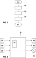
Figur 2 ist ein Ablaufdiagramm eines erfindungsgemäßen Verfahrens als Blockschaltbild dargestellt. Das Verfahren beginnt mit einer Ermittlung 210 einer Information für den Fahrer, insbesondere mittels des Steuergeräts 20, wobei die Information beispielsweise einen Navigations- und/oder einen Warnhinweis umfasst. Beispielsweise wird mittels des Steuergeräts 20 eine Navigationssoftware ausgeführt, welche einen Navigationshinweis zur Führung des Zweirads entlang einer berechneten Fahrtroute von einem Startort zu einem Zielort ermittelt, beispielsweise wird ein Abbiegehinweis ermittelt. Anschließend wird im Schritt 220 eine mechanische rechte Schwingung am rechten Lenkergriff 110a und/oder eine mechanische linke Schwingung am linken Lenkergriff 110b in Abhängigkeit der ermittelten Information erzeugt. Beispielsweise wird eine rechte Schwingung am rechten Lenkergriff 110a zur Anzeige eines Abbiegehinweises "rechts abbiegen" oder eine linke Schwingung am linken Lenkergriff 110b zur Anzeige eines Abbiegehinweises "links abbiegen" erzeugt. Dadurch kann ein Fahrer des Zweirads 10 seine Aufmerksamkeit weiterhin auf eine visuelle Erfassung der Umgebung richten. Mit anderen Worten wird der Fahrer nicht visuell durch eine Überprüfung beispielsweise einer visuellen Anzeige an einem Display des Steuergeräts 20 abgelenkt, wodurch beispielsweise Unfälle mit anderen Fahrzeugen und/oder Hindernissen resultieren können. Die im Schritt 220 erzeugte rechte Schwingung und/oder die erzeugte linke Schwingung weisen eine unterschiedliche Hauptschwingungsrichtung und/oder wenigstens eine unterschiedliche vorgegebene Schwingungsfrequenz auf. Es ist vorzugsweise vorgesehen, dass ein Winkel zwischen der Hauptschwingungsrichtung der rechten Schwingung und der Hauptschwingungsrichtung 90° beträgt. Beispielsweise weist der rechte Lenkergriff 110a eine verstärkte Schwingfähigkeit in Längsrichtung 31 des Zweirads 10 und der linke Lenkergriff 110b eine verstärkte Schwingfähigkeit in Querrichtung 32 des Zweirads 10 oder in Richtung 33 der Hochachse des Zweirads auf. Dadurch kann der Zweiradfahrer trotz einer möglichen Übertragung der Schwingung auf die andere Lenkerseite durch den Lenker beziehungsweise die Lenkstange die ermittelte Information klar identifizieren, da durch die erzeugte Schwingung nur ein Lenkergriff spürbar schwingt. Alternativ oder zusätzlich zur rechten und/oder linken Schwingung in unterschiedlichen Hauptschwingungsrichtungen kann es, wie oben beschrieben, vorgesehen sein, dass die rechte Schwingung und/oder die erzeugte linke Schwingung wenigstens eine unterschiedliche vorgegebene Schwingungsfrequenz aufweisen. Beispielsweise wird am rechten Lenkergriff 110a eine rechte Schwingung mit einer höheren Schwingungsfrequenz als der linken Schwingung am linken Lenkergriff 110b erzeugt. Es kann optional in einem weiteren Verfahrensschritt 230 vorgesehen sein, dass eine Anpassung der vorgegebenen Schwingungsfrequenz der rechten Schwingung und/oder der linken Schwingung in Abhängigkeit der ermittelten Information durchgeführt wird. Beispielsweise kann eine zunehmende Schwingungsfrequenz an einem rechten Lenkergriff als Information einen Abbiegehinweis oder einen eingehenden Anruf an einem durch eine Funkverbindung, beispielsweise eine Bluetooth-Funkverbindung, verbundenen Telefon repräsentieren. Durch die im Schritt 230 erfolgte Änderung der vorgegebenen Schwingungsfrequenz kann des Weiteren eine Position einer maximalen Amplitude der rechten Schwingung und/oder der linken Schwingung entlang einer jeweiligen Hauptausdehnungsrichtung des jeweiligen Lenkergriffs 110a, 110b angepasst werden. - In
Figur 3 ist ein Steuergerät 20 dargestellt. Das Steuergerät 20 erfasst optional Ortskoordinaten, beispielsweise durch einen Sensor 301 zu einem globalen Navigationssatellitensystem, eine Geschwindigkeit des Zweirads 10 mittels eines Geschwindigkeitssensors 302 und/oder einen Abstand zwischen dem Zweirad 10 und Objekten in der Umgebung mittels eines Abstandssensors 303, wobei der Abstandssensor 303 beispielsweise eine Kamera oder ein Ultraschallsensor sein kann. Das Steuergerät 20 ermittelt mittels der Recheneinheit 310 eine Information. Die Information wird insbesondere in Abhängigkeit der erfassten Ortskoordinaten, der erfassten Geschwindigkeit und/oder der erfassten Abstände ermittelt, wobei die Information bevorzugt ein Navigationshinweis und/oder ein Warnhinweis ist. Das Steuergerät 20 steuert anschließend in Abhängigkeit der ermittelten Information mindestens einen Aktor 320, welcher am Lenker des Zweirads 10 angeordnet ist, zur Erzeugung einer rechten und/oder linken Schwingung beziehungsweise Vibration an. Dieser Aktor ist beispielsweise in dem rechten Lenkergriff 110a und/oder dem linken Lenkergriff 110b und/oder in einer Vibrationsvorrichtung angeordnet. Es kann vorgesehen sein, dass sowohl der rechte Lenkergriff 110a als auch der linke Lenkergriff 110b jeweils einen in Abhängigkeit der ermittelten Information ansteuerbaren Aktor 320 aufweisen. Das Steuergerät 20 kann darüber hinaus mindestens einen weiteren Aktor 330 in Abhängigkeit der ermittelten Information ansteuern, beispielsweise können durch die Ansteuerung von mindestens zwei Aktoren zwei unterschiedliche Schwingungsfrequenzen gleichzeitig erzeugt werden. Es kann vorgesehen sein, dass die ermittelte Information beispielsweise auch auf einem Display 340 des Steuergeräts 20 angezeigt wird. - In
Figur 4 ist ein Lenker 100 eines Zweirads 10 beziehungsweise eine Lenkstange 440 mit einem rechten Lenkergriff 110a und einem linken Lenkergriff 110b dargestellt. Der Lenker 100 beziehungsweise die Lenkstange 440 ist mittels eines Vorbaus 430 an dem Zweirad 10 fixiert. An dem Lenker 100 ist des Weiteren eine Halterung 21 für das Steuergerät 20 sowie das Steuergerät 20 mit einem Display dargestellt. An oder in der Halterung 21 des Steuergeräts 21 ist der Aktor 320 angeordnet, welcher dazu eingerichtet ist, eine Anregungsschwingung mit einer Anregungsfrequenz in Abhängigkeit der ermittelten Information zu erzeugen und diese Anregungsschwingung auf den Lenker 100 beziehungsweise die Lenkstange 440 zu übertragen. Der Aktor 320 kann alternativ an oder in einer separaten Vibrationsvorrichtung angeordnet sein, welche beispielsweise am Lenker 100 beziehungsweise an dem Vorbau 430 angeordnet wird. Der rechte Lenkergriff 110a und der linke Lenkergriff 110b sind ferner in unterschiedlichen Hauptschwingungsrichtungen 410 und 420 verstärkt schwingfähig. Dies wird in diesem Ausführungsbeispiel dadurch erreicht, dass der rechte Lenkergriff 110a eine in der Hauptschwingungsrichtung 410 schwingbar gelagerte Resonanzmasse 111 und der linke Lenkergriff 110b eine in der Hauptschwingungsrichtung 420 schwingbar gelagerte Resonanzmasse 112 mit einer aufweisen. Die Resonanzmassen weisen unterschiedliche Massen beziehungsweise Gewichte und damit unterschiedliche Resonanzfrequenzen auf. Die Resonanzmassen 111 und 112 sind jeweils im Inneren des rechten Lenkergriffs 110a und/oder des linken Lenkergriffs 110b angeordnet. Mit anderen Worten ist in diesem Ausführungsbeispiel die Resonanzmasse 111 des rechten Lenkergriffs 110a und/oder die Resonanzmasse 112 des linken Lenkergriffs 110b bei der Montage in einem innerhalb der Lenkstange 440 beziehungsweise des Lenkrohres liegenden Hohlraum 450 angeordnet. Der Aktor 320 erzeugt eine Anregungsschwingung mit einer Anregungsfrequenz in Abhängigkeit der ermittelten Information, wodurch eine verstärkte rechte Schwingung der Resonanzmasse 111 des rechten Lenkergriffs 110a und/oder eine verstärke linke Schwingung der Resonanzmasse 112 des linken Lenkergriffs 110a in die jeweilige Hauptschwingungsrichtung des jeweiligen Lenkergriffs 110a und/oder 110b verursacht wird. Die rechte Schwingung der Resonanzmasse 111 des rechten Lenkergriffs 110a wird an eine Grifffläche 113 des rechten Lenkergriffs 110a und/oder die linke Schwingung der Resonanzmasse 112 wird an eine Grifffläche 114 des linken Lenkergriffs 110a übertragen, wodurch die rechte Schwingung und/oder die linke Schwingung für den Fahrer des Zweirads wahrnehmbar und klar identifizierbar erzeugt wird. - Alternativ zur Anordnung des Aktors 320 an einer Halterung des Steuergeräts 320 gemäß
Figur 4 können der rechte Lenkergriff 110a und der linken Lenkergriff 110b jeweils einen Aktor 320 aufweisen (nicht dargestellt), wobei der Aktor 320 des rechten Lenkergriffs 110a dazu eingerichtet ist, gegenüber dem Aktor 320 des linken Lenkergriffs 110b in einer anderen Hauptschwingungsrichtung und/oder mit einer anderen vorgegebenen Schwingungsfrequenz zu schwingen. In diesem Ausführungsbeispiel kann es vorgesehen sein, dass der rechte Lenkergriff 110a und/oder der linke Lenkergriff 110b nur optional eine Resonanzmasse 111, 112 aufweisen. - In
Figur 5 ist ein Lenker 100 beziehungsweise eine Lenkstange 440 beziehungsweise ein Lenkerrohr dargestellt. Der Lenker 100 weist einen Hohlraum 450, wie inFigur 4 , auf. Ein erster Bereich 510 des Lenkers 100 umfasst ein erstes Material, beispielsweise Aluminium. Ein zweiter Bereich 520 des Lenkers 100 umfasst ein zweites Material, beispielsweise ein Polymer, Holz oder Kork. Optional kann zwischen dem ersten Bereich 510 und dem zweiten Bereich 520 ein Dämpfungselement 530 angeordnet sein, wobei das Dämpfungselement 530 insbesondere anisotrope Schwingungseigenschaften aufweist. Des Weiteren kann optional ein weiteres Dämpfungselement 540 zur Absorption von mechanischen Schwingungen im Hohlraum 450 des Lenkers 100 angeordnet sein. Das Dämpfungselement 540 weist ebenfalls insbesondere anisotrope Schwingungseigenschaften auf. Das am Lenker 100 angeordnete Steuergerät 20 ermittelt eine Information, beispielsweise wird ein Navigationshinweis zum Abbiegen als Information ermittelt. Die ermittelte Information kann mittels eines Kabels oder mittels einer Funkverbindung, beispielsweise mittels einer Bluetooth-Verbindung, an eine Vibrationsvorrichtung 550 übertragen werden, wobei die Vibrationsvorrichtung 550 den Aktor 320 und den optionalen Aktor 330 umfasst. Der Aktor 320 und der optionale Aktor 330 werden in Abhängigkeit der empfangenen Information angesteuert. Der Aktor 320 und der optionale Aktor 330 sind dazu eingerichtet, jeweils eine Anregungsschwingung mit einer Anregungsfrequenz auf den Lenker 100 zu übertragen, wobei sich die erzeugten Anregungsfrequenzen der Anregungsschwingung des Aktors 320 und des Aktors 330 bevorzugt unterscheiden. Die mindestens eine erzeugte Anregungsschwingung des Aktors 320 wird auf den Lenker 100 übertragen, wodurch eine rechte Schwingung an einem rechten Lenkerende 590 des Lenkers 100 und/oder eine linke Schwingung an einem linken Lenkerende 591 des Lenkers 100 resultiert. Durch die Bereiche 510 und 520 des Lenkers 100, welche unterschiedliche mechanische Eigenschaften beziehungsweise Schwingungsfähigkeiten aufweisen, resultiert eine unterschiedliche vorgegebene Schwingungsfrequenz der rechte Schwingung am rechten Lenkerende 590 und der linke Schwingung am linken Lenkerende 591. - Der optionale Aktor 330 kann dazu vorgesehen sein, eine zusätzliche Anregungsschwingung mit einer von der Anregungsschwingung des Aktors 320 unterschiedlichen Anregungsfrequenz zu erzeugen. Die Ansteuerung des Aktors 320 und/oder des optionalen Aktors 330 erfolgt in Abhängigkeit der Information. Dadurch können beispielsweise eine erste Resonanzmasse 570 und/oder eine zwei Resonanzmasse 560, welche optional im Hohlraum 450 des Lenkers 100 angeordnet sind, in Abhängigkeit der Information zu einer verstärkten Schwingung angeregt werden (nicht dargestellt). In dieser Ausführung werden die erzeugte rechte Schwingung am rechten Lenkerende 590 des Lenkers 100 und die erzeugte linke Schwingung am linken Lenkerende 591 des Lenkers 100 eine unterschiedliche vorgegebene Schwingungsfrequenz aufweisen.
- In
Figur 6 ist ein Lenker 100 beziehungsweise eine Lenkstange 440 perspektivisch dargestellt, wobei der Lenker 100 an einem linken Lenkerende 591 durch einen verjüngten und/oder elastischen Bereich 603 der Lenkerstange mindestens eine schwingfähig gelagerte Resonanzmasse 601 aufweist. In diesem Ausführungsbeispiel ausFigur 6 umfasst der Lenker 100 zwei schwingfähig gelagerte Resonanzmassen 601 und 602. Die Lenkstange 440 beziehungsweise der Lenker 100 ist in diesem Beispiel ferner einstückig und weist Aluminium als Material auf. Der Lenker 100 umfasst alternativ oder zusätzlich andere Materialien, beispielsweise ein Polymer und/oder einen Faserverbundwerkstoff. Die Resonanzmassen 601 und 602 werden beispielsweise mittels des Aktor 320 der Vibrationsvorrichtung 550, mittels des Aktor 320 der Halterung 21 des Steuergeräts 20 und/oder mittels des Aktor 320 des rechten Lenkergriffs 110a und/oder mittels des Aktor 320 des linken Lenkergriffs 110b zur linken Schwingung des Lenkerendes 591 angeregt. Beispielsweise wird zur Erzeugung ein rechter Lenkergriff 110a am rechten Lenkerende 590 des Lenkers 100 angeordnet. Die erzeugte Anregungsschwingung weißt die Resonanzfrequenz der Resonanzmasse 601 und/oder 602 auf und wird durch die Lenkstange 440 beziehungsweise den Lenker 100 von dem rechten Lenkerende 590 auf das linke Lenkerende 591 übertragen, wodurch eine deutlich wahrnehmbare linke Schwingung erzeugt wird. Dabei resultiert durch die erzeugte Anregungsschwingung des Aktors 320 mit der Resonanzfrequenz der Resonanzmasse 601 bzw. 602 keine oder nur eine gedämpfte rechte Schwingung am rechten Lenkerende 590. Der Aktor 320 ist des Weiteren dazu eingerichtet, eine Anregungsschwingung mit einer von der Resonanzfrequenz der Resonanzmasse 601 bzw. 602 unterschiedlichen Anregungsfrequenz zu erzeugen. Alternativ ist ein optionaler Aktor 330 im rechten Lenkergriff 100a angeordnet, welcher die Anregungsschwingung mit einer von der Resonanzfrequenz der Resonanzmasse 601 unterschiedlichen Anregungsfrequenz erzeugt. Die erzeugte von der Resonanzfrequenz unterschiedliche Anregungsfrequenz wird bevorzugt nicht oder nur gedämpft von dem rechten Lenkerende 590 auf das linke Lenkerende 591 übertragen. Die Dämpfung der Resonanzfrequenz und/oder der von der Resonanzfrequenz unterschiedliche Anregungsfrequenz kann beispielsweise mittels eines Dämpfungselements 530 und/oder 540 erfolgen. - In
Figur 7 ist ein rechter Lenkergriff 110a beziehungsweise linker Lenkergriff 110b dargestellt, welcher mehrere Resonanzmassen 701, 702 und 703 mit jeweils unterschiedlicher Masse beziehungsweise Gewicht und unterschiedlichen Resonanzfrequenzen aufweist. Demnach können sowohl ein rechter Lenkergriff 110a als auch ein linker Lenkergriff 110b (inFigur 7 nicht dargestellt) jeweils mehrere Resonanzmassen 701, 702 und 703 mit jeweils unterschiedlicher Masse und/oder mit unterschiedlichen Resonanzfrequenzen und/oder mit einer rechten oder linken Schwingungsrichtung aufweisen. Alternativ können die Resonanzmassen 701, 702 und 703 mit jeweils unterschiedlicher Masse und/oder mit unterschiedlichen Resonanzfrequenzen und/oder mit einer rechten oder linken Schwingungsrichtung in dem Lenkerrohr beziehungsweise der Lenkstange 440 des Lenkers 100 angeordnet sein. Durch die Anpassung 230 der Anregungsfrequenz der Anregungsschwingung des Aktors 320 in Abhängigkeit der Information kann jede der Resonanzmassen 701, 702 und 703 beispielsweise zu einer rechten Schwingung des rechten Lenkergriffs 110a angeregt werden, wobei sich die (vorgegebene) Schwingungsfrequenz der rechten Schwingung entsprechend verändert. Durch die Anpassung 230 der Anregungsfrequenz der Anregungsschwingung des Aktors 320 können also nacheinander die Resonanzmassen 701, 702 und 703 zu einer rechten Schwingung angeregt werden, wodurch die Position (x1, x2, x3) der maximalen Amplitude der rechten Schwingung verändert wird. Beispielsweise werden die Resonanzmassen 701, 702 und 703 nacheinander von links nach rechts und optional wiederholt durch die Anpassung 230 der Anregungsfrequenz der Anregungsschwingung des Aktors 320 zur rechten Schwingung angeregt, wenn als Information eine Abbiegehinweis nach rechts ermittelte wurde. Demnach kann die von dem Fahrer wahrnehmbare maximale Amplitude der rechten Schwingung von der Position x1 zu der Position x2 und zu der Position x3 verändert werden beziehungsweise wandern. Analog kann durch die Anpassung 230 der Anregungsfrequenz der Anregungsschwingung des Aktors 320 nacheinander die Resonanzmassen 701, 702 und 703 zu einer linken Schwingung angeregt werden, wodurch die Position (x1, x2, x3) der maximalen Amplitude der linken Schwingung verändert wird. Beispielsweise werden die Resonanzmassen 701, 702 und 703 nacheinander von rechts nach links und optional wiederholt durch die Anpassung 230 der Anregungsfrequenz der Anregungsschwingung des Aktors 320 zur linken Schwingung angeregt, wenn als Information eine Abbiegehinweis nach links ermittelte wurde.
Claims (11)
- Verfahren zur haptischen Signalerzeugung für einen Fahrer eines Zweirads (10), wobei das Zweirad (10) einen Lenker (100) aufweist, umfassend die Verfahrensschritte• Ermittlung (210) einer Information für den Fahrer, insbesondere eines Navigations- und/oder eines Warnhinweises,• Erzeugung (220) mindestens einer erzeugbaren mechanischen rechten Schwingung an einem rechten Lenkergriff (110a) des Lenkers (100) und/oder einer erzeugbaren mechanischen linken Schwingung an einem linken Lenkergriff (110b) des Lenkers (100) in Abhängigkeit der ermittelten Information, wobei die erzeugbare rechte Schwingung und die erzeugbare linke Schwingung wenigstens eine unterschiedliche vorgegebene Schwingungsfrequenz aufweisen, und• Anpassung (230) der vorgegebenen Schwingungsfrequenz der rechten Schwingung und/oder der linken Schwingung in Abhängigkeit der ermittelten Information,dadurch gekennzeichnet, dass
die Anpassung (230) der vorgegebenen Schwingungsfrequenz eine Position (x1, x2, x3) einer maximalen Amplitude der rechten Schwingung und/oder der linken Schwingung entlang einer jeweiligen Hauptausdehnungsrichtung des jeweiligen Lenkergriffs (110a, 110b) anpasst. - Verfahren nach Anspruch 1, dadurch gekennzeichnet, dass ein Winkel zwischen der Hauptschwingungsrichtung der rechten Schwingung und der Hauptschwingungsrichtung der linken Schwingung einen Betrag größer 45° aufweist, wobei der Winkel insbesondere 90° beträgt.
- Zweirad (10) mit einem Lenker (100), wobei der Lenker einen rechten Lenkergriff (110a) und einen linken Lenkergriff (110b) aufweist, wobei die Lenkergriffe dazu eingerichtet sind, durch ein Verfahren nach einer der Ansprüche 1-2 zu einer Schwingung mit einer vorgegebenen Schwingungsfrequenz angeregt zu werden, und wobei das Zweirad (10) ein Steuergerät (20) aufweist, wobei das Steuergerät (20) dazu eingerichtet ist, ein Verfahren nach einem der Ansprüche 1 oder 2 zur Steuerung des Zweirads (10) durchzuführen.
- Zweirad nach Anspruch 3, dadurch gekennzeichnet, dass der rechte Lenkergriff (110a) und der linke Lenkergriff (110b) jeweils mindestens eine schwingbar gelagerte Resonanzmasse (111, 112, 701, 702, 703) aufweist, insbesondere umfasst der rechte Lenkergriff (110a) und der linke Lenkergriff (110b) jeweils wenigstens zwei Resonanzmassen (111, 112, 701, 702, 703) mit unterschiedlicher Resonanzfrequenz.
- Zweirad nach Anspruch 3 oder 4, dadurch gekennzeichnet, dass der rechte Lenkergriff (110a) und der linke Lenkergriff (110b) jeweils ein Dämpfungselement (530, 540) zur Dämpfung einer mechanischen Schwingung aufweist, wobei das Dämpfungselement (530, 540) insbesondere ein anisotropes Material umfasst.
- Zweirad nach einem der Ansprüche 3 bis 5, dadurch gekennzeichnet, dass der rechte Lenkergriff (110a) und der linke Lenkergriff (110b) jeweils in einer Raumrichtung senkrecht zur Hauptausdehnungsrichtung des jeweiligen Lenkergriffs (110a, 110b) eine höhere Steifigkeit als in einer davon abweichenden Raumrichtung senkrecht zur Hauptausdehnungsrichtung des jeweiligen Lenkergriffs (110a, 110b) aufweist, wobei die Raumrichtungen zueinander insbesondere einen Winkel mit einem Betrag größer 45° einschließen, bevorzugt beträgt der Winkel zwischen der Raumrichtung mit der höheren Steifigkeit und der Raumrichtung mit der niedrigeren Steifigkeit 90°.
- Zweirad nach einem der Ansprüche 3 bis 6, dadurch gekennzeichnet, dass der rechte Lenkergriff (110a) und der linke Lenkergriff (110b) jeweils einen elektromechanischen Aktor (320, 330) aufweist, wobei der Aktor (320, 330) dazu eingerichtet ist, eine mechanische Anregungsschwingung in der Hauptschwingungsrichtung und/oder mit der vorgegebenen Schwingungsfrequenz zu erzeugen.
- Zweirad nach einem der Ansprüche 3 bis 7, dadurch gekennzeichnet, dass der Lenker (100)• an einem rechten Lenkerende (590) und an einem linken Lenkerende (591) mindestens eine asymmetrische mechanische Eigenschaft aufweist, und• Lenkerende und/oder am linken Lenkerende mindestens eine Resonanzmasse (560, 570, 601, 602) aufweist.
- Zweirad nach Anspruch 8, dadurch gekennzeichnet, dass der Lenker (100) eine mechanische Steifigkeit am rechten Lenkerende aufweist, welche sich in mindestens einer Raumrichtung von einer mechanischen Steifigkeit des Lenkers (100) am linken Lenkerende unterscheidet.
- Zweirad nach einem der Ansprüche 8 bis 9, dadurch gekennzeichnet, dass der Lenker am rechten Lenkerende und/oder am linken Lenkerende ein Dämpfungselement (530, 540) zur Dämpfung einer mechanischen Schwingung aufweist, wobei das Dämpfungselement (530, 540) insbesondere ein anisotropes Material umfasst.
- Zweirad nach einem der Ansprüche 8 bis 10, dadurch gekennzeichnet, dass der Lenker in einem ersten Bereich (510) ein erstes Material und in einem zweiten Bereich (520) ein zweites Material aufweist, wobei das erste Material und des zweite Material eine voneinander unterschiedliche Masse aufweisen.
Applications Claiming Priority (1)
| Application Number | Priority Date | Filing Date | Title |
|---|---|---|---|
| DE102018209048.3A DE102018209048B4 (de) | 2018-06-07 | 2018-06-07 | Verfahren zur haptischen Signalerzeugung für einen Fahrer eines Zweirads, Lenkergriff, Vibrationsvorrichtung, Lenker, Steuergerät und Zweirad |
Publications (3)
| Publication Number | Publication Date |
|---|---|
| EP3588005A2 EP3588005A2 (de) | 2020-01-01 |
| EP3588005A3 EP3588005A3 (de) | 2020-03-18 |
| EP3588005B1 true EP3588005B1 (de) | 2024-04-03 |
Family
ID=66676320
Family Applications (1)
| Application Number | Title | Priority Date | Filing Date |
|---|---|---|---|
| EP19177190.6A Active EP3588005B1 (de) | 2018-06-07 | 2019-05-29 | Verfahren zur haptischen signalerzeugung für einen fahrer eines zweirads, und zweirad |
Country Status (2)
| Country | Link |
|---|---|
| EP (1) | EP3588005B1 (de) |
| DE (1) | DE102018209048B4 (de) |
Families Citing this family (4)
| Publication number | Priority date | Publication date | Assignee | Title |
|---|---|---|---|---|
| JP7170125B2 (ja) * | 2019-03-29 | 2022-11-11 | 本田技研工業株式会社 | 鞍乗り型車両の運転支援装置 |
| IT202100009584A1 (it) * | 2021-04-16 | 2022-10-16 | Verde Stilnovo S R L | Sistema di ausilio alla guida e veicolo a due ruote con sistema di ausilio alla guida |
| WO2023012813A1 (en) * | 2021-08-04 | 2023-02-09 | Tvs Motor Company Limited | A navigation system, a control unit and a method of navigation for a motor vehicle |
| US12151770B2 (en) * | 2021-12-22 | 2024-11-26 | Zero Motorcycles, Inc. | Switchgear for vehicle and vehicle including switchgear |
Family Cites Families (6)
| Publication number | Priority date | Publication date | Assignee | Title |
|---|---|---|---|---|
| WO2011125478A1 (ja) * | 2010-04-02 | 2011-10-13 | シャープ株式会社 | 車両用警告装置 |
| DE202015102562U1 (de) | 2015-05-19 | 2015-07-23 | Boreal Bikes Incorporated/Les Bicyclettes Boreal Incorporée | Navigationsgriff zum Befestigen an einem Lenkerrohr |
| DE102015215527A1 (de) * | 2015-08-14 | 2017-02-16 | Robert Bosch Gmbh | Verfahren und Vorrichtung zur Ansteuerung wenigstens eines Lenkergriffs eines Zweirads |
| DE102015219698A1 (de) * | 2015-10-12 | 2017-04-13 | Bayerische Motoren Werke Aktiengesellschaft | Haptische Benutzerschnittstelle für ein Fahrzeug |
| DE102015226046A1 (de) * | 2015-12-18 | 2017-06-22 | Bayerische Motoren Werke Aktiengesellschaft | Verfahren zur Erzeugung einer haptischen Signalisierung an einem manuellen Steuermittel eines Fahrzeugs |
| US11059495B2 (en) * | 2016-09-12 | 2021-07-13 | Sony Corporation | Information presentation apparatus, steering apparatus, and information presentation method |
-
2018
- 2018-06-07 DE DE102018209048.3A patent/DE102018209048B4/de active Active
-
2019
- 2019-05-29 EP EP19177190.6A patent/EP3588005B1/de active Active
Also Published As
| Publication number | Publication date |
|---|---|
| DE102018209048B4 (de) | 2022-09-15 |
| EP3588005A2 (de) | 2020-01-01 |
| EP3588005A3 (de) | 2020-03-18 |
| DE102018209048A1 (de) | 2019-12-12 |
Similar Documents
| Publication | Publication Date | Title |
|---|---|---|
| EP3588005B1 (de) | Verfahren zur haptischen signalerzeugung für einen fahrer eines zweirads, und zweirad | |
| DE102016216590A1 (de) | Verfahren, Vorrichtung und Computerprogramm zur Erzeugung und Übermittlung einer Fahrerinformation | |
| DE102016225489B4 (de) | Verfahren zur Einstellung einer Komponente eines Zweirads auf einen definierten Betriebszustand und Vorrichtungen | |
| EP3552941A1 (de) | Fahrrad, fahrradbaugruppe und verfahren | |
| EP3597520B1 (de) | Lenkergriff mit schwingungserzeuger und zweirad mit diesem lenkergriff | |
| DE102012113038B4 (de) | Verfahren zur Geräuschoptimierung | |
| EP3390191B1 (de) | Verfahren zur erzeugung einer haptischen signalisierung an einem manuellen steuermittel eines fahrzeugs | |
| DE102008046866A1 (de) | Verfahren zur Einstellung eines Zusatzlenkmoments in einer Lenkeinrichtung eines Kraftfahrzeugs zur Erzeugung einer haptischen Lenkradwarnung beim Spurverlassen | |
| DE102017210966A1 (de) | Verfahren und Vorrichtung zum Betreiben eines Kraftfahrzeugs mit einem Lenksystem für die Identifikation von Fahrereingriffen | |
| EP2689996A1 (de) | Verfahren und Vorrichtung zur Steuerung einer Dämpfung eines Fahrrads | |
| EP3645378B1 (de) | Motorradlenker mit aktiver schwingungsdämpfung | |
| DE102015107386B4 (de) | Bedienanordnung für eine Lenkhandhabe eines Kraftfahrzeugs, Lenkhandhabe sowie Kraftfahrzeug | |
| EP3418175B1 (de) | Steuergerät und steuerungsverfahren für einen antriebsmotor eines zweirads | |
| DE10209206A1 (de) | Warnvorrichtung | |
| DE102012113035B4 (de) | Vorrichtung zur Geräuschoptimierung und Verfahren zum Betreiben einer Vorrichtung zur Geräuschoptimierung | |
| DE102013201289B4 (de) | Verfahren zum Erkennen eines Schwingens in einem Schienenfahrzeug | |
| EP4541693A1 (de) | Verfahren zum betreiben eines steer-by-wire-lenksystems eines kraftfahrzeugs, steer-by-wire-lenksystem sowie kraftfahrzeug | |
| DE102016122843A1 (de) | Verfahren zur Schwingungsreduzierung in Lenksystemen | |
| DE102009015416B4 (de) | Verfahren zur Warnung des Fahrers | |
| EP3342697B1 (de) | Verfahren zur reduzierung des kick-back effekts bei elektrofahrrädern und elektrofahrrad | |
| EP3387645A1 (de) | System und verfahren zur aktiven lärmkompensation bei krafträdern sowie kraftrad mit einem system zur aktiven lärmkompensation | |
| DE102006052368A1 (de) | System und Verfahren zur Fahrspurüberwachung | |
| DE102011087669B4 (de) | Kraftfahrzeugvorrichtung und Verfahren zur Signalgebung | |
| DE102018213287A1 (de) | Verfahren zum Betreiben eines elektromotorisch antreibbaren Fahrzeugs, elektromotorisch antreibbares Fahrzeug | |
| DE102005021415A1 (de) | Verfahren und Vorrichtung zur Dämpfung von Längsschwingungen von Flüssigkeiten in Fahrzeugtransportbehältern |
Legal Events
| Date | Code | Title | Description |
|---|---|---|---|
| PUAI | Public reference made under article 153(3) epc to a published international application that has entered the european phase |
Free format text: ORIGINAL CODE: 0009012 |
|
| STAA | Information on the status of an ep patent application or granted ep patent |
Free format text: STATUS: THE APPLICATION HAS BEEN PUBLISHED |
|
| AK | Designated contracting states |
Kind code of ref document: A2 Designated state(s): AL AT BE BG CH CY CZ DE DK EE ES FI FR GB GR HR HU IE IS IT LI LT LU LV MC MK MT NL NO PL PT RO RS SE SI SK SM TR |
|
| AX | Request for extension of the european patent |
Extension state: BA ME |
|
| PUAL | Search report despatched |
Free format text: ORIGINAL CODE: 0009013 |
|
| AK | Designated contracting states |
Kind code of ref document: A3 Designated state(s): AL AT BE BG CH CY CZ DE DK EE ES FI FR GB GR HR HU IE IS IT LI LT LU LV MC MK MT NL NO PL PT RO RS SE SI SK SM TR |
|
| AX | Request for extension of the european patent |
Extension state: BA ME |
|
| RIC1 | Information provided on ipc code assigned before grant |
Ipc: B60Q 9/00 20060101ALI20200207BHEP Ipc: B62K 21/26 20060101ALI20200207BHEP Ipc: G01C 21/36 20060101ALI20200207BHEP Ipc: G01C 21/26 20060101AFI20200207BHEP Ipc: B60W 50/16 20200101ALI20200207BHEP Ipc: B62K 21/12 20060101ALI20200207BHEP |
|
| RAP1 | Party data changed (applicant data changed or rights of an application transferred) |
Owner name: ROBERT BOSCH GMBH |
|
| STAA | Information on the status of an ep patent application or granted ep patent |
Free format text: STATUS: REQUEST FOR EXAMINATION WAS MADE |
|
| 17P | Request for examination filed |
Effective date: 20200918 |
|
| RBV | Designated contracting states (corrected) |
Designated state(s): AL AT BE BG CH CY CZ DE DK EE ES FI FR GB GR HR HU IE IS IT LI LT LU LV MC MK MT NL NO PL PT RO RS SE SI SK SM TR |
|
| STAA | Information on the status of an ep patent application or granted ep patent |
Free format text: STATUS: EXAMINATION IS IN PROGRESS |
|
| 17Q | First examination report despatched |
Effective date: 20210831 |
|
| REG | Reference to a national code |
Ref legal event code: R079 Free format text: PREVIOUS MAIN CLASS: G01C0021260000 Ref country code: DE Ref legal event code: R079 Ref document number: 502019010941 Country of ref document: DE Free format text: PREVIOUS MAIN CLASS: G01C0021260000 Ipc: B60Q0009000000 |
|
| RIC1 | Information provided on ipc code assigned before grant |
Ipc: G01C 21/36 20060101ALI20230523BHEP Ipc: G01C 21/26 20060101ALI20230523BHEP Ipc: B62M 6/55 20100101ALI20230523BHEP Ipc: B62K 21/26 20060101ALI20230523BHEP Ipc: B62K 21/14 20060101ALI20230523BHEP Ipc: B62K 21/12 20060101ALI20230523BHEP Ipc: B62J 50/22 20200101ALI20230523BHEP Ipc: B60W 50/16 20200101ALI20230523BHEP Ipc: B60Q 9/00 20060101AFI20230523BHEP |
|
| GRAP | Despatch of communication of intention to grant a patent |
Free format text: ORIGINAL CODE: EPIDOSNIGR1 |
|
| STAA | Information on the status of an ep patent application or granted ep patent |
Free format text: STATUS: GRANT OF PATENT IS INTENDED |
|
| INTG | Intention to grant announced |
Effective date: 20231130 |
|
| GRAS | Grant fee paid |
Free format text: ORIGINAL CODE: EPIDOSNIGR3 |
|
| GRAA | (expected) grant |
Free format text: ORIGINAL CODE: 0009210 |
|
| STAA | Information on the status of an ep patent application or granted ep patent |
Free format text: STATUS: THE PATENT HAS BEEN GRANTED |
|
| AK | Designated contracting states |
Kind code of ref document: B1 Designated state(s): AL AT BE BG CH CY CZ DE DK EE ES FI FR GB GR HR HU IE IS IT LI LT LU LV MC MK MT NL NO PL PT RO RS SE SI SK SM TR |
|
| REG | Reference to a national code |
Ref country code: GB Ref legal event code: FG4D Free format text: NOT ENGLISH |
|
| REG | Reference to a national code |
Ref country code: CH Ref legal event code: EP |
|
| REG | Reference to a national code |
Ref country code: DE Ref legal event code: R096 Ref document number: 502019010941 Country of ref document: DE |
|
| REG | Reference to a national code |
Ref country code: IE Ref legal event code: FG4D Free format text: LANGUAGE OF EP DOCUMENT: GERMAN |
|
| REG | Reference to a national code |
Ref country code: LT Ref legal event code: MG9D |
|
| REG | Reference to a national code |
Ref country code: NL Ref legal event code: MP Effective date: 20240403 |
|
| PG25 | Lapsed in a contracting state [announced via postgrant information from national office to epo] |
Ref country code: NL Free format text: LAPSE BECAUSE OF FAILURE TO SUBMIT A TRANSLATION OF THE DESCRIPTION OR TO PAY THE FEE WITHIN THE PRESCRIBED TIME-LIMIT Effective date: 20240403 |
|
| PG25 | Lapsed in a contracting state [announced via postgrant information from national office to epo] |
Ref country code: NL Free format text: LAPSE BECAUSE OF FAILURE TO SUBMIT A TRANSLATION OF THE DESCRIPTION OR TO PAY THE FEE WITHIN THE PRESCRIBED TIME-LIMIT Effective date: 20240403 |
|
| PG25 | Lapsed in a contracting state [announced via postgrant information from national office to epo] |
Ref country code: IS Free format text: LAPSE BECAUSE OF FAILURE TO SUBMIT A TRANSLATION OF THE DESCRIPTION OR TO PAY THE FEE WITHIN THE PRESCRIBED TIME-LIMIT Effective date: 20240803 |
|
| PG25 | Lapsed in a contracting state [announced via postgrant information from national office to epo] |
Ref country code: BG Free format text: LAPSE BECAUSE OF FAILURE TO SUBMIT A TRANSLATION OF THE DESCRIPTION OR TO PAY THE FEE WITHIN THE PRESCRIBED TIME-LIMIT Effective date: 20240403 |
|
| PG25 | Lapsed in a contracting state [announced via postgrant information from national office to epo] |
Ref country code: HR Free format text: LAPSE BECAUSE OF FAILURE TO SUBMIT A TRANSLATION OF THE DESCRIPTION OR TO PAY THE FEE WITHIN THE PRESCRIBED TIME-LIMIT Effective date: 20240403 Ref country code: FI Free format text: LAPSE BECAUSE OF FAILURE TO SUBMIT A TRANSLATION OF THE DESCRIPTION OR TO PAY THE FEE WITHIN THE PRESCRIBED TIME-LIMIT Effective date: 20240403 |
|
| PG25 | Lapsed in a contracting state [announced via postgrant information from national office to epo] |
Ref country code: GR Free format text: LAPSE BECAUSE OF FAILURE TO SUBMIT A TRANSLATION OF THE DESCRIPTION OR TO PAY THE FEE WITHIN THE PRESCRIBED TIME-LIMIT Effective date: 20240704 |
|
| PG25 | Lapsed in a contracting state [announced via postgrant information from national office to epo] |
Ref country code: PT Free format text: LAPSE BECAUSE OF FAILURE TO SUBMIT A TRANSLATION OF THE DESCRIPTION OR TO PAY THE FEE WITHIN THE PRESCRIBED TIME-LIMIT Effective date: 20240805 |
|
| PG25 | Lapsed in a contracting state [announced via postgrant information from national office to epo] |
Ref country code: ES Free format text: LAPSE BECAUSE OF FAILURE TO SUBMIT A TRANSLATION OF THE DESCRIPTION OR TO PAY THE FEE WITHIN THE PRESCRIBED TIME-LIMIT Effective date: 20240403 |
|
| PG25 | Lapsed in a contracting state [announced via postgrant information from national office to epo] |
Ref country code: CZ Free format text: LAPSE BECAUSE OF FAILURE TO SUBMIT A TRANSLATION OF THE DESCRIPTION OR TO PAY THE FEE WITHIN THE PRESCRIBED TIME-LIMIT Effective date: 20240403 |
|
| PG25 | Lapsed in a contracting state [announced via postgrant information from national office to epo] |
Ref country code: PL Free format text: LAPSE BECAUSE OF FAILURE TO SUBMIT A TRANSLATION OF THE DESCRIPTION OR TO PAY THE FEE WITHIN THE PRESCRIBED TIME-LIMIT Effective date: 20240403 |
|
| PG25 | Lapsed in a contracting state [announced via postgrant information from national office to epo] |
Ref country code: LV Free format text: LAPSE BECAUSE OF FAILURE TO SUBMIT A TRANSLATION OF THE DESCRIPTION OR TO PAY THE FEE WITHIN THE PRESCRIBED TIME-LIMIT Effective date: 20240403 |
|
| PG25 | Lapsed in a contracting state [announced via postgrant information from national office to epo] |
Ref country code: PT Free format text: LAPSE BECAUSE OF FAILURE TO SUBMIT A TRANSLATION OF THE DESCRIPTION OR TO PAY THE FEE WITHIN THE PRESCRIBED TIME-LIMIT Effective date: 20240805 Ref country code: PL Free format text: LAPSE BECAUSE OF FAILURE TO SUBMIT A TRANSLATION OF THE DESCRIPTION OR TO PAY THE FEE WITHIN THE PRESCRIBED TIME-LIMIT Effective date: 20240403 Ref country code: NO Free format text: LAPSE BECAUSE OF FAILURE TO SUBMIT A TRANSLATION OF THE DESCRIPTION OR TO PAY THE FEE WITHIN THE PRESCRIBED TIME-LIMIT Effective date: 20240703 Ref country code: LV Free format text: LAPSE BECAUSE OF FAILURE TO SUBMIT A TRANSLATION OF THE DESCRIPTION OR TO PAY THE FEE WITHIN THE PRESCRIBED TIME-LIMIT Effective date: 20240403 Ref country code: IS Free format text: LAPSE BECAUSE OF FAILURE TO SUBMIT A TRANSLATION OF THE DESCRIPTION OR TO PAY THE FEE WITHIN THE PRESCRIBED TIME-LIMIT Effective date: 20240803 Ref country code: HR Free format text: LAPSE BECAUSE OF FAILURE TO SUBMIT A TRANSLATION OF THE DESCRIPTION OR TO PAY THE FEE WITHIN THE PRESCRIBED TIME-LIMIT Effective date: 20240403 Ref country code: GR Free format text: LAPSE BECAUSE OF FAILURE TO SUBMIT A TRANSLATION OF THE DESCRIPTION OR TO PAY THE FEE WITHIN THE PRESCRIBED TIME-LIMIT Effective date: 20240704 Ref country code: FI Free format text: LAPSE BECAUSE OF FAILURE TO SUBMIT A TRANSLATION OF THE DESCRIPTION OR TO PAY THE FEE WITHIN THE PRESCRIBED TIME-LIMIT Effective date: 20240403 Ref country code: ES Free format text: LAPSE BECAUSE OF FAILURE TO SUBMIT A TRANSLATION OF THE DESCRIPTION OR TO PAY THE FEE WITHIN THE PRESCRIBED TIME-LIMIT Effective date: 20240403 Ref country code: CZ Free format text: LAPSE BECAUSE OF FAILURE TO SUBMIT A TRANSLATION OF THE DESCRIPTION OR TO PAY THE FEE WITHIN THE PRESCRIBED TIME-LIMIT Effective date: 20240403 Ref country code: BG Free format text: LAPSE BECAUSE OF FAILURE TO SUBMIT A TRANSLATION OF THE DESCRIPTION OR TO PAY THE FEE WITHIN THE PRESCRIBED TIME-LIMIT Effective date: 20240403 Ref country code: RS Free format text: LAPSE BECAUSE OF FAILURE TO SUBMIT A TRANSLATION OF THE DESCRIPTION OR TO PAY THE FEE WITHIN THE PRESCRIBED TIME-LIMIT Effective date: 20240703 |
|
| REG | Reference to a national code |
Ref country code: CH Ref legal event code: PL |
|
| REG | Reference to a national code |
Ref country code: DE Ref legal event code: R097 Ref document number: 502019010941 Country of ref document: DE |
|
| PG25 | Lapsed in a contracting state [announced via postgrant information from national office to epo] |
Ref country code: DK Free format text: LAPSE BECAUSE OF FAILURE TO SUBMIT A TRANSLATION OF THE DESCRIPTION OR TO PAY THE FEE WITHIN THE PRESCRIBED TIME-LIMIT Effective date: 20240403 |
|
| PG25 | Lapsed in a contracting state [announced via postgrant information from national office to epo] |
Ref country code: LU Free format text: LAPSE BECAUSE OF NON-PAYMENT OF DUE FEES Effective date: 20240529 |
|
| PG25 | Lapsed in a contracting state [announced via postgrant information from national office to epo] |
Ref country code: EE Free format text: LAPSE BECAUSE OF FAILURE TO SUBMIT A TRANSLATION OF THE DESCRIPTION OR TO PAY THE FEE WITHIN THE PRESCRIBED TIME-LIMIT Effective date: 20240403 |
|
| PG25 | Lapsed in a contracting state [announced via postgrant information from national office to epo] |
Ref country code: RO Free format text: LAPSE BECAUSE OF FAILURE TO SUBMIT A TRANSLATION OF THE DESCRIPTION OR TO PAY THE FEE WITHIN THE PRESCRIBED TIME-LIMIT Effective date: 20240403 Ref country code: SK Free format text: LAPSE BECAUSE OF FAILURE TO SUBMIT A TRANSLATION OF THE DESCRIPTION OR TO PAY THE FEE WITHIN THE PRESCRIBED TIME-LIMIT Effective date: 20240403 |
|
| PG25 | Lapsed in a contracting state [announced via postgrant information from national office to epo] |
Ref country code: SM Free format text: LAPSE BECAUSE OF FAILURE TO SUBMIT A TRANSLATION OF THE DESCRIPTION OR TO PAY THE FEE WITHIN THE PRESCRIBED TIME-LIMIT Effective date: 20240403 |
|
| PG25 | Lapsed in a contracting state [announced via postgrant information from national office to epo] |
Ref country code: SM Free format text: LAPSE BECAUSE OF FAILURE TO SUBMIT A TRANSLATION OF THE DESCRIPTION OR TO PAY THE FEE WITHIN THE PRESCRIBED TIME-LIMIT Effective date: 20240403 Ref country code: SK Free format text: LAPSE BECAUSE OF FAILURE TO SUBMIT A TRANSLATION OF THE DESCRIPTION OR TO PAY THE FEE WITHIN THE PRESCRIBED TIME-LIMIT Effective date: 20240403 Ref country code: RO Free format text: LAPSE BECAUSE OF FAILURE TO SUBMIT A TRANSLATION OF THE DESCRIPTION OR TO PAY THE FEE WITHIN THE PRESCRIBED TIME-LIMIT Effective date: 20240403 Ref country code: LU Free format text: LAPSE BECAUSE OF NON-PAYMENT OF DUE FEES Effective date: 20240529 Ref country code: EE Free format text: LAPSE BECAUSE OF FAILURE TO SUBMIT A TRANSLATION OF THE DESCRIPTION OR TO PAY THE FEE WITHIN THE PRESCRIBED TIME-LIMIT Effective date: 20240403 Ref country code: DK Free format text: LAPSE BECAUSE OF FAILURE TO SUBMIT A TRANSLATION OF THE DESCRIPTION OR TO PAY THE FEE WITHIN THE PRESCRIBED TIME-LIMIT Effective date: 20240403 Ref country code: CH Free format text: LAPSE BECAUSE OF NON-PAYMENT OF DUE FEES Effective date: 20240531 Ref country code: MC Free format text: LAPSE BECAUSE OF FAILURE TO SUBMIT A TRANSLATION OF THE DESCRIPTION OR TO PAY THE FEE WITHIN THE PRESCRIBED TIME-LIMIT Effective date: 20240403 |
|
| PLBE | No opposition filed within time limit |
Free format text: ORIGINAL CODE: 0009261 |
|
| STAA | Information on the status of an ep patent application or granted ep patent |
Free format text: STATUS: NO OPPOSITION FILED WITHIN TIME LIMIT |
|
| REG | Reference to a national code |
Ref country code: BE Ref legal event code: MM Effective date: 20240531 |
|
| 26N | No opposition filed |
Effective date: 20250106 |
|
| GBPC | Gb: european patent ceased through non-payment of renewal fee |
Effective date: 20240703 |
|
| PG25 | Lapsed in a contracting state [announced via postgrant information from national office to epo] |
Ref country code: IE Free format text: LAPSE BECAUSE OF NON-PAYMENT OF DUE FEES Effective date: 20240529 |
|
| PG25 | Lapsed in a contracting state [announced via postgrant information from national office to epo] |
Ref country code: SI Free format text: LAPSE BECAUSE OF FAILURE TO SUBMIT A TRANSLATION OF THE DESCRIPTION OR TO PAY THE FEE WITHIN THE PRESCRIBED TIME-LIMIT Effective date: 20240403 Ref country code: BE Free format text: LAPSE BECAUSE OF NON-PAYMENT OF DUE FEES Effective date: 20240531 |
|
| PG25 | Lapsed in a contracting state [announced via postgrant information from national office to epo] |
Ref country code: FR Free format text: LAPSE BECAUSE OF NON-PAYMENT OF DUE FEES Effective date: 20240603 |
|
| PG25 | Lapsed in a contracting state [announced via postgrant information from national office to epo] |
Ref country code: GB Free format text: LAPSE BECAUSE OF NON-PAYMENT OF DUE FEES Effective date: 20240703 |
|
| REG | Reference to a national code |
Ref country code: AT Ref legal event code: MM01 Ref document number: 1671932 Country of ref document: AT Kind code of ref document: T Effective date: 20240529 |
|
| PG25 | Lapsed in a contracting state [announced via postgrant information from national office to epo] |
Ref country code: AT Free format text: LAPSE BECAUSE OF NON-PAYMENT OF DUE FEES Effective date: 20240529 |
|
| PG25 | Lapsed in a contracting state [announced via postgrant information from national office to epo] |
Ref country code: SE Free format text: LAPSE BECAUSE OF FAILURE TO SUBMIT A TRANSLATION OF THE DESCRIPTION OR TO PAY THE FEE WITHIN THE PRESCRIBED TIME-LIMIT Effective date: 20240403 |
|
| PG25 | Lapsed in a contracting state [announced via postgrant information from national office to epo] |
Ref country code: CY Free format text: LAPSE BECAUSE OF FAILURE TO SUBMIT A TRANSLATION OF THE DESCRIPTION OR TO PAY THE FEE WITHIN THE PRESCRIBED TIME-LIMIT; INVALID AB INITIO Effective date: 20190529 |
|
| PGFP | Annual fee paid to national office [announced via postgrant information from national office to epo] |
Ref country code: DE Payment date: 20250716 Year of fee payment: 7 |
|
| PG25 | Lapsed in a contracting state [announced via postgrant information from national office to epo] |
Ref country code: IT Free format text: LAPSE BECAUSE OF FAILURE TO SUBMIT A TRANSLATION OF THE DESCRIPTION OR TO PAY THE FEE WITHIN THE PRESCRIBED TIME-LIMIT Effective date: 20240403 |
|
| PG25 | Lapsed in a contracting state [announced via postgrant information from national office to epo] |
Ref country code: HU Free format text: LAPSE BECAUSE OF FAILURE TO SUBMIT A TRANSLATION OF THE DESCRIPTION OR TO PAY THE FEE WITHIN THE PRESCRIBED TIME-LIMIT; INVALID AB INITIO Effective date: 20190529 |