EP3587796A1 - Éolienne à alignement automatique - Google Patents
Éolienne à alignement automatique Download PDFInfo
- Publication number
- EP3587796A1 EP3587796A1 EP18180452.7A EP18180452A EP3587796A1 EP 3587796 A1 EP3587796 A1 EP 3587796A1 EP 18180452 A EP18180452 A EP 18180452A EP 3587796 A1 EP3587796 A1 EP 3587796A1
- Authority
- EP
- European Patent Office
- Prior art keywords
- repeller
- wind
- arrangement
- repellers
- axis
- Prior art date
- Legal status (The legal status is an assumption and is not a legal conclusion. Google has not performed a legal analysis and makes no representation as to the accuracy of the status listed.)
- Withdrawn
Links
- 238000009434 installation Methods 0.000 title description 2
- 230000005484 gravity Effects 0.000 claims abstract description 37
- 230000000694 effects Effects 0.000 claims description 23
- 238000000034 method Methods 0.000 claims description 4
- 230000008901 benefit Effects 0.000 description 12
- 230000008878 coupling Effects 0.000 description 9
- 238000010168 coupling process Methods 0.000 description 9
- 238000005859 coupling reaction Methods 0.000 description 9
- 230000007423 decrease Effects 0.000 description 7
- 101150067055 minC gene Proteins 0.000 description 7
- 230000001419 dependent effect Effects 0.000 description 4
- 238000007667 floating Methods 0.000 description 4
- 238000012423 maintenance Methods 0.000 description 4
- 241001295925 Gegenes Species 0.000 description 3
- 238000013461 design Methods 0.000 description 3
- 238000005259 measurement Methods 0.000 description 3
- 230000035515 penetration Effects 0.000 description 3
- 230000002349 favourable effect Effects 0.000 description 2
- 238000010248 power generation Methods 0.000 description 2
- 230000008569 process Effects 0.000 description 2
- 230000002787 reinforcement Effects 0.000 description 2
- 229910000679 solder Inorganic materials 0.000 description 2
- 101100129500 Caenorhabditis elegans max-2 gene Proteins 0.000 description 1
- VVQNEPGJFQJSBK-UHFFFAOYSA-N Methyl methacrylate Chemical compound COC(=O)C(C)=C VVQNEPGJFQJSBK-UHFFFAOYSA-N 0.000 description 1
- 229920005372 Plexiglas® Polymers 0.000 description 1
- 230000001133 acceleration Effects 0.000 description 1
- 230000001154 acute effect Effects 0.000 description 1
- 238000004873 anchoring Methods 0.000 description 1
- 230000005540 biological transmission Effects 0.000 description 1
- 230000015572 biosynthetic process Effects 0.000 description 1
- 230000008859 change Effects 0.000 description 1
- 238000006243 chemical reaction Methods 0.000 description 1
- 238000012937 correction Methods 0.000 description 1
- 230000003247 decreasing effect Effects 0.000 description 1
- 230000005611 electricity Effects 0.000 description 1
- 230000007613 environmental effect Effects 0.000 description 1
- 230000003993 interaction Effects 0.000 description 1
- 238000004519 manufacturing process Methods 0.000 description 1
- 230000000873 masking effect Effects 0.000 description 1
- 239000000463 material Substances 0.000 description 1
- 239000000047 product Substances 0.000 description 1
- 230000009467 reduction Effects 0.000 description 1
- 230000004044 response Effects 0.000 description 1
- 239000013589 supplement Substances 0.000 description 1
- XLYOFNOQVPJJNP-UHFFFAOYSA-N water Substances O XLYOFNOQVPJJNP-UHFFFAOYSA-N 0.000 description 1
Images


Classifications
-
- F—MECHANICAL ENGINEERING; LIGHTING; HEATING; WEAPONS; BLASTING
- F03—MACHINES OR ENGINES FOR LIQUIDS; WIND, SPRING, OR WEIGHT MOTORS; PRODUCING MECHANICAL POWER OR A REACTIVE PROPULSIVE THRUST, NOT OTHERWISE PROVIDED FOR
- F03D—WIND MOTORS
- F03D1/00—Wind motors with rotation axis substantially parallel to the air flow entering the rotor
- F03D1/02—Wind motors with rotation axis substantially parallel to the air flow entering the rotor having a plurality of rotors
-
- F—MECHANICAL ENGINEERING; LIGHTING; HEATING; WEAPONS; BLASTING
- F03—MACHINES OR ENGINES FOR LIQUIDS; WIND, SPRING, OR WEIGHT MOTORS; PRODUCING MECHANICAL POWER OR A REACTIVE PROPULSIVE THRUST, NOT OTHERWISE PROVIDED FOR
- F03D—WIND MOTORS
- F03D7/00—Controlling wind motors
- F03D7/02—Controlling wind motors the wind motors having rotation axis substantially parallel to the air flow entering the rotor
- F03D7/0204—Controlling wind motors the wind motors having rotation axis substantially parallel to the air flow entering the rotor for orientation in relation to wind direction
-
- F—MECHANICAL ENGINEERING; LIGHTING; HEATING; WEAPONS; BLASTING
- F05—INDEXING SCHEMES RELATING TO ENGINES OR PUMPS IN VARIOUS SUBCLASSES OF CLASSES F01-F04
- F05B—INDEXING SCHEME RELATING TO WIND, SPRING, WEIGHT, INERTIA OR LIKE MOTORS, TO MACHINES OR ENGINES FOR LIQUIDS COVERED BY SUBCLASSES F03B, F03D AND F03G
- F05B2220/00—Application
- F05B2220/70—Application in combination with
- F05B2220/708—Photoelectric means, i.e. photovoltaic or solar cells
-
- F—MECHANICAL ENGINEERING; LIGHTING; HEATING; WEAPONS; BLASTING
- F05—INDEXING SCHEMES RELATING TO ENGINES OR PUMPS IN VARIOUS SUBCLASSES OF CLASSES F01-F04
- F05B—INDEXING SCHEME RELATING TO WIND, SPRING, WEIGHT, INERTIA OR LIKE MOTORS, TO MACHINES OR ENGINES FOR LIQUIDS COVERED BY SUBCLASSES F03B, F03D AND F03G
- F05B2250/00—Geometry
- F05B2250/30—Arrangement of components
-
- Y—GENERAL TAGGING OF NEW TECHNOLOGICAL DEVELOPMENTS; GENERAL TAGGING OF CROSS-SECTIONAL TECHNOLOGIES SPANNING OVER SEVERAL SECTIONS OF THE IPC; TECHNICAL SUBJECTS COVERED BY FORMER USPC CROSS-REFERENCE ART COLLECTIONS [XRACs] AND DIGESTS
- Y02—TECHNOLOGIES OR APPLICATIONS FOR MITIGATION OR ADAPTATION AGAINST CLIMATE CHANGE
- Y02E—REDUCTION OF GREENHOUSE GAS [GHG] EMISSIONS, RELATED TO ENERGY GENERATION, TRANSMISSION OR DISTRIBUTION
- Y02E10/00—Energy generation through renewable energy sources
- Y02E10/70—Wind energy
- Y02E10/72—Wind turbines with rotation axis in wind direction
Definitions
- the invention relates to a self-aligning wind turbine system.
- the WO 02/073032 and the DE 19846796 disclose combinations of linked repellers that float on rafts or similar devices and are attached to a common anchor point or buoy that is outside the area delimited by the repellers. These wind turbine systems align wind and surface flow in such a way that the repellers are always blown from the front.
- the DE 19846796 also proposes a support or a correction of the alignment by rudders and / or drives that react to wind direction measurements.
- the DE 10 2009 040 648 A1 discloses a floating offshore wind turbine with a floating body, at least one mast arranged thereon, on which at least one rotor is rotatably mounted.
- the mast should have a teardrop-shaped cross section, which means that the floating body turns easily and quickly into the wind so that the rotors are always optimally aligned with the wind direction without the need for complex, additional adjustment.
- the DE 10 2009 040 648 A1 explains that the system turns into the wind independently, since the fulcrum is located on the foundation outside the float.
- a wind turbine system intended for use on land reveals, among other things, the US 6749399 :
- the repeller centers are arranged on a common tower on a circle around a common axis of rotation. To achieve the wind orientation, the tower is rotated as a whole.
- Another example is WO 2010/098813 showing plants with two repellers. Both documents propose to use a motor to align the system in the wind.
- the object of the invention is to provide a wind turbine system belonging to the technical field mentioned at the outset, which is particularly low-maintenance and can be used on land, in particular for private power generation and for small producers.
- the self-aligning wind turbine system comprises a repeller arrangement with at least three wind obstacles rigidly arranged relative to one another, of which at least two, in particular all wind obstacles, are repellers.
- Each of the repellers of the repeller arrangement has at least one wing.
- the wing can rotate about an axis of rotation of the respective repeller.
- the repeller is in its operating orientation when it is blown from the front.
- a foremost and most distant point of the said wing sweeps over a circle with one revolution around the axis of rotation. This circle defines the radius of the repeller.
- the center of this circle lies on the axis of rotation and defines the center of the repeller.
- a repeller is a wind obstacle.
- a wind obstacle which belongs to the repeller arrangement and which is not a repeller is shaped and arranged in such a way that in a configuration in which the wind flows against the repeller of the repeller arrangement from the front, its surface facing the wind is rotationally symmetrical.
- the axis of symmetry runs in the wind direction and defines the axis of rotation of the wind obstacle.
- the axis of rotation of the wind obstacle pierces the wind obstacle at its center.
- the center of the wind obstacle is defined as the foremost, common point of the wind obstacle and the axis of rotation of the wind obstacle.
- the centers of the at least three wind obstacles of the repeller arrangement are in at least two, parallel to one another and spaced apart Repeller levels arranged.
- the repeller planes are perpendicular to the axes of rotation of the wind obstacles, in particular to the axes of rotation of the repellers. All repellers in the repeller arrangement are aligned identically.
- the centers of the at least three wind obstacles lie in a common arrangement level.
- the arrangement level is essentially perpendicular to the repeller levels.
- the convex hull of all centers of all wind obstacles of the repeller arrangement defines an arrangement surface.
- the arrangement surface is mirror-symmetrical and therefore has an axis of symmetry.
- the axis of symmetry runs essentially parallel to the axes of rotation.
- the wind turbine system also includes an axis of rotation.
- the repeller arrangement can be rotated about this axis of rotation, so that self-alignment is possible.
- the point of intersection of the axis of rotation through the arrangement surface lies on the axis of symmetry and in front of the center of gravity of the load.
- the center of gravity is the center of gravity weighted with the flow resistance of the wind obstacles of the repeller arrangement.
- “rigidly arranged to one another” should preferably mean here and below that the centers of the repellers and possibly the wind obstacles and the axes of rotation of the repellers and possibly the wind obstacles cannot shift or twist against one another. However, it should still be possible to have a certain elasticity of the arrangement, which allows unusually large forces to be absorbed by a brief deformation of the arrangement. In addition, the rigid arrangement does not rule out the fact that the repeller blades can rotate and that the arrangement as a whole can be rotated and possibly also shifted.
- Wind obstacles other than repellers that are part of the arrangement should also be able to make certain movements and deformations, although they are rigidly arranged if only their center point and their axis of rotation remain in a fixed position and in a fixed orientation relative to the other parts of the arrangement.
- the orientation of a repeller is the position of its axis of rotation in relation to the wind direction.
- the operational orientation of a repeller is preferably the orientation in the wind at which the repeller is most efficient, i.e. draws most of the energy from the wind.
- convex hull this document means the edge of the convex hull in the mathematical sense.
- the convex hull i.e. the edge of the convex hull in the mathematical sense, is a self-contained curve without concave sections. If you imagine the center points as nails, which are stuck in a board, you get the convex envelope, i.e. the edge of the convex envelope in the mathematical sense, by stretching a rubber band around the nails.
- the arrangement surface includes all and only all points of the convex hull in the mathematical sense.
- the axis of symmetry of a surface should be understood according to the following common definition:
- the surface is axisymmetric if there is a straight line, so that for each point P of the surface there is a further point P 'of the surface (possibly identical with P), so that the connecting path [PP'] is halved at right angles by this straight line.
- This line is then called the axis of symmetry.
- the axis of rotation is a geometric axis here and not necessarily a real, continuous axis. It would be conceivable, for example, that the repeller arrangement is mounted on a cylinder-like tower with a circular or polygonal cross section, which can rotate about the axis of rotation and the repeller arrangement mounted thereon in relation to the ground.
- the point of intersection of the axis of rotation through the arrangement surface is therefore the point on the arrangement surface which does not change its position in relation to the ground and the environment during the process of self-alignment in the wind.
- the center of gravity of the center of all wind obstacles in the repeller arrangement is calculated as follows: A two-dimensional Cartesian coordinate system is selected so that the arrangement area can be completely described.
- the repeller arrangement should include N wind obstacles, each with a center point. These N center points each lie at (x i , y i ), the center points being numbered consecutively.
- the flow resistance of each wind obstacle in its operational orientation is given, for example, by the product of its c w value and its reference area A.
- the arrangement plane is essentially perpendicular to the repeller planes and the axis of symmetry runs essentially parallel to the axes of rotation.
- R1max is the largest radius of a wind obstacle in a front repeller plane and R2max is the largest radius of a wind obstacle in a rear repeller plane and D is the distance between the two repeller planes considered.
- the angle between the vertical on the repeller planes and the arrangement plane, or between the axes of rotation and the axis of symmetry, is preferably between 0 ° and arctan (0.4 * (R1max + R2max) / D), particularly preferably only between 0 ° and arctan (0.16 * (+ r1max R2max) / D).
- the resulting wind turbine system therefore has a long service life and does not require any special drives or controls to align itself in the wind. It is therefore particularly low-maintenance.
- a wind pressure force of F acts on each wind obstacle, where a is the clockwise deviation of the wind direction from that which is ideal for operation Is wind direction.
- the coordinate system is chosen so that the axis of symmetry runs on the x-axis and the arrangement surface lies in the xy plane. The point of intersection of the axis of rotation also lies on the axis of symmetry and therefore has the coordinates (p, 0).
- the present annex therefore goes a third way and changes the basic assumption of the calculation described above:
- the force acting on the wind obstacles changes depending on the wind direction and not only with the sine term that is known from the shade-free model.
- the wind obstacles must therefore be arranged symmetrically and / or suitably according to their flow resistance.
- G N x G > p , G / N G / N is the average weighting factor.
- the situation with shading can be represented by a weighting factor g i (a) dependent on a.
- the torque M z results for all a outside the interval 10 ° ⁇ a ⁇ 80 ° FN sin a x G - p ,
- the contribution of x 2 must be taken out of the sum of the sin term and the no longer compensated contribution of y 3 must be added in the cosine term.
- M z FN sin a x G - p + 1 N cot a y 2 - x 2 - p
- cot (a) must be y 2 > x 2 , or y 2 > tan (a) x 2 . If the effect is to be positive for the entire angular interval from 10 ° to 80 °, the shadowed wind obstacle should have a center that meets the condition y 2 > tan (80 °) (x 2 -p). In many cases, however, the increase in torque will primarily be desired at smaller angles, so that positioning the wind obstacle in other locations is also of interest.
- all wind obstacles in the repeller arrangement are repellers.
- This embodiment draws a particularly large amount of energy from the wind hitting the repeller arrangement and therefore has a good efficiency.
- the wind obstacles can be formed, for example, by solar cells or by plexiglass panes.
- This embodiment allows self-alignment to be used when the resources for more than two repellers are lacking.
- the system can also be kept operational in this way if a repeller fails.
- the use of solar cells as wind obstacles can provide a power supply even at times when there is no wind.
- the distance between the centers of any two repellers within a repeller plane is greater than the sum of the radii of the repellers under consideration. In this embodiment, this is the case for all repellers of the repeller arrangement.
- Repellers can also be arranged in such a way that the wings "interlock": A point in the middle between two repeaters of the same size arranged in this way, wings of both repellers pass alternately, if they have the same number of wings. Such an arrangement is particularly compact.
- At least two repellers of the repeller arrangement are speed-coupled to one another.
- Speed-coupled repellers should be connected to one another in such a way that their speeds are in a fixed relationship to one another, preferably they should have the same speed.
- At least two of the repellers of the repeller arrangement drive a common generator.
- At least two of the repellers of the repeller arrangement are speed-coupled and drive a common generator.
- this arrangement has the advantage that the gears between the repeller axes and the generator axis can be designed in a particularly simple manner.
- At least one repeller of the front repeller level is speed-coupled to at least one repeller of one of the rear repeller levels.
- the speed-coupled repellers jointly drive a generator. All are preferred Repellers of the repeller arrangement are speed-coupled to one another and jointly drive a generator.
- the speed coupling between repellers of second repeller levels has the advantage that the repeller of the rear repeller level can be shaded from the wind by the repeller of the front repeller level coupled to it.
- the front repeller is braked by the coupling against its free rotation speed, its resistance and thus the efficiency of its wind shading ability increase.
- the wind shading effect can therefore be more pronounced.
- all centers of the wind obstacles, in particular the repellers, of the repeller arrangement lie on the convex hull of the centers of all wind obstacles of the repeller arrangement.
- This embodiment has the advantage that there is little interference between the repellers.
- the rigid connection between the repellers can be easily achieved and there is space in the free arrangement area for other components, such as the generator or solar panels.
- wind obstacles of the repeller arrangement with their center points also lie within the arrangement surface. This allows a compact design.
- all the repellers of the wind turbine system are part of the repeller arrangement.
- the wind turbine system comprises repellers that do not belong to the repeller arrangement.
- Repellers not belonging to the repeller arrangement can, for example, be above or below the arrangement level or their arrangement is not symmetrical. Such repellers can be used for measurements or for power generation that is independent of the repeller arrangement. Such repellers can be aligned depending on the repeller arrangement, or they can be aligned using your own wind vanes or motors. There can also be repellers with a fixed orientation in a frequently occurring wind direction.
- the angle between a perpendicular to the repeller level and each of the connecting lines between the center of any repeller of the first repeller level and the center of any repeller of a second repeller level, which is not equal to that of the first repeller level is greater than arctan ((r1 + r2) / h). In particular, this angle is greater than 3 ° + arctan ((r1 + r2) / h).
- r1 and r2 are the repeller radii of the repellers under consideration.
- h is the distance between the first and second repeller levels.
- the angle between a perpendicular to the repeller plane and at least one individual connecting line between second centers is smaller than arctan ((r1 + r2) / h).
- all repellers of the repeller arrangement in particular all repellers of the wind turbine system, have the same radius.
- repellers of different radii there are repellers of different radii in a repeller arrangement.
- this can allow the system to work at least partially optimally for different wind strengths, and on the other hand, the self-alignment function can be optimized in such a way that a large repeller can completely cover a smaller one over a wider angular range than would be possible with two repellers of the same size.
- g i (a) can be influenced in this way by the choice of the repeller radii.
- the repeller arrangement comprises exactly three repellers.
- the wind turbine system preferably comprises exactly three repellers.
- this embodiment is the embodiment according to the invention with the fewest repellers.
- this has the advantage that there is only slight interference between the repellers.
- the system is easy to implement mechanically and can be adapted well to the desired properties.
- a system with three repellers and two wind obstacles can be used if it is necessary for the desired self-alignment function because, for example, reinforcement over a wider or different angular range is desired than can be achieved using the repellers alone.
- a wind turbine system with exactly three repellers preferably comprises a repeller arrangement with exactly three repellers and thus has the advantages described above. Eliminating further repellers has the advantage that the process is easier and is cheaper and the additional repellers do not hinder or disturb the repellers of the repeller arrangement mechanically or fluidically.
- exactly one repeller of the repeller arrangement with radius r1 with its center in the foremost repeller plane and exactly two repellers of the repeller arrangement with radius r2 with their centers are arranged in a second repeller plane.
- the first and the second repeller plane have the distance h from each other, so that the convex hull of the center points represents an isosceles triangle.
- intersection of two circles can be calculated as follows, where d is the distance between the two center points.
- the arccos should be in radians.
- S a r 1 2 arccos r 1 2 + r 2 2 + d a 2 2 d a r 1 + r 2 2 arccos r 2 2 - r 1 2 + d a 2 2 d a r 2 - r 1 2 - r 2 2 + d a 2 2 d a r 1 2 - r 1 2 - r 2 2 + d a 2 2 d a 2 - r 2 2 - r 1 2 + d a 2 2 d a 2 - r 2 2 - r 1 2 + d a 2 2 d a 2 - r 2 2 - r 1 2 + d a 2 2 d a 2 - r 2 2 - r 1 2 + d a 2 2 d a 2 -
- the first repeller center can be at (0,0), the second and third at (2, -2) and (2,2).
- the repellers in the rear repeller level should have the diameter r2, and the repellers in the front repeller level should have the diameter r1.
- the repeller 3 becomes arctan in the angular range tan b y - 1 y ⁇ a ⁇ arctan tan b y + 1 y covered by repeller 1.
- the area of one of the repellers lies entirely within the other. The crossover area is therefore equal to the area of the smaller repeller circle.
- Repeller 1 is in the angular range 180 ° - arctan tan b y + 1 y ⁇ a ⁇ 180 ° 180 ° - arctan tan b y - 1 y 180 ° covered by repeller 2.
- the area of one of the repellers lies entirely within the other. The crossover area is therefore equal to the area of the smaller repeller circle.
- S 1 a ⁇ r 2 2 therefore resembles S 3 a ⁇ r 2 2 with these other limits.
- M z F 3 sin a x G - p + S 3 a ⁇ r 2 2 2 r 1 r 2 2 + 1 y r 1 + r 2 cot a - y r 1 + r 2 cot b + p + S 1 a ⁇ r 2 2 2 r 1 r 2 2 + 1 cot a 0 - 0 + p
- S 3 (a) is not equal to 0 only for 0 ° ⁇ a ⁇ 90 °.
- the tangent is positive in this area.
- S 1 (a) is greater than or equal to 0. greater than zero S 1 (a) at angles between 90 ° and 180 °.
- the desired reinforcement effect of the self-alignment function therefore occurs between arctan tan b y - 1 y ⁇ a ⁇ b + Slightly dependent on p H one and then again at 180 ° - arctan tan b y + 1 y ⁇ a ⁇ 180 ° - arctan tan b y - 1 y ,
- the distance between two repeller planes, the radius of the largest repeller in the rear plane, which can be shaded by a repeller in the front plane and the penetration point of the axis of rotation is selected such that the ratio of the torque with shadowing effect to the torque without shadowing effect with a flow of wind with a wind angle greater than or equal to 1.05.
- the wind angle is equal to the angle between the connecting line from the shadowing to the shaded repeller and the axis of symmetry.
- the amplitude generated by the shading should be significant compared to the unshaded amplitude.
- a unshaded sin a x G H - p H
- a shaded sin a G i N S i a ⁇ r 2 y i H cot a - x i H - p H + sin a x G H - p H
- Effective shading is preferably present precisely when A shaded A unshaded ⁇ 1:05 is.
- this condition gives the greatest preferred ratio of h / r: H r ⁇ - ln 00:05 2 H p - 3 cosb 0.3
- the extent of the triangle should therefore preferably be the following: 2 1 sin b 2 - 1 ⁇ H r ⁇ - ln 00:05 2 H p - 3 cos b 0.3 the shading effect is most evident at the lower limit of h / r.
- exactly two repellers of the repeller arrangement with radius r2 are arranged with their centers in the foremost repeller plane and exactly one repeller of the repeller arrangement with radius r1 is arranged with its center in a second repeller plane.
- the convex hull of the center points represents an isosceles triangle.
- This embodiment differs from the previous one in the operating direction.
- Repeller 2 becomes arctan in the angular range tan b y - 1 y ⁇ a ⁇ arctan tan b y + 1 y covered by repeller 1.
- the area of one of the repellers lies entirely within the other. The crossover area is therefore equal to the area of the smaller repeller circle.
- the repeller 3 is in the angular range 180 ° - arctan tan b y + 1 y ⁇ a ⁇ 180 ° 180 ° - arctan tan b y - 1 y 180 ° covered by repeller 2.
- the area of one of the repellers lies entirely within the other. The crossover area is therefore equal to the area of the smaller repeller circle.
- S 3 a ⁇ r 2 2 is therefore analogous to S 2 a ⁇ r 2 2 . the only difference being within the above limits.
- M z F 3 sin a x G - p + S 2 a ⁇ r 2 2 2 r 1 r 2 2 + 1 cot a 0 - y r 1 - r 2 cot b + p + S 3 a ⁇ r 2 2 2 r 1 r 2 2 + 1 cot a y r 1 + r 2 - 0 + p
- the shading therefore reduces the self-aligning torque over a wide range of a.
- the angles a at which a decrease occurs are between arctan tan b y - 1 y ⁇ a ⁇ arctan tan b y + 1 y and 180 ° - arctan tan b y + 1 y ⁇ a ⁇ 180 ° - arctan tan b y - 1 y - 180 ° somewhat dependent on p H ,
- the shading can therefore be used if high torques are to be avoided.
- This arrangement which is also referred to below as "triangle against the wind" has the further advantage of a good use of space: the ratio of the arrangement surface to the surface that must be kept free for the self-alignment of the repeller arrangement is greater than in the case of "triangle in the wind" ". Since the arrangement area is hardly shaded, it can be covered with solar panels. The greater the ratio of the arrangement area for self-alignment to the required area, the better the available area is used.
- half the opening angle b of the isosceles triangle is between 10 ° and 50 °, preferably about 25 °.
- Such an arrangement has the advantage that the ratio of torque to moment of inertia has its maximum at comparatively large wind direction angles.
- the repeller arrangement thus reacts to large deviations from the target wind direction stronger than smaller ones.
- the repeller arrangement is less nervous and still aligns itself quickly if it is clearly necessary.
- the repellers and possibly the wind obstacles are the loads that the repeller arrangement cannot do without.
- the connecting elements between them, which establish the required rigid connection, are preferably light compared to the repellers. We are therefore assuming an area with point masses at the locations of the center points.
- M z * I 2 Fhsin a 3 ⁇ mh 2 arccos d 2 r - d 2 r 1 - d 2 r 2 tan b tan a - 1 + 2 3 4 3 + 2 1 + tan b 2 - 8th 3 3 ⁇ mh
- M z * FI sin a arccos d 2 r - d 2 r 1 - d 2 r 2 tan b tan a - 1 3 1 3 + tan b 2
- Repeller arrangements of the "triangle with tip in the wind" type, which react strongly to deviations, have opening angles between approximately 10 ° and approximately 50 °, and in particular an opening angle of approx. 25 °.
- the maximum of about 3 ⁇ mh M Z * FI ⁇ 0.5 his.
- half the opening angle should be larger than this wind direction and preferably just equal to this wind direction.
- the self-aligning wind turbine system comprises solar panels that cover at least part of the arrangement area.
- the solar panels preferably cover a portion of more than 80% of the arrangement area.
- the solar panels are preferably mounted above the center points of the repellers of the repeller arrangement and above connecting elements of the repellers of the repeller arrangement.
- the solar panels are preferably mounted in an area between the arrangement level and a parallel plane at a distance from the largest occurring radius of a repeller of the repeller arrangement above.
- the solar panels can also be advantageous for faster running repellers. Such obstacles can make the wind flow slower and more even, since the wind resistance increases with the square of the flow speed. Also in areas where with wind currents strong vertical components, solar panels can direct the wind directly to the repeller in a simple and inexpensive way.
- the assembly of the solar cells above the connecting elements has the advantage that there is no shadowing by the connecting element.
- the solar cells can even be used to cover or supplement the connecting elements in such a way that a flow-optimized shape is created: For example, it can be a particularly low-flow shape or a type of spoiler that generates downforce by "tipping" the system during prevent or reduce self-alignment.
- the solar cells above the arrangement surface reduces the shading of the solar cells by the repellers and can also draw birds' attention to the expansion of the repellers.
- the repeller axles can be somewhat protected from environmental influences. Maintenance is simplified because the design is less compact.
- the part of the repeller surface that is blown by the wind influenced by the solar panels is smaller than when the panels are arranged in the center.
- the repellers of the repeller arrangement are slow-moving.
- Their high-speed index ⁇ 2 ⁇ nR / v1 is less than or equal to 6, preferably approximately 3.
- n is the number of revolutions per unit of time
- R the repeller radius
- v1 the undisturbed wind speed.
- the wingtip speed of slow-moving is lower than that of a high-speed.
- the lower wing tip speed results in less noise and improved wing visibility.
- each of the repellers of the self-aligning wind turbine system has six blades.
- each of the repellers of the wind turbine system has five, four or three blades.
- the high-speed number tends to increase.
- the total weight and material expenditure for the repeller decrease with a decreasing number of blades.
- repellers of different types are combined in the repeller arrangement. This allows each repeller to be optimally matched to its immediate surroundings: for example, largely undisturbed air flows towards repellers in the foremost repeller level, while repellers in the rear repeller levels should be more tolerant of turbulence and, depending on the situation, wind may also blow at lower speeds.
- the running direction of the repellers is different from the running direction of their symmetrical counterparts in one embodiment.
- the symmetrical counterpart of a repeller with center coordinates (x, y) is a repeller with center coordinates (x, -y).
- the coordinate system is chosen so that the arrangement surface lies in the x-y plane and the axis of symmetry lies on the x axis.
- all repellers of the repeller arrangement in particular all repellers of the wind turbine systems, have radii between 0.5 and 5 m. In a preferred one Embodiment have the repeller of the repeller arrangement and in particular all repellers of the wind turbine system, a radius of 1.5 m.
- repellers standing next to each other should be at least 3 rotor diameters apart, and repellers in a row should be at least 5 rotor diameters apart.
- Repellers in the same repeller level are therefore preferably at a distance of more than 3 repeller diameters.
- the base side could be 6 repeller radii, for example.
- the rear repellers therefore have the center coordinates (x, -3r) and (x, 3r) and the front repeller is (0.0).
- d ( a ) ⁇ 5 r for 1 3 ⁇ tan a tan b ⁇ 1 and d ( a ) ⁇ 5 r for 1 ⁇ tan a tan b ⁇ 5 3 be between 1 and 5/3.
- the triangle has a height of 4r and a base of 6r.
- the axis of rotation can lie in the center of the circumference of the outermost "corners". These corners are given by the repellers and are at (0, -r), (0, r), (4r, -4r) and (4r, 4r). Since it is a symmetrical trapezoid, the center of the circumference lies on the intersection of the perpendicular. This is at (3,875 r, 0) and thus behind the center of gravity (assuming that the repellers are all the same size). This axis of rotation can therefore only be selected if the operating direction is such that the base side is blown against by the wind.
- the angle b can be chosen larger than in the example above.
- the position of the axis of rotation would remain at 2/3 x for an operating direction in which the base side is on the side facing away from the wind.
- the position of the axis of rotation could be selected at 1/3 x or slightly in front.
- a method of constructing a wind turbine system comprising the selection of the following parameters: a number of repellers and / or wind obstacles, the radii of the repellers and / or wind obstacles, the distribution of the repellers and / or wind obstacles in at least two repeller levels, the angles between connecting lines of two repellers and / or wind obstacles of different repeller levels and an axis of symmetry of an arrangement of the repellers, and the point of intersection of the axis of rotation on the axis of symmetry in the area in front of the center of gravity of the repeller arrangement.
- the torque function describes the resulting torque with respect to the point of intersection of the axis of rotation as a function of the angle of the wind to the axis of symmetry of the repeller arrangement.
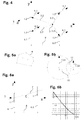
- Figure 1 shows a sketch for determining the repeller parameters: the repeller 1 comprises a wing 1.1 and an axis of rotation.
- the wing 1.1 in this example and in the projection shown here on the plane perpendicular to the axis of rotation, has the shape of a right-angled triangle.
- One of the acute angles of this triangle is at the center 1.2 of the repeller.
- the rotation thing pierces the paper plane at the center 1.2.
- the other pointed corner of the triangle is the outermost point 1.11 of the wing 1.1.
- the extreme point 1.11 describes, when rotating around the axis of rotation, a circle, the repeller circle 1.4.
- the repeller circle 1.4 has a radius 1.3 which corresponds to the distance between the outermost point 1.11 of the wing 1.1 to the center 1.2.
- a wing 1.1 has several outermost points 1.11, the most forward of these several points can be used, for example.
- the center point 1.2 can always be defined as the intersection point of the axis of rotation through the repeller circuit 1.4.
- Figure 2 is a sketch to explain the different levels and positional relationships of the wind turbine.
- the wind turbine system shown comprises three repellers 1. Their center points represent the corners of a triangle: this triangle is the arrangement surface 7.1.
- the arrangement area 7.1 lies in the arrangement level 7.
- the repellers 1 each define repeller circles 1.4, which in turn lie in repeller levels 6.1 and 6.2.
- a repeller 1 lies in a front repeller level 6.1 and two repellers 1 in a rear repeller level 6.2.
- the repeller levels 6.1 and 6.2 are parallel to each other.
- the positional relationship "front” and "rear” results from the operating direction.
- the wind should blow in the operating direction in the direction designated x.
- the arrangement surface 7.1 has an axis of symmetry 7.2.
- the direction designated x runs along the axis of symmetry 7.2.
- An axis of rotation 3.1 penetrates the arrangement surface 7.1 on the axis of symmetry 7.2.
- the z-direction runs parallel to the axis of rotation 3.1 and points in the direction opposite to the perpendicular direction.
- the coordinate system used should be right-handed and have its origin in the center 1.2 of the repeller 1 in the front repeller plane 6.1.
- the Figures 3a-e show different examples of repeller arrangements. All arrangements are shown in the view on arrangement level 7. The Figures 3a-e all show the operating arrangement.
- Figure 3a shows the arrangement "triangle in the wind”: the repeller arrangement 2 comprises exactly three repellers 1.
- the repeller centers 1.2 are arranged in the form of an isosceles triangle.
- Repellers 1 all have the same radius.
- the arrangement surface 7.1 is an isosceles triangle.
- the triangle has an axis of symmetry 7.11.
- Repeller 1 is located in two repeller levels 6.1 and 6.2. There is a repeller 1 in the front repeller level 6.1 and two repellers in the rear repeller level 6.2.
- the center of gravity 4 is 2/3 of the height of the triangle, that is, the length of the axis of symmetry 7.11, measured from the tip, that is, the center of the front repeller 1.
- the intersection point 3 of the axis of rotation also lies on the axis of symmetry 7.11, namely in front of the center of gravity 4.
- FIG. 3b shows the arrangement "triangle against the wind”:
- the repeller arrangement is very similar to the arrangement "triangle against the wind”.
- the operational orientation is rotated by 180 °: the wind 5 now strikes the base of the triangle, that is to say the front repeller level 6.1, which now has two repellers 1.
- the center of gravity is now 1/3 the height of the triangle or 1/3 the length of the axis of symmetry 7.11.
- the intersection point 3 of the axis of rotation lies on the axis of symmetry 7.11 and in front of the center of gravity 4.
- Figure 3c shows a further repeller arrangement 2.
- the arrangement surface 7.1 has the shape of a symmetrical trapezoid, the smaller of the two parallel sides facing the wind 5.
- the repellers 1 all have the same radius.
- the repellers 1 are arranged symmetrically.
- a repeller 1 lies in the middle between two further repellers 1.
- the axis of symmetry 7.11 runs parallel to the wind direction 5.
- the intersection point 3 of the axis of rotation through the arrangement surface lies in front of the center of gravity 4.
- FIG. 3d shows a further repeller arrangement 2.
- the arrangement surface 7.1 has the shape of a hexagon.
- the repeller arrangement 2 comprises a total of seven repellers 1.
- the repellers 1 are arranged on a total of three repeller levels 6.1, 6.2 and 6.3.
- the distance between the front repeller level 6.1 and the middle repeller level 6.2 is equal to the distance between the middle repeller level 6.2 and the rear repeller level 6.3.
- the arrangement surface 7.1 has an axis of symmetry 7.11 which runs parallel to the wind direction 5.
- Another axis of symmetry of the hexagon runs in the middle repeller level 6.2. However, this is not the axis of symmetry according to the invention through which the axis of rotation passes. Assuming that all repellers 1 have the same radius, the center of gravity 4 lies precisely at the center of the middle repeller 1 of the middle repeller level 6.2. The intersection point 3 of the axis of rotation lies in front of the load center of gravity 4, specifically on the axis of symmetry 7.11 between the front repeller level 6.1 and the middle repeller level 6.2.
- Figure 3e shows a repeller arrangement 2 of the type "triangle in the wind". It comprises three repellers 1, the arrangement surface 7.1 of which represents an isosceles triangle, the tip of which points into the wind 5.
- the front repeller level 6.1 is parallel to the rear repeller level 6.2.
- a repeller 1 is located on the front repeller level 6.1, and two repellers 1 are located on the rear repeller level 6.2.
- the two repellers 1 of the rear repeller level 6.2 have the same radius r2.
- the repeller 1 of the front repeller level 6.1 has the radius r1.
- the radius of the repeller 1 of the front repeller level 6.1 is twice as large as the radius of one of the repellers 1 of the rear repeller level 6.2.
- intersection point 3 of the axis of rotation lies in front of the center of gravity 4.
- Figure 4 shows a sketch for the calculation of the torque.
- This sketch shows the xy plane as in Figure 2 was introduced and a total of four centers 1.2 arranged symmetrically about the x-axis.
- the y-axis lies in the front repeller level 6.1 and the x-axis in the arrangement plane.
- the front repeller level 6.1 and the rear repeller level 6.2 are at a distance 8 from one another.
- intersection point 3 lies on the x axis by choice of the coordinate system and therefore has the coordinates (p, 0.0).
- Any center with index i lies in the x-y plane and therefore has the coordinates (xi, yi, 0).
- M z . i F i x i - p sin a - y i cos a
- Mz In order to generate a rotation which leads to the symmetry axis of the arrangement including the angle a with the x axis, Mz should be positive.
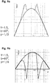
- Figure 5a is to show the concept of the convex hull 9: A lot of points are shown.
- the convex envelope 9 in the sense of this document is the line shown.
- the area enclosed by the line is the area in which all points lie and all connecting lines of these points. At the same time, the area is not larger than necessary to meet these conditions.
- Figure 5b illustrates the overlapping of two circles: Both circles have a center 1.2 and a radius 1.3.
- the triangle which is spanned by the two centers and the intersection of the circles, has the side lengths D, r1 and r2.
- triangles which are spanned by a center point and the two intersection points of the circles, must now be subtracted from this area. They are isosceles triangles with a half opening angle of ⁇ 1 or ⁇ 2 and a leg length of r1 or r2.
- Figure 6a shows a sketch to explain the possible deviation of the arrangement level from the vertical to the repeller levels.
- the arrangement level 7 should be essentially perpendicular to the repeller level. If it is not exactly vertical, the coordinate system should preferably be attached to the repeller plane and not to the arrangement plane: In case of doubt, the x-axis is therefore perpendicular to the repeller plane, even if arrangement plane 7 deviates slightly from it.
- the arrangement level should be aligned in such a way that there is still a shading effect. That in the case of wind parallel to the x-y plane, a front repeller or a front wind obstacle should be able to shade a rear repeller or a rear wind obstacle.
- Figure 6a shows such an arrangement: The projection of the repeller arrangement on the xz plane is shown. One looks at the edges of the arrangement level 7 and the repeller levels 6.1 and 6.2, so that they appear here as mere lines. The arrangement level 7 deviates from the normal to the repeller levels 6.1 and 6.2 by the angle c. The distance 8 of the repeller levels 6.1 and 6.2 from one another is also shown.
- D / (2r) can be between 0 and 1.
- this expression is also used when estimating the shading effect. It is about S ⁇ r 2 the normalized shading in the case of two circles of equal size.
- Figure 7a explains the shadowing effect using the example of the "triangle in the wind" repeller arrangement.
- the arrangement surface is an isosceles triangle with an axis of symmetry 7.11.
- the wind direction 5 in the operating orientation is parallel to the axis of symmetry 7.11.
- the isosceles triangle of the arrangement surface has a half opening angle b and a height h, which is equal to the distance between the repeller planes 8.
- the repellers have a radius r. We assume here that the radii of all repellers 1 are the same.
- the angle between wind direction and axis of symmetry 7.11 should now increase.
- the angle between wind direction and axis of symmetry 7.11 is denoted by a.
- repeller C gets into the slipstream of repeller A.
- repeller C emerges from the slipstream again.
- repeller A then falls into the slipstream of repeller B. This happens between the angles a minA and a maxA .
- Figure 7b shows the same situation for the "triangle against the wind” arrangement: the sketch clearly shows that shading occurs at the same angles as in the "triangle against the wind” arrangement.
- Figure 8a shows the top view of the arrangement surface 7.1 of a repeller arrangement with 3 repellers 1 in the constellation "triangle in the wind": the wind direction 5 is in the operational orientation.
- the point of intersection of the axis of rotation 3.1 is equal to the center of gravity 4.
- the arrangement surface 7.1 has the shape of an isosceles triangle with a half opening angle b.
- the area 16 which is used by the repeller arrangement is a circle with the radius 16.1.
- Figure 8b shows the same view of a repeller arrangement of the constellation "triangle against the wind".
- the point of intersection of the axis of rotation 3.1 now lies clearly in front of the center of gravity 4, which is 1/3 the height of the triangle of the arrangement surface 7.1.
- the surface 16 that is used by the repeller arrangement is again a circle with the radius 16.1.
- the radius 16.1 is that in Figure 8a shown constellation larger than in the in Figure 8b shown constellation.
- Figure 9 shows the torque depending on the wind direction a.
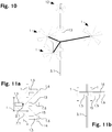
- Figure 10 shows a first wind turbine system according to the invention: Three repellers 1, each with six blades 1.1, are coupled to a repeller arrangement 2 on a common axis of rotation 3.1.
- the wind turbine system comprises a further repeller 12, which is not part of the repeller arrangement 2.
- FIG 11 shows a second embodiment of a wind turbine system according to the invention. This includes solar panels 14.
- Figure 11a shows the layout from below.
- Figure 11b shows the system from the side.
- the wind turbine plant comprises 3 repellers 1. These are each fastened with their bearings 1.5 to a support structure 15.
- the support structure has the shape of a "v”.
- the axles 1.6 driven by the repellers 1 protrude from the bearings 1.5 and are coupled to one another by belts.
- a generator unit 13 is located on the central axis 1.6.
- the center points of the repellers form an arrangement surface 7.1. This has the shape of an isosceles triangle.
- Solar panels 14 are located above the support structure 15, the bearings 1.5 and the axes 1.6.
- the solar panels 14 cover an approximately T-shaped surface.
- the axis of rotation 3.1 pierces the support structure 15 and the solar panels 14 in the area of the tip of the Vs.
- the arrangement surface 7.1 pierces the axis of rotation 3.1 at a distance of 2/3 of the height of the triangle, which represents the arrangement surface 7.1.
- repellers of the exemplary embodiments can also be replaced by suitable wind obstacles.
- geometries can be varied: Many examples relate to the triangular arrangement, but can also be realized with differently shaped arrangement surfaces.
- a wind turbine installation according to the invention can also be equipped with further repellers that do not belong to the repeller arrangement.
Landscapes
- Engineering & Computer Science (AREA)
- Life Sciences & Earth Sciences (AREA)
- Sustainable Development (AREA)
- Sustainable Energy (AREA)
- Chemical & Material Sciences (AREA)
- Combustion & Propulsion (AREA)
- Mechanical Engineering (AREA)
- General Engineering & Computer Science (AREA)
- Wind Motors (AREA)
Priority Applications (3)
| Application Number | Priority Date | Filing Date | Title |
|---|---|---|---|
| EP18180452.7A EP3587796A1 (fr) | 2018-06-28 | 2018-06-28 | Éolienne à alignement automatique |
| EP19732695.2A EP3814626B1 (fr) | 2018-06-28 | 2019-06-27 | Éolienne à alignement automatique |
| PCT/EP2019/067212 WO2020002529A1 (fr) | 2018-06-28 | 2019-06-27 | Éolienne à auto-alignement |
Applications Claiming Priority (1)
| Application Number | Priority Date | Filing Date | Title |
|---|---|---|---|
| EP18180452.7A EP3587796A1 (fr) | 2018-06-28 | 2018-06-28 | Éolienne à alignement automatique |
Publications (1)
| Publication Number | Publication Date |
|---|---|
| EP3587796A1 true EP3587796A1 (fr) | 2020-01-01 |
Family
ID=62816398
Family Applications (2)
| Application Number | Title | Priority Date | Filing Date |
|---|---|---|---|
| EP18180452.7A Withdrawn EP3587796A1 (fr) | 2018-06-28 | 2018-06-28 | Éolienne à alignement automatique |
| EP19732695.2A Active EP3814626B1 (fr) | 2018-06-28 | 2019-06-27 | Éolienne à alignement automatique |
Family Applications After (1)
| Application Number | Title | Priority Date | Filing Date |
|---|---|---|---|
| EP19732695.2A Active EP3814626B1 (fr) | 2018-06-28 | 2019-06-27 | Éolienne à alignement automatique |
Country Status (2)
| Country | Link |
|---|---|
| EP (2) | EP3587796A1 (fr) |
| WO (1) | WO2020002529A1 (fr) |
Citations (7)
| Publication number | Priority date | Publication date | Assignee | Title |
|---|---|---|---|---|
| FR893828A (fr) * | 1943-05-12 | 1944-11-02 | Groupe aérogénérateur de courant à entraînement différentiel par hélices de sens contraires à pas variant automatiquement | |
| DE19846796A1 (de) | 1998-10-10 | 2000-04-13 | Dieter Kolbert | Schwimmendes Windenergieanlagen-System |
| WO2002073032A1 (fr) | 2001-03-08 | 2002-09-19 | Ishikawajima-Harima Jukogyo Kabushiki Kaisha | Installation flottante en mer de production d'energie eolienne |
| US6749399B2 (en) | 2002-03-07 | 2004-06-15 | Ocean Wind Energy Systems | Vertical array wind turbine |
| WO2010098813A1 (fr) | 2009-02-28 | 2010-09-02 | Ener2 Llc | Dispositif à énergie éolienne |
| DE102009040648A1 (de) | 2009-09-09 | 2011-03-10 | Wilhelm Ebrecht | Schwimmfähige Offshore-Windkraftanlage |
| US20150247486A1 (en) * | 2012-09-10 | 2015-09-03 | Wepfer Technics Ag | Wind turbine |
Family Cites Families (2)
| Publication number | Priority date | Publication date | Assignee | Title |
|---|---|---|---|---|
| WO2011137903A2 (fr) * | 2010-05-05 | 2011-11-10 | Stephan Moellgaard Henriksen | Parc d'éoliennes semi-submergé |
| CN105240221B (zh) * | 2014-07-08 | 2019-05-07 | 珠海卡洛斯工程咨询有限公司 | 半潜筏式随风转向水上风力发电设备 |
-
2018
- 2018-06-28 EP EP18180452.7A patent/EP3587796A1/fr not_active Withdrawn
-
2019
- 2019-06-27 EP EP19732695.2A patent/EP3814626B1/fr active Active
- 2019-06-27 WO PCT/EP2019/067212 patent/WO2020002529A1/fr active Application Filing
Patent Citations (7)
| Publication number | Priority date | Publication date | Assignee | Title |
|---|---|---|---|---|
| FR893828A (fr) * | 1943-05-12 | 1944-11-02 | Groupe aérogénérateur de courant à entraînement différentiel par hélices de sens contraires à pas variant automatiquement | |
| DE19846796A1 (de) | 1998-10-10 | 2000-04-13 | Dieter Kolbert | Schwimmendes Windenergieanlagen-System |
| WO2002073032A1 (fr) | 2001-03-08 | 2002-09-19 | Ishikawajima-Harima Jukogyo Kabushiki Kaisha | Installation flottante en mer de production d'energie eolienne |
| US6749399B2 (en) | 2002-03-07 | 2004-06-15 | Ocean Wind Energy Systems | Vertical array wind turbine |
| WO2010098813A1 (fr) | 2009-02-28 | 2010-09-02 | Ener2 Llc | Dispositif à énergie éolienne |
| DE102009040648A1 (de) | 2009-09-09 | 2011-03-10 | Wilhelm Ebrecht | Schwimmfähige Offshore-Windkraftanlage |
| US20150247486A1 (en) * | 2012-09-10 | 2015-09-03 | Wepfer Technics Ag | Wind turbine |
Also Published As
| Publication number | Publication date |
|---|---|
| EP3814626A1 (fr) | 2021-05-05 |
| EP3814626C0 (fr) | 2023-11-29 |
| EP3814626B1 (fr) | 2023-11-29 |
| WO2020002529A1 (fr) | 2020-01-02 |
Similar Documents
| Publication | Publication Date | Title |
|---|---|---|
| DE102006021182B4 (de) | Fluggerät mit vier Hubrotoren und drei Drehachsen als universelle Flugplattform | |
| DE2604005A1 (de) | Einrichtung zur beeinflussung der position und lage eines satelliten | |
| CH700332B1 (de) | Windkraftanlage. | |
| DE2320514A1 (de) | Spezielle unterwasserfahrzeuge, die ein neues integriertes auftriebs-, vortriebsund steuerungssystem verwenden | |
| DE102011052668A1 (de) | Nabe für eine Windkraftanlage und Verfahren zur Montage einer Windkraftanlage | |
| DE69400921T2 (de) | Satellit mit aerodynamischer steuereinrichtung | |
| EP2075461B1 (fr) | Procédé et système destinés à transformer l'énergie cinétique comprise dans des courants horizontaux en énergie mécanique utilisable | |
| DE2814813A1 (de) | Windkraftmaschine | |
| DE69510322T2 (de) | Erzeugung von elektrischer energie durch wind angetriebene vorrichtung | |
| EP3814626B1 (fr) | Éolienne à alignement automatique | |
| DE2318788C2 (de) | Hochgeschwindigkeitswasserfahrzeug | |
| EP2307709A2 (fr) | Turbomachine avec roues à aubes | |
| DE202019000936U1 (de) | Universalflugerät mit Elektroantrieb | |
| DE102017126691A1 (de) | Windkraftanlage | |
| EP4189235A1 (fr) | Hélice universelle, procédé de fonctionnement et utilisations privilégiées | |
| DE202010016041U1 (de) | Windkraftanlage und Windpark | |
| DE102009008805A1 (de) | Windkraftanlage | |
| DE3810339A1 (de) | Windkraftanlage | |
| DE3713024A1 (de) | Stroemungsmaschine zur energiegewinnung | |
| DE102012005231A1 (de) | Windkraftanlage mit vertikaler Achse | |
| DE102016110204A1 (de) | Windrad und Windkraftanlage | |
| EP3508421A1 (fr) | Mécanisme d'entraînement d'hélicoptère et procédé de fonctionnement d'un mécanisme d'entraînement d'hélicoptère | |
| DE102010026706A1 (de) | Befestigungsvorrichtung für Flettner-Rotoren | |
| DE19835958B4 (de) | Durch Windkraft antreibbarer Rotor | |
| EP4091939A1 (fr) | Aéronef |
Legal Events
| Date | Code | Title | Description |
|---|---|---|---|
| PUAI | Public reference made under article 153(3) epc to a published international application that has entered the european phase |
Free format text: ORIGINAL CODE: 0009012 |
|
| STAA | Information on the status of an ep patent application or granted ep patent |
Free format text: STATUS: THE APPLICATION HAS BEEN PUBLISHED |
|
| AK | Designated contracting states |
Kind code of ref document: A1 Designated state(s): AL AT BE BG CH CY CZ DE DK EE ES FI FR GB GR HR HU IE IS IT LI LT LU LV MC MK MT NL NO PL PT RO RS SE SI SK SM TR |
|
| AX | Request for extension of the european patent |
Extension state: BA ME |
|
| STAA | Information on the status of an ep patent application or granted ep patent |
Free format text: STATUS: THE APPLICATION IS DEEMED TO BE WITHDRAWN |
|
| 18D | Application deemed to be withdrawn |
Effective date: 20200702 |