EP3587796A1 - Self-aligning wind turbine installation - Google Patents
Self-aligning wind turbine installation Download PDFInfo
- Publication number
- EP3587796A1 EP3587796A1 EP18180452.7A EP18180452A EP3587796A1 EP 3587796 A1 EP3587796 A1 EP 3587796A1 EP 18180452 A EP18180452 A EP 18180452A EP 3587796 A1 EP3587796 A1 EP 3587796A1
- Authority
- EP
- European Patent Office
- Prior art keywords
- repeller
- wind
- arrangement
- repellers
- axis
- Prior art date
- Legal status (The legal status is an assumption and is not a legal conclusion. Google has not performed a legal analysis and makes no representation as to the accuracy of the status listed.)
- Withdrawn
Links
- 238000009434 installation Methods 0.000 title description 2
- 230000005484 gravity Effects 0.000 claims abstract description 37
- 230000000694 effects Effects 0.000 claims description 23
- 238000000034 method Methods 0.000 claims description 4
- 230000008901 benefit Effects 0.000 description 12
- 230000008878 coupling Effects 0.000 description 9
- 238000010168 coupling process Methods 0.000 description 9
- 238000005859 coupling reaction Methods 0.000 description 9
- 230000007423 decrease Effects 0.000 description 7
- 101150067055 minC gene Proteins 0.000 description 7
- 230000001419 dependent effect Effects 0.000 description 4
- 238000007667 floating Methods 0.000 description 4
- 238000012423 maintenance Methods 0.000 description 4
- 241001295925 Gegenes Species 0.000 description 3
- 238000013461 design Methods 0.000 description 3
- 238000005259 measurement Methods 0.000 description 3
- 230000035515 penetration Effects 0.000 description 3
- 230000002349 favourable effect Effects 0.000 description 2
- 238000010248 power generation Methods 0.000 description 2
- 230000008569 process Effects 0.000 description 2
- 230000002787 reinforcement Effects 0.000 description 2
- 229910000679 solder Inorganic materials 0.000 description 2
- 101100129500 Caenorhabditis elegans max-2 gene Proteins 0.000 description 1
- VVQNEPGJFQJSBK-UHFFFAOYSA-N Methyl methacrylate Chemical compound COC(=O)C(C)=C VVQNEPGJFQJSBK-UHFFFAOYSA-N 0.000 description 1
- 229920005372 Plexiglas® Polymers 0.000 description 1
- 230000001133 acceleration Effects 0.000 description 1
- 230000001154 acute effect Effects 0.000 description 1
- 238000004873 anchoring Methods 0.000 description 1
- 230000005540 biological transmission Effects 0.000 description 1
- 230000015572 biosynthetic process Effects 0.000 description 1
- 230000008859 change Effects 0.000 description 1
- 238000006243 chemical reaction Methods 0.000 description 1
- 238000012937 correction Methods 0.000 description 1
- 230000003247 decreasing effect Effects 0.000 description 1
- 230000005611 electricity Effects 0.000 description 1
- 230000007613 environmental effect Effects 0.000 description 1
- 230000003993 interaction Effects 0.000 description 1
- 238000004519 manufacturing process Methods 0.000 description 1
- 230000000873 masking effect Effects 0.000 description 1
- 239000000463 material Substances 0.000 description 1
- 239000000047 product Substances 0.000 description 1
- 230000009467 reduction Effects 0.000 description 1
- 230000004044 response Effects 0.000 description 1
- 239000013589 supplement Substances 0.000 description 1
- XLYOFNOQVPJJNP-UHFFFAOYSA-N water Substances O XLYOFNOQVPJJNP-UHFFFAOYSA-N 0.000 description 1
Images


Classifications
-
- F—MECHANICAL ENGINEERING; LIGHTING; HEATING; WEAPONS; BLASTING
- F03—MACHINES OR ENGINES FOR LIQUIDS; WIND, SPRING, OR WEIGHT MOTORS; PRODUCING MECHANICAL POWER OR A REACTIVE PROPULSIVE THRUST, NOT OTHERWISE PROVIDED FOR
- F03D—WIND MOTORS
- F03D1/00—Wind motors with rotation axis substantially parallel to the air flow entering the rotor
- F03D1/02—Wind motors with rotation axis substantially parallel to the air flow entering the rotor having a plurality of rotors
-
- F—MECHANICAL ENGINEERING; LIGHTING; HEATING; WEAPONS; BLASTING
- F03—MACHINES OR ENGINES FOR LIQUIDS; WIND, SPRING, OR WEIGHT MOTORS; PRODUCING MECHANICAL POWER OR A REACTIVE PROPULSIVE THRUST, NOT OTHERWISE PROVIDED FOR
- F03D—WIND MOTORS
- F03D7/00—Controlling wind motors
- F03D7/02—Controlling wind motors the wind motors having rotation axis substantially parallel to the air flow entering the rotor
- F03D7/0204—Controlling wind motors the wind motors having rotation axis substantially parallel to the air flow entering the rotor for orientation in relation to wind direction
-
- F—MECHANICAL ENGINEERING; LIGHTING; HEATING; WEAPONS; BLASTING
- F05—INDEXING SCHEMES RELATING TO ENGINES OR PUMPS IN VARIOUS SUBCLASSES OF CLASSES F01-F04
- F05B—INDEXING SCHEME RELATING TO WIND, SPRING, WEIGHT, INERTIA OR LIKE MOTORS, TO MACHINES OR ENGINES FOR LIQUIDS COVERED BY SUBCLASSES F03B, F03D AND F03G
- F05B2220/00—Application
- F05B2220/70—Application in combination with
- F05B2220/708—Photoelectric means, i.e. photovoltaic or solar cells
-
- F—MECHANICAL ENGINEERING; LIGHTING; HEATING; WEAPONS; BLASTING
- F05—INDEXING SCHEMES RELATING TO ENGINES OR PUMPS IN VARIOUS SUBCLASSES OF CLASSES F01-F04
- F05B—INDEXING SCHEME RELATING TO WIND, SPRING, WEIGHT, INERTIA OR LIKE MOTORS, TO MACHINES OR ENGINES FOR LIQUIDS COVERED BY SUBCLASSES F03B, F03D AND F03G
- F05B2250/00—Geometry
- F05B2250/30—Arrangement of components
-
- Y—GENERAL TAGGING OF NEW TECHNOLOGICAL DEVELOPMENTS; GENERAL TAGGING OF CROSS-SECTIONAL TECHNOLOGIES SPANNING OVER SEVERAL SECTIONS OF THE IPC; TECHNICAL SUBJECTS COVERED BY FORMER USPC CROSS-REFERENCE ART COLLECTIONS [XRACs] AND DIGESTS
- Y02—TECHNOLOGIES OR APPLICATIONS FOR MITIGATION OR ADAPTATION AGAINST CLIMATE CHANGE
- Y02E—REDUCTION OF GREENHOUSE GAS [GHG] EMISSIONS, RELATED TO ENERGY GENERATION, TRANSMISSION OR DISTRIBUTION
- Y02E10/00—Energy generation through renewable energy sources
- Y02E10/70—Wind energy
- Y02E10/72—Wind turbines with rotation axis in wind direction
Definitions
- the invention relates to a self-aligning wind turbine system.
- the WO 02/073032 and the DE 19846796 disclose combinations of linked repellers that float on rafts or similar devices and are attached to a common anchor point or buoy that is outside the area delimited by the repellers. These wind turbine systems align wind and surface flow in such a way that the repellers are always blown from the front.
- the DE 19846796 also proposes a support or a correction of the alignment by rudders and / or drives that react to wind direction measurements.
- the DE 10 2009 040 648 A1 discloses a floating offshore wind turbine with a floating body, at least one mast arranged thereon, on which at least one rotor is rotatably mounted.
- the mast should have a teardrop-shaped cross section, which means that the floating body turns easily and quickly into the wind so that the rotors are always optimally aligned with the wind direction without the need for complex, additional adjustment.
- the DE 10 2009 040 648 A1 explains that the system turns into the wind independently, since the fulcrum is located on the foundation outside the float.
- a wind turbine system intended for use on land reveals, among other things, the US 6749399 :
- the repeller centers are arranged on a common tower on a circle around a common axis of rotation. To achieve the wind orientation, the tower is rotated as a whole.
- Another example is WO 2010/098813 showing plants with two repellers. Both documents propose to use a motor to align the system in the wind.
- the object of the invention is to provide a wind turbine system belonging to the technical field mentioned at the outset, which is particularly low-maintenance and can be used on land, in particular for private power generation and for small producers.
- the self-aligning wind turbine system comprises a repeller arrangement with at least three wind obstacles rigidly arranged relative to one another, of which at least two, in particular all wind obstacles, are repellers.
- Each of the repellers of the repeller arrangement has at least one wing.
- the wing can rotate about an axis of rotation of the respective repeller.
- the repeller is in its operating orientation when it is blown from the front.
- a foremost and most distant point of the said wing sweeps over a circle with one revolution around the axis of rotation. This circle defines the radius of the repeller.
- the center of this circle lies on the axis of rotation and defines the center of the repeller.
- a repeller is a wind obstacle.
- a wind obstacle which belongs to the repeller arrangement and which is not a repeller is shaped and arranged in such a way that in a configuration in which the wind flows against the repeller of the repeller arrangement from the front, its surface facing the wind is rotationally symmetrical.
- the axis of symmetry runs in the wind direction and defines the axis of rotation of the wind obstacle.
- the axis of rotation of the wind obstacle pierces the wind obstacle at its center.
- the center of the wind obstacle is defined as the foremost, common point of the wind obstacle and the axis of rotation of the wind obstacle.
- the centers of the at least three wind obstacles of the repeller arrangement are in at least two, parallel to one another and spaced apart Repeller levels arranged.
- the repeller planes are perpendicular to the axes of rotation of the wind obstacles, in particular to the axes of rotation of the repellers. All repellers in the repeller arrangement are aligned identically.
- the centers of the at least three wind obstacles lie in a common arrangement level.
- the arrangement level is essentially perpendicular to the repeller levels.
- the convex hull of all centers of all wind obstacles of the repeller arrangement defines an arrangement surface.
- the arrangement surface is mirror-symmetrical and therefore has an axis of symmetry.
- the axis of symmetry runs essentially parallel to the axes of rotation.
- the wind turbine system also includes an axis of rotation.
- the repeller arrangement can be rotated about this axis of rotation, so that self-alignment is possible.
- the point of intersection of the axis of rotation through the arrangement surface lies on the axis of symmetry and in front of the center of gravity of the load.
- the center of gravity is the center of gravity weighted with the flow resistance of the wind obstacles of the repeller arrangement.
- “rigidly arranged to one another” should preferably mean here and below that the centers of the repellers and possibly the wind obstacles and the axes of rotation of the repellers and possibly the wind obstacles cannot shift or twist against one another. However, it should still be possible to have a certain elasticity of the arrangement, which allows unusually large forces to be absorbed by a brief deformation of the arrangement. In addition, the rigid arrangement does not rule out the fact that the repeller blades can rotate and that the arrangement as a whole can be rotated and possibly also shifted.
- Wind obstacles other than repellers that are part of the arrangement should also be able to make certain movements and deformations, although they are rigidly arranged if only their center point and their axis of rotation remain in a fixed position and in a fixed orientation relative to the other parts of the arrangement.
- the orientation of a repeller is the position of its axis of rotation in relation to the wind direction.
- the operational orientation of a repeller is preferably the orientation in the wind at which the repeller is most efficient, i.e. draws most of the energy from the wind.
- convex hull this document means the edge of the convex hull in the mathematical sense.
- the convex hull i.e. the edge of the convex hull in the mathematical sense, is a self-contained curve without concave sections. If you imagine the center points as nails, which are stuck in a board, you get the convex envelope, i.e. the edge of the convex envelope in the mathematical sense, by stretching a rubber band around the nails.
- the arrangement surface includes all and only all points of the convex hull in the mathematical sense.
- the axis of symmetry of a surface should be understood according to the following common definition:
- the surface is axisymmetric if there is a straight line, so that for each point P of the surface there is a further point P 'of the surface (possibly identical with P), so that the connecting path [PP'] is halved at right angles by this straight line.
- This line is then called the axis of symmetry.
- the axis of rotation is a geometric axis here and not necessarily a real, continuous axis. It would be conceivable, for example, that the repeller arrangement is mounted on a cylinder-like tower with a circular or polygonal cross section, which can rotate about the axis of rotation and the repeller arrangement mounted thereon in relation to the ground.
- the point of intersection of the axis of rotation through the arrangement surface is therefore the point on the arrangement surface which does not change its position in relation to the ground and the environment during the process of self-alignment in the wind.
- the center of gravity of the center of all wind obstacles in the repeller arrangement is calculated as follows: A two-dimensional Cartesian coordinate system is selected so that the arrangement area can be completely described.
- the repeller arrangement should include N wind obstacles, each with a center point. These N center points each lie at (x i , y i ), the center points being numbered consecutively.
- the flow resistance of each wind obstacle in its operational orientation is given, for example, by the product of its c w value and its reference area A.
- the arrangement plane is essentially perpendicular to the repeller planes and the axis of symmetry runs essentially parallel to the axes of rotation.
- R1max is the largest radius of a wind obstacle in a front repeller plane and R2max is the largest radius of a wind obstacle in a rear repeller plane and D is the distance between the two repeller planes considered.
- the angle between the vertical on the repeller planes and the arrangement plane, or between the axes of rotation and the axis of symmetry, is preferably between 0 ° and arctan (0.4 * (R1max + R2max) / D), particularly preferably only between 0 ° and arctan (0.16 * (+ r1max R2max) / D).
- the resulting wind turbine system therefore has a long service life and does not require any special drives or controls to align itself in the wind. It is therefore particularly low-maintenance.
- a wind pressure force of F acts on each wind obstacle, where a is the clockwise deviation of the wind direction from that which is ideal for operation Is wind direction.
- the coordinate system is chosen so that the axis of symmetry runs on the x-axis and the arrangement surface lies in the xy plane. The point of intersection of the axis of rotation also lies on the axis of symmetry and therefore has the coordinates (p, 0).
- the present annex therefore goes a third way and changes the basic assumption of the calculation described above:
- the force acting on the wind obstacles changes depending on the wind direction and not only with the sine term that is known from the shade-free model.
- the wind obstacles must therefore be arranged symmetrically and / or suitably according to their flow resistance.
- G N x G > p , G / N G / N is the average weighting factor.
- the situation with shading can be represented by a weighting factor g i (a) dependent on a.
- the torque M z results for all a outside the interval 10 ° ⁇ a ⁇ 80 ° FN sin a x G - p ,
- the contribution of x 2 must be taken out of the sum of the sin term and the no longer compensated contribution of y 3 must be added in the cosine term.
- M z FN sin a x G - p + 1 N cot a y 2 - x 2 - p
- cot (a) must be y 2 > x 2 , or y 2 > tan (a) x 2 . If the effect is to be positive for the entire angular interval from 10 ° to 80 °, the shadowed wind obstacle should have a center that meets the condition y 2 > tan (80 °) (x 2 -p). In many cases, however, the increase in torque will primarily be desired at smaller angles, so that positioning the wind obstacle in other locations is also of interest.
- all wind obstacles in the repeller arrangement are repellers.
- This embodiment draws a particularly large amount of energy from the wind hitting the repeller arrangement and therefore has a good efficiency.
- the wind obstacles can be formed, for example, by solar cells or by plexiglass panes.
- This embodiment allows self-alignment to be used when the resources for more than two repellers are lacking.
- the system can also be kept operational in this way if a repeller fails.
- the use of solar cells as wind obstacles can provide a power supply even at times when there is no wind.
- the distance between the centers of any two repellers within a repeller plane is greater than the sum of the radii of the repellers under consideration. In this embodiment, this is the case for all repellers of the repeller arrangement.
- Repellers can also be arranged in such a way that the wings "interlock": A point in the middle between two repeaters of the same size arranged in this way, wings of both repellers pass alternately, if they have the same number of wings. Such an arrangement is particularly compact.
- At least two repellers of the repeller arrangement are speed-coupled to one another.
- Speed-coupled repellers should be connected to one another in such a way that their speeds are in a fixed relationship to one another, preferably they should have the same speed.
- At least two of the repellers of the repeller arrangement drive a common generator.
- At least two of the repellers of the repeller arrangement are speed-coupled and drive a common generator.
- this arrangement has the advantage that the gears between the repeller axes and the generator axis can be designed in a particularly simple manner.
- At least one repeller of the front repeller level is speed-coupled to at least one repeller of one of the rear repeller levels.
- the speed-coupled repellers jointly drive a generator. All are preferred Repellers of the repeller arrangement are speed-coupled to one another and jointly drive a generator.
- the speed coupling between repellers of second repeller levels has the advantage that the repeller of the rear repeller level can be shaded from the wind by the repeller of the front repeller level coupled to it.
- the front repeller is braked by the coupling against its free rotation speed, its resistance and thus the efficiency of its wind shading ability increase.
- the wind shading effect can therefore be more pronounced.
- all centers of the wind obstacles, in particular the repellers, of the repeller arrangement lie on the convex hull of the centers of all wind obstacles of the repeller arrangement.
- This embodiment has the advantage that there is little interference between the repellers.
- the rigid connection between the repellers can be easily achieved and there is space in the free arrangement area for other components, such as the generator or solar panels.
- wind obstacles of the repeller arrangement with their center points also lie within the arrangement surface. This allows a compact design.
- all the repellers of the wind turbine system are part of the repeller arrangement.
- the wind turbine system comprises repellers that do not belong to the repeller arrangement.
- Repellers not belonging to the repeller arrangement can, for example, be above or below the arrangement level or their arrangement is not symmetrical. Such repellers can be used for measurements or for power generation that is independent of the repeller arrangement. Such repellers can be aligned depending on the repeller arrangement, or they can be aligned using your own wind vanes or motors. There can also be repellers with a fixed orientation in a frequently occurring wind direction.
- the angle between a perpendicular to the repeller level and each of the connecting lines between the center of any repeller of the first repeller level and the center of any repeller of a second repeller level, which is not equal to that of the first repeller level is greater than arctan ((r1 + r2) / h). In particular, this angle is greater than 3 ° + arctan ((r1 + r2) / h).
- r1 and r2 are the repeller radii of the repellers under consideration.
- h is the distance between the first and second repeller levels.
- the angle between a perpendicular to the repeller plane and at least one individual connecting line between second centers is smaller than arctan ((r1 + r2) / h).
- all repellers of the repeller arrangement in particular all repellers of the wind turbine system, have the same radius.
- repellers of different radii there are repellers of different radii in a repeller arrangement.
- this can allow the system to work at least partially optimally for different wind strengths, and on the other hand, the self-alignment function can be optimized in such a way that a large repeller can completely cover a smaller one over a wider angular range than would be possible with two repellers of the same size.
- g i (a) can be influenced in this way by the choice of the repeller radii.
- the repeller arrangement comprises exactly three repellers.
- the wind turbine system preferably comprises exactly three repellers.
- this embodiment is the embodiment according to the invention with the fewest repellers.
- this has the advantage that there is only slight interference between the repellers.
- the system is easy to implement mechanically and can be adapted well to the desired properties.
- a system with three repellers and two wind obstacles can be used if it is necessary for the desired self-alignment function because, for example, reinforcement over a wider or different angular range is desired than can be achieved using the repellers alone.
- a wind turbine system with exactly three repellers preferably comprises a repeller arrangement with exactly three repellers and thus has the advantages described above. Eliminating further repellers has the advantage that the process is easier and is cheaper and the additional repellers do not hinder or disturb the repellers of the repeller arrangement mechanically or fluidically.
- exactly one repeller of the repeller arrangement with radius r1 with its center in the foremost repeller plane and exactly two repellers of the repeller arrangement with radius r2 with their centers are arranged in a second repeller plane.
- the first and the second repeller plane have the distance h from each other, so that the convex hull of the center points represents an isosceles triangle.
- intersection of two circles can be calculated as follows, where d is the distance between the two center points.
- the arccos should be in radians.
- S a r 1 2 arccos r 1 2 + r 2 2 + d a 2 2 d a r 1 + r 2 2 arccos r 2 2 - r 1 2 + d a 2 2 d a r 2 - r 1 2 - r 2 2 + d a 2 2 d a r 1 2 - r 1 2 - r 2 2 + d a 2 2 d a 2 - r 2 2 - r 1 2 + d a 2 2 d a 2 - r 2 2 - r 1 2 + d a 2 2 d a 2 - r 2 2 - r 1 2 + d a 2 2 d a 2 - r 2 2 - r 1 2 + d a 2 2 d a 2 -
- the first repeller center can be at (0,0), the second and third at (2, -2) and (2,2).
- the repellers in the rear repeller level should have the diameter r2, and the repellers in the front repeller level should have the diameter r1.
- the repeller 3 becomes arctan in the angular range tan b y - 1 y ⁇ a ⁇ arctan tan b y + 1 y covered by repeller 1.
- the area of one of the repellers lies entirely within the other. The crossover area is therefore equal to the area of the smaller repeller circle.
- Repeller 1 is in the angular range 180 ° - arctan tan b y + 1 y ⁇ a ⁇ 180 ° 180 ° - arctan tan b y - 1 y 180 ° covered by repeller 2.
- the area of one of the repellers lies entirely within the other. The crossover area is therefore equal to the area of the smaller repeller circle.
- S 1 a ⁇ r 2 2 therefore resembles S 3 a ⁇ r 2 2 with these other limits.
- M z F 3 sin a x G - p + S 3 a ⁇ r 2 2 2 r 1 r 2 2 + 1 y r 1 + r 2 cot a - y r 1 + r 2 cot b + p + S 1 a ⁇ r 2 2 2 r 1 r 2 2 + 1 cot a 0 - 0 + p
- S 3 (a) is not equal to 0 only for 0 ° ⁇ a ⁇ 90 °.
- the tangent is positive in this area.
- S 1 (a) is greater than or equal to 0. greater than zero S 1 (a) at angles between 90 ° and 180 °.
- the desired reinforcement effect of the self-alignment function therefore occurs between arctan tan b y - 1 y ⁇ a ⁇ b + Slightly dependent on p H one and then again at 180 ° - arctan tan b y + 1 y ⁇ a ⁇ 180 ° - arctan tan b y - 1 y ,
- the distance between two repeller planes, the radius of the largest repeller in the rear plane, which can be shaded by a repeller in the front plane and the penetration point of the axis of rotation is selected such that the ratio of the torque with shadowing effect to the torque without shadowing effect with a flow of wind with a wind angle greater than or equal to 1.05.
- the wind angle is equal to the angle between the connecting line from the shadowing to the shaded repeller and the axis of symmetry.
- the amplitude generated by the shading should be significant compared to the unshaded amplitude.
- a unshaded sin a x G H - p H
- a shaded sin a G i N S i a ⁇ r 2 y i H cot a - x i H - p H + sin a x G H - p H
- Effective shading is preferably present precisely when A shaded A unshaded ⁇ 1:05 is.
- this condition gives the greatest preferred ratio of h / r: H r ⁇ - ln 00:05 2 H p - 3 cosb 0.3
- the extent of the triangle should therefore preferably be the following: 2 1 sin b 2 - 1 ⁇ H r ⁇ - ln 00:05 2 H p - 3 cos b 0.3 the shading effect is most evident at the lower limit of h / r.
- exactly two repellers of the repeller arrangement with radius r2 are arranged with their centers in the foremost repeller plane and exactly one repeller of the repeller arrangement with radius r1 is arranged with its center in a second repeller plane.
- the convex hull of the center points represents an isosceles triangle.
- This embodiment differs from the previous one in the operating direction.
- Repeller 2 becomes arctan in the angular range tan b y - 1 y ⁇ a ⁇ arctan tan b y + 1 y covered by repeller 1.
- the area of one of the repellers lies entirely within the other. The crossover area is therefore equal to the area of the smaller repeller circle.
- the repeller 3 is in the angular range 180 ° - arctan tan b y + 1 y ⁇ a ⁇ 180 ° 180 ° - arctan tan b y - 1 y 180 ° covered by repeller 2.
- the area of one of the repellers lies entirely within the other. The crossover area is therefore equal to the area of the smaller repeller circle.
- S 3 a ⁇ r 2 2 is therefore analogous to S 2 a ⁇ r 2 2 . the only difference being within the above limits.
- M z F 3 sin a x G - p + S 2 a ⁇ r 2 2 2 r 1 r 2 2 + 1 cot a 0 - y r 1 - r 2 cot b + p + S 3 a ⁇ r 2 2 2 r 1 r 2 2 + 1 cot a y r 1 + r 2 - 0 + p
- the shading therefore reduces the self-aligning torque over a wide range of a.
- the angles a at which a decrease occurs are between arctan tan b y - 1 y ⁇ a ⁇ arctan tan b y + 1 y and 180 ° - arctan tan b y + 1 y ⁇ a ⁇ 180 ° - arctan tan b y - 1 y - 180 ° somewhat dependent on p H ,
- the shading can therefore be used if high torques are to be avoided.
- This arrangement which is also referred to below as "triangle against the wind" has the further advantage of a good use of space: the ratio of the arrangement surface to the surface that must be kept free for the self-alignment of the repeller arrangement is greater than in the case of "triangle in the wind" ". Since the arrangement area is hardly shaded, it can be covered with solar panels. The greater the ratio of the arrangement area for self-alignment to the required area, the better the available area is used.
- half the opening angle b of the isosceles triangle is between 10 ° and 50 °, preferably about 25 °.
- Such an arrangement has the advantage that the ratio of torque to moment of inertia has its maximum at comparatively large wind direction angles.
- the repeller arrangement thus reacts to large deviations from the target wind direction stronger than smaller ones.
- the repeller arrangement is less nervous and still aligns itself quickly if it is clearly necessary.
- the repellers and possibly the wind obstacles are the loads that the repeller arrangement cannot do without.
- the connecting elements between them, which establish the required rigid connection, are preferably light compared to the repellers. We are therefore assuming an area with point masses at the locations of the center points.
- M z * I 2 Fhsin a 3 ⁇ mh 2 arccos d 2 r - d 2 r 1 - d 2 r 2 tan b tan a - 1 + 2 3 4 3 + 2 1 + tan b 2 - 8th 3 3 ⁇ mh
- M z * FI sin a arccos d 2 r - d 2 r 1 - d 2 r 2 tan b tan a - 1 3 1 3 + tan b 2
- Repeller arrangements of the "triangle with tip in the wind" type, which react strongly to deviations, have opening angles between approximately 10 ° and approximately 50 °, and in particular an opening angle of approx. 25 °.
- the maximum of about 3 ⁇ mh M Z * FI ⁇ 0.5 his.
- half the opening angle should be larger than this wind direction and preferably just equal to this wind direction.
- the self-aligning wind turbine system comprises solar panels that cover at least part of the arrangement area.
- the solar panels preferably cover a portion of more than 80% of the arrangement area.
- the solar panels are preferably mounted above the center points of the repellers of the repeller arrangement and above connecting elements of the repellers of the repeller arrangement.
- the solar panels are preferably mounted in an area between the arrangement level and a parallel plane at a distance from the largest occurring radius of a repeller of the repeller arrangement above.
- the solar panels can also be advantageous for faster running repellers. Such obstacles can make the wind flow slower and more even, since the wind resistance increases with the square of the flow speed. Also in areas where with wind currents strong vertical components, solar panels can direct the wind directly to the repeller in a simple and inexpensive way.
- the assembly of the solar cells above the connecting elements has the advantage that there is no shadowing by the connecting element.
- the solar cells can even be used to cover or supplement the connecting elements in such a way that a flow-optimized shape is created: For example, it can be a particularly low-flow shape or a type of spoiler that generates downforce by "tipping" the system during prevent or reduce self-alignment.
- the solar cells above the arrangement surface reduces the shading of the solar cells by the repellers and can also draw birds' attention to the expansion of the repellers.
- the repeller axles can be somewhat protected from environmental influences. Maintenance is simplified because the design is less compact.
- the part of the repeller surface that is blown by the wind influenced by the solar panels is smaller than when the panels are arranged in the center.
- the repellers of the repeller arrangement are slow-moving.
- Their high-speed index ⁇ 2 ⁇ nR / v1 is less than or equal to 6, preferably approximately 3.
- n is the number of revolutions per unit of time
- R the repeller radius
- v1 the undisturbed wind speed.
- the wingtip speed of slow-moving is lower than that of a high-speed.
- the lower wing tip speed results in less noise and improved wing visibility.
- each of the repellers of the self-aligning wind turbine system has six blades.
- each of the repellers of the wind turbine system has five, four or three blades.
- the high-speed number tends to increase.
- the total weight and material expenditure for the repeller decrease with a decreasing number of blades.
- repellers of different types are combined in the repeller arrangement. This allows each repeller to be optimally matched to its immediate surroundings: for example, largely undisturbed air flows towards repellers in the foremost repeller level, while repellers in the rear repeller levels should be more tolerant of turbulence and, depending on the situation, wind may also blow at lower speeds.
- the running direction of the repellers is different from the running direction of their symmetrical counterparts in one embodiment.
- the symmetrical counterpart of a repeller with center coordinates (x, y) is a repeller with center coordinates (x, -y).
- the coordinate system is chosen so that the arrangement surface lies in the x-y plane and the axis of symmetry lies on the x axis.
- all repellers of the repeller arrangement in particular all repellers of the wind turbine systems, have radii between 0.5 and 5 m. In a preferred one Embodiment have the repeller of the repeller arrangement and in particular all repellers of the wind turbine system, a radius of 1.5 m.
- repellers standing next to each other should be at least 3 rotor diameters apart, and repellers in a row should be at least 5 rotor diameters apart.
- Repellers in the same repeller level are therefore preferably at a distance of more than 3 repeller diameters.
- the base side could be 6 repeller radii, for example.
- the rear repellers therefore have the center coordinates (x, -3r) and (x, 3r) and the front repeller is (0.0).
- d ( a ) ⁇ 5 r for 1 3 ⁇ tan a tan b ⁇ 1 and d ( a ) ⁇ 5 r for 1 ⁇ tan a tan b ⁇ 5 3 be between 1 and 5/3.
- the triangle has a height of 4r and a base of 6r.
- the axis of rotation can lie in the center of the circumference of the outermost "corners". These corners are given by the repellers and are at (0, -r), (0, r), (4r, -4r) and (4r, 4r). Since it is a symmetrical trapezoid, the center of the circumference lies on the intersection of the perpendicular. This is at (3,875 r, 0) and thus behind the center of gravity (assuming that the repellers are all the same size). This axis of rotation can therefore only be selected if the operating direction is such that the base side is blown against by the wind.
- the angle b can be chosen larger than in the example above.
- the position of the axis of rotation would remain at 2/3 x for an operating direction in which the base side is on the side facing away from the wind.
- the position of the axis of rotation could be selected at 1/3 x or slightly in front.
- a method of constructing a wind turbine system comprising the selection of the following parameters: a number of repellers and / or wind obstacles, the radii of the repellers and / or wind obstacles, the distribution of the repellers and / or wind obstacles in at least two repeller levels, the angles between connecting lines of two repellers and / or wind obstacles of different repeller levels and an axis of symmetry of an arrangement of the repellers, and the point of intersection of the axis of rotation on the axis of symmetry in the area in front of the center of gravity of the repeller arrangement.
- the torque function describes the resulting torque with respect to the point of intersection of the axis of rotation as a function of the angle of the wind to the axis of symmetry of the repeller arrangement.
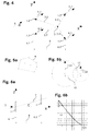
- Figure 1 shows a sketch for determining the repeller parameters: the repeller 1 comprises a wing 1.1 and an axis of rotation.
- the wing 1.1 in this example and in the projection shown here on the plane perpendicular to the axis of rotation, has the shape of a right-angled triangle.
- One of the acute angles of this triangle is at the center 1.2 of the repeller.
- the rotation thing pierces the paper plane at the center 1.2.
- the other pointed corner of the triangle is the outermost point 1.11 of the wing 1.1.
- the extreme point 1.11 describes, when rotating around the axis of rotation, a circle, the repeller circle 1.4.
- the repeller circle 1.4 has a radius 1.3 which corresponds to the distance between the outermost point 1.11 of the wing 1.1 to the center 1.2.
- a wing 1.1 has several outermost points 1.11, the most forward of these several points can be used, for example.
- the center point 1.2 can always be defined as the intersection point of the axis of rotation through the repeller circuit 1.4.
- Figure 2 is a sketch to explain the different levels and positional relationships of the wind turbine.
- the wind turbine system shown comprises three repellers 1. Their center points represent the corners of a triangle: this triangle is the arrangement surface 7.1.
- the arrangement area 7.1 lies in the arrangement level 7.
- the repellers 1 each define repeller circles 1.4, which in turn lie in repeller levels 6.1 and 6.2.
- a repeller 1 lies in a front repeller level 6.1 and two repellers 1 in a rear repeller level 6.2.
- the repeller levels 6.1 and 6.2 are parallel to each other.
- the positional relationship "front” and "rear” results from the operating direction.
- the wind should blow in the operating direction in the direction designated x.
- the arrangement surface 7.1 has an axis of symmetry 7.2.
- the direction designated x runs along the axis of symmetry 7.2.
- An axis of rotation 3.1 penetrates the arrangement surface 7.1 on the axis of symmetry 7.2.
- the z-direction runs parallel to the axis of rotation 3.1 and points in the direction opposite to the perpendicular direction.
- the coordinate system used should be right-handed and have its origin in the center 1.2 of the repeller 1 in the front repeller plane 6.1.
- the Figures 3a-e show different examples of repeller arrangements. All arrangements are shown in the view on arrangement level 7. The Figures 3a-e all show the operating arrangement.
- Figure 3a shows the arrangement "triangle in the wind”: the repeller arrangement 2 comprises exactly three repellers 1.
- the repeller centers 1.2 are arranged in the form of an isosceles triangle.
- Repellers 1 all have the same radius.
- the arrangement surface 7.1 is an isosceles triangle.
- the triangle has an axis of symmetry 7.11.
- Repeller 1 is located in two repeller levels 6.1 and 6.2. There is a repeller 1 in the front repeller level 6.1 and two repellers in the rear repeller level 6.2.
- the center of gravity 4 is 2/3 of the height of the triangle, that is, the length of the axis of symmetry 7.11, measured from the tip, that is, the center of the front repeller 1.
- the intersection point 3 of the axis of rotation also lies on the axis of symmetry 7.11, namely in front of the center of gravity 4.
- FIG. 3b shows the arrangement "triangle against the wind”:
- the repeller arrangement is very similar to the arrangement "triangle against the wind”.
- the operational orientation is rotated by 180 °: the wind 5 now strikes the base of the triangle, that is to say the front repeller level 6.1, which now has two repellers 1.
- the center of gravity is now 1/3 the height of the triangle or 1/3 the length of the axis of symmetry 7.11.
- the intersection point 3 of the axis of rotation lies on the axis of symmetry 7.11 and in front of the center of gravity 4.
- Figure 3c shows a further repeller arrangement 2.
- the arrangement surface 7.1 has the shape of a symmetrical trapezoid, the smaller of the two parallel sides facing the wind 5.
- the repellers 1 all have the same radius.
- the repellers 1 are arranged symmetrically.
- a repeller 1 lies in the middle between two further repellers 1.
- the axis of symmetry 7.11 runs parallel to the wind direction 5.
- the intersection point 3 of the axis of rotation through the arrangement surface lies in front of the center of gravity 4.
- FIG. 3d shows a further repeller arrangement 2.
- the arrangement surface 7.1 has the shape of a hexagon.
- the repeller arrangement 2 comprises a total of seven repellers 1.
- the repellers 1 are arranged on a total of three repeller levels 6.1, 6.2 and 6.3.
- the distance between the front repeller level 6.1 and the middle repeller level 6.2 is equal to the distance between the middle repeller level 6.2 and the rear repeller level 6.3.
- the arrangement surface 7.1 has an axis of symmetry 7.11 which runs parallel to the wind direction 5.
- Another axis of symmetry of the hexagon runs in the middle repeller level 6.2. However, this is not the axis of symmetry according to the invention through which the axis of rotation passes. Assuming that all repellers 1 have the same radius, the center of gravity 4 lies precisely at the center of the middle repeller 1 of the middle repeller level 6.2. The intersection point 3 of the axis of rotation lies in front of the load center of gravity 4, specifically on the axis of symmetry 7.11 between the front repeller level 6.1 and the middle repeller level 6.2.
- Figure 3e shows a repeller arrangement 2 of the type "triangle in the wind". It comprises three repellers 1, the arrangement surface 7.1 of which represents an isosceles triangle, the tip of which points into the wind 5.
- the front repeller level 6.1 is parallel to the rear repeller level 6.2.
- a repeller 1 is located on the front repeller level 6.1, and two repellers 1 are located on the rear repeller level 6.2.
- the two repellers 1 of the rear repeller level 6.2 have the same radius r2.
- the repeller 1 of the front repeller level 6.1 has the radius r1.
- the radius of the repeller 1 of the front repeller level 6.1 is twice as large as the radius of one of the repellers 1 of the rear repeller level 6.2.
- intersection point 3 of the axis of rotation lies in front of the center of gravity 4.
- Figure 4 shows a sketch for the calculation of the torque.
- This sketch shows the xy plane as in Figure 2 was introduced and a total of four centers 1.2 arranged symmetrically about the x-axis.
- the y-axis lies in the front repeller level 6.1 and the x-axis in the arrangement plane.
- the front repeller level 6.1 and the rear repeller level 6.2 are at a distance 8 from one another.
- intersection point 3 lies on the x axis by choice of the coordinate system and therefore has the coordinates (p, 0.0).
- Any center with index i lies in the x-y plane and therefore has the coordinates (xi, yi, 0).
- M z . i F i x i - p sin a - y i cos a
- Mz In order to generate a rotation which leads to the symmetry axis of the arrangement including the angle a with the x axis, Mz should be positive.
- Figure 5a is to show the concept of the convex hull 9: A lot of points are shown.
- the convex envelope 9 in the sense of this document is the line shown.
- the area enclosed by the line is the area in which all points lie and all connecting lines of these points. At the same time, the area is not larger than necessary to meet these conditions.
- Figure 5b illustrates the overlapping of two circles: Both circles have a center 1.2 and a radius 1.3.
- the triangle which is spanned by the two centers and the intersection of the circles, has the side lengths D, r1 and r2.
- triangles which are spanned by a center point and the two intersection points of the circles, must now be subtracted from this area. They are isosceles triangles with a half opening angle of ⁇ 1 or ⁇ 2 and a leg length of r1 or r2.
- Figure 6a shows a sketch to explain the possible deviation of the arrangement level from the vertical to the repeller levels.
- the arrangement level 7 should be essentially perpendicular to the repeller level. If it is not exactly vertical, the coordinate system should preferably be attached to the repeller plane and not to the arrangement plane: In case of doubt, the x-axis is therefore perpendicular to the repeller plane, even if arrangement plane 7 deviates slightly from it.
- the arrangement level should be aligned in such a way that there is still a shading effect. That in the case of wind parallel to the x-y plane, a front repeller or a front wind obstacle should be able to shade a rear repeller or a rear wind obstacle.
- Figure 6a shows such an arrangement: The projection of the repeller arrangement on the xz plane is shown. One looks at the edges of the arrangement level 7 and the repeller levels 6.1 and 6.2, so that they appear here as mere lines. The arrangement level 7 deviates from the normal to the repeller levels 6.1 and 6.2 by the angle c. The distance 8 of the repeller levels 6.1 and 6.2 from one another is also shown.
- D / (2r) can be between 0 and 1.
- this expression is also used when estimating the shading effect. It is about S ⁇ r 2 the normalized shading in the case of two circles of equal size.
- Figure 7a explains the shadowing effect using the example of the "triangle in the wind" repeller arrangement.
- the arrangement surface is an isosceles triangle with an axis of symmetry 7.11.
- the wind direction 5 in the operating orientation is parallel to the axis of symmetry 7.11.
- the isosceles triangle of the arrangement surface has a half opening angle b and a height h, which is equal to the distance between the repeller planes 8.
- the repellers have a radius r. We assume here that the radii of all repellers 1 are the same.
- the angle between wind direction and axis of symmetry 7.11 should now increase.
- the angle between wind direction and axis of symmetry 7.11 is denoted by a.
- repeller C gets into the slipstream of repeller A.
- repeller C emerges from the slipstream again.
- repeller A then falls into the slipstream of repeller B. This happens between the angles a minA and a maxA .
- Figure 7b shows the same situation for the "triangle against the wind” arrangement: the sketch clearly shows that shading occurs at the same angles as in the "triangle against the wind” arrangement.
- Figure 8a shows the top view of the arrangement surface 7.1 of a repeller arrangement with 3 repellers 1 in the constellation "triangle in the wind": the wind direction 5 is in the operational orientation.
- the point of intersection of the axis of rotation 3.1 is equal to the center of gravity 4.
- the arrangement surface 7.1 has the shape of an isosceles triangle with a half opening angle b.
- the area 16 which is used by the repeller arrangement is a circle with the radius 16.1.
- Figure 8b shows the same view of a repeller arrangement of the constellation "triangle against the wind".
- the point of intersection of the axis of rotation 3.1 now lies clearly in front of the center of gravity 4, which is 1/3 the height of the triangle of the arrangement surface 7.1.
- the surface 16 that is used by the repeller arrangement is again a circle with the radius 16.1.
- the radius 16.1 is that in Figure 8a shown constellation larger than in the in Figure 8b shown constellation.
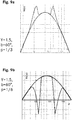
- Figure 9 shows the torque depending on the wind direction a.
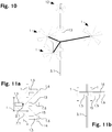
- Figure 10 shows a first wind turbine system according to the invention: Three repellers 1, each with six blades 1.1, are coupled to a repeller arrangement 2 on a common axis of rotation 3.1.
- the wind turbine system comprises a further repeller 12, which is not part of the repeller arrangement 2.
- FIG 11 shows a second embodiment of a wind turbine system according to the invention. This includes solar panels 14.
- Figure 11a shows the layout from below.
- Figure 11b shows the system from the side.
- the wind turbine plant comprises 3 repellers 1. These are each fastened with their bearings 1.5 to a support structure 15.
- the support structure has the shape of a "v”.
- the axles 1.6 driven by the repellers 1 protrude from the bearings 1.5 and are coupled to one another by belts.
- a generator unit 13 is located on the central axis 1.6.
- the center points of the repellers form an arrangement surface 7.1. This has the shape of an isosceles triangle.
- Solar panels 14 are located above the support structure 15, the bearings 1.5 and the axes 1.6.
- the solar panels 14 cover an approximately T-shaped surface.
- the axis of rotation 3.1 pierces the support structure 15 and the solar panels 14 in the area of the tip of the Vs.
- the arrangement surface 7.1 pierces the axis of rotation 3.1 at a distance of 2/3 of the height of the triangle, which represents the arrangement surface 7.1.
- repellers of the exemplary embodiments can also be replaced by suitable wind obstacles.
- geometries can be varied: Many examples relate to the triangular arrangement, but can also be realized with differently shaped arrangement surfaces.
- a wind turbine installation according to the invention can also be equipped with further repellers that do not belong to the repeller arrangement.
Abstract
Eine selbstausrichtende Windturbinenanlage umfasst eine Repelleranordnung (2) mit mindestens drei relativ zueinander starr angeordneten Windhindernissen. Mindestens zwei, insbesondere alle Windhindernisse sind Repeller (1). JederRepeller(1) weist mindestens einenFlügel(1.1) auf, der um eineRotationsachsedes jeweiligen Repellers (1) drehen kann. Ein Repeller (1) ist ein Windhindernis ist. Die Mittelpunkte (1.3) der mindestens drei Windhindernisse sind in mindestens zwei, parallel zueinander liegenden und voneinander beabstandetenRepellerebenen(6.1, 6.2, 6.3) angeordnet. Die Repellerebenen (6.1, 6.2, 6.3) stehen senkrecht zu den Rotationsachsen der Windhindernisse. Alle Repeller (1) der Repelleranordnung (2) sind gleich ausgerichtet. Die Mittelpunkte der mindestens drei Windhindernisse liegen in einer gemeinsamenAnordnungsebene(7). Die Anordnungsebene (7) steht im Wesentlichen senkrecht zu den Repeller-Ebenen (6.1, 6.2, 6.3).Eine konvexe Hülle (9) aller Mittelpunktealler Windhindernisse definiert eineAnordnungsfläche (7.1).Die Anordnungsfläche (7.1) weisteine Symmetrieachse(7.11) auf. Die Windturbinenanlage umfasst eineDrehachse (3.1),um welche die Repelleranordnung (2) drehbar ist, so dass die Selbstausrichtung ermöglicht wird. Der Durchstosspunkt der Drehachse (3.1) durch die Anordnungsfläche (7.1) liegt auf der Symmetrieachse (7.11) und zwar vor einem Belastungsschwerpunkt (4).A self-aligning wind turbine system comprises a repeller arrangement (2) with at least three wind obstacles which are rigidly arranged relative to one another. At least two, and in particular all, wind obstacles are repellers (1). Each repeller (1) has at least one wing (1.1) which can rotate about a rotational axis of the respective repeller (1). A repeller (1) is a wind obstacle. The center points (1.3) of the at least three wind obstacles are arranged in at least two repeller planes (6.1, 6.2, 6.3) that are parallel to one another and spaced apart from one another. The repeller planes (6.1, 6.2, 6.3) are perpendicular to the axes of rotation of the wind obstacles. All repellers (1) of the repeller arrangement (2) are aligned identically. The centers of the at least three wind obstacles lie in a common arrangement level (7). The arrangement plane (7) is essentially perpendicular to the repeller planes (6.1, 6.2, 6.3). A convex hull (9) of all centers of all wind obstacles defines an arrangement surface (7.1). The arrangement surface (7.1) has an axis of symmetry (7.11). The wind turbine system comprises a rotation axis (3.1) about which the repeller arrangement (2) can be rotated, so that self-alignment is made possible. The point of intersection of the axis of rotation (3.1) through the arrangement surface (7.1) lies on the axis of symmetry (7.11), specifically before a center of gravity (4).
Description
Die Erfindung betrifft eine selbstausrichtende Windturbinenanlage.The invention relates to a self-aligning wind turbine system.
Selbstausrichtende Windturbinenanalgen sind in von der Anwendung auf dem Wasser bekannt. Die
Die
Eine für die Nutzung an Land gedachte Windturbinenanlage offenbart unter anderem die
Eine aktive Windausrichtung, die eine Messung, eine Steuerung und Antriebe benötigt, bringt ein gewisses Ausfallpotential und muss gewartet werden. Zudem macht sie die Anlage in der Anschaffung teurer. Eine Selbstausrichtung durch eine Verankerung der Anlange ausserhalb des durch die Rotoren begrenzten Bereichs, ist aus gutem Grund nur für schwimmende Systeme vorgeschlagen worden: Die Lastverteilung wäre an einem Mast auf dem Land derart ungünstig, dass sich kaum eine sinnvolle Lebensdauer der Anlange erreichen lassen würde.Active wind alignment, which requires measurement, control and drives, has a certain potential for failure and must be maintained. It also makes the system more expensive to buy. For good reason, self-alignment by anchoring the system outside the area delimited by the rotors has only been proposed for floating systems: the load distribution would be on a mast in the countryside so unfavorable that it would hardly be possible to achieve a useful lifespan for the investment.
Aufgabe der Erfindung ist es, eine dem eingangs genannten technischen Gebiet zugehörende Windturbinenanlage zu schaffen, welche besonders wartungsarm ist und auf dem Land, insbesondere zur privaten Stromerzeugung und für Kleinerzeuger, genutzt werden kann.The object of the invention is to provide a wind turbine system belonging to the technical field mentioned at the outset, which is particularly low-maintenance and can be used on land, in particular for private power generation and for small producers.
Die Lösung der Aufgabe ist durch die Merkmale des Anspruchs 1 definiert. Gemäss der Erfindung umfasst die selbstausrichtende Windturbinenanlage eine Repelleranordnung mit mindestens drei relativ zueinander starr angeordneten Windhindernissen, von denen mindestens zwei, insbesondere alle Windhindernisse Repeller sind.The solution to the problem is defined by the features of
Jeder der Repeller der Repelleranordnung weist mindestens einen Flügel auf. Der Flügel kann sich um eine Rotationsachse des jeweiligen Repellers drehen. Der Repeller befindet sich in seiner Betriebsausrichtung, wenn er von vorne angeströmt wird. Ein vorderster und am weitesten von der Rotationsachse entfernter Punkt des genannten Flügels überstreicht bei einer Umdrehung um die Rotationsachse einen Kreis. Dieser Kreis definiert den Radius des Repellers. Der Mittelpunkt dieses Kreises liegt auf der Rotationsachse und definiert den Mittelpunkt des Repellers. Ein Repeller ist ein Windhindernis.Each of the repellers of the repeller arrangement has at least one wing. The wing can rotate about an axis of rotation of the respective repeller. The repeller is in its operating orientation when it is blown from the front. A foremost and most distant point of the said wing sweeps over a circle with one revolution around the axis of rotation. This circle defines the radius of the repeller. The center of this circle lies on the axis of rotation and defines the center of the repeller. A repeller is a wind obstacle.
Ein Windhindernis, welches zu der Repelleranordnung gehört und welches kein Repeller ist, ist derart geformt und angeordnet, dass in einer Konfiguration in der der Wind die Repeller der Repelleranordnung von vorne anströmt, seine dem Wind zugewandte Fläche rotationssymmetrisch ist. Die Symmetrieachse verläuft in Windrichtung und definiert die Rotationsachse des Windhindernisses. Die Rotationsachse des Windhindernisses durchstösst das Windhindernis in seinem Mittelpunkt. Der Mittelpunkt des Windhindernisses ist als vorderster, gemeinsamer Punkt von Windhindernis und Rotationsachse des Windhindernisses definiert.A wind obstacle which belongs to the repeller arrangement and which is not a repeller is shaped and arranged in such a way that in a configuration in which the wind flows against the repeller of the repeller arrangement from the front, its surface facing the wind is rotationally symmetrical. The axis of symmetry runs in the wind direction and defines the axis of rotation of the wind obstacle. The axis of rotation of the wind obstacle pierces the wind obstacle at its center. The center of the wind obstacle is defined as the foremost, common point of the wind obstacle and the axis of rotation of the wind obstacle.
Die Mittelpunkte der mindestens drei Windhindernisse der Repelleranordnung sind in mindestens zwei, parallel zueinander liegenden und voneinander beabstandeten Repellerebenen angeordnet. Dabei stehen die Repellerebenen senkrecht zu den Rotationsachsen der Windhindernisse, insbesondere zu den Rotationsachsen der Repeller. Alle Repeller der Repelleranordnung sind gleich ausgerichtet.The centers of the at least three wind obstacles of the repeller arrangement are in at least two, parallel to one another and spaced apart Repeller levels arranged. The repeller planes are perpendicular to the axes of rotation of the wind obstacles, in particular to the axes of rotation of the repellers. All repellers in the repeller arrangement are aligned identically.
Die Mittelpunkte der mindestens drei Windhindernisse liegen in einer gemeinsamen Anordnungsebene. Die Anordnungsebene steht im Wesentlichen senkrecht zu den Repellerebenen. Die konvexe Hülle aller Mittelpunkte aller Windhindernisse der Repelleranordnung definiert eine Anordnungsfläche.The centers of the at least three wind obstacles lie in a common arrangement level. The arrangement level is essentially perpendicular to the repeller levels. The convex hull of all centers of all wind obstacles of the repeller arrangement defines an arrangement surface.
Die Anordnungsfläche ist spiegelsymmetrisch und weist daher eine Symmetrieachse auf. Die Symmetrieachse verläuft im Wesentlichen parallel zu den Rotationsachsen.The arrangement surface is mirror-symmetrical and therefore has an axis of symmetry. The axis of symmetry runs essentially parallel to the axes of rotation.
Die Windturbinenanlage umfasst weiter eine Drehachse. Um diese Drehachse ist die Repelleranordnung drehbar, so dass die Selbstausrichtung möglich ist.The wind turbine system also includes an axis of rotation. The repeller arrangement can be rotated about this axis of rotation, so that self-alignment is possible.
Der Durchstosspunkt der Drehachse durch die Anordnungsfläche liegt dabei auf der Symmetrieachse und vor dem Belastungsschwerpunkt. Der Belastungsschwerpunkt ist der mit dem Strömungswiderstand der Windhindernisse der Repelleranordnung gewichtete Schwerpunkt.The point of intersection of the axis of rotation through the arrangement surface lies on the axis of symmetry and in front of the center of gravity of the load. The center of gravity is the center of gravity weighted with the flow resistance of the wind obstacles of the repeller arrangement.
"Starr zueinander angeordnet" soll hier und im Folgenden bevorzugt, sofern nichts anderes geschrieben wird, bedeuten, dass die Mittelpunkte der Repeller und gegebenenfalls der Windhindernisse und die Rotationsachsen der Repeller und gegebenenfalls der Windhindernisse sich nicht gegeneinander verschieben oder verdrehen können. Es soll dabei aber dennoch eine gewissen Elastizität der Anordnung möglich sein, die es erlaubt ungewöhnlich grosse Kräfte durch eine kurzzeitige Verformung der Anordnung aufzunehmen. Ausserdem schliesst die starre Anordnung es nicht aus, dass sich die Repellerflügel drehen können und dass sich die Anordnung als Ganzes drehen und gegebenenfalls auch verschieben lässt. Auch andere Windhindernisse als Repeller die Teil der Anordnung sind sollen gewisse Bewegungen und Verformungen machen können, obwohl sie starr angeordnet sind, wenn nur ihr Mittelpunkt und ihre Rotationsachse an einer, gegenüber den anderen Teilen der Anordnung, fixen Position und in einer festen Ausrichtung bleibt.Unless otherwise stated, “rigidly arranged to one another” should preferably mean here and below that the centers of the repellers and possibly the wind obstacles and the axes of rotation of the repellers and possibly the wind obstacles cannot shift or twist against one another. However, it should still be possible to have a certain elasticity of the arrangement, which allows unusually large forces to be absorbed by a brief deformation of the arrangement. In addition, the rigid arrangement does not rule out the fact that the repeller blades can rotate and that the arrangement as a whole can be rotated and possibly also shifted. Wind obstacles other than repellers that are part of the arrangement should also be able to make certain movements and deformations, although they are rigidly arranged if only their center point and their axis of rotation remain in a fixed position and in a fixed orientation relative to the other parts of the arrangement.
Die Ausrichtung eines Repellers ist die Lage seiner Rotationsachse in Bezug auf die Windrichtung.The orientation of a repeller is the position of its axis of rotation in relation to the wind direction.
Die Betriebsausrichtung eines Repellers ist bevorzugt diejenige Ausrichtung im Wind bei der der Repeller am effizientesten ist, d.h. dem Wind die meiste Energie entzieht.The operational orientation of a repeller is preferably the orientation in the wind at which the repeller is most efficient, i.e. draws most of the energy from the wind.
Durch die Betriebsausrichtung der Repeller der Repelleranordnung definiert, wo bei der Anordnung "vorne" liegt.The operational orientation of the repeller of the repeller arrangement defines where the arrangement lies "in front".
Unter "konvexer Hülle" versteht dieses Dokument den Rand der konvexen Hülle im mathematischen Sinne.By "convex hull" this document means the edge of the convex hull in the mathematical sense.
Die Definition einer konvexen Hülle im mathematischen Sinn ist folgende:
- Eine Menge von Punkten in der Ebene heißt konvex, wenn sie mit je zwei Punkten auch deren Verbindungsstrecke enthält.
- Gegeben sei eine Menge M von Punkten in der Ebene. Die konvexe Hülle im mathematischen Sinn von M ist die kleinste konvexe Menge, in der M enthalten ist.
- A set of points in the plane is called convex if it also contains the connecting route with two points each.
- Given a set M of points in the plane. The convex hull in the mathematical sense of M is the smallest convex set in which M is contained.
Bei konvexen Hülle, also dem Rand der konvexen Hülle im mathematischen Sinn, handelt sich also um eine in sich geschlossene Kurve ohne konkave Abschnitte. Stellt man sich die Mittelpunkte als Nägel vor, die in einem Brett stecken, dann erhält man die konvexe Hülle, also den Rand der konvexen Hülle im mathematischen Sinne, indem man ein Gummiband um die Nägel spannt.The convex hull, i.e. the edge of the convex hull in the mathematical sense, is a self-contained curve without concave sections. If you imagine the center points as nails, which are stuck in a board, you get the convex envelope, i.e. the edge of the convex envelope in the mathematical sense, by stretching a rubber band around the nails.
Die Anordnungsfläche umfasse alle und nur alle Punkte der konvexen Hülle im mathematischen Sinne.The arrangement surface includes all and only all points of the convex hull in the mathematical sense.
Die Symmetrieachse einen Fläche soll gemäss der folgenden, üblichen Definition zu verstehen sein:
Die Fläche ist achsensymmetrisch, falls es eine Gerade gibt, so dass es zu jedem Punkt P der Fläche einen weiteren (eventuell mit P identischen) Punkt P' der Fläche gibt, so dass die Verbindungsstrecke [PP'] von dieser Geraden rechtwinklig halbiert wird. Diese Gerade wird dann Symmetrieachse genannt. The axis of symmetry of a surface should be understood according to the following common definition:
The surface is axisymmetric if there is a straight line, so that for each point P of the surface there is a further point P 'of the surface (possibly identical with P), so that the connecting path [PP'] is halved at right angles by this straight line. This line is then called the axis of symmetry.
Die Drehachse ist hier eine geometrische Achse und nicht zwingend eine reale, durchgehende Achse. Es wäre beispielsweise denkbar, dass die Repelleranordnung auf einem zylinderartigen Turm mit einem Kreis- oder Polygonquerschnitt gelagert ist, der sich und die auf ihm gelagerte Repelleranordnung um Ganzen gegenüber dem Boden um die Drehachse drehen kann.The axis of rotation is a geometric axis here and not necessarily a real, continuous axis. It would be conceivable, for example, that the repeller arrangement is mounted on a cylinder-like tower with a circular or polygonal cross section, which can rotate about the axis of rotation and the repeller arrangement mounted thereon in relation to the ground.
Der Durchstosspunkt der Drehachse durch die Anordnungsfläche ist also derjenige Punkt der Anordnungsfläche, der bei dem Vorgang der Selbstausrichtung in den Wind seine Position gegenüber dem Boden und der Umgebung nicht verändert.The point of intersection of the axis of rotation through the arrangement surface is therefore the point on the arrangement surface which does not change its position in relation to the ground and the environment during the process of self-alignment in the wind.
Der Belastungsschwerpunkt der Mittelpunkt aller Windhindernisse der Repelleranordnung berechnet sich wie folgt:
Ein zweidimensionales kartesisches Koordinatensystem wird so gewählt, dass die Anordnungsfläche sich damit vollständig beschreiben lässt. Die Repelleranordnung soll N Windhindernisse mit je einem Mittelpunkt umfassen. Diese N Mittelpunkte liegen jeweils bei (xi, yi), wobei die Mittelpunkt fortlaufend durchnummeriert werden. Der Strömungswiderstand jedes Windhindernisses in seiner Betriebsausrichtung sei beispielsweise durch das Produkt von seinem cw-Wert und seiner Bezugsfläche A gegeben. Der Gewichtungsfaktor gi ergibt sich dann aus der Bedingung, dass das arithmetische Mittel der Gewichtungsfaktoren gleich 1 sein soll: ![]()
![]()
![]()
![]()
A two-dimensional Cartesian coordinate system is selected so that the arrangement area can be completely described. The repeller arrangement should include N wind obstacles, each with a center point. These N center points each lie at (x i , y i ), the center points being numbered consecutively. The flow resistance of each wind obstacle in its operational orientation is given, for example, by the product of its c w value and its reference area A. The weighting factor g i then results from the condition that the arithmetic mean of the weighting factors should be 1: ![]()
![]()
![]()
![]()
Die Anordnungsebene steht im Wesentlichen senkrecht zu den Repellerebenen und die Symmetrieachse verläuft im Wesentlichen parallel zu den Rotationsachsen. Diese Merkmale sollen derart verstanden werden, dass eine Abweichung vom geforderten Winkel zulässig ist, bei der es weiterhin zu einer relevanten Verschattung der Windhindernisse in einer hinteren Repellerebene durch Windhindernisse in einer vorderen Repellerebene kommen kann. Der Winkel zwischen der Senkrechten auf den Repellerebenen und der Anordnungsebene beziehungsweise zwischen den Rotationsachsen und der Symmetrieachse sollte daher zwischen 0° und arctan((R1max+R2max)/D) liegen. R1max ist dabei der grösste Radius eines Windhindernisses in einer vorderen Repellerebene und R2max ist der grösste Radius eines Windhindernisses in einer hinteren Repellerebene und D ist der Abstand zwischen den beiden betrachteten Repellerebenen. Bevorzugt liegt der Winkel zwischen der Senkrechten auf den Repellerebenen und der Anordnungsebene, beziehungsweise zwischen den Rotationsachsen und der Symmetrieachse zwischen 0° und arctan(0.4*(R1max+R2max)/D), besonders bevorzugt sogar nur zwischen 0° und arctan(0.16*(R1max+R2max)/D).The arrangement plane is essentially perpendicular to the repeller planes and the axis of symmetry runs essentially parallel to the axes of rotation. These features are to be understood in such a way that a deviation from the required angle is permissible, at which there can still be a relevant shading of the wind obstacles in a rear repeller plane by wind obstacles in a front repeller plane. The angle between the vertical on the repeller planes and the The arrangement level or between the axes of rotation and the axis of symmetry should therefore lie between 0 ° and arctan ((R1max + R2max) / D). R1max is the largest radius of a wind obstacle in a front repeller plane and R2max is the largest radius of a wind obstacle in a rear repeller plane and D is the distance between the two repeller planes considered. The angle between the vertical on the repeller planes and the arrangement plane, or between the axes of rotation and the axis of symmetry, is preferably between 0 ° and arctan (0.4 * (R1max + R2max) / D), particularly preferably only between 0 ° and arctan (0.16 * (+ r1max R2max) / D).
Es wurde überraschenderweise herausgefunden, dass es auch bereits dann zu einer zuverlässigen Selbstausrichtung kommt, wenn die Drehachse im Bereich zwischen den Repellern angeordnet ist. Damit das für die Selbstausrichtung notwendige Drehmoment bei einer solchen Anordnung aber genügend ausgeprägt ist, sollte es bei nicht optimaler Ausrichtung der Anlage zu einer Windverschattung einzelner Repeller kommen. Da die Drehachse im Bereich zwischen den Repellern angeordnet ist, können die Lasten der Repelleranordnung und weiterer Teile der Windturbinenanlage derart verteilt werden, dass Träger und Lager nicht übermässig belastet werden.Surprisingly, it was found that there is reliable self-alignment even when the axis of rotation is arranged in the area between the repellers. In order for the torque required for self-alignment to be sufficiently pronounced in such an arrangement, individual repellers should be shaded from the wind if the system is not optimally aligned. Since the axis of rotation is arranged in the area between the repellers, the loads on the repeller arrangement and other parts of the wind turbine system can be distributed in such a way that the carrier and bearing are not excessively loaded.
Durch die Windverschattung sinkt der Winddruck auf das verschattete Windhindernis, während er auf den anderen Windhindernissen im Wesentlichen gleich bleibt. Durch die Ungleichverteilung der Kräfte tritt ein Drehmoment auf. Bei der anspruchsgemässen Wahl des Durchstosspunktes der Drehachse und nicht zu grossen Sprüngen in der Windrichtung ist das Vorzeichen des Drehmoments so, dass die Repelleranordnung sich wieder in den Wind ausrichtet.Due to the wind shading, the wind pressure on the shaded wind obstacle drops, while it remains essentially the same on the other wind obstacles. Torque occurs due to the uneven distribution of forces. When the penetration point of the axis of rotation is selected as required and the jumps in the wind direction are not too large, the sign of the torque is such that the repeller arrangement aligns itself in the wind again.
Die resultierende Windturbinenanlage weist somit eine lange Lebensdauer auf und benötigt keine speziellen Antriebe oder Steuerungen um sich in den Wind auszurichten. Sie ist daher besonders wartungsarm.The resulting wind turbine system therefore has a long service life and does not require any special drives or controls to align itself in the wind. It is therefore particularly low-maintenance.
Im Folgenden wird das Funktionsprinzip mit einigen Beispielrechnungen illustriert.The principle of operation is illustrated below with some sample calculations.
Auf jedes Windhindernis wirkt eine Winddruckkraft von F (cos(a), sin(a)), wobei a die in Uhrzeigersinn gemessene Abweichung der Windrichtung von der für den Betrieb idealen Windrichtung ist. Das Koordinatensystem sei so gewählt, dass die Symmetrieachse auf der x-Achse verläuft und die Anordnungsfläche in der x-y Ebene liegt. Auch der Durchstosspunkt der Drehachse liegt auf der Symmetrieachse und hat daher die Koordinaten (p, 0).A wind pressure force of F (cos (a), sin (a)) acts on each wind obstacle, where a is the clockwise deviation of the wind direction from that which is ideal for operation Is wind direction. The coordinate system is chosen so that the axis of symmetry runs on the x-axis and the arrangement surface lies in the xy plane. The point of intersection of the axis of rotation also lies on the axis of symmetry and therefore has the coordinates (p, 0).
Betrachtet man die Windverschattung zunächst nicht, so stellt sich die Situation, unter der Annahme von Windhindernissen mit gleichem Strömungswiderstand, wie folgt dar:
Wegen der geforderten Symmetrie, gibt es für jeden Mittelpunkt eines Windhindernisses der Repelleranordnung bei (xi, yi) einen weiteren Mittelpunkt eines anderen Windhindernisses der Repelleranordnung bei (xi, -yi) oder der betreffende Mittelpunkt liegt auf der Symmetrieachse wo yi gleich Null ist. Der Abstandvektor vom der Durchstosspunkt der Drehachse zu jedem der Windhindernisse ist r=(xi-p, yi). Da die Betrachtung im zweidimensionalen Raum ist, ist nur die z-Komponente des Drehmoments ungleich Null. Sie ist ![]()
![]()
![]()
![]()
Because of the required symmetry, for each center point of a wind obstacle of the repeller arrangement at (x i , y i ) there is a further center point of another wind obstacle of the repeller arrangement at (x i , -y i ) or the relevant center point lies on the symmetry axis where y i is zero. The distance vector from the point of intersection of the axis of rotation to each of the wind obstacles is r = (x i -p, y i ). Since the observation is in two-dimensional space, only the z component of the torque is non-zero. she is ![]()
![]()
![]()
![]()
Aus dieser Betrachtung folgt zwar einerseits, dass auch ohne Abschattung eine gewisse Selbstausrichtung geschieht, andererseits ist das Drehmoment für der Durchstosspunkte der Drehachse in der Nähe des Schwerpunktes aber vergleichsweise klein. Um dies zu verdeutlichen, setzen wir ![]()
![]()
Die vorliegende Anlange geht daher einen dritten Weg und ändert die Grundannahme der oben beschriebenen Rechnung: Die auf die Windhindernisse wirkende Kraft ändert sich in Abhängigkeit der Windrichtung und zwar nicht nur mit dem Sinus-Term der aus dem verschattungslosen Modell bekannt ist.The present annex therefore goes a third way and changes the basic assumption of the calculation described above: The force acting on the wind obstacles changes depending on the wind direction and not only with the sine term that is known from the shade-free model.
Die Situation mit Windhindernissen unterschiedlichen Strömungswiderstandes aber ohne Verschattung lässt sich analog betrachten. Wir führen einen Gewichtungsfaktor gi ein, der den Strömungswiderstand des Windhindernisses bei (xi,yi) passend gewichtet: F gi ist die bei a=0° auf das Windhindernis wirkende Kraft. Die Gewichtungsfaktoren gi werden dabei so gewählt, dass ihr arithmetisches Mittel gerade gleich 1 ist, also ![]()
![]()
![]()
![]()
![]()
![]()
![]()
![]()
![]()
![]()
![]()
![]()
![]()
![]()
![]()
![]()
Die Situation mit Verschattung lässt sich durch eine von a abhängigen Gewichtungsfaktor gi(a) darstellen. Die Gewichtungsfaktoren werden derart gewählt, dass bei a=0° G(a=0°)/N=1 ist. Ausserdem soll ![]()
![]()
![]()
![]()
Zur Illustration nehmen wir an, dass das Windhindernis mit Mittelpunkt (x2, y2) zwischen a=10° und a=80° derart stark abgeschattet wird, das gar kein Druck mehr auf es wirkt, d.h. ![]()
![]()
![]()
![]()
![]()
![]()
![]()
![]()
![]()
![]()
Für den allgemeineren Fall von ungleichen Windhindernissen und einer beliebigen, winkelabhängigen Gewichtung des Windhindernisses bei (x2, y2) ergibt sich durch analoge Überlegungen das resultierende Drehmoment Mz = F N sin(a) [xg - p + ![]()
![]()
![]()
![]()
Gemäss einer bevorzugten Ausführungsform sind alle Windhindernisse der Repelleranordnung Repeller.According to a preferred embodiment, all wind obstacles in the repeller arrangement are repellers.
Diese Ausführungsform entzieht dem auf die Repelleranordnung treffenden Wind besonders viel Energie und hat daher einen guten Wirkungsgrad.This embodiment draws a particularly large amount of energy from the wind hitting the repeller arrangement and therefore has a good efficiency.
In einer anderen Ausführungsform gibt es neben Repellern auch Windhindernisse in der Repelleranordnung.In another embodiment, in addition to repellers, there are also wind obstacles in the repeller arrangement.
Die Windhindernisse können beispielsweise durch Solarzellen gebildet werden oder durch Plexiglasscheiben.The wind obstacles can be formed, for example, by solar cells or by plexiglass panes.
Diese Ausführungsform erlaubt es die Selbstausrichtung bereits dann zu nutzen, wenn die Mittel für mehr als zwei Repeller fehlen. Auch kann die Anlage auf diese Art funktionsfähig gehalten werden, wenn ein Repeller ausfällt. Schliesslich kann durch den Einsatz von Solarzellen als Windhindernisse eine Stromversorgung auch zu Zeiten in denen kein Wind weht gegeben sein.This embodiment allows self-alignment to be used when the resources for more than two repellers are lacking. The system can also be kept operational in this way if a repeller fails. Finally, the use of solar cells as wind obstacles can provide a power supply even at times when there is no wind.
Gemäss einer bevorzugten Ausführungsform ist der Abstand der Mittelpunkte zweier beliebiger Repeller innerhalb einer Repellerebene grösser ist als die Summe der Radien der betrachteten Repeller. Dies ist in dieser Ausführungsform für alle Repeller der Repelleranordnung der Fall.According to a preferred embodiment, the distance between the centers of any two repellers within a repeller plane is greater than the sum of the radii of the repellers under consideration. In this embodiment, this is the case for all repellers of the repeller arrangement.
Eine solche Anordnung erlaubt es, dass die Repeller in ihrer Drehzahl unabhängig voneinander sein dürfen. Es kann also auf eine Steuerung zum Ausgleichen der Drehzahlen verzichtet werden. Auch kann so weitgehend verhindert werden, dass Wirbelbildung an einem Repeller in einer Repellerebene einen zweiten Repeller in derselben Repellerebene negativ beeinflusst.Such an arrangement allows the repellers to be independent of one another in terms of their speed. There is therefore no need for a control to compensate for the speeds. It can also be largely prevented that vortex formation on a repeller in one repeller level negatively influences a second repeller in the same repeller level.
Repeller lassen sich auch so anordnen, dass die Flügel "ineinander" greifen: Einen Punkt in der Mitte zwischen zwei derart angeordneten, gleichgrossen Repellern passieren also Flügel beider Repeller und zwar, wenn diese die gleiche Anzahl Flügel aufweisen, immer abwechslungsweise. Eine solche Anordnung ist besonders kompakt.Repellers can also be arranged in such a way that the wings "interlock": A point in the middle between two repeaters of the same size arranged in this way, wings of both repellers pass alternately, if they have the same number of wings. Such an arrangement is particularly compact.
In einer Ausführungsform sind mindestens zwei Repeller der Repelleranordnung aneinander drehzahlgekoppelt.In one embodiment, at least two repellers of the repeller arrangement are speed-coupled to one another.
Drehzahlgekoppelte Repeller sollen derart miteinander verbunden sein, dass ihre Drehzahlen in einem festen Verhältnis zueinander stehen, bevorzugt sollen sie die gleiche Drehzahl aufweisen.Speed-coupled repellers should be connected to one another in such a way that their speeds are in a fixed relationship to one another, preferably they should have the same speed.
Dies verstärkt den Selbstausrichtungseffekt: Liegt ein Repeller im Windschatten eines anderen, so würde er ohne Drehzahlkopplung langsamer rotieren, da dem Wind bereits Energie entnommen wurde. Durch die Drehzahlkopplung wird er nun aber zu einer höheren Drehzahl "gezwungen". Der Repeller "saugt" sich also quasi nach vorne, was sich in einer weiteren Reduktion des Winddrucks äusserst, verglichen mit der Situation ohne Drehzahlkopplung. Umgekehrt wird aber auch der nicht verschattete, gekoppelte Repeller durch die Kopplung gebremst: Er dreht nur langsamer als er es ohne Kopplung tun würde. Der Luftwiderstand nimmt daher zu und somit auch der Winddruck auf ihn. Das drehmomenterzeugende Kräfteungleichgewicht wird verstärkt gegenüber dem ungekoppelten Fall.This reinforces the self-alignment effect: If one repeller is in the slipstream of another, it would rotate more slowly without speed coupling, since energy has already been drawn from the wind. The speed coupling now "forces" it to a higher speed. The repeller thus "sucks" itself forward, which manifests itself in a further reduction in the wind pressure compared to the situation without speed coupling. Conversely, the non-shaded, coupled repeller is also braked by the coupling: it only rotates more slowly than it would without a coupling. The air resistance therefore increases and with it the wind pressure on it. The torque-generating force imbalance is increased compared to the uncoupled case.
In einer Ausführungsform treiben mindestens zwei der Repeller der Repelleranordnung einen gemeinsamen Generator an.In one embodiment, at least two of the repellers of the repeller arrangement drive a common generator.
Dies hat den Vorteil, dass Kosten reduziert werden können, da die vergleichsweise teure Generatoreinheit weniger oft angeschafft werden muss. Ausserdem kann so eine möglichst günstige Massenverteilung innerhalb der Repelleranordnung realisiert werden.This has the advantage that costs can be reduced since the comparatively expensive generator unit does not have to be purchased as often. In addition, the most favorable possible mass distribution within the repeller arrangement can be realized in this way.
In einer Ausführungsform sind mindestens zwei der Repeller der Repelleranordnung drehzahlgekoppelt und treiben einen gemeinsamen Generator an.In one embodiment, at least two of the repellers of the repeller arrangement are speed-coupled and drive a common generator.
Neben den oben genannten Vorteilen einer Drehzahlkopplung und eines gemeinsamen Generators hat diese Anordnung den Vorteil, dass die Getriebe zwischen den Repellerachsen und der Generatorachse besonders einfach gestaltet werden können.In addition to the above-mentioned advantages of a speed coupling and a common generator, this arrangement has the advantage that the gears between the repeller axes and the generator axis can be designed in a particularly simple manner.
In einer Ausführungsform ist mindestens ein Repeller der vorderen Repellerebene drehzahlgekoppelt mit mindestens einem Repeller einer der hinteren Repellerebenen. Die drehzahlgekoppelten Repeller treiben gemeinsam einen Generator an. Bevorzugt sind alle Repeller der Repelleranordnung aneinander drehzahlgekoppelt und treiben gemeinsam einen Generator an.In one embodiment, at least one repeller of the front repeller level is speed-coupled to at least one repeller of one of the rear repeller levels. The speed-coupled repellers jointly drive a generator. All are preferred Repellers of the repeller arrangement are speed-coupled to one another and jointly drive a generator.
Die Drehzahlkopplung zwischen Repellern zweiter Repellerebenen hat den Vorteil, dass es zu einer Windverschattung des Repellers der hinteren Repellerebene durch den mit ihm drehzahlgekoppelten Repeller der vorderen Repellerebene kommen kann. Da der vordere Repeller durch die Kopplung gegenüber seiner freien Umdrehungsgeschwindigkeit gebremst wird, nehmen sein Widerstand und damit die Effizienz seiner Windabschattungsfähigkeit zu. Der Windverschattungseffekt kann also deutlicher zum Tragen kommen.The speed coupling between repellers of second repeller levels has the advantage that the repeller of the rear repeller level can be shaded from the wind by the repeller of the front repeller level coupled to it. As the front repeller is braked by the coupling against its free rotation speed, its resistance and thus the efficiency of its wind shading ability increase. The wind shading effect can therefore be more pronounced.
Die Nutzung eines gemeinsamen Generators ist kosteneffiziert, erlaubt eine günstige Verteilung des Gewichtes und lässt sich dank der Drehzahlkopplung besonders einfach erreichen.The use of a common generator is cost-effective, allows a favorable distribution of the weight and is particularly easy to achieve thanks to the speed coupling.
In einer Ausführungsform liegen alle Mittelpunkte der Windhindernisse, insbesondere der Repeller, der Repelleranordnung auf der konvexen Hülle der Mittelpunkte aller Windhindernisse der Repelleranordnung.In one embodiment, all centers of the wind obstacles, in particular the repellers, of the repeller arrangement lie on the convex hull of the centers of all wind obstacles of the repeller arrangement.
Es gibt also kein Windhindernis, welcher zu Repelleranordnung gehört und abseits vom Rand, in der Anordnungsfläche liegt.There is therefore no wind obstacle that belongs to the repeller arrangement and is located away from the edge in the arrangement area.
Diese Ausführungsform hat den Vorteil, dass es nur wenig Störungen der Repeller untereinander gibt. Ausserdem kann die starre Verbindung zwischen den Repellern einfach erreicht werden und in der freien Anordnungsfläche ist Platz für andere Bauteile, wie beispielweise den Generator oder Solarpaneele.This embodiment has the advantage that there is little interference between the repellers. In addition, the rigid connection between the repellers can be easily achieved and there is space in the free arrangement area for other components, such as the generator or solar panels.
In einer anderen Ausführungsform liegen Windhindernisse der Repelleranordnung mit ihren Mittelpunkten auch innerhalb der Anordnungsfläche. Dies erlaubt eine kompakte Bauweise.In another embodiment, wind obstacles of the repeller arrangement with their center points also lie within the arrangement surface. This allows a compact design.
In einer Ausführungsform sind alle Repeller der Windturbinenanlage Teil der Repelleranordnung.In one embodiment, all the repellers of the wind turbine system are part of the repeller arrangement.
Dies hat den Vorteil, dass alle Repeller für die Selbstausrichtung genutzt werden können.This has the advantage that all repellers can be used for self-alignment.
In einer anderen Ausführungsform umfasst die Windturbinenanlage Repeller die nicht zur Repelleranordnung gehören.In another embodiment, the wind turbine system comprises repellers that do not belong to the repeller arrangement.
Nicht zur Repelleranordnung gehörende Repeller können beispielswiese ober- oder unterhalb der Anordnungsebene liegen oder ihre Anordnung ist nicht symmetrisch. Derartige Repeller können für Messungen oder für eine von der Repelleranordnung unabhängige Stromerzeugung genutzt werden. Die Ausrichtung solche Repeller kann in Abhängigkeit der Repelleranordnung geschehen oder sie können durch eigene Windfahnen oder Motoren ausgerichtet werden. Ausserdem kann es auch Repeller mit fester Ausrichtung in eine häufig vorkommende Windrichtung geben.Repellers not belonging to the repeller arrangement can, for example, be above or below the arrangement level or their arrangement is not symmetrical. Such repellers can be used for measurements or for power generation that is independent of the repeller arrangement. Such repellers can be aligned depending on the repeller arrangement, or they can be aligned using your own wind vanes or motors. There can also be repellers with a fixed orientation in a frequently occurring wind direction.
In einer bevorzugten Ausführungsform ist der Winkel zwischen einer Senkrechten auf die Repellerebene und jeder der Verbindungslinien zwischen dem Mittelpunkt eines beliebigen Repellers der ersten Repellerebene und dem Mittelpunkt eines beliebigen Repellers einer zweiten Repellerebene, die ungleich der der ersten Repellerebene ist, grösser als arctan((r1+r2)/h). Insbesondere ist dieser Winkel grösser ist als 3°+arctan((r1+r2)/h). r1 und r2 sind die Repellerradien der betrachteten Repeller. h ist der Abstand zwischen der ersten und der zweiten Repellerebene.In a preferred embodiment, the angle between a perpendicular to the repeller level and each of the connecting lines between the center of any repeller of the first repeller level and the center of any repeller of a second repeller level, which is not equal to that of the first repeller level, is greater than arctan ((r1 + r2) / h). In particular, this angle is greater than 3 ° + arctan ((r1 + r2) / h). r1 and r2 are the repeller radii of the repellers under consideration. h is the distance between the first and second repeller levels.
Betrachtet man die Repelleranordnung von vorne, so überlappen sich die Repeller in dieser Ausführungsform nirgendwo. Es kommt also bei a=0° zu keiner nennenswerten Verschattung eines Repellers durch einen anderen. Da es insbesondere an den Enden der Flügel zu Turbulenzen kommt und diese sich etwas ausweiten mit zunehmenden Abstand zum Repeller, kann es sinnvoll sein den Winkel zwischen Senkrechter auf die Repellerebene und der Verbindungslinie der Mittelpunkte grösser als 3°+arctan((r1+r2)/h) zu wählen: Damit sinkt die Gefahr, dass der hintere Repeller bei idealer Anströmung, also a=0°, in die vom vorderen Repeller verursachten Turbulenzen gerät.If the repeller arrangement is viewed from the front, the repellers do not overlap anywhere in this embodiment. So at a = 0 ° there is no significant shading of one repeller by another. As there is turbulence in particular at the ends of the wings and these widen somewhat with increasing distance from the repeller, it may make sense to make the angle between the perpendicular to the repeller level and the connecting line of the center points greater than 3 ° + arctan ((r1 + r2) / h): This reduces the risk that the rear repeller will get into the turbulence caused by the front repeller when the flow is ideal, i.e. a = 0 °.
In einer anderen Ausführungsform ist der Winkel zwischen einer Senkrechten auf die Repellerebene und zumindest eine einzelnen Verbindungslinie zweiter Mittelpunkte kleiner als arctan((r1+r2)/h). Für den Preis einer etwas geringeren Leistung kann so eine kompaktere Bauweise erreicht werden.In another embodiment, the angle between a perpendicular to the repeller plane and at least one individual connecting line between second centers is smaller than arctan ((r1 + r2) / h). A compact design can thus be achieved for the price of a somewhat lower power.
In einer Ausführungsform haben alle Repeller der Repelleranordnung, insbesondere alle Repeller der Windturbinenanlage, denselben Radius.In one embodiment, all repellers of the repeller arrangement, in particular all repellers of the wind turbine system, have the same radius.
Die Nutzung gleicher Bauteile an mehreren Orten in der Anlage erleichtert die Wartung und das Zurverfügungstellung von Ersatzteilen. Ausserdem lässt sich so ein gegebenes Volumen optimal genutzt werden, da auf Grund der Selbstausrichtung der der wechselnden Windrichtungen der grösste Repeller an verschiedenen Positionen relativ zur Umgebung sein kann und dieses gesamte Gebiet freigehalten werden muss.The use of the same components at several locations in the system simplifies maintenance and the provision of spare parts. In addition, a given volume can be used optimally, since due to the self-alignment of the changing wind directions, the largest repeller can be at different positions relative to the environment and this entire area must be kept clear.
In einer anderen Ausführungsform gib es Repeller unterschiedlicher Radien in einer Repelleranordnung. Dies kann einerseits ermöglichen, dass die Anlage für verschiedene Windstärken jeweils zumindest teilweise optimal arbeitet und andererseits kann die Selbstausrichtungsfunktion so optimiert werden, da ein grosser Repeller einen kleineren über einen weiteren Winkelbereich vollständig abdecken kann als dies mit zwei gleich grossen Repellern möglich wäre. gi(a)ist durch die Wahl der Repellerradien auf diese Art beeinflussbar.In another embodiment, there are repellers of different radii in a repeller arrangement. On the one hand, this can allow the system to work at least partially optimally for different wind strengths, and on the other hand, the self-alignment function can be optimized in such a way that a large repeller can completely cover a smaller one over a wider angular range than would be possible with two repellers of the same size. g i (a) can be influenced in this way by the choice of the repeller radii.
In einer Ausführungsform umfasst die Repelleranordnung genau drei Repeller. Bevorzugt umfasst die Windturbinenanlage genau drei Repeller.In one embodiment, the repeller arrangement comprises exactly three repellers. The wind turbine system preferably comprises exactly three repellers.
Wenn alle Windhindernisse Repeller sind, so handelt es sich bei dieser Ausführungsform um die erfindungsgemässe Ausführungsform mit den wenigsten Repellern. Dies hat neben einem einfachen Aufbau den Vorteil, dass es nur zu geringen Störungen der Repeller untereinander kommt. Die Anlage lässt sich mechanisch einfach realisieren und gut auf die gewünschten Eigenschaften anpassen.If all wind obstacles are repellers, then this embodiment is the embodiment according to the invention with the fewest repellers. In addition to a simple structure, this has the advantage that there is only slight interference between the repellers. The system is easy to implement mechanically and can be adapted well to the desired properties.
Eine Anlage mit drei Repellern und zwei Windhindernissen kann dann eingesetzt werden, wenn es für die gewünschte Selbstausrichtungsfunktion notwendig ist, weil beispielsweise eine Verstärkung über einen weiteren oder anderen Winkelbereich erwünscht ist als über die Repeller alleine erreichbar.A system with three repellers and two wind obstacles can be used if it is necessary for the desired self-alignment function because, for example, reinforcement over a wider or different angular range is desired than can be achieved using the repellers alone.
Eine Windturbinenanlage mit genau drei Repellern umfasst bevorzugt eine Repelleranordnung mit genau drei Repellern und hat damit die oben beschriebenen Vorteile. Der Verzicht auf weitere Repeller hat den Vorteil, dass die Anlange einfacher und günstiger ist und die Zusatzrepeller die Repeller der Repelleranordnung weder mechanisch noch strömungstechnisch behindern oder stören.A wind turbine system with exactly three repellers preferably comprises a repeller arrangement with exactly three repellers and thus has the advantages described above. Eliminating further repellers has the advantage that the process is easier and is cheaper and the additional repellers do not hinder or disturb the repellers of the repeller arrangement mechanically or fluidically.
In einer Ausführungsform sind genau ein Repeller der Repelleranordnung mit Radius r1 mit seinem Mittelpunkt in der vordersten Repellerebene und genau zwei Repeller der Repelleranordnung mit Radius r2 mit ihren Mittelpunkten in einer zweiten Repellerebene angeordnet. Die erste und die zweite Repellerebene haben den Abstand h voneinander, so dass die konvexe Hülle der Mittelpunkte ein gleichschenkliges Dreieck darstellt.In one embodiment, exactly one repeller of the repeller arrangement with radius r1 with its center in the foremost repeller plane and exactly two repellers of the repeller arrangement with radius r2 with their centers are arranged in a second repeller plane. The first and the second repeller plane have the distance h from each other, so that the convex hull of the center points represents an isosceles triangle.
Gemäss der Einführung ist das resultierende Drehmoment, wenn nur ein Repeller verdeckt werden kann, in seiner allgemeinsten Form folgendes: ![]()
![]()
In der Dreiecksanordnung, bei der die Spitze des Dreiecks in Betriebsausrichtung in den Wind zeigt, können von den Windrichtungen a zwischen 0° und 180° genau zwei Repeller verdeckt werden: Im Bereich mit a zwischen 0° und 90° kann der vorderste Repeller, hier mit Index 1 bezeichnet, den bei positiven y-Werten in der hinteren Repellerebene liegenden Repeller mit Index 3 verdecken. Im Bereich mit a zwischen 90° und 180° kann der bei negativen y-Werten in der hinteren Repellerebene liegenden Repeller mit Index den vorderen Repeller 1 verdecken.In the triangular arrangement, in which the tip of the triangle points in the direction of operation in the wind, exactly two repellers can be covered by the wind directions a between 0 ° and 180 °: In the area with a between 0 ° and 90 °, the front repeller, here with
Für die Z-Komponente des Drehmoments folgt also: 
Da die Repelleranordnung ausschliesslich Repeller umfasst, nehmen wir an, dass der cW-Wert aller Repeller gleich ist und sie sich nur in ihre Bezugsfläche A = πr 2 unterscheiden. Bei a=0° sind die Gewichtungen also folgende: ![]()
![]()
Die Koordinaten der Mittelpunkte sind (x 1,y 1) = (0,0), (x 2 ,y2 ) = (h, -h tan(b)), (x 3 ,y 3) = (h, h tan(b)).The coordinates of the center points are ( x 1 , y 1 ) = (0,0), ( x 2 , y 2 ) = ( h, -h tan ( b )), ( x 3 , y 3 ) = ( h, h tan ( b )).
Um die Abhängigkeit der Verschattung vom Winkel abzuschätzen, nehmen wir an, dass die Bezugsfläche des verschatteten Repellers um den verschatteten Teil abnimmt.In order to estimate the dependence of the shading on the angle, we assume that the reference surface of the shaded repeller decreases around the shaded part.
Die Schnittfläche zweier Kreise (mit den Radien r1 und r2) lässt sich wie folgt berechnen, wobei d der Abstand der beiden Mittelpunkte voneinander ist. Dabei sollte der arccos im Bogenmass sein. 
Hier ist d=h·||tan(a)| - tan(b)|, da h|tan(a)| die Position vom "Schatten" des Mittelpunktes des vorderen Repellers ist und h tan(b) die Position vom verschatteten Repeller.Here d = h · || tan ( a ) | - tan ( b ) |, since h | tan ( a ) | is the position of the "shadow" of the center of the front repeller and h tan ( b ) is the position of the shaded repeller.
Für d > r1+r2 ist S=0.For d> r1 + r2, S = 0.
Die Verschattung des Repellers 3 durch den Repeller 1 kommt daher nur für die folgenden Winkel vor: ![]()
![]()
Die Verschattung des Repellers 1 durch Repeller 2 kommt daher nur für die folgenden Winkel vor: ![]()
![]()
Für r1=r2=r und im Verhältnis der Gesamtkreisfläche πr 2 ausgedrückt, vereinfacht sich S(a) zu: 


Beispielhaft setzen nehmen wir hier an, dass r1=r2=1 und b=45° sei. Um kein Überlappen bei a=0° zu haben, soll h=cot(b) (r1+r2)=2*cot(45°)=2 sein. Der erste Repellermittelpunkt kann bei (0,0) sein, der zweite und dritte je bei (2,-2) und (2,2). Damit ergibt sich: ![]()

![]()
![]()
![]()

![]()
![]()
![]()
![]()
Durch die Abschattung gibt es, im Vergleich zum nicht-verschatteten Fall, eine Erhöhung des positiven Drehmomentes um a=0° herum. Die Erhöhung ist maximal bei a=b und 180°-b.Due to the shading, there is an increase in the positive torque by a = 0 ° compared to the unshaded case. The increase is maximal at a = b and 180 ° -b.
Für den Fall einer Dreiecksanordnung mit einer Drehachse, die genau im Belastungsschwerpunkt die Anordnungsebene durchstösst, ist das resultierende Drehmoment in dem Bereich positiv, in dem es zu einer Verschattung kommt. Es gibt wie im Fall ohne Verschattung, kein Drehmoment ausserhalb der Verschattungszone.In the case of a triangular arrangement with an axis of rotation which penetrates the arrangement plane precisely at the center of gravity of the load, the resulting torque is positive in the area in which shading occurs. As in the case without shading, there is no torque outside the shading zone.
Allgemeiner betrachtet sieht der Fall von 3 Repellern in einer Dreiecksanordnung, bei der die Spitze des Dreiecks im Betriebszustand in den Wind gerichtet ist, wie folgt aus.More generally, the case of 3 repellers in a triangular arrangement, in which the tip of the triangle is directed towards the wind in the operating state, looks as follows.
Die Repeller in der hinteren Repellerebene sollen den Durchmesser r2 haben, und der Repeller in der vorderen Repellerebene soll den Durchmesser r1 haben.The repellers in the rear repeller level should have the diameter r2, and the repellers in the front repeller level should have the diameter r1.
Ohne Einschränkung der Allgemeinheit sollen die drei Repeller wie folgt angeordnet und nummeriert sein: 
Der Abstand der Repellerebenen ist h = y(r 1 + r 2) cot(b)The distance between the repeller levels is h = y ( r 1 + r 2 ) cot ( b )
Der Abstand der Mittelpunkte der sich überschattenden Repeller ist: 


Der Repeller 3 wird im Winkelbereich arctan ![]()


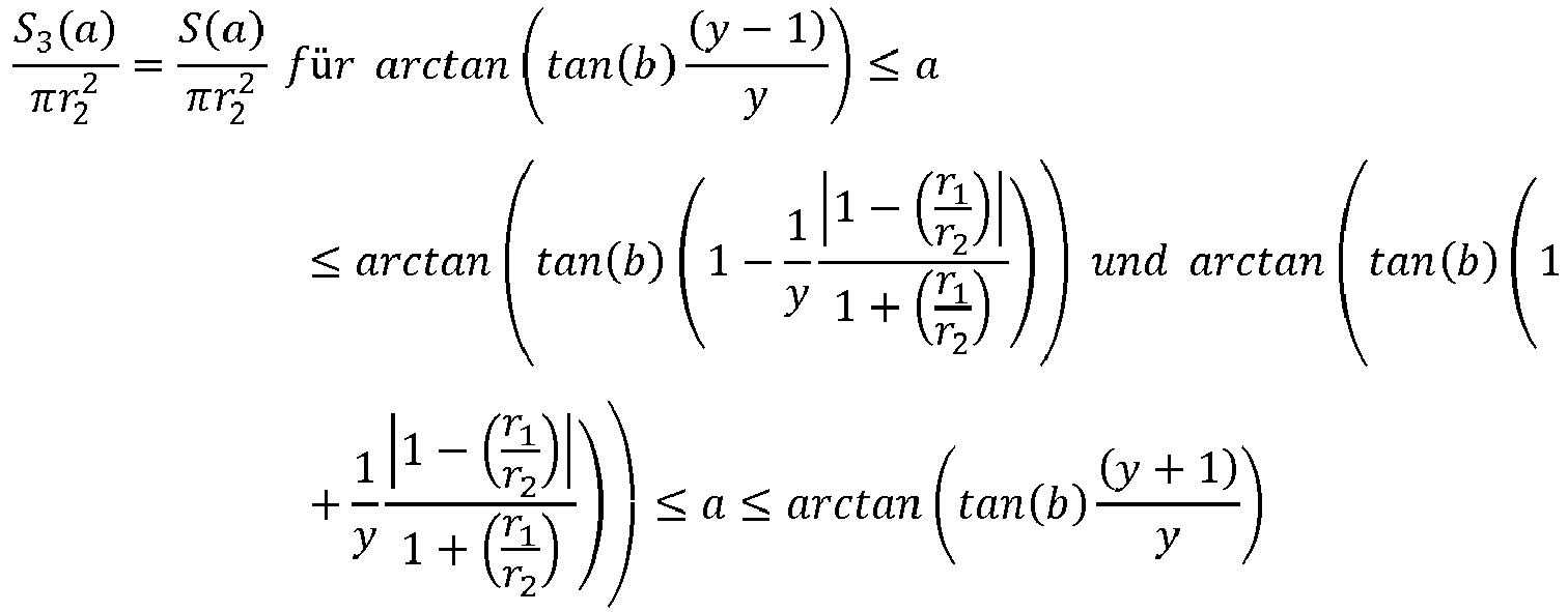
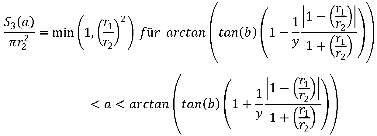
![]()
Der Repeller 1 wird im Winkelbereich ![]()
![]()

![]()
![]()
![]()
![]()
![]()
![]()
Für das Drehmoment ergibt sich: 


Dieser Ausdruck lässt sich besser verstehen, wenn man die Höhe h = y(r 1 + r 2)cot(b) des Dreiecks ausklammert: 
![]()
![]()
S3(a) ist nur für 0° ≤ a ≤ 90° ungleich 0. Der Tangens ist in diesem Bereich positiv. Der Ausdruck in der runden Klammer ist daher sicher positiv, solange 0° ≤ a < b und wird für grössere b negativ, wobei die Grenze von p/h abhängt. Für a > 90° ist S3(a) =0.S 3 (a) is not equal to 0 only for 0 ° ≤ a ≤ 90 °. The tangent is positive in this area. The expression in the parenthesis is therefore definitely positive as long as 0 ° ≤ a < b and becomes negative for larger b, the limit depending on p / h. For a> 90 °, S 3 (a) = 0.
S1(a) ist grösser oder gleich 0. Grösser als Null ist S1(a) bei Winkeln zwischen 90° und 180°.S 1 (a) is greater than or equal to 0. greater than zero S 1 (a) at angles between 90 ° and 180 °.
Der gesuchte Verstärkungseffekt der Selbstausrichtungsfunktion tritt also zwischen ![]()
![]()
![]()
![]()
Der Effekt ist am stärksten bei gleich grossen Repellern, also ![]()
![]()
![]()
![]()
![]()
![]()
![]()
![]()
![]()
![]()
In einer Ausführungsform wird der Abstand zweier Repellerebenen, der Radius des grössten Repellers in der hinteren Ebene, der durch einen Repeller in der vorderen Ebene abgeschattet werden kann und der der Durchstosspunkt der Drehachse derart gewählt, dass das Verhältnis des Drehmomentes mit Abschattungseffekt zum Drehmoment ohne Abschattungseffekt bei einer Anströmung von Wind mit einem Windwinkel grösser oder gleich 1.05 ist. Der Windwinkel ist gleich dem Winkel zwischen der Verbindungslinie vom abschattenden zum abgeschatteten Repeller und der Symmetrieachse.In one embodiment, the distance between two repeller planes, the radius of the largest repeller in the rear plane, which can be shaded by a repeller in the front plane and the penetration point of the axis of rotation is selected such that the ratio of the torque with shadowing effect to the torque without shadowing effect with a flow of wind with a wind angle greater than or equal to 1.05. The wind angle is equal to the angle between the connecting line from the shadowing to the shaded repeller and the axis of symmetry.
Damit der Verschattungseffekt deutlich zu spüren ist, sollte die durch die Verschattung erzeugte Amplitude signifikant sein im Vergleich zur unverschatteten Amplitude.So that the shading effect can be clearly felt, the amplitude generated by the shading should be significant compared to the unshaded amplitude.
Für das Drehmoment gilt: 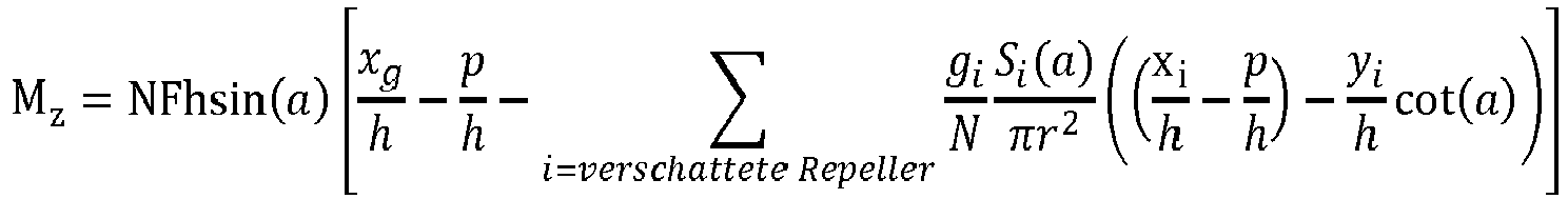
Die unverschattete Amplitude ist also: ![]()
![]()
Die verschattet Amplitude ist also: ![]()
![]()
![]()
![]()
Wir betrachtet das Verhältnis bei a=b. In diesem Fall betrifft die Verschattung einen Repeller in der hinteren Repellerebene und daher ist ![]()
![]()
![]()
![]()
Für das Verhältnis folgt daher: 
Nun fällt aber die Effizienz der Abschattung mit zunehmender Entfernung zwischen den Repellern ab. Wir nehmen an, dass diese Effizienz durch eine Exponentialfunktion approximiert werden kann: ![]()
![]()
Der Abstand der Repeller ist h/cos(b). In Einheiten von r also ![]()
![]()
Für die Effizienz der Abschattung folgt: ![]()
![]()
Für das Amplitudenverhältnis ergibt sich also: 
Im Fall eines "Dreiecks im Wind" mit 3 gleichen Repellern ist yi=h tan(b), N=3 und gi=1 und xg/h=2/3 und somit 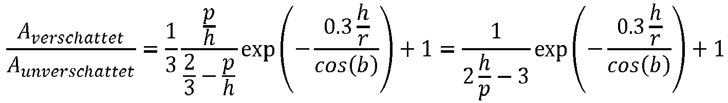
Bevorzugt liegt eine wirksame Abschattung genau dann vor, wenn ![]()

![]()
Gleichzeitig ist das Verhältnis h/r aber nach unten beschränkt, da eine Verschattung bei a=0° vermieden werden sollte: ![]()

![]()
Da für eine grossen Verschattungseffekt h/r möglichst klein sein sollte, ergibt sich das grösste Verschattungsverhältnis bei ![]()

![]()
Durch die Signifikanzforderung von ![]()

![]()
![]()
![]()
Bevorzugt liegt daher ![]()
![]()
Ist hingegen p/h gegeben, so ergibt die Signifikanzforderung eine Bedingung für den halben Öffnungswinkel: 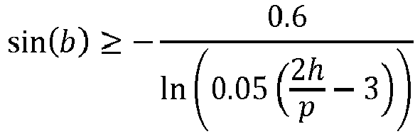
Die Ausdehnung des Dreiecks sollte daher bevorzugt folgendes sein: 
Bei b=45° ergibt sich also, dass 
![]()
![]()
Bei p/h=1/3 ergibt sich also ![]()
![]()

![]()
![]()
Gibt es eine bevorzugte Höhe des Dreiecks, beispielsweise h/r=3, so folgt, dass b=33.7° sein sollte und 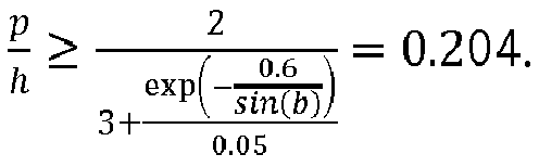
Diese Parameterkombinationen zeichnen sich jeweils dadurch aus, dass der Abschattungseffekt bei a=b signifikant ist und es bei a=0° keine Abschattung gibt.These parameter combinations are characterized by the fact that the shading effect is significant at a = b and there is no shading at a = 0 °.
In einer Ausführungsform einer selbstausrichtenden Windturbinenanlage sind genau zwei Repeller der Repelleranordnung mit Radius r2 mit ihren Mittelpunkten in der vordersten Repellerebene angeordnet und genau ein Repeller der Repelleranordnung mit Radius r1 ist mit seinem Mittelpunkt in einer zweiten Repellerebene angeordnet. Die konvexe Hülle der Mittelpunkte stellt ein gleichschenkliges Dreieck dar.In one embodiment of a self-aligning wind turbine system, exactly two repellers of the repeller arrangement with radius r2 are arranged with their centers in the foremost repeller plane and exactly one repeller of the repeller arrangement with radius r1 is arranged with its center in a second repeller plane. The convex hull of the center points represents an isosceles triangle.
Diese Ausführungsform unterscheidet sich von der vorherigen durch die Betriebsrichtung.This embodiment differs from the previous one in the operating direction.
Ohne Einschränkung der Allgemeinheit sollen die drei Repeller wie folgt angeordnet und nummeriert sein: ![]()
![]()
Der Abstand der Repellerebenen ist h = y(r 1 + r 2) cot(b)The distance between the repeller levels is h = y ( r 1 + r 2 ) cot ( b )
Der Abstand der Mittelpunkte der sich überschattenden Repeller ist: 
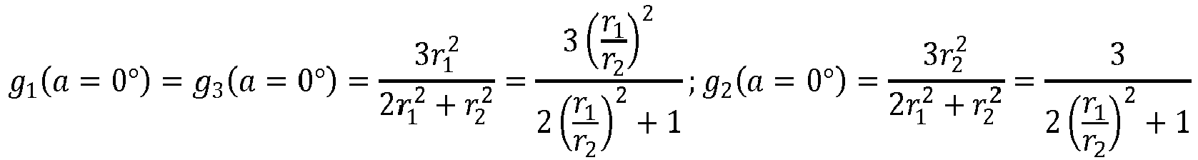


Der Repeller 2 wird im Winkelbereich arctan ![]()


![]()
Der Repeller 3 wird im Winkelbereich ![]()
![]()
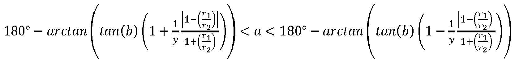
![]()
![]()

![]()
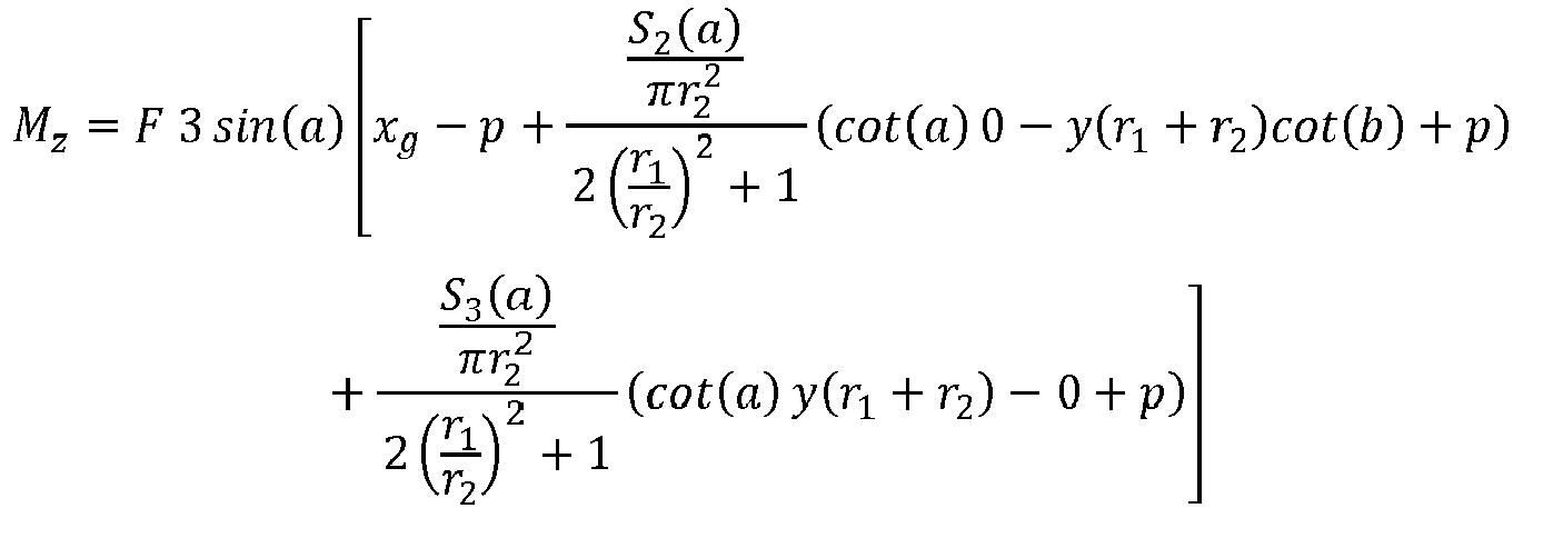
![]()
![]()
![]()
![]()
![]()
Dieser Ausdruck lässt sich besser verstehen, wenn man die Höhe h = y(r 1 + r 2)cot(b) des Dreiecks ausklammert: 

![]()
![]()
Da p/h < 1 ist, ist der S2 Beitrag immer negativ oder 0. S3 kann nur im Bereich zwischen 90° ≤ a ≤ 180° ungleich 0 sein und dort ist der tan(a) negativ, daher ist auch der S3 Anteil oft negativ und bei p/h =0 sogar immer.Since p / h <1, the S 2 contribution is always negative or 0. S 3 can only be non-0 in the range between 90 ° ≤ a ≤ 180 ° and there the tan (a) is negative, hence the S 3 Proportion often negative and even always with p / h = 0.
Die Abschattung verringert also das selbstausrichtende Drehmoment über weite Bereiche von a. Die Verminderung ist am deutlichsten bei ![]()
![]()
![]()
![]()
![]()
![]()
![]()
![]()
Die Abschattung kann also eingesetzt werden, wenn hohe Drehmomente vermieden werden sollen.The shading can therefore be used if high torques are to be avoided.
Diese Anordnung, die im Folgenden auch als "Dreieck gegen den Wind" bezeichnet wird, hat weiter den Vorteil einer guten Flächennutzung: Das Verhältnis der Anordnungsfläche zur Fläche die für die Selbstausrichtung der Repelleranordnung freigehalten werden muss, ist grösser als im Fall "Dreieck im Wind". Da die Anordnungsfläche kaum verschattet wird, kann sie mit Solarpaneelen bedeckt werden. Je grösser das Verhältnis der Anordnungsfläche für die Selbstausrichtung zur benötigten Fläche ist, desto besser wird die zur Verfügung stehende Fläche ausgenutzt.This arrangement, which is also referred to below as "triangle against the wind", has the further advantage of a good use of space: the ratio of the arrangement surface to the surface that must be kept free for the self-alignment of the repeller arrangement is greater than in the case of "triangle in the wind" ". Since the arrangement area is hardly shaded, it can be covered with solar panels. The greater the ratio of the arrangement area for self-alignment to the required area, the better the available area is used.
In einer Ausführungsform einer Windturbinenanlage mit genau drei Repellern mit Radius r, deren Mittelpunkte eine konvexe Hülle in Form eines gleichschenkligen Dreiecks haben, liegt der halbe Öffnungswinkel b des gleichschenkligen Dreiecks zwischen 10° und 50°, bevorzugt bei etwa 25°.In one embodiment of a wind turbine system with exactly three repellers with radius r, the center points of which have a convex shell in the form of an isosceles triangle, half the opening angle b of the isosceles triangle is between 10 ° and 50 °, preferably about 25 °.
Eine solche Anordnung hat den Vorteil, dass das Verhältnis von Drehmoment zu Trägheitsmoment sein Maximum bei vergleichsweise grossen Windrichtungswinkeln hat. Somit reagiert die Repelleranordnung bei grossen Abweichungen von der Soll-Windrichtung stärker als bei kleineren. Die Repelleranordnung ist so weniger nervös und richtet sich dennoch zügig selbst aus wenn es eindeutig notwendig ist.Such an arrangement has the advantage that the ratio of torque to moment of inertia has its maximum at comparatively large wind direction angles. The repeller arrangement thus reacts to large deviations from the target wind direction stronger than smaller ones. The repeller arrangement is less nervous and still aligns itself quickly if it is clearly necessary.
Die Repeller und gegebenenfalls die Windhindernisse sind diejenigen Lasten, auf die die Repelleranordnung nicht verzichten kann. Die Verbindungselemente zwischen ihnen, die die geforderte starre Verbindung herstellen, sind bevorzugt leicht im Vergleich zu den Repellern. Wir gehen daher hier von einer Fläche mit Punktmassen an den Orten der Mittelpunkte aus.The repellers and possibly the wind obstacles are the loads that the repeller arrangement cannot do without. The connecting elements between them, which establish the required rigid connection, are preferably light compared to the repellers. We are therefore assuming an area with point masses at the locations of the center points.
Das Trägheitsmoment bezüglich einer Drehachse am Punkt (p, 0), senkrecht zur Anordnungsfläche, ist bei N Punktmassen ![]()
![]()
Im Fall eines in den Wind gerichteten Dreiecks mit drei gleich grossen und gleich schweren Repellern befinden sich die Repeller und, damit gemäss unserer Annahme auch die Massenpunkte, bei (0,0), (h, h tan(b)) und (h, -h tan(b)). p soll irgendwo vor dem Belastungsschwerpunkt bei 2/3 h liegen. 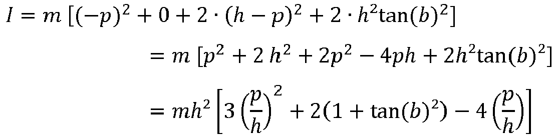
Bei gegebenen b befindet sich das p mit dem geringsten Trägheitsmoments am Massenschwerpunkt, also im Falle des Dreiecks bei p/h=2/3.Given b, the p with the lowest moment of inertia is at the center of mass, i.e. in the case of the triangle at p / h = 2/3.
Dort wo das Verhältnis von Drehmoment zu Trägheitsmoment besonders gross ist, ist auch die von Drehmoment erzeugte Beschleunigung besonders gross und somit die Selbstausrichtung besonders zügig.Where the ratio of torque to moment of inertia is particularly large, the acceleration generated by torque is also particularly large and thus self-alignment is particularly rapid.
Nur der Term des Drehmomentes der die Abschattung beschreibt, hängt von der Geometrie des Dreiecks ab. Daher betrachten wird hier nur diesen Term: ![]()
![]()
![]()


![]()
![]()
![]()
Es interessiert hier nur Bereich in dem 0°<a<90° ist. S1 (a) ist dort immer Null.The only area of interest here is 0 ° <a <90 °. S1 (a) is always zero there.
Das Trägheitsmoment ist, wie bereits oben erläutert, in diesem Fall: ![]()
![]()
Die Drehachse soll für diese Betrachtung bei p/h=2/3 liegen, also auf dem Massenschwerpunkt. Wir betrachten also die Situation mit dem kleinsten Trägheitsmoment.For this consideration, the axis of rotation should be p / h = 2/3, i.e. on the center of mass. So we consider the situation with the smallest moment of inertia.
Mit diesen Annahmen ist das Verhältnis des Drehmomentterms Mz*zum Trägheitsmoment I im Bereich von ![]()

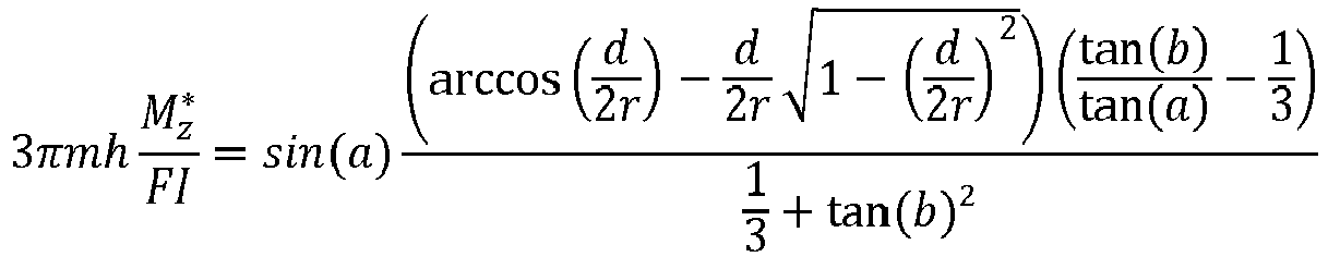
![]()
Weiter nehmen wir an, dass der Rotordurchmesser so gewählt ist, dass die Rotorkreise in der Projekton auf eine der Repellerebene sich gerade berühren, aber nicht schneiden. Das heisst, dass h tan(b) = 2r. Mit dieser Annahme ergibt sich aus der Definition von d(a) = dass ![]()
![]()
![]()
![]()
Die Ergebnisse zeigt die folgende Tabelle:
![]()
![]()
Repelleranordnungen, der Art "Dreieck mit Spitze im Wind", die stark auf Abweichungen reagieren, habe also Öffnungswinkel zwischen etwa 10° und etwa 50°, und insbesondere einen Öffnungswinkel von ca. 25°. Für eine starke Reaktion sollte in etwa das Maximum von ![]()
![]()
Um die stärkste Reaktion auf eine bestimmte Windrichtung zu haben, sollte der halbe Öffnungswinkel grösser sein als diese Windrichtung und bevorzugt gerade gleich dieser Windrichtung.In order to have the strongest reaction to a certain wind direction, half the opening angle should be larger than this wind direction and preferably just equal to this wind direction.
In einer Ausführungsform umfasst die selbstausrichtende Windturbinenanlage Solarpaneele die zumindest einen Teil der Anordnungsfläche bedecken. Bevorzugt bedecken die Solarpaneele einen Anteil von mehr als 80% der Anordnungsfläche. Bevorzugt sind die Solarpaneele oberhalb der Mittelpunkte der Repeller der Repelleranordnung und oberhalb von Verbindungselementen der Repeller der Repelleranordnung montiert. Bevorzugt sind die Solarpaneele in einem Bereich zwischen der Anordnungsebene und einer Parallelebene im Abstand vom grössten vorkommenden Radius eines Repellers der Repelleranordnung darüber montiert.In one embodiment, the self-aligning wind turbine system comprises solar panels that cover at least part of the arrangement area. The solar panels preferably cover a portion of more than 80% of the arrangement area. The solar panels are preferably mounted above the center points of the repellers of the repeller arrangement and above connecting elements of the repellers of the repeller arrangement. The solar panels are preferably mounted in an area between the arrangement level and a parallel plane at a distance from the largest occurring radius of a repeller of the repeller arrangement above.
"Oben" und "unten" sollen hier durch die Lotrichtung bestimmt sein und an der Windturbinenanlage im montierten Zustand festgestellt werden. Ein Lot, welches an der Windturbinenanlage im Betriebszustand befestigt ist, zeigt nach unten. Die Gegenrichtung zu "unten" ist "oben"."Above" and "below" are to be determined here by the direction of the solder and are to be determined in the assembled state on the wind turbine system. A solder, which is attached to the wind turbine system in the operating state, points downwards. The opposite direction to "below" is "above".
Die Bedeckung der Anordnungsfläche mit Solarpaneelen erlaubt eine Stromproduktion in Zeiten mit wenig Wind aber Sonneneinstrahlung. Insbesondere in Verbindung mit langsam drehenden Repellern kann diese Kombination eingesetzt werden: Langsam drehende Repeller versetzen auch die sie durchströmende Luft nur in eine geringe Drehung. Die Vertikalkomponente der Luftbewegung ist also vergleichsweise klein. Hindernisse wie beispielsweise Solarpaneele, bremsen die Vertikalbewegung der Luftströmung. Ist die Vertikalbewegung klein, so ist auch der Energieverlust klein. Die Anlage kann daher trotz der Solarpaneele effizient betrieben werden.Covering the arrangement area with solar panels allows electricity production in times with little wind but sunshine. This combination can be used in particular in conjunction with slowly rotating repellers: Slowly rotating repellers only cause the air flowing through them to rotate slightly. The vertical component of the air movement is therefore comparatively small. Obstacles such as solar panels slow down the vertical movement of the air flow. If the vertical movement is small, the energy loss is also small. The system can therefore be operated efficiently despite the solar panels.
Je nach lokalen Windverhältnissen, können die Solarpaneele auch bei schneller laufenden Repellern vorteilhaft sein. So können derartige Hindernisse die Windströmung langsamer und gleichmässiger machen, da der Windwiderstand mit dem Quadrat der Strömungsgeschwindigkeit ansteigt. Auch in Bereichen wo mit Windströmungen mit starken Vertikalkomponenten gerechnet werden muss, können Solarpaneele auf einfache und kostengünstige Art den Wind direkter auf die Repeller leiten.Depending on the local wind conditions, the solar panels can also be advantageous for faster running repellers. Such obstacles can make the wind flow slower and more even, since the wind resistance increases with the square of the flow speed. Also in areas where with wind currents strong vertical components, solar panels can direct the wind directly to the repeller in a simple and inexpensive way.
Wie stark die Solarpaneele die Repeller überhaupt beeinflussen hängt natürlich auch von der genauen Anordnung ab: Bei einer Anordnung von drei Repellern im gleichschenkligen Dreieck mit einem grossen Öffnungswinkel bei welchem der grosse Öffnungswinkel vorne liegt, strömt nur ein kleiner Bruchteil des Windes eine lange Strecke über die Solarpaneele bevor er auf einen Repeller trifft. Der Einfluss ist entsprechend gering.How strongly the solar panels influence the repellers depends on the exact arrangement: If three repellers are arranged in the isosceles triangle with a large opening angle with the large opening angle at the front, only a small fraction of the wind flows a long distance over the Solar panels before hitting a repeller. The influence is correspondingly small.
Die Montage der Solarzellen oberhalb der Verbindungselemente hat den Vorteil, dass es keine Abschattung durch die Verbindungselement gibt.The assembly of the solar cells above the connecting elements has the advantage that there is no shadowing by the connecting element.
Eine Montage der Solarzellen zwischen den Verbindungselementen ist technisch aufwendiger, da entweder die Form der Solarzellen angepasst werden muss oder auf potentiell belegbare Fläche verzichtet werden muss. Dafür ist die senkrecht zu den Repellerebenen gemessene Dicke der Strömungshindernisse kleiner. Die Solarzellen können sogar dazu eingesetzt werden die Verbindungselemente derart zu verkleiden oder zu ergänzen, dass eine strömungstechnisch optimierte Form entsteht: Es kann sich beispielsweise um eine besonders strömungswiderstandsarme Form handeln oder um eine Art Spoiler, der Abtrieb erzeugt um ein "Aufkippen" der Anlange während der Selbstausrichtung zu verhindern oder zu vermindern.Mounting the solar cells between the connecting elements is technically more complex, since either the shape of the solar cells has to be adapted or there is no need for a potentially usable area. For this, the thickness of the flow obstacles measured perpendicular to the repeller planes is smaller. The solar cells can even be used to cover or supplement the connecting elements in such a way that a flow-optimized shape is created: For example, it can be a particularly low-flow shape or a type of spoiler that generates downforce by "tipping" the system during prevent or reduce self-alignment.
Eine Montage der Solarzellen oberhalb der Anordnungsfläche reduziert die Verschattung der Solarzellen durch die Repeller und kann ausserdem die Aufmerksamkeit von Vögeln auf die Ausdehnung der Repeller lenken. Ausserdem können so die Repellerachsen vor Umwelteinflüssen etwas geschützt. Die Wartung vereinfacht sich, da die Bauweise weniger kompakt ist. Schliesslich ist auch der Teil der Repellerfläche, der von durch die Solarpaneele beeinflussten Wind angeströmt wird kleiner als bei einer mittigen Anordnung der Paneele.Mounting the solar cells above the arrangement surface reduces the shading of the solar cells by the repellers and can also draw birds' attention to the expansion of the repellers. In addition, the repeller axles can be somewhat protected from environmental influences. Maintenance is simplified because the design is less compact. Finally, the part of the repeller surface that is blown by the wind influenced by the solar panels is smaller than when the panels are arranged in the center.
In einer Ausführungsform einer selbstausrichtenden Windturbinenanlage sind die Repeller der Repelleranordnung, bevorzugt alle Repeller der Windturbinenanlage, Langsamläufer. Ihre Schnelllaufzahl λ=2πnR/v1 ist weniger oder gleich 6, bevorzugt in etwa 3. Dabei ist n die Anzahl Umdrehungen pro Zeiteinheit, R der Repellerradius und v1 die ungestörte Windgeschwindigkeit.In one embodiment of a self-aligning wind turbine system, the repellers of the repeller arrangement, preferably all repellers of the wind turbine system, are slow-moving. Their high-speed index λ = 2πnR / v1 is less than or equal to 6, preferably approximately 3. Here, n is the number of revolutions per unit of time, R the repeller radius and v1 the undisturbed wind speed.
Die Flügelspitzengeschwindigkeit von Langsamläufern ist geringer als von einem Schnellläufer. Die geringere Flügelspitzengeschwindigkeit führt zu weniger Lärm und zu einer verbesserten Sichtbarkeit der Flügel.The wingtip speed of slow-moving is lower than that of a high-speed. The lower wing tip speed results in less noise and improved wing visibility.
In einer Ausführungsform weist jeder der Repeller der selbstausrichtenden Windturbinenanlage sechs Flügel auf.In one embodiment, each of the repellers of the self-aligning wind turbine system has six blades.
Es wurde festgestellt, dass sich effiziente und geeignete Repeller mit sechs Flügeln konstruieren lassen. Insbesondere lassen sich so Langsamläufer bauen, die nur wenig Lärm machen.It was found that efficient and suitable repellers with six blades can be constructed. In particular, slow-moving machines can be built that make little noise.
In anderen Ausführungsformen weist jeder der Repeller der Windturbinenanlage fünf, vier oder drei Flügel auf. Mit abnehmender Anzahl Flügel nimmt die Schnelllaufzahl tendenziell zu. Gleichzeitig nehmen Gesamtgewicht und Materialaufwand für den Repeller mit abnehmender Anzahl Flügel ab.In other embodiments, each of the repellers of the wind turbine system has five, four or three blades. As the number of wings decreases, the high-speed number tends to increase. At the same time, the total weight and material expenditure for the repeller decrease with a decreasing number of blades.
In einer weiteren Ausführungsform werden Repeller unterschiedlicher Bauart in der Repelleranordnung kombiniert. So kann jeder Repeller optimal auf seine direkte Umgebung abgestimmt werden: Repeller in der vordersten Repellerebene werden beispielsweise von weitgehend ungestörter Luft angeströmt, während Repeller in den hinteren Repellerebenen toleranter gegenüber Turbulenzen sein sollten und je nach Lage auch von Wind mit geringerer Geschwindigkeit angeströmt werden.In a further embodiment, repellers of different types are combined in the repeller arrangement. This allows each repeller to be optimally matched to its immediate surroundings: for example, largely undisturbed air flows towards repellers in the foremost repeller level, while repellers in the rear repeller levels should be more tolerant of turbulence and, depending on the situation, wind may also blow at lower speeds.
Um die Belastungen auf die Lager zu verringern, ist in einer Ausführungsform die Laufrichtung der Repeller anders als die Laufrichtung ihrer symmetrischen Gegenstücke. Das symmetrische Gegenstück eines Repellers mit Mittelpunktskoordinaten (x,y) ist ein Repeller mit Mittelpunktskoordinaten (x,-y). Dabei ist das Koordinatensystem so gewählt, dass die Anordnungsfläche in der x-y-Ebene und die Symmetrieachse auf der x-Achse liegt.In order to reduce the loads on the bearings, the running direction of the repellers is different from the running direction of their symmetrical counterparts in one embodiment. The symmetrical counterpart of a repeller with center coordinates (x, y) is a repeller with center coordinates (x, -y). The coordinate system is chosen so that the arrangement surface lies in the x-y plane and the axis of symmetry lies on the x axis.
In einer Ausführungsform haben alle Repeller der Repelleranordnung, insbesondere alle Repeller der Windturbinenanlagen, Radien zwischen 0.5 und 5 m. In einer bevorzugten Ausführungsform haben die Repeller der Repelleranordnung und insbesondere alle Repeller der Windturbinenanlage, einen Radius von 1.5 m.In one embodiment, all repellers of the repeller arrangement, in particular all repellers of the wind turbine systems, have radii between 0.5 and 5 m. In a preferred one Embodiment have the repeller of the repeller arrangement and in particular all repellers of the wind turbine system, a radius of 1.5 m.
Damit sich Repeller nicht gegenseitig beeinflussen gilt die Faustregel, dass nebeneinander stehende Repeller mindestens 3 Rotordurchmesser Abstand aufweisen sollten und hintereinander stehende Repeller mindestens 5 Rotordurchmesser.So that repellers do not influence each other, the rule of thumb applies that repellers standing next to each other should be at least 3 rotor diameters apart, and repellers in a row should be at least 5 rotor diameters apart.
Bei der Repelleranordnung ist die Beeinflussung des hinteren Rotors durch den vorderen erwünscht: Dieser Abstand sollte also für die Winkel a bei denen die Selbstausrichtung wirken soll, kleiner als 5 Rotordurchmesser sein. Bei a=0°, also in der optimalen Betriebsausrichtung, sollte es aber zu möglichst wenig Wechselwirkungen kommen. Repeller in derselben Repellerebene haben daher bevorzugt einen Abstand von mehr als 3 Repellerdurchmessern.In the repeller arrangement, it is desirable to influence the rear rotor by the front rotor: this distance should therefore be less than 5 rotor diameters for the angles a at which the self-alignment is to act. With a = 0 °, i.e. in the optimal operational orientation, there should be as few interactions as possible. Repellers in the same repeller level are therefore preferably at a distance of more than 3 repeller diameters.
In einer Dreiecksanordnung mit drei Repellern mit Radius r könnte die Grundseite beispielsweise 6 Repellerradien lang sein.In a triangular arrangement with three repeaters with radius r, the base side could be 6 repeller radii, for example.
Die hinteren Repeller haben daher die Mittelpunktskoordinaten (x, -3r) und (x, 3r) und der vordere Repeller liegt bei (0,0). Der halbe Öffnungswinkel des Dreiecks ist tan(b)=3r/x und somit ist x=3r/tan(b). Der Verschattungseffekt ist positiv für Winkel amin < a < b und negativ für Winkel b < a < amax mit ![]()
![]()
![]()
![]()
![]()
![]()
![]()
![]()
![]()
![]()
Um eine grosse Wirkung im positiven Bereich und eine weniger starke Wirkung im negativen Bereich zu haben, sollte d(a) < 5r für ![]()
![]()
![]()
![]()
Da d(a) offensichtlich monoton steigend ist mit zunehmenden ![]()
![]()
![]()
![]()
Also ![]()

![]()
![]()
![]()
Das Dreieck hat also eine Höhe von 4r und eine Grundseite von 6r. Der halbe Öffnungswinkel ist arctan(3/4)= ca. 37°.The triangle has a height of 4r and a base of 6r. Half the opening angle is arctan (3/4) = approx. 37 °.
Für eine gute Flächennutzung kann die Drehachse im Umkreismittelpunkt der äussersten "Ecken" liegen. Diese Ecken sind durch die Repeller gegeben und liegen bei (0,-r), (0,r), (4r,-4r) und (4r,4r). Da es sich um ein symmetrisches Trapez handelt, liegt der Umkreismittelpunkt auf dem Schnittpunkt der Mittelsenkrechten. Dieser ist bei (3.875 r, 0) und damit hinter dem Belastungsschwerpunkt (unter der Annahme, dass die Repeller alle gleich gross sind). Diese Drehachse kann daher nur dann gewählt werden, wenn die Betriebsrichtung so ist, dass die Grundseite vom Wind angeströmt wird. Der Radius des überstreichbaren Kreises ist dann ![]()
![]()
Für einen möglichst gute Flächennutzung im Fall dass die Grundseite dem Wind abgeneigt ist in der Betriebsausrichtung, kann die Drehachte im Belastungsschwerpunkt bei (2/3 x, 0)=(8/3r, 0)=(2.67r, 0) gesetzt werden. Der Radius des überstreichbaren Kreises ist dann 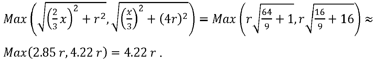
Mit Repellerradien von 0.5m ergibt sich also eine handliche Anlange, die nur wenig mehr Platz benötigt als ein Kreis mit 4m Durchmesser.With repeller radii of 0.5m, this results in a handy system that only requires a little more space than a circle with a diameter of 4m.
Betrachtet man das Verhältnis der gesamten Rotorfläche zum Platzbedarf, so zeigt sich, dass die Nutzung grösserer Repeller günstiger ist. Bei sehr grossen Rotoren und entsprechend grossen Anlangen wird aber die Handhabung zunehmend schwieriger, so dass dem Rotordurchmesser Grenzen gesetzt sind.If you look at the ratio of the total rotor area to the space requirement, it shows that the use of larger repellers is cheaper. With very large rotors and correspondingly large systems, however, handling becomes increasingly difficult, so that the rotor diameter is limited.
Für einen stärkeren Verschattungseffekt, kann der Winkel b grösser gewählt werden als im Beispiel oben. Die Position der Drehachse würde bei 2/3 x bleiben für eine Betriebsrichtung in der die Grundseite auf der windabgewandten Seite liegt. Für eine Betriebsausrichtung in der die Grundseite die windzugewandten Seite darstellt, könnte die Position der Drehachse bei 1/3 x oder etwas davor gewählt werden.For a stronger shading effect, the angle b can be chosen larger than in the example above. The position of the axis of rotation would remain at 2/3 x for an operating direction in which the base side is on the side facing away from the wind. For one Operating orientation in which the base side is the windward side, the position of the axis of rotation could be selected at 1/3 x or slightly in front.
Ein Verfahren zur Konstruktion eine Windturbinenanlage umfassend die Wahl von den folgenden Parametern: Einer Anzahl Repellern und/oder Windhindernissen, die Radien der Repeller und/oder der Windhindernisse, die Verteilung der Repeller und/oder Windhindernisse in mindestens zwei Repellerebenen, die Winkeln zwischen Verbindungslinien von je zwei Repellern und/oder Windhindernisse unterschiedlicher Repellerebenen und einer Symmetrieachse einer Anordnung der Repeller, und dem der Durchstosspunkt der Drehachse auf der Symmetrieachse im Bereich vor dem Belastungsschwerpunkt der Repelleranordnung.A method of constructing a wind turbine system comprising the selection of the following parameters: a number of repellers and / or wind obstacles, the radii of the repellers and / or wind obstacles, the distribution of the repellers and / or wind obstacles in at least two repeller levels, the angles between connecting lines of two repellers and / or wind obstacles of different repeller levels and an axis of symmetry of an arrangement of the repellers, and the point of intersection of the axis of rotation on the axis of symmetry in the area in front of the center of gravity of the repeller arrangement.
All diese Parameter werden so gewählt, dass eine gewünschte Drehmomentfunktion resultiert.All of these parameters are selected so that a desired torque function results.
Die Drehmomentfunktion beschreibt dabei das resultierende Drehmoment bezüglich des Durchstosspunktes der Drehachse in Abhängigkeit des Winkels des Windes zur Symmetrieachse der Repelleranordnung.The torque function describes the resulting torque with respect to the point of intersection of the axis of rotation as a function of the angle of the wind to the axis of symmetry of the repeller arrangement.
Aus der nachfolgenden Detailbeschreibung und der Gesamtheit der Patentansprüche ergeben sich weitere vorteilhafte Ausführungsformen und Merkmalskombinationen der Erfindung.Further advantageous embodiments and combinations of features of the invention result from the following detailed description and the entirety of the claims.
Die zur Erläuterung des Ausführungsbeispiels verwendeten Zeichnungen zeigen:
- Fig. 1
- Eine Skizze zur Bestimmung der Repeller-Kenngrössen.
- Fig. 2
- Eine Skizze zur Erläuterung der verschiedenen Ebenen und Lagebeziehungen.
- Fig. 3a-e
- Verschiedene Beispiele von Repelleranordnungen.
- Fig. 4
- Eine Skizze zur Berechnung des Drehmoments.
- Fig. 5a
- Eine Skizze zur Erläuterung des Begriff "konvexe Hülle".
- Fig.5b
- Eine Skizze zur Erläuterung der Verschattungsfläche.
- Fig. 6a,b
- Eine Skizze zur Erläuterung der möglichen Abweichung der Anordnungsebene von der Senkrechten zu den Repellerebenen.
- Fig. 7a,b
- Skizzen zum Verschattungseffekt für die Fälle "Dreieck im Wind" und "Dreieck gegen den Wind".
- Fig.8a,b
- Nutz- und Brauchfläche für die Fälle "Dreieck im Wind" und "Dreieck gegen den Wind".
- Fig. 9a,b
- Drehmomentfunktion für die Fälle "Dreieck im Wind" und Dreieck gegen den Wind".
- Fig. 10
- Beispiel für eine Windturbinenanordnung.
- Fig. 11a,b
- Ein Beispiel einer Windturbinenanordnung mit Solarpaneelen in der Ansicht von unten und von der Seite .
- Fig. 1
- A sketch for determining the repeller parameters.
- Fig. 2
- A sketch to explain the different levels and relationships.
- 3a-e
- Different examples of repeller arrangements.
- Fig. 4
- A sketch to calculate the torque.
- Fig. 5a
- A sketch to explain the term "convex hull".
- 5 b
- A sketch to explain the shading area.
- 6a, b
- A sketch to explain the possible deviation of the arrangement level from the vertical to the repeller level.
- 7a, b
- Sketches for the shading effect for the cases "triangle in the wind" and "triangle against the wind".
- Figure 8a, b
- Usable and usable space for the "triangle in the wind" and "triangle against the wind" cases.
- 9a, b
- Torque function for the cases "triangle in the wind" and triangle against the wind ".
- Fig. 10
- Example of a wind turbine arrangement.
- 11a, b
- An example of a wind turbine arrangement with solar panels viewed from below and from the side.
Grundsätzlich sind in den Figuren gleiche Teile mit gleichen Bezugszeichen versehen.In principle, the same parts are provided with the same reference symbols in the figures.
Sollte ein Flügel 1.1 mehrere äusserste Punkte 1.11 aufweisen, so kann beispielsweise der am weitesten vorne liegende dieser mehreren Punkte genutzt werden. Der Mittelpunkt 1.2 kann stets als Durchstosspunkt der Rotationsachse durch den Repellerkreis 1.4 definiert werden.If a wing 1.1 has several outermost points 1.11, the most forward of these several points can be used, for example. The center point 1.2 can always be defined as the intersection point of the axis of rotation through the repeller circuit 1.4.
Die gezeigte Windturbinenanlage umfasst drei Repeller 1. Deren Mittelpunkte stellen die Ecken eines Dreiecks dar: Dieses Dreieck ist die Anordnungsfläche 7.1. Die Anordnungsfläche 7.1 liegt in der Anordnungsebene 7. Die Repeller 1 definieren jeweils Repellerkreise 1.4, die wiederum in Repellerbenen 6.1 und 6.2 liegen. Im gezeigten Beispiel liegt ein Repeller 1 in einer vorderen Repellerebene 6.1 und zwei Repeller 1 in einer hinteren Repellerebene 6.2. Die Repellerebenen 6.1 und 6.2 liegen parallel zueinander. Die Lagebeziehung "vorne" und "hinten" ergibt sich auf der Betriebsrichtung. In dem gezeigten Beispiel soll der Wind in der Betriebsrichtung in die mit x bezeichnete Richtung wehen. Die Anordnungsfläche 7.1 weist eine Symmetrieachse 7.2 auf. Die mit x bezeichnete Richtung verläuft entlang der Symmetrieachse 7.2. Eine Drehachse 3.1 durchstösst die Anordnungsfläche 7.1 auf der Symmetrieachse 7.2. Die z-Richtung verläuft parallel zur Drehachse 3.1 und zeigt in die der Lotrichtung entgegengesetzte Richtung. Das genutzte Koordinatensystem soll rechtshändig sein und seinen Ursprung im Mittelpunkt 1.2 des Repellers 1 in der vorderen Repellerebene 6.1 haben.The wind turbine system shown comprises three
Die
![]()
![]()
![]()
![]()
![]()
![]()
![]()
![]()
![]()
![]()
Der Belastungsschwerpunkt 4 ist daher bei ![]()
![]()
Der Durchstosspunkt 3 der Drehachse liegt vor dem Belastungsschwerpunkt 4.The
Durch den Wind 5, der in einem Winkel a zur Symmetrieachse und damit auch zur Betriebsausrichtung weht, wird eine Kraft 4.1 in der gleichen Richtung auf jeden der Repeller und damit auf jeden der Repellermittelpunkte. Diese Kraft kann in ihre x- und y-Komponente aufgeteilt werden: 
Es gibt einen Vektor 3.2, der vom Durchstosspunkt 3 der Drehachse bis zu jedem der Mittelpunkte 1.2 ragt. Der Durchstosspunkt 3 liegt per Wahl des Koordinatensystems auf der x Achse und hat daher die Koordinaten (p,0,0).There is a vector 3.2 which extends from the
Ein beliebiger Mittelpunkt mit Index i liegt in der x-y-Ebene und hat daher die Koordinaten (xi,yi,0).Any center with index i lies in the x-y plane and therefore has the coordinates (xi, yi, 0).
Der Vektor 3.2 vom Durchstosspunkt 3 zum Mittelpunkt 1.2 mit Index i ist also: ![]()

![]()
Das Drehmoment verursacht durch die Kraft Fi (4.1) am Punkt i um die Drehachse, die beim Durchstosspunkt 3 durch die x-y Ebene sticht ist also : 
Wie erwartet, hat ist also nur die z-Komponente von M ungleich 0: ![]()
![]()
Für alle Punkte N gemeinsam summieren sich die Drehmomente auf: 
Auf Grund der Symmetrie muss es Paare i,j geben, bei denen 
![]()
![]()
Um eine Drehung zu erzeugen, die dazu führt, dass die Symmetrieachse der Anordnung den Winkel a mit der x-Achse einschliesst, soll Mz positiv sein.In order to generate a rotation which leads to the symmetry axis of the arrangement including the angle a with the x axis, Mz should be positive.
Das ist der Fall, wenn ![]()
![]()
![]()
![]()
![]()
![]()
Daher entsteht eine gewisse Selbstausrichtung immer dann wenn a) die Symmetrieforderung ( 
Während einzelne Punkte auf der konvexen Hülle liegen, tun viele andere das nicht: Diese liegen in der von der konvexen Hüllen umschlossenen Fläche.While individual points lie on the convex hull, many others do not: these lie in the area enclosed by the convex hull.
D.h.: Wenn D ≥ r 1 + r 2 dann S=0
Ie: If D ≥ r 1 + r 2 then S = 0
Ist der Abstand zwischen den Mittelpunkten 10 (D) kleiner als die Differenz der beiden Radien 1.31 (r1) und 1.32 (r2), dann liegt der kleinere Kreis vollständig im grösseren und die Überlappungsfläche 11 ist gleich des kleineren Kreises:
D.h.: Wenn D ≤ r 1 - r 2 dann ![]()
Ie: If D ≤ r 1 - r 2 then ![]()
Ist der Abstand zwischen den Mittelpunkten 10 (D) zwar grösser als die Differenz der Radien aber kleiner als deren Summe, so überlappen sich die Kreise nur teilweise.If the distance between the center points 10 (D) is greater than the difference of the radii but smaller than their sum, the circles only partially overlap.
Das Dreieck, welches durch die beiden Mittelpunkte und den Schnittpunkt der Kreise aufgespannt wird, hat die Seitenlängen D, r1 und r2. Die Winkel bei den beiden Mittelpunkten lassen sich daher mit dem Kosinussatz berechnen: ![]()
![]()
Die Kreissektoren haben also jeweils eine Fläche von ![]()
![]()
Von dieser Fläche ist nun aber noch die Fläche der Dreiecke abzuziehen, die durch jeweils einen Mittelpunkt und die beiden Schnittpunkte der Kreise aufgespannt werden. Es handelt sich um gleichschenklige Dreiecke mit einem halben Öffnungswinkel von β1 bzw. β2 und einer Schenkellänge von r1 bzw. r2. Da die halbe Grundseite dieser Dreiecks gerade r sin(β) und die Höhe gerade r cos(β) ist und ![]()
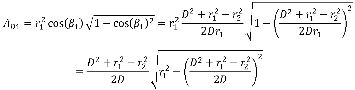

![]()
Insgesamt ist die Überlappungsfläche also ![]()
![]()
Die Anordnungsebene 7 soll im Wesentlichen senkrecht zur Repellerebene stehen. Steht sie nicht genau senkrecht, so soll der Koordinatensystem bevorzugt an der Repellerebene festgemacht werden und nicht an der Anordnungsebene: Im Zweifelsfall ist die x-Achse also senkrecht auf der Repellerebene, auch wenn die Anordnungsebene 7 davon leicht abweicht.The
Die Anordnungsebene soll derart ausgerichtet sein, dass es immer noch zu einem Abschattungseffekt kommt. D.h. bei Wind parallel zur x-y Ebene soll ein vorderer Repeller oder ein vorderes Windhindernis einen hinteren Repeller oder ein hinterliegendes Windhindernis abschatten können.The arrangement level should be aligned in such a way that there is still a shading effect. That in the case of wind parallel to the x-y plane, a front repeller or a front wind obstacle should be able to shade a rear repeller or a rear wind obstacle.
Damit es nun überhaupt zu einem Abschattungseffekt kommen kann, müssen die Radien der Repeller in der vorderen und in der hinteren Repellerebene 6.1 und 6.2 sowie der Abstand 8 (h) der Repellerebenen folgenden Zusammenhang erfüllen: ![]()
![]()
Damit es zu eine signifikanten Überlappung kommt, sollte c aber sehr klein sein, denn der kleinstmögliche Abstand der Mittelpunkte ist Dmin = tan(c) h. So that there is a significant overlap, c should be very small, because the smallest possible distance between the center points is D min = tan ( c ) h.
Zur Illustration nehmen wir an, dass die Radien der Repeller gleich gross sind. Damit ergibt sich die Überlappungsfläche: 

Da D in der vorliegenden Situation nicht kleiner werden kann als Dmin = tan(c) h ist die grösste erreichbare Abschattung: 
Damit mindestens 90% verdeckt werden können, muss ![]()
![]()
Damit mindestens 80% verdeckt werden können, muss ![]()
![]()
Für eine Verdeckung von mehr als 50%, muss ![]()
![]()
![]()
![]()
![]()
![]()
Der Blick des Betrachters geht auf die x-y Ebene. Die Anordnungsfläche ist ein gleichschenkliges Dreieck mit einer Symmetrieachse 7.11. Die Windrichtung 5 in Betriebsausrichtung ist parallel zur Symmetrieachse 7.11. Das gleichschenklige Dreieck der Anordnungsfläche hat einen halben Öffnungswinkel b und einen Höhe h, die gleich dem Abstand der Repellerebenen 8 ist. Die Repeller haben einen Radius r. Wir nehmen hier an, dass die Radien aller Repeller 1 gleich sein.The viewer's gaze goes to the x-y level. The arrangement surface is an isosceles triangle with an axis of symmetry 7.11. The
Der Winkel zwischen Windrichtung und Symmetrieachse 7.11 soll nun zunehmen. Der Winkel zwischen Windrichtung und Symmetrieachse 7.11 wird mit a bezeichnet.The angle between wind direction and axis of symmetry 7.11 should now increase. The angle between wind direction and axis of symmetry 7.11 is denoted by a.
Bei einem Winkel aminC gerät Repeller C in den Windschatten von Repeller A. Bei einem Winkel amaxC ist Repeller C wieder aus dem Windschatten ausgetreten. Bei noch grösseren Winkeln gerät dann Repeller A in den Windschatten von Repeller B. Dies passiert zwischen den Winkeln aminA und amaxA.At an angle a minC, repeller C gets into the slipstream of repeller A. At an angle a maxC , repeller C emerges from the slipstream again. At even larger angles, repeller A then falls into the slipstream of repeller B. This happens between the angles a minA and a maxA .
Die "Grenzwinkel" aminC, amaxC, aminA, amaxA ergeben sich aus folgenden Überlegungen:
- Die halbe Grundseite des Dreiecks ist h*tan(b). Da die Repeller jeweils einen Radius von r haben sollen, ist der Abstand zwischen zwei Repellerkanten in y-Richtung h tan(b)-2r. In x-Richtung ist der Abstand der Repellerkanten gerade h. Also ist

- Die äusseren Repellerkanten haben einen Abstand in y-Richtung von h tan(b)+2r. Der Abstand in x- Richtung ist wiederum h.
Also ist
- Analog ergibt sich aminA = 180° - amaxC und amaxA = 180° - aminC
- Half of the base of the triangle is h * tan (b). Since the repellers should each have a radius of r, the distance between two repeller edges in the y direction is h tan (b) -2r. In the x direction, the distance between the repeller edges is just h. So is
- The outer repeller edges have a distance in the y direction of h tan (b) + 2r. The distance in the x direction is again h.
So is - Similarly, a minA = 180 ° - a maxC and a maxA = 180 ° - a minC
Ersetzt man h = 2rycot(b) so ergeben sich die Winkel: 
In Einheiten der Repellerradien ausgedrückt, ist der Radius 16.1 der in
In der allgemeinsten Form ist das Gesamtdrehmoment folgendes: 
![]()
![]()

![]()
![]()
Auf Grund der Symmetrie wird die Summe über die yi =0 und es folgt der für den Nichtverschatteten Fall bekannte Ausdruck: ![]()
![]()
Die Kraft Fi ist proportional zur Fläche. Bei einer Verschattung fällt die Kraft und entsprechend der Beitrag zum Drehmoment weg. Wenn also ![]()
![]()
![]()
![]()
Für das Drehmoment mit Verschattung ergibt sich so: 
Für den Fall "Dreieck im Wind" ergibt sich folgendes:
Die Repeller sind bei ![]()
![]()
![]()
![]()
![]()
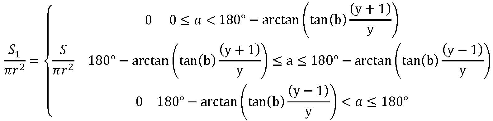
![]()
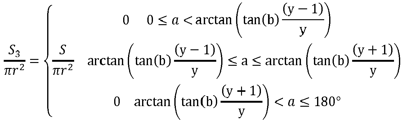
![]()
The repellers are at ![]()
![]()
![]()
![]()
![]()
![]()
![]()
Mit p= 1 /3 h ergibt sich dann für das Drehmoment mit Abschattung folgendes: 
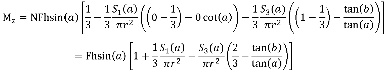
Für den Fall "Dreieck aus dem Wind" ergibt sich folgendes:For the case "triangle from the wind" the following results:
Die Repeller sind bei ![]()
![]()
![]()
![]()
![]()
![]()


![]()
![]()
![]()
![]()
![]()
![]()
![]()
![]()
Für das Drehmoment mit Abschattung ergibt sich folgendes: 
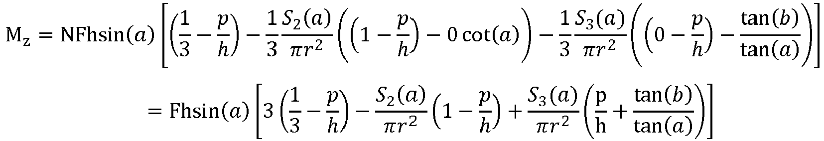
An einer gemeinsamen Drehachse 3.1 sind drei Repeller 1 mit je sechs Flügeln 1.1 zu einer Repelleranordnung 2 gekoppelt. Die Windturbinenanlage umfasst einen weiteren Repeller 12, der nicht zur Repelleranordnung 2 zählt. Ausserdem gibt eine Getriebe- und Generatoreinheit 13, die ebenfalls an die Drehachse 3.1 gekoppelt ist.
Three
Die Windturbinenanlange umfasst 3 Repeller 1. Diese sind jeweils mit ihren Lagern 1.5 an einer Trägerstruktur 15 befestigt. Die Trägerstruktur hat die Form eines "v". Die von den Repellern 1 angetriebenen Achsen 1.6 ragen aus den Lagern 1.5 hinaus und sind untereinander durch Riemen gekoppelt. An der mittleren Achse 1.6 befindet sich eine Generatoreinheit 13. Die Mittelpunkte der Repeller bilden eine Anordnungsfläche 7.1. Diese hat die Form eines gleichschenkligen Dreiecks. Oberhalb der Trägerstruktur 15, der Lager 1.5 und der Achsen 1.6 befinden sich Solarpaneele 14. Die Solarpaneele 14 decken eine in etwa T-förmige Fläche ab. Die Drehachse 3.1 durchsticht die Trägerstruktur 15 und die Solarpaneele 14 im Bereich der Spitze des Vs. Die Anordnungsfläche 7.1 durchsticht die Drehachse 3.1 im Abstand von 2/3 der Höhe des Dreiecks, welches die Anordnungsfläche 7.1 darstellt.The wind turbine plant comprises 3
Zusammenfassend ist festzustellen, dass Repeller der Ausführungsbeispiele auch durch geeignete Windhindernisse ersetzt werden können. Ausserdem können die Geometrien variiert werden: Viele Beispiele beziehen sich auf die Dreieckanordnung, können aber auch mit anders geformten Anordnungsflächen realisiert werden.In summary, it can be stated that repellers of the exemplary embodiments can also be replaced by suitable wind obstacles. In addition, the geometries can be varied: Many examples relate to the triangular arrangement, but can also be realized with differently shaped arrangement surfaces.
Auch kann eine erfindungsgemässe Windturbinenanlange noch mit weiteren, nicht der Repelleranordnung zugehörigen Repellern ausgestattet sein.A wind turbine installation according to the invention can also be equipped with further repellers that do not belong to the repeller arrangement.
Claims (17)
dadurch gekennzeichnet, dass
characterized in that
wobei der Windwinkel gleich dem Winkel zwischen der Verbindungslinie des abschattenden zum abgeschatteten Repeller und der Symmetrieachse ist.Self-aligning wind turbine according to one of claims 1 to 15, wherein the distance between two repeller levels (6.1, 6.2), the radius (1.3) of the largest repeller (1) in the rear level (6.2) by a repeller (1) in the front Plane (6.1) can be shaded and the intersection point of the axis of rotation (3) can be selected such that the ratio of the torque with shading effect to the torque without shading effect is greater than or equal to 1.05 when there is a flow of wind with a wind angle,
where the wind angle is equal to the angle between the line connecting the shadowing to the shaded repeller and the axis of symmetry.
wobei die Drehmomentfunktion ein resultierendes Drehmoment bezüglich des Durchstosspunktes der Drehachse in Abhängigkeit des Winkels des Windes zur Symmetrieachse (7.11) der Repelleranordnung (2) ist.A method of constructing a wind turbine plant according to any one of claims 1 to 16, comprising selecting
the torque function being a resultant torque with respect to the point of intersection of the axis of rotation as a function of the angle of the wind to the axis of symmetry (7.11) of the repeller arrangement (2).
Priority Applications (3)
| Application Number | Priority Date | Filing Date | Title |
|---|---|---|---|
| EP18180452.7A EP3587796A1 (en) | 2018-06-28 | 2018-06-28 | Self-aligning wind turbine installation |
| EP19732695.2A EP3814626B1 (en) | 2018-06-28 | 2019-06-27 | Self-aligning wind turbine installation |
| PCT/EP2019/067212 WO2020002529A1 (en) | 2018-06-28 | 2019-06-27 | Self-aligning wind turbine |
Applications Claiming Priority (1)
| Application Number | Priority Date | Filing Date | Title |
|---|---|---|---|
| EP18180452.7A EP3587796A1 (en) | 2018-06-28 | 2018-06-28 | Self-aligning wind turbine installation |
Publications (1)
| Publication Number | Publication Date |
|---|---|
| EP3587796A1 true EP3587796A1 (en) | 2020-01-01 |
Family
ID=62816398
Family Applications (2)
| Application Number | Title | Priority Date | Filing Date |
|---|---|---|---|
| EP18180452.7A Withdrawn EP3587796A1 (en) | 2018-06-28 | 2018-06-28 | Self-aligning wind turbine installation |
| EP19732695.2A Active EP3814626B1 (en) | 2018-06-28 | 2019-06-27 | Self-aligning wind turbine installation |
Family Applications After (1)
| Application Number | Title | Priority Date | Filing Date |
|---|---|---|---|
| EP19732695.2A Active EP3814626B1 (en) | 2018-06-28 | 2019-06-27 | Self-aligning wind turbine installation |
Country Status (2)
| Country | Link |
|---|---|
| EP (2) | EP3587796A1 (en) |
| WO (1) | WO2020002529A1 (en) |
Citations (7)
| Publication number | Priority date | Publication date | Assignee | Title |
|---|---|---|---|---|
| FR893828A (en) * | 1943-05-12 | 1944-11-02 | Current wind generator unit with differential drive by opposite direction propellers with automatically varying pitch | |
| DE19846796A1 (en) | 1998-10-10 | 2000-04-13 | Dieter Kolbert | Floating wind power system, has electricity generating wind power devices attached to floating system to be as close as possible above sea surface, and symmetrical about floating system center |
| WO2002073032A1 (en) | 2001-03-08 | 2002-09-19 | Ishikawajima-Harima Jukogyo Kabushiki Kaisha | Offshore floating wind power generation plant |
| US6749399B2 (en) | 2002-03-07 | 2004-06-15 | Ocean Wind Energy Systems | Vertical array wind turbine |
| WO2010098813A1 (en) | 2009-02-28 | 2010-09-02 | Ener2 Llc | Wind energy device |
| DE102009040648A1 (en) | 2009-09-09 | 2011-03-10 | Wilhelm Ebrecht | Floatable off shore-wind power plant, has constructional unit arranged at floatable body and comprising poles, at which rotor is supported in rotatable manner, where poles comprise drop-shaped cross sectional contour |
| US20150247486A1 (en) * | 2012-09-10 | 2015-09-03 | Wepfer Technics Ag | Wind turbine |
Family Cites Families (2)
| Publication number | Priority date | Publication date | Assignee | Title |
|---|---|---|---|---|
| WO2011137903A2 (en) * | 2010-05-05 | 2011-11-10 | Stephan Moellgaard Henriksen | Semi-submerged multiple wind-turbine system |
| CN105240221B (en) * | 2014-07-08 | 2019-05-07 | 珠海卡洛斯工程咨询有限公司 | Raft formula box haul water wind power generating device partly latent |
-
2018
- 2018-06-28 EP EP18180452.7A patent/EP3587796A1/en not_active Withdrawn
-
2019
- 2019-06-27 EP EP19732695.2A patent/EP3814626B1/en active Active
- 2019-06-27 WO PCT/EP2019/067212 patent/WO2020002529A1/en active Application Filing
Patent Citations (7)
| Publication number | Priority date | Publication date | Assignee | Title |
|---|---|---|---|---|
| FR893828A (en) * | 1943-05-12 | 1944-11-02 | Current wind generator unit with differential drive by opposite direction propellers with automatically varying pitch | |
| DE19846796A1 (en) | 1998-10-10 | 2000-04-13 | Dieter Kolbert | Floating wind power system, has electricity generating wind power devices attached to floating system to be as close as possible above sea surface, and symmetrical about floating system center |
| WO2002073032A1 (en) | 2001-03-08 | 2002-09-19 | Ishikawajima-Harima Jukogyo Kabushiki Kaisha | Offshore floating wind power generation plant |
| US6749399B2 (en) | 2002-03-07 | 2004-06-15 | Ocean Wind Energy Systems | Vertical array wind turbine |
| WO2010098813A1 (en) | 2009-02-28 | 2010-09-02 | Ener2 Llc | Wind energy device |
| DE102009040648A1 (en) | 2009-09-09 | 2011-03-10 | Wilhelm Ebrecht | Floatable off shore-wind power plant, has constructional unit arranged at floatable body and comprising poles, at which rotor is supported in rotatable manner, where poles comprise drop-shaped cross sectional contour |
| US20150247486A1 (en) * | 2012-09-10 | 2015-09-03 | Wepfer Technics Ag | Wind turbine |
Also Published As
| Publication number | Publication date |
|---|---|
| WO2020002529A1 (en) | 2020-01-02 |
| EP3814626A1 (en) | 2021-05-05 |
| EP3814626B1 (en) | 2023-11-29 |
| EP3814626C0 (en) | 2023-11-29 |
Similar Documents
| Publication | Publication Date | Title |
|---|---|---|
| DE102006021182B4 (en) | Aircraft with four lifting rotors and three axes of rotation as a universal flight platform | |
| DE102005046155B4 (en) | Helicopters with coaxial main rotors | |
| EP1979611B1 (en) | Rotating device to be used in a fluid | |
| DE2602380A1 (en) | ROTATING DEVICE PROVIDED BY A MOVING FLUID SUCH AS WATER OR AIR POWERED | |
| DE2604005A1 (en) | DEVICE FOR INFLUENCING THE POSITION AND LOCATION OF A SATELLITE | |
| CH700332B1 (en) | Wind Turbine. | |
| DE102011052668A1 (en) | Hub for a wind turbine and method for assembling a wind turbine | |
| DE3119736A1 (en) | WIND TURBINE | |
| EP2075461B1 (en) | Method and system for conversion of kinetic energy contained in horizontal flows into usable mechanical energy | |
| DE2814813A1 (en) | WIND POWER MACHINE | |
| EP3814626B1 (en) | Self-aligning wind turbine installation | |
| DE102018114004A1 (en) | Wind turbine with vertical axis of rotation of the rotor and floating wind farm with several such wind turbines | |
| DE2318788C2 (en) | High speed watercraft | |
| DE102017126691A1 (en) | Wind turbine | |
| EP4189235A1 (en) | Universal propeller, operating method and favoured uses | |
| DE202010016041U1 (en) | Wind turbine and wind farm | |
| DE3810339A1 (en) | WIND TURBINE | |
| DE19932004B4 (en) | Wave power station | |
| DE3713024A1 (en) | Turbine for obtaining energy | |
| DE102013226174A1 (en) | Rotor for a wind turbine | |
| DE102009008805A1 (en) | Wind turbine for use in generation of power, has vane whose surface is formed such that counter torque is less around vertical yaw axis by wind effect on vane and lesser than torque around yaw axis by wind effect on wind wheel | |
| DE102016110204A1 (en) | Wind turbine and wind turbine | |
| DE102010026706A1 (en) | Fastening device for securing Flettner rotor at tensioned endless rope of e.g. wind power plant, utilized for generating electricity, has lateral axle lying in plane that divides rotar longitudinal axis, which lies in two bend points | |
| DE2816382C2 (en) | ||
| DE573958C (en) | Arrangement of propellers on a gas-filled aircraft |
Legal Events
| Date | Code | Title | Description |
|---|---|---|---|
| PUAI | Public reference made under article 153(3) epc to a published international application that has entered the european phase |
Free format text: ORIGINAL CODE: 0009012 |
|
| STAA | Information on the status of an ep patent application or granted ep patent |
Free format text: STATUS: THE APPLICATION HAS BEEN PUBLISHED |
|
| AK | Designated contracting states |
Kind code of ref document: A1 Designated state(s): AL AT BE BG CH CY CZ DE DK EE ES FI FR GB GR HR HU IE IS IT LI LT LU LV MC MK MT NL NO PL PT RO RS SE SI SK SM TR |
|
| AX | Request for extension of the european patent |
Extension state: BA ME |
|
| STAA | Information on the status of an ep patent application or granted ep patent |
Free format text: STATUS: THE APPLICATION IS DEEMED TO BE WITHDRAWN |
|
| 18D | Application deemed to be withdrawn |
Effective date: 20200702 |