EP4091939A1 - Aéronef - Google Patents
Aéronef Download PDFInfo
- Publication number
- EP4091939A1 EP4091939A1 EP21175290.2A EP21175290A EP4091939A1 EP 4091939 A1 EP4091939 A1 EP 4091939A1 EP 21175290 A EP21175290 A EP 21175290A EP 4091939 A1 EP4091939 A1 EP 4091939A1
- Authority
- EP
- European Patent Office
- Prior art keywords
- aircraft
- rotation
- drive devices
- devices
- straight line
- Prior art date
- Legal status (The legal status is an assumption and is not a legal conclusion. Google has not performed a legal analysis and makes no representation as to the accuracy of the status listed.)
- Pending
Links
- 239000013598 vector Substances 0.000 claims abstract description 228
- 230000005484 gravity Effects 0.000 claims description 26
- 238000000034 method Methods 0.000 claims description 22
- 230000000284 resting effect Effects 0.000 claims description 7
- 238000004519 manufacturing process Methods 0.000 claims description 6
- 238000006073 displacement reaction Methods 0.000 claims description 4
- 239000000446 fuel Substances 0.000 claims description 4
- 239000002828 fuel tank Substances 0.000 claims description 4
- 230000000694 effects Effects 0.000 description 31
- 230000008878 coupling Effects 0.000 description 23
- 238000010168 coupling process Methods 0.000 description 23
- 238000005859 coupling reaction Methods 0.000 description 23
- 230000033001 locomotion Effects 0.000 description 18
- 230000007246 mechanism Effects 0.000 description 15
- 230000008859 change Effects 0.000 description 10
- 230000000737 periodic effect Effects 0.000 description 7
- 230000008092 positive effect Effects 0.000 description 7
- 230000008901 benefit Effects 0.000 description 5
- 210000002023 somite Anatomy 0.000 description 4
- 208000012886 Vertigo Diseases 0.000 description 3
- 208000031872 Body Remains Diseases 0.000 description 2
- 230000001133 acceleration Effects 0.000 description 2
- 238000004364 calculation method Methods 0.000 description 2
- 230000001419 dependent effect Effects 0.000 description 2
- 238000009795 derivation Methods 0.000 description 2
- 238000011161 development Methods 0.000 description 2
- 230000018109 developmental process Effects 0.000 description 2
- 230000014509 gene expression Effects 0.000 description 2
- 101100189913 Caenorhabditis elegans pept-1 gene Proteins 0.000 description 1
- 230000002349 favourable effect Effects 0.000 description 1
- 238000012886 linear function Methods 0.000 description 1
- 238000003032 molecular docking Methods 0.000 description 1
- 238000005457 optimization Methods 0.000 description 1
- 230000008569 process Effects 0.000 description 1
- 230000009467 reduction Effects 0.000 description 1
- 238000003860 storage Methods 0.000 description 1
- 239000000725 suspension Substances 0.000 description 1
Images


Classifications
-
- B—PERFORMING OPERATIONS; TRANSPORTING
- B64—AIRCRAFT; AVIATION; COSMONAUTICS
- B64C—AEROPLANES; HELICOPTERS
- B64C29/00—Aircraft capable of landing or taking-off vertically, e.g. vertical take-off and landing [VTOL] aircraft
- B64C29/0008—Aircraft capable of landing or taking-off vertically, e.g. vertical take-off and landing [VTOL] aircraft having its flight directional axis horizontal when grounded
- B64C29/0016—Aircraft capable of landing or taking-off vertically, e.g. vertical take-off and landing [VTOL] aircraft having its flight directional axis horizontal when grounded the lift during taking-off being created by free or ducted propellers or by blowers
- B64C29/0025—Aircraft capable of landing or taking-off vertically, e.g. vertical take-off and landing [VTOL] aircraft having its flight directional axis horizontal when grounded the lift during taking-off being created by free or ducted propellers or by blowers the propellers being fixed relative to the fuselage
-
- B—PERFORMING OPERATIONS; TRANSPORTING
- B64—AIRCRAFT; AVIATION; COSMONAUTICS
- B64C—AEROPLANES; HELICOPTERS
- B64C29/00—Aircraft capable of landing or taking-off vertically, e.g. vertical take-off and landing [VTOL] aircraft
- B64C29/0008—Aircraft capable of landing or taking-off vertically, e.g. vertical take-off and landing [VTOL] aircraft having its flight directional axis horizontal when grounded
- B64C29/0016—Aircraft capable of landing or taking-off vertically, e.g. vertical take-off and landing [VTOL] aircraft having its flight directional axis horizontal when grounded the lift during taking-off being created by free or ducted propellers or by blowers
- B64C29/0033—Aircraft capable of landing or taking-off vertically, e.g. vertical take-off and landing [VTOL] aircraft having its flight directional axis horizontal when grounded the lift during taking-off being created by free or ducted propellers or by blowers the propellers being tiltable relative to the fuselage
-
- B—PERFORMING OPERATIONS; TRANSPORTING
- B64—AIRCRAFT; AVIATION; COSMONAUTICS
- B64U—UNMANNED AERIAL VEHICLES [UAV]; EQUIPMENT THEREFOR
- B64U10/00—Type of UAV
- B64U10/20—Vertical take-off and landing [VTOL] aircraft
-
- B—PERFORMING OPERATIONS; TRANSPORTING
- B64—AIRCRAFT; AVIATION; COSMONAUTICS
- B64U—UNMANNED AERIAL VEHICLES [UAV]; EQUIPMENT THEREFOR
- B64U30/00—Means for producing lift; Empennages; Arrangements thereof
- B64U30/20—Rotors; Rotor supports
Definitions
- the invention relates to an aircraft and a method for manufacturing and controlling the aircraft.
- the invention relates to an aircraft that can assume a stable hovering flight with drive devices rotating in the same direction, in particular cyclogyro rotors.
- cyclogyros Aircraft that use cyclogyro rotors as propulsion devices are called cyclogyros.
- cyclogyros are, just like helicopters, so-called vertical take-off vehicles (also called VTOL vehicles, from English "Vertical Take-Off and Landing”), i.e. aircraft that are able to take off vertically without a take-off and runway to take off and land.
- vertical take-off vehicles also called VTOL vehicles, from English "Vertical Take-Off and Landing”
- a cyclogyro rotor is based on the principle of generating thrust with rotating wings, which are then called rotor blades.
- the axis of rotation of the blades of a cyclogyro rotor is aligned parallel to the longitudinal axis of the wings / rotor blades.
- the direction of thrust of the entire cyclogyro rotor is normal to the axis of rotation.
- all rotor blades of the cyclogyro rotor should ideally be aligned with the direction of flow as best as possible at all times in order to make a maximum contribution to the total thrust with the minimum required drive power.
- the maximum inclination of the rotor blades in relation to the flow direction directly influences the amount of thrust generated.
- the pitch of each blade must change continuously during one revolution.
- Each rotor blade of a cyclogyro rotor thus undergoes a periodic change in angle of inclination. This periodic change in pitch angle is called pitch motion.
- each rotor blade can be connected to an eccentric bearing axle via one or more connecting rods.
- the resulting pitch movement of a rotor blade is repeated cyclically with each rotor revolution.
- a thrust vector is generated normal to the axis of rotation of the rotor.
- the periodic rotor blade adjustment is changed, and thus the thrust vector can be rotated in the entire plane that is normal to the axis of rotation of the rotor (thrust vector control).
- the rotor In addition to the thrust vector, the rotor generates a torque about the axis of rotation counter to the direction of rotation of the rotor resulting from the tangential components of the air forces acting on the rotor blades, namely the lift and air resistance forces.
- the direction of the transverse force depends on the turning direction of the body or here: the cyclogyro rotor.
- the object of the present invention is therefore to provide an aircraft that is able to assume a stable flight attitude even at high speeds in forward flight.
- an aircraft comprising the following components: an aircraft body defining a longitudinal direction, a vertical direction and a transverse direction, the longitudinal direction corresponding to the direction from the tail to the nose of the aircraft, the vertical direction corresponding to the direction of gravity coincides when the aircraft is resting on the ground and the lateral direction is perpendicular to the longitudinal direction and the vertical direction, and at least two drive devices which are rotatable about a respective associated axis of rotation in order to generate a respective associated thrust vector.
- a first number of drive devices is arranged along a first straight line that runs parallel to the transverse direction
- a second number of drive devices is arranged along a second straight line that runs parallel to the transverse direction.
- the first straight line is spaced from the second straight line, and the center of mass of the aircraft is positioned longitudinally between the first straight line and the second straight line.
- the aircraft is designed to perform a hover flight, in which all on the aircraft acting forces and all torques acting on the aircraft in relation to the center of mass of the aircraft essentially disappear, in that each of the assigned axes of rotation is aligned essentially in the transverse direction of the aircraft body in hovering flight, and each of the at least two drive devices essentially in the same direction of rotation around the respectively assigned one axis of rotation rotates.
- an axis of rotation is aligned essentially in the transverse direction of the aircraft body if the angle enclosed between the axis of rotation and an axis that runs in the transverse direction and intersects the axis of rotation is less than 45°, preferably less than 30°, particularly preferably less than 15°.
- the drive devices rotate essentially in the same direction of rotation if the scalar product of the vector of the angular velocity of a specific drive device and a fixed, predetermined, but arbitrary vector pointing in the transverse direction has the same sign for all drive devices. That is to say, in order to check that all of the drive devices under consideration or each of the drive devices under consideration essentially rotate in the same direction of rotation, a vector in the transverse direction is first specified in a fixed manner. Then, for a first drive device, the scalar product of its angular velocity vector and the fixedly specified vector is calculated; thereafter, for a second drive device, the scalar product of its angular velocity vector and the fixed vector; etc.
- the aircraft Due to the fact that the aircraft is designed in such a way that it hovers with drive devices rotating essentially in the same direction, a reduction in the power consumption of the drive devices is achieved. To put it simply, the Magnus effect occurring according to the invention replaces part of the thrust of the drive devices and thus reduces the power requirement in forward flight compared to hovering flight. Because more residual power remains for the drive devices in forward flight, the agility of the aircraft in forward flight in particular increases.
- the Magnus effect states that a rotating round body in a flow experiences a transverse force normal to the flow direction.
- an additional thrust vector or an additional thrust force in the vertical direction can be generated by this effect.
- the Magnus effect replaces part of the thrust force to be applied by the propulsion device and thus reduces the power requirement in forward flight compared to hovering flight. If the rotor is now in forward flight, it is actively flown with air from the front.
- the additional transverse force of the Magnus effect acts essentially in the same direction as the thrust of the drive devices with constant flow, and thus increases the total thrust or reduces the power requirement with the same required buoyancy.
- the positive effect of the Magnus effect requires lower power and/or rotational speed of the drive devices in order to keep the aircraft in a stable flight attitude.
- the aircraft is further designed so that in hovering flight the center of mass of the aircraft is positioned in such a way that this causes all forces acting on the aircraft and all torques acting on the aircraft with respect to the center of mass of the aircraft to be Essentially disappear when one or more of the propulsion devices generate a specific predetermined thrust vector assigned to them.
- the longitudinal center of mass of the aircraft must be within a range determined by the aircraft's ability to hover when one or more of the propulsion devices are powered at maximum thrust or maximum thrust vector . In other words, when the center of mass is within said range, the propulsion devices are able to generate appropriate thrust vectors to allow the aircraft to hover.
- the flow velocity is generally lower than in forward flight. Because the thrust vectors of the drive devices for hovering are specified for the aircraft according to the invention, and the position of the center of mass is determined for hovering, it is ensured that a stable flight attitude is also possible in forward flight. As explained above, the positive effect according to the invention, which is brought about by the Magnus effect, is greater the greater the inflow speed. Therefore, the inventive configuration of the aircraft in hovering ensures that the aircraft can assume a stable flight attitude, especially in forward flight, because in forward flight the Magnus effect leads to a greater increase in the thrust vector than in the case of hovering.
- the thrust force or the thrust vector is used to generate the required lift force and/or to regulate the flight attitude of the aircraft.
- the aircraft expediently comprises a thrust vector control, which regulates the required thrust force or required thrust vectors in hovering flight and/or in forward flight.
- Each of the drive devices according to the invention generates a torque counter to the direction of rotation.
- This torque about the axis of rotation counter to the direction of rotation of the drive device results from tangential air forces caused, among other things, by air resistance.
- the drive device In order to maintain a constant speed of rotation, the drive device must thus produce a (drive) torque that is due to the counteracts the torque resulting from tangential air forces.
- this latter torque (ignoring dissipative effects) is approximately equal in magnitude to the torque generated by the tangential aerodynamic forces, and also points in the same direction as the latter. Since the torque generated by the air forces counteracts the direction of rotation of the drive device, the torque applied by the aircraft body also counteracts the direction of rotation of the drive device. Assuming that the torque due to the air forces and that of the propulsion device are essentially the same in terms of magnitude but directed in opposite directions, the torque applied by the aircraft body remains as the net torque due to the rotation of the propulsion device.
- This torque or these torques are compensated according to the invention in that the center of mass of the aircraft is positioned in such a way that, taking into account the thrust vectors assigned and specified to the drive devices, all forces acting on the aircraft in hovering flight and all forces related to the center of mass of the aircraft on the aircraft applied torques essentially disappear.
- the acceleration vector r ⁇ s and the change in the angular momentum vector L ⁇ s over time must be zero.
- both the sum of all external forces ( F ) and the sum of all torques around the center of mass ( M s ) must result in zero.
- the forces acting on the aircraft in hover are gravity and the thrust of the propulsion devices.
- the torques acting with respect to the center of mass of the aircraft are the torques generated by the thrust vectors of the propulsion devices mounted at appropriate distances from the center of mass of the aircraft, and the (supporting) torques generated by the aircraft body, and all point in substantially the same direction.
- the balance of forces and torques can thus be achieved by selecting the thrust forces or thrust vectors of the drive devices and their distances from the center of mass of the aircraft accordingly.
- the first number of drive devices is preferably arranged in a front area of the aircraft with respect to the longitudinal direction, and the second number of drive devices is arranged in a rear area of the aircraft with respect to the longitudinal direction.
- the aircraft preferably comprises three drive devices.
- the aircraft particularly preferably comprises four drive devices, with two of the drive devices being arranged in a front area of the aircraft in relation to the longitudinal direction, and two further drive devices being arranged in relation to the Are arranged longitudinally in a rear area of the aircraft.
- the overall length of the aircraft is measured longitudinally.
- the relative longitudinal coordinate 0 is assigned to the frontmost part of the aircraft and the relative longitudinal coordinate 100% to the rearmost part of the aircraft.
- the front area is defined as corresponding to the (longitudinal) area from 0 to 40% of the overall length of the aircraft
- the rear area as corresponding to the (longitudinal) area from 60% to 100% of the overall length of the aircraft Aircraft corresponds. It is also expedient if the two drive devices arranged in the front area lie on a common straight line which is aligned parallel to the transverse direction. It is also expedient if the two drive devices arranged in the rear area lie on a common straight line which is aligned parallel to the transverse direction.
- the aircraft is also expediently designed so that the assigned axes of rotation are aligned in parallel when hovering.
- the aircraft in addition to the at least two drive devices contributing to the effect according to the invention, also comprises further drive devices which do not essentially rotate in the same direction of rotation.
- an aircraft which comprises an aircraft fuselage and at least three propulsion devices which are mounted around the aircraft fuselage and which can be rotated about a respective associated axis of rotation in order to generate a respective associated thrust vector.
- the aircraft is designed to hover in which all forces acting on the aircraft and all torques acting on the aircraft with respect to the center of mass of the aircraft essentially disappear, in that during hovering the associated axes of rotation of two of the at least three drive devices essentially are oriented in a first direction, and the associated axis of rotation of another of the at least three propulsion devices is substantially oriented in the second direction, the first direction being non-parallel to the second direction, and each of the two propulsion devices being oriented in the first direction when in hover Axis of rotation rotates substantially in the same direction of rotation about the respective associated axis of rotation.
- the first direction is not parallel to the second direction if a (reference) axis pointing in the first direction is not parallel to a (reference) axis pointing in the second direction.
- the angle between the first and second directions is preferably in the range from 30° to 110°, preferably in the range from 40° to 100°, particularly preferably in the range from 60° to 95°.
- the at least three drive devices are preferably mounted essentially in one plane around the aircraft fuselage.
- the aircraft fuselage is expediently in the plane, i.e. the plane intersects the aircraft fuselage. It is also advantageous if the first direction and the second direction lie in the same plane.
- “supported essentially in one plane” means that the drive devices or their mounting points do not have to be contained in one plane in exactly the same way. It is also still according to the invention if one or more of the drive devices are pivoted out of the plane and/or the drive devices are offset vertically with respect to the plane.
- the vertical offset is expediently limited by the vertical extent of the aircraft fuselage, i.e. the propulsion devices are suitably mounted in such a way that the axes of rotation of the propulsion devices are contained in the space formed between two horizontal planes which touch the aircraft fuselage and around the vertical extent of the aircraft fuselage are spaced apart.
- the vertical extent is related to the direction of gravity when the aircraft is resting on the (level) ground.
- Each of the axes of rotation of the two of the at least three drive devices, which are essentially aligned in the first direction, is preferably aligned in such a way that it is essentially parallel to a straight line which runs through the two drive devices. It is expedient if the straight line is placed through the geometric centers (the term is explained below) or bearing points of the drive devices.
- an axis of rotation is essentially parallel to a straight line if the angle enclosed between the axis of rotation and the straight line is less than 45°, preferably less than 30°, particularly preferably less than 15°.
- the aircraft particularly preferably comprises at least four drive devices which are mounted around the aircraft fuselage and which can be rotated about a respective assigned axis of rotation in order to generate a respective assigned thrust vector.
- the aircraft is designed to carry out the hovering flight in that during the hovering flight the assigned axes of rotation of two of the at least four drive devices essentially point in the first direction are aligned, and the assigned axes of rotation of two further of the at least four drive devices are essentially aligned in the second direction, wherein each of the two drive devices with axes of rotation aligned in the first direction when hovering rotates essentially in the same direction of rotation about the respective assigned axis of rotation, and /or each of the two drive devices rotates in hovering flight with the axes of rotation aligned in the second direction essentially in the same direction about the respective associated axis of rotation.
- the Magnus effect in forward flight therefore has the strongest effect on those drive devices whose axes of rotation are aligned essentially perpendicular to the direction of flight, due to the essentially identical rotational rotation. That is, with the arrangement of the drive devices according to the second aspect of the invention, it is sufficient if the aircraft is configured in such a way that, in hovering flight, each of the two drive devices with axes of rotation aligned in the first direction in hovering flight essentially in the same direction of rotation about the respectively assigned Axis of rotation rotates, or, in the case of at least four drive devices, each of the two drive devices rotates in hovering aligned in the second direction axes of rotation substantially in the same direction of rotation about the respective associated axis of rotation.
- the two driving devices that do not rotate in substantially the same direction rotate in opposite directions. If these two drive devices rotate in opposite directions, the torque cancels out directly.
- the aircraft if it comprises at least four drive devices, to be configured in such a way that, in hovering flight, each of the two drive devices has its axes of rotation aligned in the first direction in hovering flight rotates substantially in the same direction of rotation about the respectively assigned axis of rotation, and each of the two drive devices rotates substantially in the same direction of rotation about the respectively assigned axis of rotation with axes of rotation aligned in the second direction in hovering flight. It can thus be ensured that the aircraft can utilize the positive effect of the Magnus effect when flying forward both in the first direction and in the second direction. The aircraft is thus more flexible and stable when changing flight direction.
- the aircraft is further designed so that the center of mass of the aircraft is positioned in hovering flight in such a way that all forces acting on the aircraft and all torques acting on the aircraft with respect to the center of mass of the aircraft essentially disappear when one or several of the propulsion devices generate a specific predetermined thrust vector assigned to them.
- the center of mass of the aircraft must be within a range determined by the aircraft's ability to hover when one or more of the propulsion devices are powered at maximum thrust or maximum thrust vector. In other words, when the center of mass is within said range, the propulsion devices are able to generate appropriate thrust vectors to allow the aircraft to hover.
- each of the axes of rotation of the two of the at least four drive devices is aligned in such a way that it runs essentially parallel to a straight line that runs through the two drive devices. It is also preferred if each of the axes of rotation, which are essentially aligned in the second direction, of the two further of the at least four drive devices is aligned in such a way that it runs essentially parallel to a straight line which runs through these two further drive devices. It is expedient if the straight lines are laid through the geometric centers or bearing points of the drive devices.
- the compensation is made for the drive device(s) generated by the drive devices rotating essentially in the same direction Torques or torques according to the invention in that the center of mass of the aircraft is positioned in such a way that, taking into account the thrust vectors assigned to the drive devices and specified in each case, all forces acting on the aircraft and all torques acting on the aircraft with regard to the center of mass of the aircraft essentially disappear.
- the balance of all forces and torques acting on the aircraft must be met. The calculation is carried out using the law of momentum and twist, which have already been specified and described in connection with the first aspect of the invention. The statements made there apply accordingly here, and this is explained further below.
- three drive devices are arranged around the aircraft fuselage in such a way that they form the corners of a triangle, preferably an equilateral triangle.
- the aircraft fuselage is expediently located in the geometric center of the triangle.
- the first direction is defined by a straight line on which two of the three drive devices lie; the second direction is substantially perpendicular to the first direction.
- the axis of rotation of each of the two drive devices lying on the straight line pointing in the first direction encloses an angle with said straight line which is in the range between 0° and 45°, expediently between 0° and 30°.
- the geometric center corresponds to the mean of all points within the triangle (i.e. the mean over the area of the triangle with constant density).
- the angle between the axis(s) of rotation and the straight line pointing in the first direction is chosen to be 30°, then the axis(s) of rotation of the drive devices point(s) towards (or away from) the geometric center.
- the angle can also be selected differently for each of the drive devices. It is expedient if the straight line is laid through the geometric centers or bearing points of the drive devices.
- n drive devices are arranged around the aircraft fuselage in such a way that they form the corners of an n -gon, n >3, expediently the corners of a regular n -gon, n >3.
- the aircraft fuselage is expediently located in the geometric center of the n -gon.
- the first direction is defined by a first straight line on which two of the n drive devices lie; the second direction is through defines a second straight line on which two more of the n drive devices lie.
- the axis of rotation of each of the two drive devices lying on the first straight line pointing in the first direction encloses an angle with the first straight line which is in the range between 0° and 45°, expediently between 0° and 30°, expediently in the range between 0° and 20°, particularly preferably in the range between 0° and 18°.
- the axes of rotation of different drive devices can enclose different angles with the first straight line.
- the axis of rotation of each of the two drive devices lying on the second straight line pointing in the second direction encloses an angle with the second straight line which is in the range between 0° and 45°, expediently between 0° and 30° is in the range between 0° and 20°, particularly preferably in the range between 0° and 18°.
- the axes of rotation of different drive devices can enclose different angles with the second straight line.
- angles are selected as mentioned above, it is possible for the axes of rotation of the drive devices to point in the direction of the geometric center of the n -gon (or away from it).
- the aircraft comprises 3, 4, 5, 6, 7, 8, ... drive devices which are arranged around the aircraft fuselage in such a way that they form the corners of an equilateral triangle, a square, a regular 5-, 6-, 7-corners, or regular 8-corners, etc.
- the fuselage of the aircraft is expediently positioned essentially in the center of the n -gon, the geometric center, but not the center of mass, of the n -gon being used here; because, according to the invention, the center of mass of the aircraft does not necessarily have to coincide with the geometric center (geometric center of gravity).
- the geometric center of an n -gon is defined according to the geometric center of the triangle.
- n 2j, j >1.
- the aircraft fuselage it is also expedient for the aircraft fuselage to be located between two opposing drive devices of the regular 2j -corner.
- the axes of rotation associated with two specific opposing drive devices are each essentially in the direction which is defined by a straight line on which the two specific opposite drive devices lie.
- the aircraft is designed to carry out the hover flight by rotating two opposite drive devices essentially in the same direction about the axis of rotation assigned to them during the hover flight. In this case, j directions according to the invention can then be defined.
- the angle between the first straight line and the second straight line is advantageously in the range between 60° and 100°, preferably between 60° and 90°, particularly preferably between 70° and 90°, particularly preferably between 72° and 90°.
- j > 1 it is particularly advantageous to choose the first straight line and the second straight line (or corresponding directions) in such a way that the angle between the first straight line and second straight line is 90° ⁇ (1 - 1/(2 j + 1)).
- a particularly preferred range for the angle between the first and second straight line is given by: [90°*(1 ⁇ 1/( 2j +1)); 90 degrees].
- angles between the axes of rotation of the drive devices arranged along the first straight line and the first straight line are in the range [0°; 90°/( 2j +1)], and/or the angles between the axes of rotation of the drive devices arranged along the second straight line and the second straight line in the range [0°; 90°/(2 j + 1)]
- configurations can be implemented in which the axes of rotation of the drive devices point in the direction of (or away from) the geometric center of the (2 j + 1) corner.
- first straight line and the second straight line in such a way that they enclose an angle that is 90° - 90°/(2 j ) (2 j mod 4) is. Then the first and the second straight line each run through the geometric center of the 2 j -gon.
- a particularly preferred range for the angle between the first and second straight line is therefore given by: [90° - 90°/ j ; 90 degrees].
- first straight line and the second straight line are determined so that the angle between them is in the range [60°; 90°], and the angles between the axes of rotation of the drive devices arranged along the first straight line and the first straight line are in the range [0°; 30°], and/or the angles between the axes of rotation of the drive devices arranged along the second straight line and the second straight line in the range [0°; 30°], can the drive devices are arranged in an (arbitrary) regular n -gon ( n > 2) around the aircraft fuselage, so that the axes of rotation of the drive devices are aligned in the direction of (or away from) the geometric center. If n > 3 is to be considered, it is sufficient if the angle between the axis of rotation of a drive device and the first or second straight line running through it is in the range [0°; 18°].
- the second direction is expediently essentially perpendicular, particularly preferably perpendicular, to the first direction, and two of the at least four drive devices are arranged along the first direction, and the other two of the at least four drive devices are along the essentially perpendicular to the first direction arranged second direction.
- the propulsion devices may be located around the aircraft fuselage at the corners of a square.
- each of the aircraft of the first or second aspect if it also has a displacement device with which the center of gravity of the aircraft can be displaced.
- the aircraft also expediently comprises a fuel tank for supplying the drive devices with fuel and/or a battery for supplying the drive devices with electrical energy, with the displacement device being designed to displace fuel from the fuel tank or the battery within the aircraft in order to use it to To position the center of mass so that the aircraft performs the hover flight when one or more of the propulsion devices generate the respectively assigned specific predetermined thrust vector.
- the center of mass of the aircraft can therefore be dynamically shifted.
- the advantage is that the center of mass of the aircraft can be adjusted to various flight attitudes can be optimally adjusted accordingly.
- the center of mass can be shifted by an aircraft control system.
- the aircraft preferably comprise a thrust vector control in order to control the thrust vectors of the propulsion devices individually.
- the aircraft comprises at least four drive devices
- the assigned axes of rotation of two of the at least four drive devices are essentially aligned in the first direction
- the assigned axes of rotation of two more of the at least four drive devices are essentially aligned in the second direction
- each of the two propulsion devices with axes of rotation aligned in the first direction in hovering flight rotates essentially in the same direction of rotation about the respective associated axis of rotation
- each of the two propulsion devices with axes of rotation aligned in the second direction in hovering flight rotates in essentially the same direction of rotation the associated axis of rotation.
- all of the specific associated thrust vectors are preferably chosen to be approximately identical.
- each of the drive devices is preferably embodied in a structurally identical manner.
- the propulsion devices comprise cyclogyro rotors.
- each cyclogyro rotor expediently comprises a plurality of rotor blades which can be rotated along a circular path about the respectively assigned axis of rotation of the drive device or of the cyclogyro rotor; a pitch mechanism with a coupling device and a bearing device, each of the plurality of rotor blades being pivotably mounted by the bearing device about its rotor blade bearing axis parallel to the axis of rotation of the drive device or the cyclogyro rotor.
- the cyclogyro rotor expediently comprises an offset device to which each rotor blade is coupled by the coupling device at a connection point assigned to it.
- the offset device defines an eccentric bearing axis, which is mounted parallel to the axis of rotation of the drive device or the cyclogyro rotor at an adjustable offset distance.
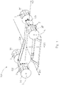
- figure 1 shows a perspective view of an aircraft 100 according to the first aspect of the invention with an aircraft body 120 and a plurality of drive devices 1F, 1R. Every of the drive devices 1F, 1R can be mounted on the aircraft body 120 with appropriate mounting or bearing devices.
- the aircraft 100 shown can be, for example, an aircraft, a manned aircraft, a drone or what are known as micro air vehicles (MAVs).
- MAVs micro air vehicles
- a coordinate system is introduced which defines a longitudinal direction 101 or longitudinal axis, a transverse direction 102 or transverse axis and a vertical direction 103 or vertical axis.
- the coordinate system should be firmly anchored to the aircraft 100.
- the reference directions 101, 102, 103 or axes are defined as follows:
- the longitudinal direction 101 corresponds to the direction from the tail 122 to the nose 121 of the aircraft 100.
- the longitudinal direction 101 thus lies in a horizontal plane (parallel to the ground when the aircraft 100 is resting on the ground), and extends from the tail 122 (i.e.
- the vertical direction 103 or axis corresponds to the direction of gravity when the aircraft 100 rests on the (level) ground.
- the vertical direction 103 is perpendicular to the aforementioned horizontal plane, which includes the longitudinal direction 101 .
- the transverse direction 102 or axis is perpendicular both to the longitudinal direction 101 and to the vertical direction 103.
- the transverse direction 102 lies in the aforementioned horizontal plane, which includes the longitudinal direction 101, and is perpendicular to the longitudinal direction 101.
- the aircraft 100 shown has four drive devices 1F, 1R.
- the drive devices 1F, 1R shown are cyclogyro rotors. This in 1
- the aircraft 100 shown can therefore also be referred to as a cyclogyro.
- the drive devices are associated with figure 5 described in more detail.
- Each of these drive devices 1F, 1R is rotatably mounted about an axis of rotation 5 assigned to it.
- Each drive device 1F, 1R includes a plurality of rotor blades 2, which are pivotably mounted about their longitudinal axis.
- the angle of inclination of the rotor blades 2 can thus be varied during the rotation of the drive device 1F, 1R.
- rotation speed hereinafter also referred to as rotation speed
- the two of the four propulsion devices 1F are arranged in the front (nose) area of the aircraft 100
- two other propulsion devices 1R are arranged in the rear (tail) area of the aircraft 100.
- the front and rear areas of the aircraft are defined as follows: The overall length of the aircraft is measured in longitudinal direction 101; the foremost part of the aircraft (ie the nose 121 of the aircraft 100) is assigned the relative longitudinal coordinate 0, and the rearmost part 122 of the aircraft 100 is assigned the relative longitudinal coordinate 100%.
- the front portion or area is defined as corresponding to the 0 to 40% (longitudinal) range of the overall length of the aircraft, the rear portion or area as corresponding to the 60% (longitudinal) range up to 100% of the total length of the aircraft.
- the two drive devices 1F in the front area lie on a common straight line which runs parallel to the transverse direction 102 or axis; likewise, the two drive devices 1R lie in the rear region on a common straight line which runs parallel to the transverse direction 102 or axis.
- the straight lines mentioned do not necessarily have to be a common axis of rotation to which the drive devices are (rigidly) coupled.
- Each drive device 1F, 1R can rotate via its own axis of rotation 5 assigned to it, and it is also possible for each of the drive devices 1 to be controlled individually, in particular in order to control its rotational speed separately. Furthermore, according to the invention it is not necessary for all drive devices 1F, 1R to lie in the same horizontal plane.
- the two drive devices 1R in the rear area of the aircraft are arranged higher than the two drive devices 1F in the front area.
- the aircraft 100 according to the invention is designed in such a way that it can hover in that each of the four drive devices 1F, 1R shown rotates in the same direction of rotation about the respective assigned axis of rotation 5 .
- each of the drive devices 1 rotates essentially in the same direction of rotation about the axis of rotation 5 assigned to it.
- the scalar product of the vector of the angular velocity of a specific drive device 1F, 1R and a fixed, but arbitrary vector pointing in the transverse direction 102 has the same sign for all drive devices 1R, 1F.
- Figure 2a illustrates the force 7 and the torque 8 acting on a drive device 1 rotating at a specific rotational speed about an axis of rotation 5 .
- Figure 2a only the front view of the drive device 1 is shown, specifically schematically. In the case shown, it is assumed that no air flows through the drive device 1 . In the case shown, the drive device 1 rotates clockwise. The angular velocity vector corresponding to this rotation thus points into the plane of the page (according to the right-hand rule).
- the thrust vector F , 7, which acts on the propulsion device 1, is perpendicular to the axis of rotation 5 of the propulsion device 1.
- the thrust vector F , 7 is caused by the periodic adjustment of the rotor blades Cyclogyro rotors created.
- the periodic rotor blade adjustment can be changed and thus the thrust vector can be rotated in the entire plane, which is normal to the axis of rotation 5 of the cyclogyro rotor, and the amount of the thrust vector can be changed.
- a thrust vector control is expediently used for this purpose.
- the drive device 1 In addition to the thrust vector F , 7, the drive device 1 generates a torque M , 8 about the axis of rotation 5 counter to the direction of rotation 51.
- This torque M , 8 about the axis of rotation 5 results from the air forces (lift and drag forces), or their tangential components, the driving device 1; in the case of a cyclogyro rotor, the aerodynamic forces are primarily due to the rotating rotor blades.
- the drive device 1 In order to maintain a constant rotational speed, the drive device 1 must therefore generate a (drive) torque that counteracts the torque resulting from the aerodynamic forces.
- This torque M A , 8 is therefore equivalent to the drive torque of the drive device 1 .
- the torque M A , 8 can therefore be directly related to the magnitude of the thrust vector F A , 7 .
- the already related figure 1 mentioned and even further with regard to Figures 3a and 3b described structural limitations of the aircraft according to the invention can therefore using a mathematical-physical relation between the torque M , 8 and the thrust vector F , 7 can be specified.
- P air f ⁇ V a
- F the magnitude of the thrust vector
- V a the total flow velocity of the air in the plane of the propulsion device.
- the plane of the propulsion device mentioned is a plane that runs through the axis of rotation of the propulsion device and is perpendicular to the (oncoming) flow direction of the air, and thus to the thrust vector F .
- P drive M ⁇ ⁇ , where M is the magnitude of the (drive) torque M , 8 and ⁇ is the rotational speed (magnitude of the vector of the angular velocity) of the drive device 1 .
- the efficiency ⁇ indicates how effectively the drive power P drive is converted into an air flow.
- Figure 2b shows schematically a propulsion device 1 in forward flight.
- the direction of movement of the aircraft, which includes the drive device 1 shown, is indicated by the arrow 110 .
- the torque M , 8, which corresponds to the drive torque of the drive device 1, was already in connection with Figure 2a described. It is shown that air flows against the propulsion device 1 from the outside 9.
- the aerodynamic properties of the propulsion device 1 and thus the properties of the thrust vector generated change as a result of the oncoming flow 9 of the air. If the aircraft and thus the propulsion device 1 are in forward flight, the propulsion device 1 is actively flown with air from the front.
- the changed properties of the drive device 1 can be explained approximately with the Magnus effect, which states that a rotating round body in a flow experiences a transverse force normal to the direction of flow.
- the direction of the transverse force depends on the direction of rotation 51 of the body, here the drive device 1. Due to the Magnus effect, in addition to that with regard to Figure 2a described shear force, the vertical component of which is given in Figure 2b F rotor , 71 generates an additional thrust force or contribution F magnus , 72 to the thrust vector in the vertical direction. As a result, the total thrust force acting in the vertical direction, the so-called lift force, of the drive device 1 is increased. In general, however, the requirement for the lift force of an aircraft is largely constant and an increase is usually not required, since the gravitational force has to be counteracted here.
- the contribution F magnus , 72 to the thrust vector that occurs noticeably in forward flight Due to the contribution F magnus , 72 to the thrust vector that occurs noticeably in forward flight, the contribution F rotor , 71 of the thrust vector generated by the propulsion device 1 can be reduced. This is associated with a reduced power consumption of the propulsion device 1. To put it simply, the Magnus effect replaces part of the thrust of the propulsion device 1 and thus reduces the power requirement in forward flight compared to hovering flight.
- the described positive effect of the Magnus effect is utilized in that, in hovering flight and in forward flight of the aircraft, all drive devices rotate in the same direction of rotation about the associated axes of rotation.
- the drive devices rotate essentially in the same direction of rotation, as explained in more detail above.
- the contribution to the lift force due to the lateral force F magnus , 72 will be greater the faster the aircraft flies in forward flight. That is, it is sufficient to configure the aircraft to hover in which the Inflow speed 9 of the air is usually the lowest in order to also achieve a stable attitude in forward flight of the aircraft.
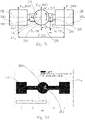
- FIG 3a An aircraft 100 according to the first aspect of the invention is shown in a highly schematic plan view. You can see in addition to those already associated with figure 1 described aircraft body 120, the drive devices 1F and 1R, their associated axes of rotation 5 and longitudinal direction 101 and transverse direction 102 also the center of mass S, 150 of the aircraft 100. The location or positioning of the center of mass S , 150 is to compensate for the in Drive devices 1 rotating in essentially the same direction of rotation caused unidirectional torques of central importance. This will be more detailed with regard to Figure 3b described.
- Figure 3b shows that in Figure 3a shown in top view aircraft according to the first aspect of the invention in side view and in a highly schematic representation.
- this side view only one of the two drive devices 1F arranged in the front area of the aircraft and one of the two drive devices 1R arranged in the rear area of the aircraft can be seen.
- the four driving devices 1F and 1R are arranged in a horizontal plane.
- the axes of rotation associated with the drive devices 1F and 1R are parallel to one another and parallel to the transverse direction (which points into the plane of the drawing).
- all four drive devices 1F, 1R rotate in the same direction of rotation 51 with a specific associated rotational speed.
- all driving devices 1F and 1R rotate clockwise, that is, all four driving devices are rotated with respect to the in Figure 3a specified transverse direction (y-axis) clockwise.
- the scalar product of each of the angular velocity vectors associated with the driving devices 1F, 1R and the unit vector in the transverse direction is positive.
- the propulsion devices rotate in such a way that the surface of the propulsion devices, which first encounters the air flow in forward flight, rotates against the direction of gravity.
- the Magnus effect has a particularly positive effect when the drive devices are rotated clockwise. This applies to any number of drive devices.
- a thrust vector is generated by the rotation of each drive device 1F, 1R.
- the thrust vector generated jointly by the two drive devices 1F arranged in the front area is denoted by F 1 , 701
- the thrust vector jointly generated by the two drive devices 1R arranged in the rear area is denoted by F 2 , 702 .
- all drive devices 1F and 1R rotate in the same direction of rotation 51
- all the resulting (drive) torques M 1 , 81 M2, 82 also act in the same direction, with M 1 , 81 being the (drive) torque of both front Driving devices 1F designates, and M 2 , 82 the (driving) torque of both rear driving devices 1R.
- Thrust vectors F 1 and F 2 can be adjusted to meet the two equilibrium conditions. Conveniently, the thrust vectors are adjusted by the thrust vector control. l 1 , 131 and l 2 , 132 give, based on the longitudinal direction, the distance of the center of gravity S , 150 from the drive devices 1 F im front area or 1 row in the back area. F S , 160 designates the weight of the entire aircraft.
- Torques M 1 , 81 and M 2 , 82 shown correspond to the driving torques of the two driving devices 1F and the two driving devices 1R, respectively.
- the proportionality factor a of each drive device is essentially dependent on the efficiency of the drive device, its angular velocity and other key figures of the drive device.
- Each drive device can have a different proportionality factor a .
- the values of a of different drive devices of the same type or size typically assume the same order of magnitude. Conveniently, they are essentially identical.
- Equation (9) can serve as a configuration formula for the aircraft. Equation (9) initially contains three freely selectable variables (from the set of F 1 , F 2 , l 1 , l 2 ), but equation (7) must still be observed in a stable flight attitude, which is why only two of the four mentioned above Sizes can be chosen freely.
- a pair i of propulsion devices can generate a maximum permissible (usually specified) thrust force/a maximum permissible thrust vector of F i,max . It is assumed that F i,max is greater than or equal to the shear forces F i,opt corresponding to the optimal configuration. This is due to the fact that an aircraft needs at least the thrust forces F i,opt in order to remain in a stable hover; In the preferred case, each pair of drive devices still applies an excess thrust, which can be used, among other things, for the deviation of the position of the center of gravity S , 150 from the optimal position.
- F i,max is the maximum thrust of a propulsion device allowed by the thrust vector control, which must therefore always be greater than or equal to the thrust for the optimal design F i,opt .
- the result is: f 1 , opt ⁇ f 1 , Max ⁇ f 2 , opt ⁇ f 2 , at least ⁇ f s ⁇ f 1 , Max .
- R Max f 1 , Max f 2 , at least .
- f 2 , opt ⁇ f 2 , Max ⁇ f 1 , opt ⁇ f 1 , at least ⁇ f s ⁇ f 2 , Max and thus a minimum allowable thrust vector ratio of R at least f 1 , at least f 2 , Max .
- center of mass S , 150 is outside the range l 1 at least ⁇ l 1 ⁇ l 1 Max , it is no longer possible to compensate for the deviation of the center of mass S , 150 from the optimal position according to equation (10) by the thrust forces F 1 , 701 or F 2 , 702 of the drive devices 1F or 1R.
- FIG. 3c serves to illustrate the area described above, in which the center of mass S , 150 of the aircraft can be expediently located for implementing the invention according to the first aspect.
- 3c 1 shows schematically an aircraft with drive devices 1F, 1R, which are arranged along two straight lines, each running parallel to the transverse direction of the aircraft.
- FIG 4 shows a further embodiment of an aircraft 100 according to the first aspect of the invention.
- This 4 serves primarily to generalize in connection with the Figures 3a, 3b and 3c derived results for any number K > 2 of drive devices 1.
- K > 2 of drive devices 1 It has already been pointed out above that it is for the considerations according to the invention primarily depends on the positioning of the drive devices 1 in the longitudinal direction. The drive devices can thus be positioned at different heights in the vertical direction.
- the longitudinal direction is in 4 marked as x-axis 101.
- the K propulsion devices of the aircraft are arranged along N > 1 straight lines g i . As already explained above, the said straight lines are not structural components of the aircraft 100, but only serve to clarify the geometric arrangement of the drive devices 1.
- the drive devices 1 are nevertheless on a straight line g i which runs parallel to the transverse direction 102 because their geometric center lies essentially on such a straight line g i ; is possible also to the condition of the arrangement to meet a parallel straight line that the bearing points of the drive devices 1 are essentially on such a straight line g i .
- the longitudinal positions x i of the straight line g i are fixed but arbitrary.
- the coordinate X S of the center of mass S , 150 can be calculated from equation (15) if the thrust vectors F i are specified; however, Equation (13) provides another condition that must be met for stable flight. Therefore, not all N thrust vectors F i can be specified arbitrarily, but only N ⁇ 1. This means that the position X S of the center of mass S , 150 is for a stable flight attitude, specifically hovering determined when N - 1 thrust vectors are given. The values of the specified thrust vectors can of course also be the same.
- a maximum permissible range for the (longitudinal, x) coordinate X S of the center of mass S , 150 can be analogous to the considerations for Figure 3b can also be determined for the general case described above, using equations (13), (14) and (15).
- FIG 5 shows an embodiment of the drive devices that can be used in an aircraft according to the invention.
- Each of these drive devices 1 is rotatably mounted about an axis of rotation.
- Each drive device 1 comprises a plurality of rotor blades 2, which are pivotably mounted about their longitudinal axis.
- the angle of inclination of the rotor blades 2 can thus be varied during the rotation of the drive device 1 .
- the speed of rotation of the drive devices 1, as well as the controller the angle of inclination of the rotor blades 2 the amount and the direction of the thrust vector generated can be varied.
- FIG 5 an inventive embodiment of a drive device 1 is shown in perspective.
- the drive device 1 is designed in the shape of a cylinder.
- the drive device 1 shown is a cyclogyro rotor.
- This drive device 1 comprises five rotor blades 2, each with an associated pitch mechanism 3, an offset device 4 and a disk 11.
- Drive devices with a different number of rotor blades are also possible.
- the rotor blades 2 are mounted so as to be rotatable about an axis of rotation of the drive device 1 .
- the offset device 4 defines an eccentric bearing axis which is mounted eccentrically with respect to the axis of rotation of the drive device 1 .
- the offset device is shown as an offset disk.
- the offset disc is freely rotatable around the eccentric bearing axis.
- the eccentric mounting of the offset disc 4 implies an eccentric mounting of the pitch mechanism 3.
- the eccentric mounting of the pitch mechanism 3 causes a change in the position of the rotor blades 2 during a revolution about the axis of rotation of the drive device 1.
- Each of the pitch mechanisms 3 shown comprises a coupling device 31 and a bearing device 33.
- Each rotor blade 2 is pivotably supported by the corresponding bearing device 33.
- the rotor blade 2 is mounted parallel to the axis of rotation of the drive device 1 about an axis. This axis is the rotor blade mounting axis 33.
- the rotor blade 2 can be mounted, for example, with the aid of a mounting means such as one or more pins, so-called main pins.
- the bearing means is preferably a part of the bearing device 33.
- the rotor blade bearing axis 33 can run through the center of mass of the rotor blade 2. However, the rotor blade 2 is preferably mounted at a distance from the center of mass.
- the coupling device 31 of the pitch mechanism 3 couples the rotor blade 2 to the offset device 4 in such a way that the rotor blade 2 performs a pitch movement when it rotates about the axis of rotation of the drive device 1, and provided that the eccentric bearing axis does not coincide with the axis of rotation of the drive device 1.
- An end piece of the coupling device 31 is coupled to the offset device 4 at a connection point.
- the other end piece of the coupling device 31 is coupled to the rotor blade 2 .
- the offset disc 4 is freely rotatable.
- the axis of rotation of the offset disk 4 preferably runs parallel to the axis of rotation of the drive device 1 at a certain offset distance.
- This offset distance can be adjustable.
- An offset device 4 with adjustable eccentricity can be realized, for example, by a planetary gear. A pitch movement of the rotor blades 2 occurs when the offset distance is not zero.
- the coupling device 31 is coupled to the rotor blade 2 at a coupling point 32.
- the coupling device 31 can comprise a coupling means.
- Drive device 1 shown includes the coupling device 31 a connecting rod (English “conrod") and a pin, so-called. Pitch link pin.
- the pin is a constructive embodiment of the coupling means according to the invention.
- the coupling device 31 is coupled to the rotor blade 2 at the coupling point 32 not by direct connection to the rotor blade 2, but by using a connecting element 61.
- One end of the connecting element 61 is rigidly connected to the rotor blade 2 . This connection is preferably made at the rotor blade mounting point.
- the other end of the connecting element 61 is coupled to the coupling device/connecting rod 31 . In this case, the pitch movement is introduced into the rotor blade 2 indirectly via the connecting element 61 via the coupling means with the aid of the connecting rod 31 .
- the coupling point 32 moves on a circular arc relative to the rotor blade mounting axis 33 when the rotor blade 2 rotates about the axis of rotation of the drive device 1. This brings about the pitch movement of the rotor blade 2 . This is therefore an oscillating movement of the rotor blade 2 about the rotor blade bearing axis 33.
- the diameter of the drive device 1 corresponds to twice the distance from the axis of rotation of the drive device 1 to the rotor blade bearing axis 33 or point. This diameter is relevant to the blade speed during rotation and therefore relevant to the thrust generated.
- the diameter is in the range between 150 mm and 2000 mm, preferably between 300 mm and 500 mm, and is particularly preferably 350 mm.
- the in figure 5 Drive device 1 shown has a disc 11.
- This disc 11 is designed in such a way that it aerodynamically separates the rotor blades 2 from the remaining components of the drive device 1.
- Such a disk 11 is particularly advantageous in the event that the drive device 1 is operated at higher speeds.
- the span of the drive device 1 is defined by the length of the rotor blades 2 .
- the span of the drive device 1 is the (longitudinal) distance between the two disks 11.
- the span of one of the cyclogyro rotors that can be used according to the invention is expediently a few centimeters to two meters, preferably between 350 and 420 mm.
- Several cyclogyro rotors are advantageously used in the aircraft according to the invention. Their ranges preferably deviate from one another by a maximum of 25%, expediently by a maximum of 10%.
- Their diameters preferably deviate from one another by a maximum of 25%, expediently by a maximum of 10%.
- Rotor blades 2 shown have a symmetrical profile; the invention is not limited to propulsion devices with rotor blades with a symmetrical profile.
- the drive device 1 generates thrust or a thrust vector based on two mutually coupled rotational movements.
- the first rotational movement is the rotation of the rotor blades 2 around the axis of rotation of the drive device 1.
- This first rotational movement leads to a movement of the rotor blades 2 along a circular path around the axis of rotation of the drive device.
- the rotor blade mounting axes 33 or rotor blade mounting points move along the circular path.
- Each rotor blade bearing axis 33 is parallel to the longitudinal axis of the rotor blades 2.
- the longitudinal axis of the rotor blades 2 is parallel to the axis of rotation of the drive device 1.
- the longitudinal axis of the rotor blades 2 is therefore also parallel to the rotor blade bearing axis 33.
- the thrust direction of the drive device 1 is normal to the axis of rotation of the drive device 1.
- all rotor blades 2 should be aligned as best as possible to the direction of flow at all times. This ensures that each rotor blade 2 makes a maximum contribution to the overall thrust.
- the inclination of each rotor blade 2 is continuously changed due to the pitch mechanism described above.
- Each rotor blade 2 carries out a periodic change in the angle of inclination or a pendulum movement. This is the pitch movement.
- the coupling point 32 moves on an arc of a circle around the rotor blade mounting axis 33. This is the second rotational movement.
- the magnitude and the direction of the thrust force generated and the associated thrust vector depend on the inclination of the rotor blades 2 .
- the distance between the eccentric mounting of the offset device 4 or the pitch mechanism 3 and the axis of rotation of the drive device 1 therefore influences the magnitude of the thrust force generated/the thrust vector generated.
- Pitch mechanisms 3 are only shown on one side of the drive device 1, it can be useful for reasons of stability to also attach corresponding pitch mechanisms to the opposite side of the drive device.
- the pitch mechanism can, for example, also be installed in the middle of the drive unit.
- FIG 6 shows a perspective view of an aircraft 200 according to the second aspect of the invention with an aircraft fuselage 220 and a plurality of drive devices 1A and 1B.
- Four drive devices 1A and 1B which are arranged around the aircraft fuselage 220, can be seen.
- Each drive device 1A and 1B is connected to the aircraft body 220 via an arm 221 and 222, respectively.
- Each of the driving devices 1A and 1B can be mounted on the arms 221 and 222, respectively, with appropriate mounting or bearing means. The presence of arms 221 and 222 is not essential.
- the Drive devices 1A and 1B can also be coupled to aircraft fuselage 220 in some other way.
- the aircraft body 220 and the drive devices 1A and 1B lie essentially in one plane here.
- the aircraft 200 shown can be, for example, an aircraft, a manned aircraft, a drone or what are known as micro air vehicles (MAVs).
- MAVs micro air vehicles
- a reference system which defines a first direction 201, a second direction 202 and a vertical direction 203 or vertical axis.
- the vertical direction 203 or axis corresponds to the direction of gravity when the aircraft 200 is resting on the ground.
- the vertical direction 203 is perpendicular to the aforementioned plane in which the aircraft body 220 and the propulsion devices 1A and 1B lie.
- the first direction 201 and the second direction 202 or the associated axes lie in said plane and are therefore each perpendicular to the vertical direction.
- the first direction 201 and the second direction 202 are not parallel to one another. In the exemplary embodiment shown, the first direction 201 and the second direction 202 are perpendicular to one another.
- the aircraft 200 shown has four drive devices 1A and 1B.
- the drive devices 1A and 1B shown are cyclogyro rotors. A more detailed description of cyclogyro rotors has already been given in connection with figure 5 given.
- Each drive device 1A and 1B is rotatably mounted about an axis of rotation 5 assigned to it.
- Each drive device 1A and 1B comprises a plurality of rotor blades 2 which are pivotably mounted about their longitudinal axis.
- the angle of inclination of the rotor blades 2 can thus be varied during the rotation of the drive device 1A or 1B.
- the rotational speed also referred to below as rotational speed
- the angle of inclination of the rotor blades 2 By controlling the rotational speed (also referred to below as rotational speed) of the drive devices 1A or 1B and by controlling the angle of inclination of the rotor blades 2, the amount and direction of the thrust force generated or the thrust vector describing it can be varied.
- the four driving devices 1A and 1B essentially form the corners of a rectangle or square.
- the fuselage 220 is positioned in the geometric center of this rectangle or square.
- each of the drive devices 1A and 1B is equidistant from the center or body.
- the arms 221 and 222 can have the same length.
- the driving devices 1A and 1B are arranged at the corners of a square.
- the two drive devices 1A corresponding to opposite corners of said rectangle or square lie on a common straight line; in the example shown, this straight line is substantially parallel to the first direction 201; likewise, the two drive devices 1B, which also correspond to opposite corners of said rectangle or square, lie on a common straight line substantially parallel to the second direction 202.
- the straight lines mentioned do not necessarily have to be a common axis of rotation to which the drive devices are (rigidly) coupled.
- Each drive device 1A, 1B can rotate via its own axis of rotation 5A, 5B assigned to it, and it is also possible for each of the drive devices 1A, 1B to be controlled individually, in particular in order to control its rotational speed separately.
- FIG 6 essentially aligned in the first direction 201 .
- the exemplary embodiment of FIG 6 substantially aligned in the first direction 202 .
- the axes of rotation 5A, 5B are not aligned exactly parallel to the first direction 201 or second direction 202. In fact, it is already in accordance with the invention when each of the associated axes of rotation 5A, 5B is essentially aligned in the first direction 201 or second direction 202.
- an axis of rotation 5A is essentially aligned in the first direction 201 if the angle enclosed between the axis of rotation 5A and an axis that runs in the first direction 201 and intersects the axis of rotation 5A is less than 45°, preferably is less than 30°, more preferably less than 15°.
- the designation "substantially aligned in the first direction” therefore does not rule out that the axes of rotation 5A are also exactly parallel to the first direction 201 .
- the aircraft 200 according to the invention is designed in such a way that it can hover in that each of the two drive devices 1A shown rotates essentially in the same direction of rotation about the respectively associated axis of rotation 5A, and/or each of the two drive devices 1B shown essentially rotates in the same direction of rotation the respectively associated axis of rotation 5B rotates.
- the structural restrictions that result from this for the aircraft 200 in connection with the other figures, in particular Figures 7a and 7b explained.
- FIG 7a an aircraft 200 according to the second aspect of the invention is shown in a highly schematic top view.
- the drive devices 1A 1 , 1A 2 and 1B 3 , 1B 4 the respective axes of rotation 5A or 5B assigned to them, the first direction 201 and second direction 202; the first direction 201 is perpendicular to the second direction 202.
- the center of mass S , 250 of the aircraft 200 is shown.
- the location or positioning of the center of mass S , 250 is of central importance for balancing the torques in the same direction caused by the drive devices 1A 1 , 1A 2 or 1B 3 , 1B 4 rotating in essentially the same direction of rotation. This will be more detailed with regard to Figure 7b described.
- the center of mass S , 250 is positioned in such a way that the aircraft 200 uses the Magnus effect both in forward flight in the (positive) first direction 201 (corresponding here to the positive x-direction) and in forward flight in the (positive) second direction 202 (corresponding here to the positive y-direction).
- the propulsion devices 1B 3 , 1B 4 rotate substantially in the same direction of rotation about the associated rotation axes 5B, advantageously clockwise.
- the scalar product of each of the angular velocity vectors associated with the drive devices 1B 3 , 1B 4 and the unit vector in the second direction is positive.
- the propulsion devices 1B 3 , 1B 4 rotate in such a way that the surface of the propulsion devices 1B 3 , 1B 4 , which first encounters the air flow in forward flight, rotates against the direction of gravity. If the aircraft 200 moves in forward flight in the second direction 202, the drive devices 1A 1 , 1A 2 rotate essentially in the same direction of rotation about the associated axes of rotation 5A, specifically advantageously in a counterclockwise direction. The definition given above applies accordingly. in the in Figure 7a In the coordinate system shown, this means that the scalar product of each of the vectors of the angular velocity associated with the drive devices 1A 1 , 1A 2 with the unit vector in the first direction is negative.
- the propulsion devices 1A 1 , 1A 2 rotate in such a way that the surface of the propulsion devices 1A 1 , 1A 2 , which first encounters the air flow in forward flight, rotates against the direction of gravity.
- the thrust vectors F 1 , 2001; F2 , 2002 ; F3 , 2003 ; and F 4 , 2004, which are generated due to the rotation of the drive devices about the axes of rotation 5A and 5B, respectively.
- the thrust vectors F 1 , 2001; F2 , 2002 ; F3 , 2003 ; and F 4 , 2004 point out of the image plane, ie lift is generated.
- FIGS 7b and 7c show that in Figure 7a shown in top view aircraft according to the second aspect of the invention in different side views and in strong schematic representation.
- the two driving devices 1A 1 , 1A 2 and one of the two driving devices 1B 3 , 1B 4 can be seen.
- the two driving devices 1B 3 , 1B 4 and one of the two driving devices 1A 1 , 1A 2 can be seen.
- the axes of rotation 5A assigned to the drive devices 1A 1 , 1A 2 are parallel to the first direction 201 (here: x-direction); the axes of rotation 5B assigned to the drive devices 1B 3 , 1B 4 are parallel to the second direction (here: y-direction) (which points into the plane of the drawing).
- the drive devices 1B 3 , 1B 4 are intended to rotate in the same direction of rotation 251 with a specific associated rotational speed.
- the two driving devices 1B 3 , 1B 4 rotate clockwise as defined above.
- a thrust vector is generated by the rotation of each drive device 1B 3 , 1B 4 .
- the propulsion devices 1A 1 , 1A 2 generate thrust vectors F 1 , 2001; and F 2 , 2002.
- the direction of rotation of the drive devices 1A 1 , 1A 2 is not important in the present consideration, which relates to a favorable design of the aircraft for forward flight in the first direction 201 .
- the (magnitudes of) thrust vectors F 1 , F 2 and F 34 can be adjusted to satisfy the two equilibrium conditions. Conveniently, the thrust vectors are adjusted by the thrust vector control.
- Torque M 34 , 280 shown corresponds to the (drive) torque of both drive devices 1B 3 , 1B 4 .
- Each drive device can have a different proportionality factor a .
- the values of a of different drive devices of the same type or size typically assume the same order of magnitude. Conveniently, they are essentially identical.
- F 1 , F 2 denote the magnitudes of the thrust vectors F 1 , 2001 generated by the propulsion devices 1A 1 and 1A 2 , respectively; F2 , 2002 ; l 1 , 231 the distance of the thrust vector F 1 , 2001 from the center of mass S , 250 of the aircraft determined in relation to the first direction (whereby this distance l 1 is related to the distance in relation to the first direction between the center of mass S , 250 of the aircraft and the geometric center along the axis of rotation 5A of the propulsion device 1A 1 , in other words: l 1 is the distance in relation to the first direction from the center of mass S , 250 of the aircraft to half the span of the propulsion device 1A 1 ); l 2 , 232 the distance, determined in relation to the first direction, of the thrust vector F 2 , 2002 from the center of mass S , 250 of the aircraft (whereby this distance l 2 is related to the distance in relation to the first direction between the center of mass S , 250 of the aircraft and the geometric center
- Equation (19) can serve as a configuration formula for the aircraft. Equation (19) initially contains four freely selectable quantities (from the set of F 1 , F 2 , F 34 , l 1 , l 2 , l 34 ), but in a stable flight attitude, Equation (17) must still be observed, which is why only three of the four sizes mentioned above can be freely selected.
- M 12 , 285 is the total torque produced by the driving devices 1A 1 , 1A 2 .
- F 3 , F 4 denote the magnitudes of the thrust vectors F 3 , 2003 generated by the propulsion devices 1B 3 and 1B 4 , respectively; F 4 , 2004 (cf. Figure 7a ); l 3 , 236, the distance of the thrust vector F 3 from the center of mass S , 250 of the aircraft determined in relation to the second direction (whereby this distance l 3 is related to the distance in relation to the second direction between the center of mass S , 250 of the aircraft and the geometric center of the Propulsion device 1B 3 can be identified along the axis of rotation 5B, in other words: l 3 is the distance in relation to the second direction from the center of mass S , 250 of the aircraft to half the span of the propulsion device 1B 3 ); l 4 , 237, the distance of the thrust vector F 4 from the center of mass S , 250 of the aircraft determined in relation to the second direction (whereby this distance l 4 is related to the distance in relation to the second direction between the center of mass S , 250 of the aircraft and the
- equations (17), (18), (20) and (21) the number of freely definable thrust vectors is to be determined using equations (17), (18), (20) and (21). Assuming that the positions of the driving devices are fixed, the following unknowns are present in the said equations: F 1 , F 2 , F 3 , F 4 , l 12 and l 34 . Furthermore, it must be noted that equations (17) and (20) specify the identical constraint. So you have three equations for six unknowns. The center of mass is to be determined using l 12 and l 34 ; thus equations (17), (18), (20) and (21) still define a thrust vector; three of the four thrust vectors F 1 , F 2 , F 3 can thus be specified as desired. If further boundary conditions are taken into account, the number of freely definable thrust vectors is reduced accordingly.
- a range is defined below in which the center of mass S , 250 can lie, so that it is still possible to balance the torque with the thrust forces/thrust vectors F 1 , 2001, F 2 , 2002 of the pairs of drive devices 1A 1 , 1A 2 or to assist in torque balancing with the thrust forces/thrust vectors F 3 , 2003, F 4 , 2004 of the pairs of propulsion devices 1B 3 , 1B 4 .
- one of the drive devices 1A 1 , 1A 2 , 1B 3 , 1B 4 can generate a maximum permissible (usually predetermined) thrust force/maximum permissible thrust vector of F i,max . It is assumed that F i,max is greater than or equal to the thrust forces F i,opt corresponding to the optimal configuration (as already described in more detail in connection with the first aspect of the invention).
- Equation (24a) can be used to specify the permissible range (28) in the first direction with respect to the axes of rotation of the drive devices 1B 3 , 1B 4 or the straight line that runs through the drive devices 1B 3 , 1B 4 . Then the area is specified using the distance l 34 and corresponding limits l 34, min and l 34, max .
- Equation (24b) can be used to specify the permissible range (29) in the second direction with respect to the axes of rotation of the drive devices 1A 1 , 1A 2 or the straight line that runs through the drive devices 1A 1 , 1A 2 . Then the Specify the area using the distance l 12 and corresponding limits l 12, min and l 12, max .
- Figure 7d serves to illustrate the area described above, in which the center of mass S , 250 of the aircraft can be expediently located for implementing the invention according to the second aspect.
- the center of mass is expediently located 1.05 to 1.15 m in relation to the first direction from the geometric center of the front of the two drive devices 1A 1 in relation to the forward flight direction.
- equation (27a) this result can also be expressed as follows: the center of mass is conveniently located 0.05 to 0.15 m from the axis of rotation of the driving devices 1B3, 1B4 and 1B4, respectively, with respect to the first direction. of the straight line passing through the two driving devices 1B 3 , 1B 4 .
- the center of mass S , 250 is appropriately positioned with respect to the plane defined by the propulsion devices and the aircraft fuselage in a square area, which is determined by the specified limits. Positioning with respect to the vertical direction is not limited.
- the second aspect according to the invention is not limited to aircraft with four drive devices. It is also possible, for example, for more than two drive devices to be arranged along one direction, or also for some drive devices to be arranged on straight lines parallel to one another.
- Equations (17), (18), (20), (21) are now generalized for an aircraft according to the invention with n, n >2 drive devices 1C.
- Figure 8a shows a section of such an aircraft in plan view;
- Figure 8b a section of the aircraft in side view.
- the origin O of the coordinate system lies in the geometric center of the aircraft.
- r i , i ⁇ ⁇ 1, ..., n ⁇ be the position vectors to the i-th thrust vector of the corresponding propulsion devices 1C.
- s is the position vector to the center of mass S , 250 of the aircraft.
- the propulsion devices rotate with the angular velocity ⁇ i ,i ⁇ ⁇ 1,..., n ⁇ , which are vectors lying in the xy-plane.
- An appropriate range with regard to the plane in which the propulsion devices 1C and the aircraft fuselage 220 lie can thus also be determined in the more general case considered here, in which the thrust vectors of one or more of the n propulsion devices 1C are varied and it is required that the Center of mass S , 250 must be positioned in such a way (cf. Equation (33)) that the torque compensation according to Equation (32) can be compensated for by the thrust forces/thrust vectors of the drive devices. For this purpose, it can be expedient to drive one or more of the drive devices with the maximum permissible thrust.
- the optimal position of the center of mass in the considered configuration is determined by the intersection of two straight lines, it is expedient to consider the first direction and/or the second direction, along which the drive devices rotate essentially in the same direction, as the directions , which are perpendicular to two given directions of forward flight.
- the The center of mass is therefore preferably (i) displaced from the geometric center with respect to a direction perpendicular to the first direction and lying in the plane defined by the propulsion devices and the aircraft fuselage, and/or (ii) with respect to a direction perpendicular to the second direction and in shifted from the geometric center in the plane defined by the propulsion devices and the aircraft fuselage.
- Figure 9a 12 shows an exemplary embodiment according to the second aspect of the invention, in which three drive devices 1C 1 , 1C 2 , 1C 3 are arranged around the aircraft fuselage 220 of the aircraft in such a way that they form the corners of an equilateral triangle. It is shown that the driving devices 1C 1 and 1C 2 are arranged on a straight g 1 ; g 1 defines the first direction according to the invention. In the exemplary embodiment shown, the drive device 1C 3 is arranged on a straight line g 2 which is perpendicular to the straight line g 1 and runs through the geometric center G of the aircraft, in this case through the geometric center G of the equilateral triangle. The straight line g 2 defines the second direction according to the invention.
- the axes of rotation 5C 1 , 5C 2 , 5C 3 of the drive devices 1C 1 , 1C 2 and 1C 3 point here towards the geometric center G (or away from it). In the exemplary embodiment shown, only the axis of rotation 5C 3 is aligned exactly parallel to the second direction defined by g 2 .
- the axes of rotation 5C 1 , 5C 2 are not exactly parallel to the first direction defined by g 1 .
- angles fall under the concept according to the invention of axes of rotation essentially aligned in the first direction.
- the angles can preferably also be selected to be smaller. If the drive devices 1C 1 , 1C 2 rotate around these axes of rotation essentially in the same direction of rotation as defined above, the inventive effect also occurs here if the aircraft moves in particular along the second direction defined by g 2 . If the drive devices 1C 1 , 1C 3 rotate about the associated axes of rotation 5C 1 or 5C 3 essentially in the same direction of rotation, the advantage according to the invention has a positive effect in particular when moving along the bisecting line 1C 1 -G -1C 3 .
- Figure 9b 1 shows an aircraft according to the second aspect of the invention, in which seven drive devices 1C 1 , . . . , 1C 7 are arranged in a plane around the aircraft fuselage 220.
- the driving devices 1C 1 ,..., 1C 7 are arranged so as to form the corners of a regular heptagon.
- Each of the drive devices is rotatably mounted about an associated axis of rotation 5C 1 , ..., 5C 7 .
- the axes of rotation 5C 1 , . . . , 5C 7 point to the geometric center G of the aircraft or the heptagon.
- the associated axes of rotation 5C 1 , ..., 5C 2j+1 should point towards the geometric center G (or away from it).
- a first straight line g 1 such that passes through two drive devices 1C 1 and 1C ( n +1)/2 ; this straight line g 1 defines the first direction according to the invention.
- Figure 9c 12 shows an aircraft according to the second aspect of the invention, in which six drive devices 1C 1 , . . . , 1C 6 are arranged in a plane around the aircraft fuselage 220.
- the driving devices 1C 1 ,..., 1C 6 are arranged so as to form the corners of a regular hexagon.
- Each of the drive devices is rotatably mounted about an associated axis of rotation 5C 1 , ..., 5C 6 .
- the embodiment shown show the axes of rotation 5C 1 , ..., 5C 6 to the geometric center G of the aircraft or the hexagon.
- the aircraft fuselage 220 is located between two opposing drive devices of the regular 2 j corner.
- the associated axes of rotation 5C 1 , ..., 5C 2j should point towards (or away from) the geometric center G.
- it is convenient to consider a first straight line g 1 such that passes through two drive devices 1C 1 and 1C n /2+1 ; this straight line g 1 defines the first direction according to the invention.
- the axes of rotation of the drive devices arranged on the straight lines g 1 and g 2 are aligned (mathematically exactly) parallel in the first or second direction.
- the first and second directions are particularly preferably essentially perpendicular, specifically: perpendicular to one another; this is always possible when the drive devices form the corners of a 4 j corner.
Priority Applications (6)
| Application Number | Priority Date | Filing Date | Title |
|---|---|---|---|
| EP21175290.2A EP4091939A1 (fr) | 2021-05-21 | 2021-05-21 | Aéronef |
| KR1020237043174A KR20240007680A (ko) | 2021-05-21 | 2022-05-23 | 항공기 |
| CA3220601A CA3220601A1 (fr) | 2021-05-21 | 2022-05-23 | Aeronef |
| CN202280035810.3A CN117355463A (zh) | 2021-05-21 | 2022-05-23 | 飞行器 |
| PCT/EP2022/063841 WO2022243559A1 (fr) | 2021-05-21 | 2022-05-23 | Aéronef |
| BR112023023953A BR112023023953A2 (pt) | 2021-05-21 | 2022-05-23 | Aeronave, método de fabricação de uma aeronave, e, método para controle de uma aeronave |
Applications Claiming Priority (1)
| Application Number | Priority Date | Filing Date | Title |
|---|---|---|---|
| EP21175290.2A EP4091939A1 (fr) | 2021-05-21 | 2021-05-21 | Aéronef |
Publications (1)
| Publication Number | Publication Date |
|---|---|
| EP4091939A1 true EP4091939A1 (fr) | 2022-11-23 |
Family
ID=76059751
Family Applications (1)
| Application Number | Title | Priority Date | Filing Date |
|---|---|---|---|
| EP21175290.2A Pending EP4091939A1 (fr) | 2021-05-21 | 2021-05-21 | Aéronef |
Country Status (6)
| Country | Link |
|---|---|
| EP (1) | EP4091939A1 (fr) |
| KR (1) | KR20240007680A (fr) |
| CN (1) | CN117355463A (fr) |
| BR (1) | BR112023023953A2 (fr) |
| CA (1) | CA3220601A1 (fr) |
| WO (1) | WO2022243559A1 (fr) |
Citations (5)
| Publication number | Priority date | Publication date | Assignee | Title |
|---|---|---|---|---|
| EP3354566A1 (fr) * | 2017-01-26 | 2018-08-01 | AIRBUS HELICOPTERS DEUTSCHLAND GmbH | Unité de propulsion avec deux rotors et un carénage |
| US20190071174A1 (en) * | 2016-03-15 | 2019-03-07 | Navis S R L | Vertical take off and landing aircraft with four tilting wings and electric motors |
| US10384776B2 (en) * | 2017-02-22 | 2019-08-20 | Bell Helicopter Textron Inc. | Tiltrotor aircraft having vertical lift and hover augmentation |
| EP3548378A1 (fr) | 2017-12-14 | 2019-10-09 | CycloTech GmbH | Dispositif d'entraînement pour un engin volant |
| US20200086984A1 (en) * | 2018-09-17 | 2020-03-19 | Amazon Technologies, Inc. | Six degree of freedom aerial vehicle having reconfigurable motors |
-
2021
- 2021-05-21 EP EP21175290.2A patent/EP4091939A1/fr active Pending
-
2022
- 2022-05-23 CA CA3220601A patent/CA3220601A1/fr active Pending
- 2022-05-23 KR KR1020237043174A patent/KR20240007680A/ko unknown
- 2022-05-23 WO PCT/EP2022/063841 patent/WO2022243559A1/fr active Application Filing
- 2022-05-23 BR BR112023023953A patent/BR112023023953A2/pt unknown
- 2022-05-23 CN CN202280035810.3A patent/CN117355463A/zh active Pending
Patent Citations (6)
| Publication number | Priority date | Publication date | Assignee | Title |
|---|---|---|---|---|
| US20190071174A1 (en) * | 2016-03-15 | 2019-03-07 | Navis S R L | Vertical take off and landing aircraft with four tilting wings and electric motors |
| EP3354566A1 (fr) * | 2017-01-26 | 2018-08-01 | AIRBUS HELICOPTERS DEUTSCHLAND GmbH | Unité de propulsion avec deux rotors et un carénage |
| US10384776B2 (en) * | 2017-02-22 | 2019-08-20 | Bell Helicopter Textron Inc. | Tiltrotor aircraft having vertical lift and hover augmentation |
| EP3548378A1 (fr) | 2017-12-14 | 2019-10-09 | CycloTech GmbH | Dispositif d'entraînement pour un engin volant |
| EP3715249A1 (fr) | 2017-12-14 | 2020-09-30 | CycloTech GmbH | Dispositif d'entrainement pour un aéronef |
| US20200086984A1 (en) * | 2018-09-17 | 2020-03-19 | Amazon Technologies, Inc. | Six degree of freedom aerial vehicle having reconfigurable motors |
Non-Patent Citations (2)
| Title |
|---|
| I.S. HWANG ET AL.: "Development of a Four-Rotor Cyclocopter", JOURNAL OF AIRCRAFT, vol. 45, no. 6, November 2008 (2008-11-01), pages 2151 |
| M. BENEDICT ET AL.: "Experimental Optimization of MAV-Scale Cycloidal Rotor Performance", JOURNAL OF THE AMERICAN HELICOPTER SOCIETY, vol. 56, 2011, pages 022005 |
Also Published As
| Publication number | Publication date |
|---|---|
| WO2022243559A1 (fr) | 2022-11-24 |
| CN117355463A (zh) | 2024-01-05 |
| BR112023023953A2 (pt) | 2024-01-30 |
| CA3220601A1 (fr) | 2022-11-24 |
| KR20240007680A (ko) | 2024-01-16 |
Similar Documents
| Publication | Publication Date | Title |
|---|---|---|
| DE102013020601B4 (de) | Flugzeugkonfiguration | |
| EP2817219B1 (fr) | Aéronef | |
| DE102012202698B4 (de) | Fluggerät | |
| EP0857648B1 (fr) | Aéronef pour le transport des passagers et du fret | |
| DE60210512T2 (de) | Senkrecht startendes und landendes flugzeug | |
| DE102005046155B4 (de) | Hubschrauber mit koaxialen Hauptrotoren | |
| EP3397551B1 (fr) | Aéronef | |
| EP3715249B1 (fr) | Dispositif d'entrainement pour un aéronef | |
| EP3176084A1 (fr) | Procédé d'amélioration des qualités de vol d'un muticoptère dans des situations de panne et multicoptère présentant des qualités de vol améliorées dans des situations de panne | |
| DE2922059A1 (de) | Verbundflugzeug | |
| WO2017021391A1 (fr) | Aéronef adav à masse mobile pour la commande | |
| DE102011012503A1 (de) | Ultraleichtes Luftfahrzeug | |
| DE102012002310A1 (de) | Flugzeug mit mindestens zwei Flugzeugrümpfen und einer ersten Tragflügelanordnung mit mindestens zwei nicht verbundenen Tragflügelabschnitten | |
| DE6923742U (de) | Flugzeug | |
| EP4091939A1 (fr) | Aéronef | |
| DE202019000936U1 (de) | Universalflugerät mit Elektroantrieb | |
| DE112020004732T5 (de) | Elektroflugzeug und Lageregelungsverfahren dafür | |
| DE102016001771A1 (de) | Kippflügel-Wandelflugzeug | |
| DE102012023821A1 (de) | Flugzeug mit mindestens zwei Flugzeugrümpfen und zwei Hauptflügeln | |
| DE102020107437A1 (de) | Luftfahrzeug mit 3-dimensionaler, aerodynamischer und multifunktionaler Ausführung | |
| DE102022114599B4 (de) | Fluggerät | |
| DE102019107593A1 (de) | Flugvorrichtung | |
| DE102017128164B4 (de) | Flugzeug | |
| DE573958C (de) | Anordnung von Propellern an einem gasgefuellten Luftfahrzeug | |
| DE60026394T2 (de) | Kipprotorflugzeug |
Legal Events
| Date | Code | Title | Description |
|---|---|---|---|
| PUAI | Public reference made under article 153(3) epc to a published international application that has entered the european phase |
Free format text: ORIGINAL CODE: 0009012 |
|
| STAA | Information on the status of an ep patent application or granted ep patent |
Free format text: STATUS: REQUEST FOR EXAMINATION WAS MADE |
|
| 17P | Request for examination filed |
Effective date: 20220615 |
|
| AK | Designated contracting states |
Kind code of ref document: A1 Designated state(s): AL AT BE BG CH CY CZ DE DK EE ES FI FR GB GR HR HU IE IS IT LI LT LU LV MC MK MT NL NO PL PT RO RS SE SI SK SM TR |
|
| STAA | Information on the status of an ep patent application or granted ep patent |
Free format text: STATUS: EXAMINATION IS IN PROGRESS |
|
| 17Q | First examination report despatched |
Effective date: 20230419 |