EP3587335A2 - Handlaufumlenkvorrichtung für fahrtreppen und fahrsteige mit einem aus einer vielzahl von segmenten gebildeten handlaufumlenkband, sowie handlaufumlenkband und segment eines handlaufumlenkbandes - Google Patents
Handlaufumlenkvorrichtung für fahrtreppen und fahrsteige mit einem aus einer vielzahl von segmenten gebildeten handlaufumlenkband, sowie handlaufumlenkband und segment eines handlaufumlenkbandes Download PDFInfo
- Publication number
- EP3587335A2 EP3587335A2 EP19168980.1A EP19168980A EP3587335A2 EP 3587335 A2 EP3587335 A2 EP 3587335A2 EP 19168980 A EP19168980 A EP 19168980A EP 3587335 A2 EP3587335 A2 EP 3587335A2
- Authority
- EP
- European Patent Office
- Prior art keywords
- handrail
- segment
- engagement element
- guide profile
- segments
- Prior art date
- Legal status (The legal status is an assumption and is not a legal conclusion. Google has not performed a legal analysis and makes no representation as to the accuracy of the status listed.)
- Granted
Links
Images



Classifications
-
- B—PERFORMING OPERATIONS; TRANSPORTING
- B66—HOISTING; LIFTING; HAULING
- B66B—ELEVATORS; ESCALATORS OR MOVING WALKWAYS
- B66B23/00—Component parts of escalators or moving walkways
- B66B23/22—Balustrades
-
- B—PERFORMING OPERATIONS; TRANSPORTING
- B66—HOISTING; LIFTING; HAULING
- B66B—ELEVATORS; ESCALATORS OR MOVING WALKWAYS
- B66B23/00—Component parts of escalators or moving walkways
-
- B—PERFORMING OPERATIONS; TRANSPORTING
- B66—HOISTING; LIFTING; HAULING
- B66B—ELEVATORS; ESCALATORS OR MOVING WALKWAYS
- B66B23/00—Component parts of escalators or moving walkways
- B66B23/22—Balustrades
- B66B23/24—Handrails
Definitions
- the invention relates to a segment of a handrail deflecting belt for use with a w-shaped handrail guide profile, the handrail guide profile having a first depression, an elevation and a second depression between two lateral walls.
- the segment comprises a base body with a support surface for resting on the elevation of the handrail guide profile, an axial section extending to the side of the support surface in the transverse direction of extension of the base body for receiving a rolling body.
- the invention further relates to a handrail deflection belt formed from a plurality of segments and to a handrail deflection device with a w-shaped handrail guide profile which has a first depression, an elevation and a second depression between two lateral walls, and with a handrail deflection belt formed from a plurality of segments.
- Escalators and moving walks usually have a balustrade with a powered, endless handrail. It is known to guide and redirect the handrail of an escalator or moving walk, in particular in the deflection area of the handrail, that is to say at the ends of the balustrade, via rolling bodies. This enables the handrail to be guided smoothly and evenly, which has a positive effect on the wear of the handrail and the smoothness of the handrail. Different solutions have been developed for this.
- a handrail deflection device with a handrail guided over the balustrade is known, the handrail having a plurality of ball bearings arranged one behind the other, over which the handrail rolls.
- a handrail deflection device which comprises a w-shaped handrail guide profile and a flexible element arranged in it with roller bearings.
- a handrail deflection device with a w-shaped handrail guide profile is known.
- a handrail chain is included in the handrail guide profile a plurality of segments designed as slide bearing supports are arranged, wherein rollers are arranged on the segments, via which a handrail can roll.
- the DE 20 2010 003 769 U1 discloses another handrail chain for the handrail guidance in the deflections at the top and bottom of escalators and moving walks.
- a disadvantage of the known solutions for guiding and deflecting a handrail of an escalator or moving walk is, inter alia, that a handrail band or a handrail chain formed can be set in motion, in particular in vibrations, by the moving handrail. These movements not only increase the wear on the handrail belt but also lead to perceptible noises, and thus to a reduction in comfort. If individual segments of a handrail band or a handrail chain are worn or defective, the replacement of the worn or defective segment is generally not possible or only possible at great expense.
- the convenience of use should be increased.
- simplified maintenance of a handrail deflection device is to be made possible.
- the proposed solution provides a segment of a handrail deflection belt for use with a w-shaped handrail guide profile, the handrail guide profile having a first depression, an elevation and a second depression between two side walls.
- the segment comprises a base body with a support surface for resting on the elevation of the handrail guide profile.
- On the side of the support surface an axial section extends from the base body in the direction of its transverse extent to accommodate a rolling body, in particular a roller or a rolling bearing.
- At least at one end of the base body in relation to its longitudinal direction of extension there is a first one Engagement element and a second engagement element arranged.
- the first engaging element and the second engaging element are designed such that the first engaging element and the second engaging element each extend to the side walls of the handrail guide profile, in particular parallel or substantially parallel to the respective axle section.
- Rolling bodies arranged on the axis sections of the segment can advantageously be freely rotated in the region of the respective depression, that is to say between the wall and the elevation.
- the segment is advantageously made of a plastic.
- the segment is formed in one piece, advantageously as an injection molded part. As a result, the manufacturing costs for such a segment are advantageously low.
- at least the axis sections are part of an axis connected to the segment, in particular an axis guided through the segment.
- the segment has a width between 25 mm (mm: millimeters) and 70 mm, preferably a width between 30 mm and 40 mm, from the end of the first axis section to the end of the second axis section.
- the diameter of the respective axle section is advantageously between 5 mm and 20 mm, preferably between 5 mm and 12 mm.
- the segment has a length between 25 mm and 70 mm, preferably between 30 mm and 45 mm. The length extends in particular from a first first engagement element to an opposite second first engagement element or from a first second engagement element to an opposite second second engagement element.
- the engagement elements of the segment advantageously give the segment stability when it is arranged in a handrail guide profile. Because the engagement elements extend towards the side walls of the handrail guide profile, the engagement elements in particular prevent or at least severely restrict lateral rotation of the segment resting on the bearing surface on the elevation of a handrail guide element. This restriction of the movement of the segment arranged in the handrail guide profile advantageously also reduces the development of noise when these segments are used for the handrail deflection.
- a second first engagement element and a second second engagement element are additionally arranged on the other end of the base body with respect to the direction of its longitudinal extent.
- the segment thus has a total of four engagement elements, namely two each at the opposite ends of the base body.
- the four engagement elements are advantageously designed in the same way.
- the second first engagement element and the second second engagement element are designed such that the second first engagement element and the second second engagement element each extend to the side walls of the handrail guide profile, in particular parallel or essentially parallel to the respective axle section.
- Two engagement elements therefore advantageously extend at a distance from each other towards one of the side walls of the handrail guide profile.
- This advantageously increases the security against rotation of the segment arranged in the handrail guide profile.
- the segment is symmetrical, preferably mirror-symmetrical, with respect to a longitudinal axis running centrally in the longitudinal direction of the segment.
- the segment is further advantageously symmetrical, preferably mirror-symmetrical, with respect to a central transverse axis. If the segment is mirror-symmetrical both with respect to a central longitudinal axis and with respect to a central transverse axis, this results in particular in the advantage that when inserting into a handrail guide profile, no errors can occur with regard to the orientation of the segment.
- the engagement elements extending to the side wall of the handrail guide profile touch the side wall.
- the first engagement element and the second engagement element are designed such that the first engagement element and the second engagement element can each be supported against the side walls of the handrail guide profile. This advantageously increases the security against rotation of the segment arranged in the handrail guide profile.
- the first engagement element is arranged at the end of a first arm extending from the base body in its longitudinal direction and the second engagement element is arranged at the end of a second arm extending in the longitudinal direction of the base body.
- the first arm and the second arm each form a pair of arms that are resilient in the transverse direction of extension of the base body.
- the arms arranged at the end of the base body can be pressed together against the force of a spring, that is to say in particular in such a way that the respective engagement element arranged at the ends of the arms towards the elevation can be moved.
- the engaging elements advantageously have a recess toward the elevations, so that the resilient arms do not directly abut the elevation with the engaging elements.
- the resilient design advantageously allows manufacturing tolerances in relation to the handrail guide profile to be even better compensated for.
- a clamping effect can advantageously be achieved for a segment inserted into a handrail guide profile by means of the engagement elements arranged on the spring arms, which are advantageously supported within the recesses of the handrail guide profile against the lateral walls of the handrail guide profile.
- the end of a respective arm forms the respective engagement element.
- the arm and engagement element are formed in one piece.
- An outwardly pointing branch of the first arm preferably forms the first engagement element and an outwardly directed branch of the second arm forms the second engagement element.
- the engagement elements are an extension of the respective arm in the transverse direction, which are further extended towards the depressions relative to the respective arm.
- the respective engagement element branches off at right angles from the respective arm.
- arm and engagement element or arm with engagement element each form an L-shape or T-shape.
- a further advantageous embodiment provides that the first engagement element and the second engagement element protrude beyond the base body in the direction of extent.
- this embodiment provides that the first engagement element and the second engagement element protrude beyond the base body on its side, on which the support surface is located, in the vertical direction.
- the engagement elements of the segment arranged in a handrail guide profile do not end at the level of the elevation of the handrail guide profile, but protrude further in the direction of the depressions into the handrail guide profile.
- the arrangement of the segment in the handrail guide profile is advantageously further stabilized and, in particular, further secured against twisting of the segment and against lateral tilting movements. This advantageously further reduces noise development when deflecting a handrail.
- the first engagement element and the second engagement element are further advantageously designed such that the first engagement element into the first recess of the handrail guide profile can engage and the second engagement element can engage in the second recess of the handrail guide profile. This advantageously increases the security against rotation of the segment arranged in the handrail guide profile.
- the engagement elements advantageously engage in the depressions of the handrail guide profile in such a way that the elevation of the handrail guide profile is arranged between the first engagement element and the second engagement element.
- the base body has two first engagement elements and two second engagement elements.
- two engagement elements advantageously engage at a distance from one another in the first recess of the handrail guide profile and two engagement elements are spaced apart from one another in the second recess of the handrail guide profile. This advantageously increases the security against rotation of the segment arranged in the handrail guide profile.
- the engagement elements advantageously slim down towards the depressions of the handrail guide profile.
- the engagement elements have an insertion bevel, by means of which insertion into a handrail guide profile is advantageously also possible with little effort if the handrail guide profile has large manufacturing tolerances, in particular with respect to the width of the depressions.
- the base body of the segment has a connection element on the side opposite the support surface.
- the connection element is advantageously designed for connection to a connection point of a connection element.
- the connecting element has, in particular, a large number of connection points for connecting a large number of segments to form a handrail deflection band.
- the connecting element is a band, preferably a metal band. Holes are preferably made as connection points in the metal strip, into which holes the connection elements of the segments for connection to the connection element are introduced.
- the segment is detachably connected to the connecting element via the connecting element in a non-destructive manner via a connecting point of the connecting element.
- segments are not directly connected to one another, but only via the connecting element.
- the connecting element is advantageously designed in accordance with at least one of the following ways: as a truncated cone; as a snap connection; as a connection element with an undercut; as a connection element with a ribbed structure.
- the connection points are each advantageously designed as a circular hole.
- a design of the connection element as a truncated cone is advantageous because the introduction into the connection point is facilitated by the upper end with the smaller radius.
- the connection element with the connection point can be pressed onto the connection element by the radius of the connection element designed as a truncated cone, which radius increases towards the base body.
- the truncated cone also has an undercut, the connecting element with the connection point being brought completely over the truncated cone and, as it were, an anti-loss device being provided by means of the undercut.
- ribs are advantageously applied to the connecting element, in particular to the connecting element designed as a truncated cone.
- the truncated cone is particularly advantageously designed as a snap connection, in particular in which the truncated cone is formed from a plurality of segments extending in the direction of vertical extension of the base body.
- the segment advantageously has a guide for the connecting element in the longitudinal direction of the main body.
- webs are provided in the longitudinal direction of the base body to the right and left of the connecting element, between which the connecting element, in particular the metal strip, is arranged. This guide further simplifies the connection of the segment to the metal strip and advantageously prevents the metal strip from rotating relative to the segment.
- axle sections are each designed to receive the rolling bodies as a snap connection.
- the axis sections are advantageously formed as part of the segment.
- the rolling bodies can advantageously be easily and captively attached to the respective axle section.
- rolling bearings are provided as rolling bodies, the inner ring of the Rolling bearing is advantageously fixed by the snap connection, so that only the outer ring of the respective rolling bearing can rotate.
- the handrail deflection belt for an escalator or moving walk which is also proposed to solve the problem mentioned at the outset, is intended in particular for use with a w-shaped handrail guide profile which has a first depression, an elevation and a second depression between two lateral walls.
- the handrail deflecting belt comprises a plurality of segments, on each of which at least one rolling element is arranged, the segments being connected to one another via a common connecting element, in particular a perforated metal belt.
- the individual segments are therefore not connected to one another as chain links, but rather the segments are connected to one another exclusively via the common connecting element.
- This configuration is particularly advantageous with regard to the replacement of individual segments of the handrail deflection belt, in particular in the event of a defect in one of the segments.
- the length of the handrail deflection belt can be adjusted better than with a chain, since the distances between the segments are not fixed.
- the segments can furthermore be connected more firmly to the handrail guide profile by means of the connecting element, which further restricts the mobility of the individual segments and thus contributes to noise reduction and increased user comfort.
- the choice of the length of the connecting element and the choice of the number of segments advantageously make it possible to easily produce a handrail deflection band of almost any length.
- the segments of the handrail deflection belt are designed as segments designed according to the invention, in particular as described above.
- the segments preferably have a connecting element, via which the segments are connected to the connecting element.
- the connecting element has holes as connection points. These holes are advantageously designed such that tearing out of the holes is prevented when used as intended.
- the connecting element is not designed as a perforated metal band, it is therefore provided that the holes have a reinforcement, for example a metal ring which delimits the respective hole from the outside.
- the segments have two axle sections, on each of which a roller or a roller bearing is arranged as a rolling body.
- the handrail deflection device for an escalator or moving walk which is further proposed to achieve the initially mentioned object, comprises a w-shaped handrail guide profile, in particular for arrangement on a balustrade end of an escalator or moving walk.
- the handrail guide profile comprises a first depression, an elevation and a second depression between two side walls. Walls, depressions and elevations form the w-shape in cross section.
- the handrail deflection device also has a plurality of segments designed according to the invention, in particular as described above.
- a rolling body, in particular a rolling bearing, is arranged on each of the axial sections of a respective segment.
- the segments are advantageously connected to one another via a common connecting element, in particular a metal perforated band, to form a handrail deflection band.
- a connecting element in particular a metal perforated band
- the connecting element can also have a fabric structure, in particular a fabric structure made of metal, plastic and / or textile.
- the handrail deflection band and the handrail guide profile are coordinated with one another such that a respective segment of the handrail deflection band rests with its contact surface on the elevation of the handrail guide profile, the engagement elements extend to the side walls of the handrail guide profile and that extend on the axial sections of a respective segment arranged rolling body can rotate freely in the region of the respective recess of the handrail guide profile around the respective axis section.
- the engagement elements of a respective segment are advantageously supported against the side walls.
- the engagement elements of a respective segment also advantageously engage in the depressions of the handrail guide profile.
- a handrail deflected by means of the handrail deflection device is advantageously guided over the rotatable rolling bodies, as a result of which the friction forces occurring in this area are advantageously low.
- the engagement elements of a respective segment advantageously suppress twisting, in particular lateral twisting, of the respective segment.
- the mobility of the segments is advantageously already limited, so that a uniform, low-noise deflection of the handrail is made possible.
- This positive effect is advantageously further increased in that the connecting element achieves a comparatively high contact pressure of the segments on the handrail guide profile, which further restricts the mobility of the individual segments.
- the segments are advantageously fixed between the elevation and the connecting element. This means in particular that the connecting element advantageously runs above the elevation.
- the segments are each connected to the connecting element at a distance. This means that adjacent segments advantageously do not touch directly. If a segment is not optimally arranged in the handrail guide profile, movements of this segment are advantageously not transferred or are significantly reduced to neighboring segments, which also advantageously contributes to the smooth running and thus to the high level of user comfort.
- the segments are connected to the connecting element via their connecting elements.
- the ends of the connecting element are each advantageously connected to the handrail guide profile, in particular to the elevation of the handrail guide profile. It is particularly provided that the connecting element is connected to the handrail guide profile by means of a screw connection. At least at one end of the connecting element, an elongated hole is advantageously made in the connecting element. In this way, the mechanical tension with which the handrail deflection belt is arranged on the handrail guide profile can advantageously be set.
- FIG. 1 Segment 1 of a handrail deflection belt shown is intended for use with a w-shaped handrail guide profile, which has a first depression, an elevation and a second depression between two lateral walls.
- a cross-sectional view of such a w-shaped handrail guide profile is shown, for example, in FIG Fig. 7 shown.
- This in Fig. 1 shown segment 1 has a base body 3.
- This base body 3 points to the in Fig. 1 not visible bottom of a support surface 4, with which the segment 1 can rest on the elevation of a w-shaped handrail guide profile.
- an axle section 5 which is fixedly connected to the segment 1, is arranged for receiving a rolling body.
- the axis sections 5 are here, as in Fig. 1 shown, designed as a snap connection. A roller or roller bearing can be applied as a rolling body to the respective axle section 5.
- the base body 3 forms in the Fig. 1 illustrated embodiment at each end with respect to the longitudinal direction 31 of the segment 1 from a first arm 8 and a second arm 9.
- a first arm 8 and a second arm 9 each form a pair of arms.
- the two pairs of arms of the segment 1 are designed to be elastically resilient, in particular in the transverse direction 30 of the base body 3.
- the first arm can be in each case 8 and press the second arm 9 against each other against the force of a spring, as in the case of a leg spring. Due to the resilient design, when introducing the segment 1 into a handrail guide profile, in particular manufacturing tolerances in relation to the handrail guide profile can be compensated. A clamping effect can also advantageously be achieved by means of which the segment 1 can be held better in the handrail guide profile.
- the segment 1 has a first engagement element 6 and at the end of the respective second arm 9 a second engagement element 7.
- the engagement elements 6, 7 are in the in Fig. 1
- the embodiment shown is designed as a right-angled branching of the first arm 8 or the second arm 9.
- the engagement elements 6, 7 are each extended downwards, that is to say that the two first engagement elements 6 and the two second engagement elements 7 project beyond the base body 3 on its side, on which the support surface 4 is located, in the direction of extent 32.
- the first engagement elements 6 and second engagement elements 7 arranged on the first arms 8 and the second arms 9 are further designed such that the first engagement elements 6 can engage in a first depression of a handrail guide profile and the second engagement elements 7 engage in a second depression of a handrail guide profile can. Furthermore, the engagement elements 6, 7 can be supported against the side walls of a handrail guide profile, which is further favored by the resilient arm pairs. The underside of the pairs of arms up to the engagement elements 6, 7 can also be designed as a support surface 4.
- the first engagement elements 6 and the second engagement elements 7 are also rounded off at the outer lower corners with an insertion bevel 15 and bevelled on the inner flank.
- connection element 10 designed as a snap connection.
- This connection element 10 is designed as a truncated cone connection, which facilitates the connection of a connection element with holes as connection points.
- webs 18 are also arranged which serve as a guide for the connecting element and in particular prevent a connecting element 50 connected to the segment 1 by means of the connecting element 10 with respect to the segment 1.
- the segment 1 is made as a one-piece injection molded plastic part.
- roller bearings 1 are arranged as rolling bodies 40 on the axis sections 5 of the segment.
- the inner ring of the respective rolling bearing is fixed by means of the axial sections 5 designed as a snap connection, so that only the outer ring of the rolling bearing can rotate freely and a handrail can be deflected via the rotating rolling bearing.
- the connecting element 10 of the segment 1 is not designed as a snap connection.
- the connecting element 10 of the segment 1 in this exemplary embodiment is designed as a truncated cone with an undercut 11, on the surface of which ribs 12 are arranged.
- This configuration of the connecting element 10 helps to introduce the connecting element 10 in a simplified manner into a hole of a connecting element provided as a connecting point and thereby to connect the connecting element which is brought about the truncated cone to the segment 1 in a captive manner, in particular without additional fastening elements such as screws or rivets need.
- the segment 1 has a length of 36 mm from a first engagement element 6 to an opposite second engagement element 7. Furthermore, the segment 1 has a width of 32.5 mm from the end of one axle section 5 to the end of the other axle section 5.
- the diameter within the inner ring of the rolling bearing is 8 mm in this exemplary embodiment.
- the outer diameter of the rolling bearing including the outer ring is 22 mm in this embodiment.
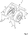
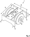
- Fig. 3 shows a further embodiment for a segment 1 of a handrail deflection belt for use with a w-shaped handrail guide profile.
- the segment 1 comprises a base body 3 with a support surface 4 for resting on the elevation of the handrail guide profile.
- An axle section 5 extends to the side of the support surface 4 in the transverse direction 30 of the base body 3 for receiving a rolling body 40.
- an axle is inserted into the base body 3 of the segment 1 in this exemplary embodiment, the ends of which protrude from the base body 3 as axle sections 5.
- a roller as a rolling body 40 is arranged on each of the axle sections 5.
- connection element 10 is in turn designed as a truncated cone with a circular recess 13 and an undercut 11 on the side of the base body 3 opposite the support surface 4.
- the first engagement elements 6 and the second engagement elements 7 are arranged on the base body 3 without arm pairs.
- the engagement elements 6, 7 are branched off at right angles from the base body 3 and have a greater height extension 32 than the base body 3, that is to say the engagement elements 6, 7 protrude beyond the base body 3 in the height extension direction on the side thereof on which the support surface 4 is located ,
- the engagement elements 6, 7 can in particular also be supported against the respective wall of the elevation of a handrail guide and thus contribute to improved security against rotation of a segment introduced into a handrail guide profile.
- the engaging elements 6, 7 each have insertion bevels 15 on the outer sides.
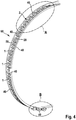
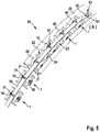
- FIG. 4 An exemplary embodiment of a handrail deflection device 60 for arrangement at the end of a balustrade of an escalator or a moving walk is shown. Details of the handrail deflection device 60 are also made with reference to the in FIG Fig. 5 and Fig. 6 illustrated exemplary embodiments, in which area A or area B are shown enlarged.
- the handrail deflection device 60 shown comprises a handrail guide profile 20 which is W-shaped with two lateral walls 21, a first depression 22, a second depression 24 and an elevation 23 arranged between the depressions 22, 24.
- the handrail guide profile 20 is in particular a metal profile, preferably a steel profile or an aluminum profile.
- the handrail deflection device 60 comprises a handrail deflection band 2 arranged in the handrail guide profile 20.
- the handrail deflection band 2 has a large number of segments 1, which in particular correspond to one of the exemplary embodiments in accordance with FIG Fig. 1 .
- Fig. 2 or Fig. 3 can be trained.
- a roller bearing is arranged as a rolling body 40 on the axle sections 5 of the respective segment 1, so that each segment 1 comprises a pair of roller bearings.
- the segments 1 of the handrail deflection belt 2 lie with their contact surface 4 on the elevation 23 of the handrail guide profile 20, as in particular Fig. 5 seen.
- the engagement elements 6, 7 of a respective segment 1 each extend to the side walls 21 and engage in the recesses 22, 24 of the handrail guide profile 20.
- the engagement elements 6, 7 are supported against the inside of the walls 21.
- the rolling bodies 40 designed as roller bearings are arranged in the area of the depressions 22, 24 and can rotate freely, so that a handrail guided by means of the handrail deflection device can roll over the roller bearings.
- the segments 1 of the handrail deflection band 2 of the handrail deflection device 60 are connected via their connecting elements 10 to a connecting element 50 of the handrail deflection band 2 designed as a metal band.
- the segments 1 are each spaced apart from one another on the connecting element 50.
- the segments 1 For connecting the segments 1 to the connecting element 50, the segments 1 have connecting elements 10 and the connecting element 50 have corresponding connecting points 51.
- connection points 51 are holes made in the metal strip, which in this exemplary embodiment is the connecting element 50. These are introduced into the metal strip at equidistant intervals. The distances between the holes can also vary.
- connection elements 10 as in connection with the reference to FIG Fig. 1 described embodiment described, are formed as a snap connection.
- the snap connection as connecting element 10 ensures that the respective segment 1 is firmly connected to the connecting element 50, but in the event of a defect the affected segment can simply be replaced.
- the connecting element 50 is also guided by a guide of the respective segment 1.
- This guidance is in particular by means of webs 18 arranged on the segments 1, as for example in FIG Fig. 1 shown, realized.
- an elongated hole 52 is made at a first end 54 of the connecting element 50, in this exemplary embodiment at the upper end of the connecting element 50, as in FIG Fig. 5 shown.
- the connecting element 50 is firmly connected to the handrail guide profile 20 by means of a screw connection 53.
- a threaded bolt can be welded into the handrail guide profile 20, the bolt being inserted into the elongated hole 52 of the connecting element 50 and the connecting element 50 being fixed with a screw nut.
- the elongated hole 52 advantageously offers the possibility of compensating for manufacturing tolerances in relation to the handrail guide profile 20, in particular the length and / or the curvature of the handrail guide profile 20.
- the elongated hole 52 can further advantageously be used to influence the mechanical tension with which the connecting element 50 presses the segments 1 of the handrail deflection band 2 against the handrail guide profile 20.
- the second end 55 of the connecting element 50 in this exemplary embodiment the lower end of the connecting element 50, can have a simple hole for mounting on a threaded bolt and for fixing by means of a screw connection 53, as in FIG Fig. 6 shown.
- the distance between two adjacent segments 1 is as in FIG 4 to 6 shown, advantageously less than the length of a segment 1, in particular less than half the length of a segment 1.
- FIG. 7 A cross section of a handrail guide device 60 is shown.
- the w-shaped cross section of the handrail guide profile 20, which is formed by the side walls 21 and the elevation 23 located between the first depression 22 and the second depression 24, can be seen particularly clearly.
- the handrail guide profile 20 and the segments 1 of the handrail guide device 60 are matched to one another in such a way that a respective segment 1 with its bearing surface 4 rests on the elevation 23 of the handrail guide profile.
- the first engagement elements 6 of each segment 1 extend to the one side wall 21 of the handrail guide profile 20 and thereby engage in the first recess 22 of the handrail guide profile 20 and the second engagement elements 7 of each segment 1 each extend to the other side wall 21 of the handrail guide profile 20 and engage in the second recess 24 of the handrail guide profile 20.
- the engagement elements 6, 7 are supported laterally against the respective side walls 21 of the handrail guide profile 20, which is particularly the case with the spring arms 8, 9 of the respective segment 1, as for example in FIG Fig. 1 shown, is further reinforced.
- the rolling bodies 40 designed as roller bearings are held on the axle sections 5 above the respective recess 22, 24, so that they can rotate freely and by means of the Handrail guide device 60 guided handrail 75 (cf. Fig. 8 ) can roll over these roller bearing pairs.
- connection element 50 on which the segments 1 are arranged, can be seen.
- the connecting element 50 is also a perforated metal band here.
- This perforated metal band is plugged, in particular clipped on, with the respective hole as connection point 51 on a respective segment 1 at its connection element 10.
- the connection elements 10 are designed as a truncated cone with a recess 13 and with an undercut.
- the metal perforated band as a connecting element 50 lies flat on the base body 3 of each segment 1 and fixes the segment 1 in the handrail guide profile 20.
- Fig. 8 shows a section of an escalator or moving walk with a balustrade 70 made of glass and a driven endless handrail 75.
- a handrail deflection device 60 with the handrail guide profile 20 is arranged on the balustrade at the end of the balustrade 71.
- a handrail deflection belt 2 is arranged in the handrail guide profile 20, such as with reference to FIG Fig. 5 described.
- the handrail 75 is guided by the handrail deflection device 60 at the balustrade end 71 and deflected from one direction of movement into the other direction of movement.
Landscapes
- Escalators And Moving Walkways (AREA)
- Steps, Ramps, And Handrails (AREA)
Abstract
Description
- Die Erfindung betrifft ein Segment eines Handlaufumlenkbandes zur Verwendung mit einem w-förmigen Handlaufführungsprofil, wobei das Handlaufführungsprofil zwischen zwei seitlichen Wandungen eine erste Vertiefung, eine Erhebung und eine zweite Vertiefung aufweist. Das Segment umfasst einen Grundkörper mit einer Auflagefläche zur Auflage auf der Erhebung des Handlaufführungsprofils, wobei sich seitlich der Auflagefläche in Quererstreckungsrichtung des Grundkörpers je ein Achsabschnitt zur Aufnahme eines Abrollkörpers erstreckt.
- Weiter betrifft die Erfindung ein aus einer Vielzahl von Segmenten gebildetes Handlaufumlenkband sowie eine Handlaufumlenkvorrichtung mit einem w-förmigen Handlaufführungsprofil, welches zwischen zwei seitlichen Wandungen eine erste Vertiefung, eine Erhebung und eine zweite Vertiefung aufweist, und mit einem aus einer Vielzahl von Segmenten gebildeten Handlaufumlenkband.
- Fahrtreppen und Fahrsteige weisen üblicherweise eine Balustrade mit einem angetriebenen, endlosen Handlauf auf. Dabei ist es bekannt, den Handlauf einer Fahrtreppe bzw. eines Fahrsteigs insbesondere in dem Umlenkbereich des Handlaufs, also an den Enden der Balustrade, über Abrollkörper zu führen und umzulenken. Hierdurch lässt sich erreichen, dass der Handlauf leichtgängig und gleichmäßig geführt wird, was sich positiv auf den Verschleiß des Handlaufs und die Laufruhe des Handlaufs auswirkt. Hierzu sind unterschiedliche Lösungen entwickelt worden.
- Zum Führen und Umlenken eines Handlaufs einer Fahrtreppe oder eines Fahrsteigs ist aus der
DE 295 00 800 U1 eine Handlaufumlenkvorrichtung mit einem über die Balustrade geführten Handlaufband bekannt, wobei das Handlaufband mehrere hintereinander angeordnete Kugellager aufweist, über die das Handlaufband abrollt. - Weiter ist aus der
DE 198 29 326 C1 eine Handlaufumlenkvorrichtung bekannt, welche ein w-förmiges Handlaufführungsprofil sowie ein darin angeordnetes biegsames Element mit Wälzlagern umfasst. - Aus der
EP 2 523 890 B1 ist eine weitere Handlaufumlenkvorrichtung mit einem w-förmigen Handlaufführungsprofil bekannt. In dem Handlaufführungsprofil wird dabei eine Handlaufkette mit einer Vielzahl von als Gleitlagerstützen ausgebildeten Segmenten angeordnet, wobei an den Segmenten Laufrollen angeordnet sind, über die ein Handlauf abrollen kann. - Die
DE 20 2010 003 769 U1 offenbart eine weitere Handlaufkette für die Handlaufführung in den Umlenkungen oben und unten an Fahrtreppen und Fahrsteigen. - Nachteilig bei den bekannten Lösungen zum Führen und Umlenken eines Handlaufs einer Fahrtreppe bzw. eines Fahrsteigs ist unter anderem, dass ein gebildetes Handlaufband bzw. eine gebildete Handlaufkette durch den bewegten Handlauf in Bewegung, insbesondere in Schwingungen, versetzt werden kann. Diese Bewegungen erhöhen dabei nicht nur den Verschleiß des Handlaufbandes sondern führen auch zu wahrnehmbaren Geräuschen, und somit zu einer Minderung des Nutzungskomforts. Sind einzelne Segmente eines Handlaufbands bzw. einer Handlaufkette verschlissen bzw. defekt, ist darüber hinaus in der Regel der Austausch des verschlissenen bzw. defekten Segments nicht möglich oder nur aufwendig möglich.
- Vor diesem Hintergrund ist es eine Aufgabe der vorliegenden Erfindung, eine verbesserte Möglichkeit zur Führung und Umlenkung eines Handlaufs einer Fahrtreppe oder eines Fahrsteigs, insbesondere in den Umlenkbereichen einer Balustrade einer Fahrtreppe bzw. eines Fahrsteigs, bereitzustellen. Insbesondere soll dabei der Nutzungskomfort erhöht werden. Weiter soll insbesondere eine vereinfachte Wartung einer Handlaufumlenkvorrichtung ermöglicht werden.
- Zur Lösung dieser Aufgabe werden ein Segment eines Handlaufumlenkbandes, ein Handlaufumlenkband sowie eine Handlaufumlenkvorrichtung gemäß den unabhängigen Ansprüchen vorgeschlagen. Weitere vorteilhafte Ausgestaltungen der Erfindung sind in den abhängigen Ansprüchen und der Beschreibung beschrieben sowie in den in den Figuren gezeigten Ausführungsbeispielen dargestellt.
- Die vorgeschlagene Lösung sieht ein Segment eines Handlaufumlenkbandes zur Verwendung mit einem w-förmigen Handlaufführungsprofil vor, wobei das Handlaufführungsprofil zwischen zwei seitlichen Wandungen eine erste Vertiefung, eine Erhebung und eine zweite Vertiefung aufweist. Das Segment umfasst dabei einen Grundkörper mit einer Auflagefläche zur Auflage auf der Erhebung des Handlaufführungsprofils. Seitlich der Auflagefläche erstreckt sich von dem Grundkörper in dessen Quererstreckungsrichtung je ein Achsabschnitt zur Aufnahme eines Abrollkörpers, insbesondere einer Rolle oder eines Wälzlagers. Zumindest an einem Ende des Grundkörpers bezogen auf dessen Längserstreckungsrichtung sind dabei ein erstes Eingriffelement und ein zweites Eingriffelement angeordnet. Das erste Eingriffelement und das zweite Eingriffelement sind dabei derart ausgebildet, dass sich das erste Eingriffelement und das zweite Eingriffelement jeweils zu den seitlichen Wandungen des Handlaufführungsprofils hin erstrecken, insbesondere parallel oder im Wesentlichen parallel zu dem jeweiligen Achsabschnitt. Auf den Achsabschnitten des Segments angeordnete Abrollkörper sind dabei vorteilhafterweise im Bereich der jeweiligen Vertiefung, also zwischen Wandung und Erhebung, frei rotierbar. Vorteilhafterweise ist das Segment aus einem Kunststoff gefertigt. Insbesondere ist vorgesehen, dass das Segment einteilig ausgebildet ist, vorteilhafterweise als Spritzgussteil. Hierdurch sind vorteilhafterweise die Herstellungskosten für ein solches Segment gering. Insbesondere kann aber auch vorgesehen sein, dass zumindest die Achsabschnitte Teil einer mit dem Segment verbundenen Achse, insbesondere durch das Segment hindurchgeführten Achse, sind.
- Insbesondere ist vorgesehen, dass das Segment vom Ende des ersten Achsabschnitts bis zum Ende des zweiten Achsabschnitts eine Breite zwischen 25 mm (mm: Millimeter) und 70 mm aufweist, vorzugsweise eine Breite zwischen 30 mm und 40 mm. Der Durchmesser des jeweiligen Achsabschnitts beträgt vorteilhafterweise zwischen 5 mm und 20 mm, vorzugsweise zwischen 5 mm und 12 mm. Weiter ist insbesondere vorgesehen, dass das Segment eine Länge zwischen 25 mm und 70 mm aufweist, vorzugweise zwischen 30 mm und 45 mm. Die Länge erstreckt sich dabei insbesondere von einem ersten ersten Eingriffelement bis zu einem gegenüberliegenden zweiten ersten Eingriffelement bzw. von einem ersten zweiten Eingriffelement bis zu einem gegenüberliegenden zweiten zweiten Eingriffelement.
- Die Eingriffelemente des Segments verleihen dem Segment vorteilhafterweise Stabilität beim Anordnen in ein Handlaufführungsprofil. Dadurch, dass sich die Eingriffelemente zu den seitlichen Wandungen des Handlaufführungsprofils hin erstrecken, wird durch die Eingriffelemente insbesondere ein seitliches Verdrehen des mit der Auflagefläche auf der Erhebung eines Handlaufführungselements aufliegenden Segments verhindert oder zumindest stark eingeschränkt. Durch diese Einschränkung der Bewegung des in dem Handlaufführungsprofil angeordneten Segments ist vorteilhafterweise auch die Entwicklung von Geräuschen reduziert, wenn diese Segmente für die Handlaufumlenkung eingesetzt werden.
- Besonders bevorzugt sind zusätzlich an dem anderen Ende des Grundkörpers bezogen auf dessen Längserstreckungsrichtung ein zweites erstes Eingriffelement und ein zweites zweites Eingriffelement angeordnet. Das Segment weist bei dieser Ausgestaltung somit insgesamt vier Eingriffelemente auf, nämlich je zwei an den sich gegenüberliegenden Enden des Grundkörpers.
- Hierbei sind die vier Eingriffelemente vorteilhafterweise auf gleiche Weise ausgebildet. Das heißt insbesondere, dass das zweite erste Eingriffelement und das zweite zweite Eingriffelement derart ausgebildet sind, dass sich das zweite erste Eingriffelement und das zweite zweite Eingriffelement jeweils zu den seitlichen Wandungen des Handlaufführungsprofils hin erstrecken, insbesondere parallel oder im Wesentlichen parallel zu dem jeweiligen Achsabschnitt.
- Zwei Eingriffelemente erstrecken sich also vorteilhafterweise beabstandet voneinander jeweils zu einer der seitlichen Wandungen des Handlaufführungsprofils hin. Hierdurch ist vorteilhafterweise die Verdrehsicherheit des in dem Handlaufführungsprofils angeordneten Segments noch weiter erhöht. Insbesondere ist vorgesehen, dass das Segment bezüglich einer mittig in Längserstreckungsrichtung des Segments verlaufenden Längsachse symmetrisch, vorzugsweise spiegelsymmetrisch, ist. Weiter vorteilhaft ist das Segment bezüglich einer mittig verlaufenden Querachse symmetrisch, vorzugsweise spiegelsymmetrisch, ausgebildet. Ist das Segment sowohl bezüglich einer mittig verlaufenden Längsachse als auch bezüglich einer mittig verlaufenden Querachse spiegelsymmetrisch resultiert daraus insbesondere der Vorteil, dass beim Einsetzen in ein Handlaufführungsprofil keine Fehler hinsichtlich der Orientierung des Segments erfolgen können.
- Es ist nicht notwendigerweise vorgesehen, dass die sich zu der seitlichen Wandung des Handlaufführungsprofils erstreckenden Eingriffelemente die seitliche Wandung berühren. Vorteilhafterweise sind das erste Eingriffelement und das zweite Eingriffelement allerdings derart ausgebildet, dass sich das erste Eingriffelement und das zweite Eingriffelement jeweils gegen die seitlichen Wandungen des Handlaufführungsprofils abstützen können. Hierdurch ist vorteilhafterweise die Verdrehsicherheit des in dem Handlaufführungsprofils angeordneten Segments noch weiter erhöht.
- Gemäß einer weiteren besonders vorteilhaften Ausgestaltung des Segments ist das erste Eingriffelement an dem Ende eines sich von dem Grundkörper in dessen Längserstreckungsrichtung erstreckenden ersten Arms angeordnet und das zweite Eingriffelement an dem Ende eines sich von dem Grundkörper in dessen Längserstreckungsrichtung erstreckenden zweiten Arms angeordnet. Vorteilhafterweise bilden der erste Arm und der zweite Arm jeweils ein in Quererstreckungsrichtung des Grundkörpers elastisch federndes Armpaar. Insbesondere ist dabei vorgesehen, dass die am Ende des Grundkörpers angeordneten Arme entgegen der Kraft einer Feder zusammengedrückt werden können, also insbesondere derart, dass das jeweilige an den Enden der Arme angeordnete Eingriffelement zu der Erhebung hin bewegt werden kann. Dabei weisen die Eingriffelemente vorteilhafterweise zu den Erhebungen hin eine Ausnehmung auf, sodass die einfedernden Arme nicht direkt mit den Eingriffelementen gegen die Erhebung stoßen. Durch die federnde Ausgestaltung lassen sich vorteilhafterweise Fertigungstoleranzen in Bezug auf das Handlaufführungsprofil noch besser ausgleichen. Darüber hinaus lässt sich vorteilhafterweise für ein in ein Handlaufführungsprofil eingesetztes Segment eine Klemmwirkung mittels der an den Federarmen angeordneten Eingriffelemente erzielen, die sich vorteilhafterweise innerhalb der Vertiefungen des Handlaufführungsprofil gegen die seitlichen Wandungen des Handlaufführungsprofils abstützen.
- Insbesondere ist vorgesehen, dass das Ende eines jeweiligen Arms das jeweilige Eingriffelement bildet. Das heißt, dass insbesondere vorgesehen ist, dass Arm und Eingriffelement einteilig ausgebildet sind. Vorzugsweise bildet eine nach außen weisende Abzweigung des ersten Arms das erste Eingriffelement aus und eine nach außen weisende Abzweigung des zweiten Arms das zweite Eingriffelement aus. Insbesondere ist vorgesehen, dass die Eingriffelemente ein Fortsatz des jeweiligen Arms in Quererstreckungsrichtung sind, die zu den Vertiefungen hin gegenüber dem jeweiligen Arm weiter ausgedehnt sind. Insbesondere zweigt das jeweilige Eingriffelement rechtwinklig von dem jeweiligen Arm ab. Weiter vorteilhaft bilden Arm und Eingriffelement bzw. Arm mit Eingriffelement jeweils eine L-Form oder T-Form aus. Hierdurch lässt sich vorteilhafterweise das in ein Handlaufführungsprofil eingesetztes Segment weiter verbessert gegen ein Verdrehen sichern.
- Eine weitere vorteilhafte Ausgestaltung sieht vor, dass das erste Eingriffelement und das zweite Eingriffelement den Grundkörper in Hocherstreckungsrichtung überragen. Insbesondere sieht diese Ausgestaltung vor, dass das erste Eingriffelement und das zweite Eingriffelement den Grundkörper an dessen Seite, an der sich die Auflagefläche befindet, in Hocherstreckungsrichtung überragen. Vorteilhafterweise enden die Eingriffelemente des in einem Handlaufführungsprofil angeordneten Segments dabei nicht bereits in Höhe der Erhebung des Handlaufführungsprofils, sondern ragen weiter in Richtung der Vertiefungen in das Handlaufführungsprofil hinein. Dadurch ist die Anordnung des Segments in dem Handlaufführungsprofil vorteilhafterweise weiter stabilisiert und insbesondere gegen ein Verdrehen des Segments und gegen seitliche Kippbewegungen weiter verbessert gesichert. Somit lässt sich vorteilhafterweise eine Geräuschentwicklung beim Umlenken eines Handlaufs weiter reduzieren.
- Weiter vorteilhaft sind das erste Eingriffelement und das zweite Eingriffelement weiter derart ausgebildet, dass das erste Eingriffelement in die erste Vertiefung des Handlaufführungsprofils eingreifen kann und das zweite Eingriffelement in die zweite Vertiefung des Handlaufführungsprofils eingreifen kann. Hierdurch ist vorteilhafterweise die Verdrehsicherheit des in dem Handlaufführungsprofils angeordneten Segments noch weiter erhöht. Vorteilhafterweise greifen die Eingriffelemente derart in die Vertiefungen des Handlaufführungsprofils ein, dass die Erhebung des Handlaufführungsprofils zwischen dem ersten Eingriffelement und dem zweiten Eingriffelement angeordnet ist. Wie bereits ausgeführt, ist insbesondere vorgesehen, dass der Grundkörper zwei erste Eingriffelemente und zwei zweite Eingriffelemente aufweist. In diesem Fall greifen vorteilhafterweise zwei Eingriffelemente beabstandet voneinander in die erste Vertiefung des Handlaufführungsprofils ein und zwei Eingriffelemente beabstandet voneinander in die zweite Vertiefung des Handlaufführungsprofils ein. Hierdurch ist vorteilhafterweise die Verdrehsicherheit des in dem Handlaufführungsprofils angeordneten Segments noch weiter erhöht.
- Um das Einsetzen eines Segments in das Handlaufführungsprofil zu erleichtern, verschlanken sich die Eingriffelemente vorteilhafterweise zu den Vertiefungen des Handlaufführungsprofils hin. Vorteilhafterweise weisen die Eingriffelemente eine Einführschräge auf, durch die das Einbringen in ein Handlaufführungsprofil vorteilhafterweise auch dann mit wenig Aufwand ermöglicht wird, wenn das Handlaufführungsprofil große Fertigungstoleranzen, insbesondere in Bezug auf die Breite der Vertiefungen, aufweist.
- Gemäß einer weiteren besonders vorteilhaften Ausgestaltung der Erfindung weist der Grundkörper des Segments an der der Auflagefläche gegenüberliegenden Seite ein Anbindungselement auf. Das Anbindungselement ist dabei vorteilhafterweise zur Anbindung an eine Anbindungsstelle eines Verbindungselements ausgebildet. Das Verbindungselement weist dabei insbesondere eine Vielzahl von Anbindungsstellen zur Anbindung einer Vielzahl von Segmenten zur Ausbildung eines Handlaufumlenkbandes auf. Insbesondere ist vorgesehen, dass das Verbindungselement ein Band ist, vorzugsweise ein Metallband. Als Anbindungsstellen sind dabei vorzugsweise Löcher in das Metallband eingebracht, in welche die Anbindungselemente der Segmente zur Verbindung mit dem Verbindungselement eingebracht werden. Insbesondere ist vorgesehen, dass das Segment über das Anbindungselement zerstörungsfrei lösbar über eine Anbindungsstelle des Verbindungselements mit dem Verbindungselement verbunden wird. Insbesondere werden Segmente nicht direkt miteinander verbunden, sondern ausschließlich über das Verbindungselement.
- Vorteilhafterweise ist das Anbindungselement nach wenigstens einer der nachstehenden Weisen ausgebildet: als Kegelstumpf; als Schnappverbindung; als Anbindungselement mit einem Unterschnitt; als Anbindungselement mit einer Rippen aufweisenden Struktur. Die Anbindungsstellen sind dabei vorteilhafterweise jeweils als kreisrundes Loch ausgebildet. Eine Ausbildung des Anbindungselements als Kegelstumpf ist dabei vorteilhaft, weil durch das obere Ende mit dem kleineren Radius das Einbringen in die Anbindungsstelle erleichtert ist. Durch den nach unten, zum Grundkörper hin größer werdenden Radius des als Kegelstumpf ausgebildeten Anbindungselements kann das Verbindungselement mit der Anbindungsstelle auf das Anbindungselement aufgepresst werden. Vorteilhafterweise weist der Kegelstumpf zudem einen Unterschnitt auf, wobei das Verbindungselement mit der Anbindungsstelle vollständig über den Kegelstumpf verbracht wird und mittels des Unterschnitts quasi eine Verliersicherung bereitgestellt ist. Zur weiteren Verbesserung einer sicheren Anbringung des Segments an das Verbindungselement sind vorteilhafterweise Rippen auf dem Anbindungselement, insbesondere auf dem als Kegelstumpf ausgebildeten Anbindungselement, aufgebracht. Besonders vorteilhaft ist der Kegelstumpf als Schnappverbindung ausgebildet, insbesondere in dem der Kegelstumpf aus mehreren sich in Hocherstreckungsrichtung des Grundkörpers erstreckenden Segmenten gebildet ist. Durch die Ausgestaltung solcher Anbindungselemente, die einerseits eine feste Anbindung an das Verbindungselement ermöglichen und sich andererseits von dem Verbindungselement wieder lösen lassen, ist vorteilhafterweise ein einfacher Austausch einzelner Segmente möglich, insbesondere für den Fall, dass in Bezug auf ein Segment ein Defekt aufgetreten ist.
- Weiter weist das Segment vorteilhafterweise in Längserstreckungsrichtung des Grundkörpers eine Führung für das Verbindungselement auf. Insbesondere sind Stege in Längserstreckungsrichtung des Grundkörpers rechts und links des Anbindungselements vorgesehen, zwischen denen das Verbindungselement, insbesondere das Metallband, angeordnet ist. Diese Führung vereinfacht dabei weiter die Anbindung des Segments an das Metallband und verhindert vorteilhafterweise ein Verdrehen des Metallbands gegenüber dem Segment.
- Eine weitere vorteilhafte Ausgestaltung der Erfindung sieht vor, dass die Achsabschnitte jeweils zur Aufnahme der Abrollkörper als Schnappverbindung ausgebildet sind. Die Achsabschnitte sind dabei vorteilhafterweise als Teil des Segments ausgebildet. Durch die Schnappverbindung lassen sich die Abrollkörper vorteilhafterweise einfach auf den jeweiligen Achsabschnitt verliersicher aufbringen. Insbesondere sind Wälzlager als Abrollkörper vorgesehen, wobei der Innenring des Wälzlagers durch die Schnappverbindung vorteilhafterweise fixiert wird, sodass sich nur der Außenring des jeweiligen Wälzlagers drehen kann.
- Das zur Lösung der anfangs genannten Aufgabe ebenfalls vorgeschlagene Handlaufumlenkband für eine Fahrtreppe oder einen Fahrsteig ist insbesondere zur Verwendung mit einem w-förmigen Handlaufführungsprofil, welches zwischen zwei seitlichen Wandungen eine erste Vertiefung, eine Erhebung und eine zweite Vertiefung aufweist, vorgesehen. Das Handlaufumlenkband umfasst dabei eine Vielzahl von Segmenten, an denen jeweils wenigstens ein Abrollkörper angeordnet ist, wobei die Segmente über ein gemeinsames Verbindungselement, insbesondere ein Metalllochband, miteinander verbunden sind. Bei dem vorgeschlagenen Handlaufumlenkband sind somit insbesondere nicht die einzelnen Segmente jeweils nach Art einer Kette als Kettenglieder miteinander verbunden, sondern die Segmente sind ausschließlich über das gemeinsame Verbindungselement miteinander verbunden. Diese Ausgestaltung ist insbesondere vorteilhaft in Bezug auf den Austausch einzelner Segmente des Handlaufumlenkbandes, insbesondere im Fall eines Defektes an einem der Segmente. Darüber hinaus lässt sich die Länge des Handlaufumlenkbandes besser anpassen als bei einer Kette, da die Abstände zwischen den Segmenten nicht fix vorgegeben sind. Weiter vorteilhaft lassen sich die Segmente mittels des Verbindungselementes fester mit dem Handlaufführungsprofil verbinden, was die Beweglichkeit der einzelnen Segmente weiter einschränkt und somit zur Geräuschreduzierung und zur Erhöhung des Nutzungskomforts beiträgt. Durch die Wahl der Länge des Verbindungselements und die Wahl der Anzahl der Segmente lässt sich vorteilhafterweise ein Handlaufumlenkband nahezu beliebiger Länge einfach herstellen.
- Insbesondere ist vorgesehen, dass die Segmente des Handlaufumlenkbandes als erfindungsgemäß ausgestaltete Segmente ausgebildet sind, insbesondere wie vorstehend beschrieben. Vorzugsweise weisen die Segmente dabei ein Anbindungselement auf, über welches die Segmente mit dem Verbindungselement verbunden sind. Insbesondere ist vorgesehen, dass das Verbindungselement als Anbindungsstellen Löcher aufweist. Diese Löcher sind vorteilhafterweise derart ausgebildet, dass ein Ausreißen der Löcher bei bestimmungsgemäßer Verwendung verhindert wird. Insbesondere wenn das Verbindungselement nicht als Metalllochband ausgebildet ist, ist daher vorgesehen, dass die Löcher eine Verstärkung aufweisen, beispielsweise einen das jeweilige Loch nach außen begrenzenden Metallring.
- Weiter ist insbesondere vorgesehen, dass die Segmente zwei Achsabschnitte aufweisen, an denen jeweils eine Rolle oder ein Wälzlager als Abrollkörper angeordnet ist.
- Die zur Lösung der anfangs genannten Aufgabe weiter vorgeschlagene Handlaufumlenkvorrichtung für eine Fahrtreppe oder einen Fahrsteig, umfasst ein w-förmiges Handlaufführungsprofil, insbesondere zur Anordnung an einem Balustradenende einer Fahrtreppe oder eines Fahrsteigs. Das Handlaufführungsprofil umfasst zwischen zwei seitlichen Wandungen eine erste Vertiefung, eine Erhebung und eine zweite Vertiefung. Wandungen, Vertiefungen und Erhebungen bilden dabei im Querschnitt die w-Form. Die Handlaufumlenkvorrichtung weist darüber hinaus eine Vielzahl von erfindungsgemäß ausgebildeten Segmenten, insbesondere wie vorstehend beschrieben, auf. An den Achsabschnitten eines jeweiligen Segments ist dabei je ein Abrollkörper, insbesondere je ein Wälzlager, angeordnet. Vorteilhafterweise sind die Segmente über ein gemeinsames Verbindungselement, insbesondere ein Metalllochband, miteinander zu einem Handlaufumlenkband verbunden. Insbesondere kann das Verbindungselement auch eine Gewebestruktur aufweisen, insbesondere eine Gewebestruktur aus Metall, Kunststoff und/oder Textil.
- Insbesondere ist vorgesehen, dass das Handlaufumlenkband und das Handlaufführungsprofil derart aufeinander abgestimmt sind, dass ein jeweiliges Segment des Handlaufumlenkbandes mit dessen Auflagefläche auf der Erhebung des Handlaufführungsprofils aufliegt, die Eingriffelemente sich zu den seitlichen Wandungen des Handlaufführungsprofils hin erstrecken und die an den Achsabschnitten eines jeweiligen Segments angeordneten Abrollkörper im Bereich der jeweiligen Vertiefung des Handlaufführungsprofils um den jeweiligen Achsabschnitt frei rotieren können. Vorteilhafterweise stützen sich die Eingriffelemente eines jeweiligen Segments dabei gegen die seitlichen Wandungen ab. Weiter vorteilhaft greifen die Eingriffelemente eines jeweiligen Segments in die Vertiefungen des Handlaufführungsprofils ein. Ein mittels der Handlaufumlenkvorrichtung umgelenkter Handlauf wird dabei vorteilhafterweise über die drehbaren Abrollkörper geführt, wodurch die auftretenden Reibungskräfte in diesem Bereich vorteilhafterweise gering sind. Die Eingriffelemente eines jeweiligen Segmente unterdrücken dabei vorteilhafterweise ein Verdrehen, insbesondere ein seitliches Verdrehen, des jeweiligen Segments. Hierdurch ist die Beweglichkeit der Segmente vorteilhafterweise bereits eingeschränkt, sodass ein gleichmäßiges, geräuscharmes Umlenken des Handlaufs ermöglicht ist. Dieser positive Effekt wird vorteilhafterweise weiter dadurch gesteigert, dass durch das Verbindungselement ein vergleichsweiser hoher Anpressdruck der Segmente an das Handlaufführungsprofil erzielt wird, was die Beweglichkeit der einzelnen Segmente weiter einschränkt. Die Segmente sind dabei vorteilhafterweise zwischen der Erhebung und dem Verbindungselement fixiert. Das heißt insbesondere, dass das Verbindungselement vorteilhafterweise oberhalb der Erhebung verläuft.
- Insbesondere ist vorgesehen, dass die Segmente jeweils beabstandet an das Verbindungselement angebunden sind. Das heißt, dass benachbarte Segmente sich vorteilhafterweise nicht direkt berühren. Sollte ein Segment nicht optimal in dem Handlaufführungsprofil angeordnet sein, werden vorteilhafterweise Bewegungen dieses Segments nicht oder deutlich reduziert auf benachbarte Segmente übertragen, was vorteilhafterweise ebenfalls zur hohen Laufruhe und somit zum hohen Nutzungskomfort beiträgt. Insbesondere ist vorgesehen, dass die Segmente über deren Anbindungselemente mit dem Verbindungselement verbunden sind.
- Weiter vorteilhaft sind die Enden des Verbindungselements jeweils mit dem Handlaufführungsprofil verbunden, insbesondere mit der Erhebung des Handlaufführungsprofils. Dabei ist insbesondere vorgesehen, dass das Verbindungselement mittels einer Schraubverbindung mit dem Handlaufführungsprofil verbunden ist. Zumindest an einem Ende des Verbindungselementes ist dabei vorteilhafterweise ein Langloch in das Verbindungselementes eingebracht. Hierüber lässt sich vorteilhafterweise die mechanische Spannung, mit der das Handlaufumlenkband an dem Handlaufführungsprofil angeordnet wird, einstellen.
- Weitere vorteilhafte Einzelheiten, Merkmale und Ausgestaltungsdetails der Erfindung werden im Zusammenhang mit den in den Figuren dargestellten Ausführungsbeispielen näher erläutert. Dabei zeigt:
- Fig. 1
- in einer perspektivischen Darstellung ein Ausführungsbeispiel für ein erfindungsgemäßes Segment;
- Fig. 2
- in einer perspektivischen Darstellung ein weiteres Ausführungsbeispiel für ein erfindungsgemäßes Segment mit an den Achsabschnitten angeordneten Abrollkörpern;
- Fig. 3
- in einer perspektivischen Darstellung ein weiteres Ausführungsbeispiel für ein erfindungsgemäßes Segment mit an den Achsabschnitten angeordneten Abrollkörpern;
- Fig. 4
- in einer perspektivischen Darstellung ein Ausführungsbeispiel für eine erfindungsgemäße Handlaufumlenkvorrichtung;
- Fig. 5
- in einer perspektivischen Darstellung einen Ausschnitt eines Ausführungsbeispiels für ein erfindungsgemäßes Handlaufumlenkband, welches in einem Handlaufführungsprofil angeordnet ist;
- Fig. 6
- in einer perspektivischen Darstellung einen weiteren Ausschnitt eines Ausführungsbeispiels für ein erfindungsgemäßes Handlaufumlenkband, welches in einem Handlaufführungsprofil angeordnet ist;
- Fig. 7
- in einer Schnittdarstellung ein weiteres Ausführungsbeispiel für eine erfindungsgemäße Handlaufumlenkvorrichtung; und
- Fig. 8
- in einer perspektivischen Darstellung einen Ausschnitt einer Fahrtreppe oder eines Fahrsteigs mit einem Ausführungsbeispiel einer erfindungsgemäß ausgestalteten Handlaufumlenkvorrichtung.
- Das in
Fig. 1 dargestellte Segment 1 eines Handlaufumlenkbandes ist zur Verwendung mit einem w-förmigen Handlaufführungsprofil, welches zwischen zwei seitlichen Wandungen eine erste Vertiefung, eine Erhebung und eine zweite Vertiefung aufweist, vorgesehen. Eine Querschnittsansicht eines solchen w-förmigen Handlaufführungsprofils ist dabei beispielsweise inFig. 7 dargestellt. - Das in
Fig. 1 dargestellte Segment 1 weist dabei einen Grundkörper 3 auf. Dieser Grundkörper 3 weist an der inFig. 1 nicht sichtbaren Unterseite eine Auflagefläche 4 auf, mit welcher das Segment 1 auf der Erhebung eines w-förmigen Handlaufführungsprofils aufliegen kann. An den Seiten des Segments 1, also in Quererstreckungsrichtung 30 des Grundkörpers 3 seitlich der Auflagefläche 4, ist je ein fest mit dem Segment 1 verbundener Achsabschnitt 5 zur Aufnahme eines Abrollkörpers angeordnet. Die Achsabschnitte 5 sind dabei, wie inFig. 1 gezeigt, als Schnappverbindung ausgebildet. Auf den jeweiligen Achsabschnitt 5 kann dabei eine Rolle oder ein Wälzlager als Abrollkörper aufgebracht werden. - Der Grundkörper 3 bildet bei dem in
Fig. 1 dargestellten Ausführungsbeispiel an jedem Ende in Bezug auf die Längserstreckungsrichtung 31 des Segments 1 einen ersten Arm 8 und einen zweiten Arm 9 aus. Ein erster Arm 8 und ein zweiter Arm 9 bilden dabei jeweils ein Armpaar. Die zwei Armpaare des Segments 1 sind dabei elastisch federnd ausgebildet, insbesondere in Quererstreckungsrichtung 30 des Grundkörpers 3. Insbesondere lassen sich jeweils der erste Arm 8 und der zweite Arm 9 entgegen der Kraft einer Feder zueinander eindrücken, wie bei einer Schenkelfeder. Durch die federnde Ausgestaltung können beim Einbringen des Segments 1 in ein Handlaufführungsprofil insbesondere Fertigungstoleranzen in Bezug auf das Handlaufführungsprofil ausgeglichen werden. Vorteilhafterweise kann zudem eine Klemmwirkung erzielt werden, mittels der das Segment 1 verbessert in dem Handlaufführungsprofil gehalten werden kann. - An dem Ende des jeweiligen ersten Arms 8 weist das Segment 1 jeweils ein erstes Eingriffelement 6 und an dem Ende des jeweiligen zweiten Arms 9 jeweils ein zweites Eingriffelement 7 auf. Die Eingriffelemente 6, 7 sind dabei in dem in
Fig. 1 gezeigten Ausführungsbeispiel als rechtwinklig nach außen weisende Abzweigung des ersten Arms 8 beziehungsweise des zweiten Arms 9 ausgebildet. Dabei sind die Eingriffelemente 6, 7 jeweils nach unten hin verlängert, das heißt, dass die zwei ersten Eingriffelemente 6 und die zwei zweiten Eingriffelemente 7 den Grundkörper 3 an dessen Seite, an der sich die Auflagefläche 4 befindet, in Hocherstreckungsrichtung 32 überragen. Die an den ersten Armen 8 und den zweiten Armen 9 angeordneten ersten Eingriffelemente 6 und zweiten Eingriffelemente 7 sind dabei weiter derart ausgebildet, dass die ersten Eingriffelemente 6 in eine erste Vertiefung eines Handlaufführungsprofils eingreifen können und die zweiten Eingriffelemente 7 in eine zweite Vertiefung eines Handlaufführungsprofils eingreifen können. Weiter können sich die Eingriffelemente 6, 7 gegen die seitlichen Wandungen eines Handlaufführungsprofils abstützen, was durch die federnd ausgebildeten Armpaare weiter begünstigt wird. Die Unterseite der Armpaare bis hin zu den Eingriffelemente 6, 7 kann ebenfalls noch als Auflagefläche 4 ausgebildet sein. - Insbesondere zum vereinfachten Einbringen des Segments 1 in ein Handlaufführungsprofil sind die ersten Eingriffelemente 6 und die zweiten Eingriffelemente 7 zudem an den äußeren unteren Ecken mit einer Einführschräge 15 abgerundet und an der inneren Flanke abgeschrägt.
- Auf der der Auflagefläche 4 des Segments 1 gegenüberliegenden Seite weist der Grundkörper 3 des Segments 1 ein als Schnappverbindung ausgebildetes Anbindungselement 10 auf. Dieses Anbindungselement 10 ist dabei als Kegelstumpf-Schnappverbindung ausgebildet, was das Anbinden eines Verbindungselements mit Löchern als Anbindungsstellen erleichtert. Rechts und links des Anbindungselements 10 in Längserstreckungsrichtung 31 des Segments 1 sind zudem Stege 18 angeordnet, die als Führung für das Verbindungselement dienen und insbesondere ein Verdrehen eines mittels des Anbindungselements 10 an das Segment 1 angebundenen Verbindungselements 50 gegenüber dem Segment 1 verhindern.
- Bei dem in
Fig. 1 dargestellten Ausführungsbeispiel ist das Segment 1 als einteiliges Spritzgusskunststoffteil hergestellt. - Das in
Fig. 2 dargestellte Ausführungsbeispiel für ein Segment 1 ist ähnlich ausgebildet, wie das inFig. 1 dargestellte Segment 1. In diesem Ausführungsbeispiel sind auf den Achsabschnitten 5 des Segments 1 Wälzlager als Abrollkörper 40 angeordnet. Dabei wird mittels der als Schnappverbindung ausgebildeten Achsabschnitte 5 der Innenring des jeweiligen Wälzlagers fixiert, sodass sich nur der Außenring des Wälzlagers frei drehen kann und ein Handlauf über die sich drehenden Wälzlager umgelenkt werden kann. - Anders als bei dem Ausführungsbeispiel gemäß
Fig. 1 ist bei dem inFig. 2 gezeigten Ausführungsbeispiel das Anbindungselement 10 des Segments 1 nicht als Schnappverbindung ausgebildet. Stattdessen ist das Anbindungselement 10 des Segments 1 in diesem Ausführungsbeispiel als einen Unterschnitt 11 aufweisender Kegelstumpf ausgebildet, auf dessen Oberfläche Rippen 12 angeordnet sind. Diese Ausgestaltung des Anbindungselements 10 hilft dabei, das Anbindungselement 10 vereinfacht in ein als Anbindungsstelle vorgesehenes Loch eines Verbindungselements einzubringen und dabei das über den Kegelstumpf verbrachte Verbindungselement verliersicher mit dem Segment 1 zu verbinden, insbesondere ohne dafür zusätzliche Befestigungselemente, wie beispielsweise Schrauben oder Nieten, zu benötigen. - Bei dem in
Fig. 2 dargestellten Ausführungsbeispiel ist ferner vorgesehen, dass das Segment 1 von einem ersten Eingriffelement 6 bis zu einem gegenüberliegenden zweiten Eingriffelement 7 eine Länge von 36 mm aufweist. Ferner weist das Segment 1 von dem Ende eines Achsabschnitts 5 bis zu dem Ende des anderen Achsabschnitts 5 eine Breite von 32,5 mm auf. Der Durchmesser innerhalb des Innenrings des Wälzlagers beträgt in diesem Ausführungsbeispiel 8 mm. Der Außendurchmesser des Wälzlagers einschließlich des Außenrings beträgt in diesem Ausführungsbeispiel 22 mm. -
Fig. 3 zeigt ein weiteres Ausführungsbeispiel für ein Segment 1 eines Handlaufumlenkbandes zur Verwendung mit einem w-förmigen Handlaufführungsprofil. Das Segment 1 umfasst einen Grundkörper 3 mit einer Auflagefläche 4 zur Auflage auf der Erhebung des Handlaufführungsprofils. Seitlich der Auflagefläche 4 in Quererstreckungsrichtung 30 des Grundkörpers 3 erstreckt sich je ein Achsabschnitt 5 zur Aufnahme eines Abrollkörpers 40. Hierzu ist in diesem Ausführungsbeispiel in den Grundkörper 3 des Segments 1 eine Achse eingesteckt, deren Enden als Achsabschnitte 5 aus dem Grundkörper 3 herausragen. Auf den Achsabschnitten 5 ist jeweils eine Rolle als Abrollkörper 40 angeordnet. - An der der Auflagefläche 4 gegenüberliegenden Seite des Grundkörpers 3 ist in diesem Ausführungsbeispiel das Anbindungselement 10 wiederum als Kegelstumpf mit einer kreisförmigen Ausnehmung 13 und einem Unterschnitt 11 ausgebildet.
- Die ersten Eingriffelemente 6 und die zweiten Eingriffelemente 7 sind in diesem Ausführungsbeispiel ohne Armpaare an dem Grundkörper 3 angeordnet. Die Eingriffelemente 6, 7 sind dabei rechtwinklig von dem Grundkörper 3 abgezweigt und weisen eine größere Höhenerstreckung 32 auf als der Grundkörper 3, das heißt, die Eingriffelemente 6, 7 überragen den Grundkörper 3 in Höhenerstreckungsrichtung an dessen Seite, an der sich die Auflagefläche 4 befindet. Hierdurch können sich die Eingriffelemente 6, 7 insbesondere auch gegen die jeweilige Wandung der Erhebung eines Handlaufführung abstützen und somit zu einer verbesserten Verdrehsicherheit eines in ein Handlaufführungsprofil eingebrachten Segments beitragen. Die Eingriffelemente 6, 7 weisen dabei in diesem Ausführungsbeispiel an den äußeren Seiten jeweils Einführschrägen 15 auf.
- In
Fig. 4 ist ein Ausführungsbeispiel für eine Handlaufumlenkvorrichtung 60 zur Anordnung an dem Ende einer Balustrade einer Fahrtreppe oder eines Fahrsteigs dargestellt. Details der Handlaufumlenkvorrichtung 60 werden dabei auch unter Bezugnahme auf die inFig. 5 undFig. 6 dargestellten Ausführungsbeispiele, in denen der Bereich A beziehungsweise der Bereich B vergrößert dargestellt sind, erläutert. - Die in
Fig. 4 gezeigte Handlaufumlenkvorrichtung 60 umfasst ein Handlaufführungsprofil 20, welches w-förmig mit zwei seitlichen Wandungen 21, einer ersten Vertiefung 22, einer zweiten Vertiefung 24 und einer zwischen den Vertiefungen 22, 24 angeordneten Erhebung 23 ausgebildet ist. Das Handlaufführungsprofil 20 ist insbesondere ein Metallprofil, vorzugsweise ein Stahlprofil oder ein Aluminiumprofil. Weiter umfasst die Handlaufumlenkvorrichtung 60 ein in dem Handlaufführungsprofil 20 angeordnetes Handlaufumlenkband 2. Das Handlaufumlenkband 2 weist dabei eine Vielzahl von Segmenten 1 auf, die insbesondere entsprechend einem der Ausführungsbeispiele gemäßFig. 1 ,Fig. 2 oderFig. 3 ausgebildet sein können. An den Achsabschnitten 5 des jeweiligen Segments 1 ist dabei jeweils ein Wälzlager als Abrollkörper 40 angeordnet, sodass jedes Segment 1 ein Wälzlagerpaar umfasst. - Die Segmente 1 des Handlaufumlenkbandes 2 liegen dabei mit deren Auflagefläche 4 jeweils auf der Erhebung 23 des Handlaufführungsprofils 20 auf, wie insbesondere aus
Fig. 5 ersichtlich. Die Eingriffelemente 6, 7 eines jeweiligen Segments 1 erstrecken sich dabei jeweils zu den seitlichen Wandungen 21 hin und greifen dabei in die Vertiefungen 22, 24 des Handlaufführungsprofils 20 ein. Dabei stützen sich die Eingriffelemente 6, 7 gegen die Innenseite der Wandungen 21 ab. Die als Wälzlager ausgebildeten Abrollkörper 40 sind dabei im Bereich der Vertiefungen 22, 24 angeordnet und können dabei frei rotieren, sodass ein mittels der Handlaufumlenkungsvorrichtung geführter Handlauf über die Wälzlager abrollen kann. - Die Segmente 1 des Handlaufumlenkbandes 2 der Handlaufumlenkvorrichtung 60 sind dabei in diesem Ausführungsbeispiel über deren Anbindungselemente 10 mit einem als Metallband ausgebildeten Verbindungselement 50 des Handlaufumlenkbandes 2 verbunden. Die Segmente 1 sind dazu jeweils beabstandet voneinander an dem Verbindungselement 50 angeordnet. Für das Verbinden der Segmente 1 mit dem Verbindungselement 50 weisen die Segmente 1 Anbindungselemente 10 und das Verbindungselement 50 entsprechende Anbindungsstellen 51 auf.
- Die Anbindungsstellen 51 sind dabei in diesem Ausführungsbeispiel in das Metallband, welches in diesem Ausführungsbeispiel das Verbindungselement 50 ist, eingebrachte Löcher. Diese sind in äquidistanten Abständen in das Metallband eingebracht. Die Abstände zwischen den Löchern können aber auch variieren.
- Insbesondere ist vorgesehen, dass die Anbindungselemente 10, wie in Zusammenhang mit dem unter Bezugnahme auf
Fig. 1 erläuterten Ausführungsbeispiel beschrieben, als Schnappverbindung ausgebildet sind. Die Schnappverbindung als Anbindungselement 10 sorgt dabei dafür, dass das jeweilige Segment 1 fest mit dem Verbindungselement 50 verbunden ist, aber im Fall eines Defekts das betroffene Segment einfach ausgetauscht werden kann. - Insbesondere wird das Verbindungselement 50 darüber hinaus durch eine Führung des jeweiligen Segments 1 geführt. Diese Führung ist insbesondere durch auf den Segmenten 1 angeordnete Stege 18, wie beispielsweise in
Fig. 1 gezeigt, realisiert. - Zur Befestigung des Handlaufumlenkbandes 2 mit dem Handlaufführungsprofil 20 ist an einem ersten Ende 54 des Verbindungselements 50, in diesem Ausführungsbeispiel an dem oberen Ende des Verbindungselementes 50, ein Langloch 52 eingebracht, wie in
Fig. 5 gezeigt. Über dieses Langloch 52 ist das Verbindungselement 50 mittels einer Schraubverbindung 53 mit dem Handlaufführungsprofil 20 fest verbunden. Dazu kann insbesondere ein Gewindebolzen in das Handlaufführungsprofil 20 eingeschweißt sein, wobei der Bolzen dabei in das Langloch 52 des Verbindungselements 50 eingeführt ist und das Verbindungselement 50 mit einer Schraubenmutter fixiert ist. Das Langloch 52 bietet dabei vorteilhafterweise die Möglichkeit, Fertigungstoleranzen in Bezug auf das Handlaufführungsprofil 20, insbesondere die Länge und/oder die Krümmung des Handlaufführungsprofils 20, auszugleichen. Weiter vorteilhaft kann das Langloch 52 dafür eingesetzt werden, die mechanische Spannung, mit der das Verbindungselement 50 die Segmente 1 des Handlaufumlenkbandes 2 gegen das Handlaufführungsprofil 20 drückt, beeinflussen. Das zweite Ende 55 des Verbindungselementes 50, in diesem Ausführungsbeispiel das untere Ende des Verbindungselements 50, kann ein einfaches Loch zum Aufbringen auf einen Gewindebolzen und zur Fixierung mittels einer Schraubverbindung 53, wie inFig. 6 gezeigt, aufweisen. Für eine hohe Laufruhe beim Abrollen des Handlaufs über die Abrollkörper 40 des Handlaufumlenkbandes 2 ist der Abstand zwischen zwei benachbarten Segmenten 1, wie inFig. 4 bis Fig. 6 gezeigt, vorteilhafterweise geringer als die Länge eines Segments 1, insbesondere geringer als die Hälfte der Länge eines Segments 1. - In
Fig. 7 ist ein Querschnitt einer Handlaufführungsvorrichtung 60 dargestellt. Hier ist der w-förmige Querschnitt des Handlaufführungsprofils 20, der durch die seitlichen Wandungen 21 und die zwischen der ersten Vertiefung 22 und der zweiten Vertiefung 24 befindliche Erhebung 23 gebildet ist, besonders ersichtlich. Wie inFig. 7 dargestellt, sind das Handlaufführungsprofil 20 und die Segmente 1 der Handlaufführungsvorrichtung 60 derart aufeinander abgestimmt, dass ein jeweiliges Segment 1 mit dessen Auflagefläche 4 auf der Erhebung 23 des Handlaufführungsprofils aufliegt. Die ersten Eingriffelemente 6 eines jeden Segments 1 erstrecken sich dabei zu der einen seitlichen Wandung 21 des Handlaufführungsprofils 20 hin und greifen dabei in die erste Vertiefung 22 des Handlaufführungsprofils 20 und die zweiten Eingriffelemente 7 eines jeden Segments 1 erstrecken sich jeweils zu der anderen seitlichen Wandung 21 des Handlaufführungsprofils 20 hin und greifen in die zweite Vertiefung 24 des Handlaufführungsprofils 20 ein. Dabei stützen sich die Eingriffelemente 6, 7 seitlich gegen die jeweiligen seitlichen Wandungen 21 des Handlaufführungsprofils 20 ab, was insbesondere durch die Federarme 8, 9 des jeweiligen Segments 1, wie beispielsweise inFig. 1 gezeigt, weiter verstärkt wird. - Die als Wälzlager ausgebildeten Abrollkörper 40 werden dabei an den Achsabschnitten 5 oberhalb der jeweiligen Vertiefung 22, 24 gehalten, sodass diese frei rotieren können und ein mittels der Handlaufführungsvorrichtung 60 geführter Handlauf 75 (vgl.
Fig. 8 ) über diese Wälzlagerpaare abrollen kann. - Weiter ist aus
Fig. 7 das Verbindungselement 50, an welchem die Segmente 1 angeordnet sind, ersichtlich. Das Verbindungselement 50 ist auch hier ein Metalllochband. Dieses Metalllochband ist dabei mit dem jeweiligen Loch als Anbindungsstelle 51 auf einem jeweiligen Segment 1 an dessen Anbindungselement 10 aufgesteckt, insbesondere aufgeklipst. Die Anbindungselemente 10 sind in diesem Ausführungsbeispiel dabei als Kegelstumpf mit einer Ausnehmung 13 und mit einem Unterschnitt ausgebildet. Das Metalllochband als Verbindungselement 50 liegt dabei flach auf dem Grundkörper 3 eines jeden Segments 1 auf und fixiert dabei das Segment 1 in dem Handlaufführungsprofil 20. - In
Fig. 8 ist dabei gezeigt, wo insbesondere die Verwendung und Anbringung einer solchen Handlaufführungsvorrichtung 60 vorgesehen ist.Fig. 8 zeigt dabei einen Ausschnitt einer Fahrtreppe oder eines Fahrsteigs mit einer Balustrade 70 aus Glas und einem angetriebenen endlosen Handlauf 75. An dem Balustradenende 71 ist dabei, wie in dem vergrößerten Ausschnitt dargestellt, eine Handlaufumlenkvorrichtung 60 mit dem Handlaufführungsprofil 20 auf der Balustrade angeordnet. In dem Handlaufführungsprofil 20 ist dabei, wie beispielsweise unter Bezugnahme aufFig. 5 beschrieben, ein Handlaufumlenkband 2 angeordnet. Der Handlauf 75 wird dabei von der Handlaufumlenkvorrichtung 60 an dem Balustradenende 71 geführt und von der einen Bewegungsrichtung in die andere Bewegungsrichtung umgelenkt. - Die in den Figuren dargestellten und im Zusammenhang mit diesen erläuterten Ausführungsbeispiele dienen der Erläuterung der Erfindung und sind für diese nicht beschränkend.
-
- 1
- Segment eines Handlaufumlenkbandes (2)
- 2
- Handlaufumlenkband
- 3
- Grundkörper
- 4
- Auflagefläche
- 5
- Achsabschnitt
- 6
- erstes Eingriffelement
- 7
- zweites Eingriffelement
- 8
- erster Arm
- 9
- zweiter Arm
- 10
- Anbindungselement
- 11
- Unterschnitt
- 12
- Rippe
- 13
- Ausnehmung
- 15
- Einführschräge
- 18
- Steg
- 20
- Handlaufführungsprofil
- 21
- Wandung des Handlaufführungsprofils (20)
- 22
- erste Vertiefung des Handlaufführungsprofils (20)
- 23
- Erhebung des Handlaufführungsprofils (20)
- 24
- zweite Vertiefung des Handlaufführungsprofils (20)
- 30
- Quererstreckungsrichtung
- 31
- Längserstreckungsrichtung
- 32
- Hocherstreckungsrichtung
- 40
- Abrollkörper
- 50
- Verbindungselement
- 51
- Anbindungsstelle
- 52
- Langloch
- 53
- Schraubverbindung
- 54
- erstes Ende des Verbindungselements (50)
- 55
- zweites Ende des Verbindungselements (50)
- 60
- Handlaufumlenkvorrichtung
- 70
- Balustrade
- 71
- Balustradenende
- 75
- Handlauf
- A
- Bildausschnitt
- B
- Bildausschnitt
Claims (15)
- Segment (1) eines Handlaufumlenkbandes (2) zur Verwendung mit einem w-förmigen Handlaufführungsprofil (20), welches zwischen zwei seitlichen Wandungen (21) eine erste Vertiefung (22), eine Erhebung (23) und eine zweite Vertiefung (24) aufweist, wobei das Segment (1) einen Grundkörper (3) mit einer Auflagefläche (4) zur Auflage auf der Erhebung (23) des Handlaufführungsprofils (20) aufweist, wobei sich seitlich der Auflagefläche (4) in Quererstreckungsrichtung (30) des Grundkörpers (3) je ein Achsabschnitt (5) zur Aufnahme eines Abrollkörpers (40) erstreckt, dadurch gekennzeichnet, dass zumindest an einem Ende des Grundkörpers (3) bezogen auf dessen Längserstreckungsrichtung (31) ein erstes Eingriffelement (6) und ein zweites Eingriffelement (7) angeordnet sind, wobei das erste Eingriffelement (6) und das zweite Eingriffelement (7) derart ausgebildet sind, dass sich das erste Eingriffelement (6) und das zweite Eingriffelement (7) jeweils zu den seitlichen Wandungen (21) des Handlaufführungsprofils (20) hin erstrecken.
- Segment (1) nach Anspruch 1, dadurch gekennzeichnet, dass zusätzlich an dem anderen Ende des Grundkörpers (3) bezogen auf dessen Längserstreckungsrichtung (31) ein zweites erstes Eingriffelement (6) und ein zweites zweites Eingriffelement (7) angeordnet sind, wobei das zweite erste Eingriffelement (6) und das zweite zweite Eingriffelement (7) derart ausgebildet sind, dass sich das zweite erste Eingriffelement (6) und das zweite zweite Eingriffelement (7) jeweils zu den seitlichen Wandungen (21) des Handlaufführungsprofils (20) hin erstrecken.
- Segment (1) nach Anspruch 1 oder Anspruch 2, dadurch gekennzeichnet, dass das erste Eingriffelement (6) und das zweite Eingriffelement (7) weiter derart ausgebildet sind, dass sich das erste Eingriffelement (6) und das zweite Eingriffelement (7) jeweils gegen die seitlichen Wandungen (21) des Handlaufführungsprofils (20) abstützen können.
- Segment (1) nach einem der vorstehenden Ansprüche, dadurch gekennzeichnet, dass das erste Eingriffelement (6) an dem Ende eines sich von dem Grundkörper (3) in dessen Längserstreckungsrichtung (31) erstreckenden ersten Arms (8) angeordnet ist und das zweite Eingriffelement (7) an dem Ende eines sich von dem Grundkörper (3) in dessen Längserstreckungsrichtung (31) erstreckenden zweiten Arms (9) angeordnet ist, wobei der erste Arm (8) und der zweite Arm (9) ein in Quererstreckungsrichtung (30) des Grundkörpers (3) elastisch federndes Armpaar bilden.
- Segment (1) nach Anspruch 4, dadurch gekennzeichnet, dass eine nach außen weisende Abzweigung des ersten Arms (8) das erste Eingriffelement (6) ausbildet und eine nach außen weisende Abzweigung des zweiten Arms (9) das zweite Eingriffelement (7) ausbildet.
- Segment (1) nach einem der vorstehenden Ansprüche, dadurch gekennzeichnet, dass das erste Eingriffelement (6) und das zweite Eingriffelement (7) den Grundkörper (3) in Hocherstreckungsrichtung (32) überragen, vorzugsweise zumindest bezüglich der Seite des Grundkörpers (3), an der sich die Auflagefläche (4) befindet.
- Segment (1) nach einem der vorstehenden Ansprüche, dadurch gekennzeichnet, dass das erste Eingriffelement (6) und das zweite Eingriffelement (7) weiter derart ausgebildet sind, dass das erste Eingriffelement (6) in die erste Vertiefung (22) des Handlaufführungsprofils (20) eingreifen kann und das zweite Eingriffelement (7) in die zweite Vertiefung (24) des Handlaufführungsprofils (20) eingreifen kann.
- Segment (1) nach einem der vorstehenden Ansprüche, dadurch gekennzeichnet, dass der Grundkörper (3) an der der Auflagefläche (4) gegenüberliegenden Seite ein Anbindungselement (10) aufweist, wobei das Anbindungselement (10) zur Anbindung an eine Anbindungsstelle (51) eines Verbindungselements (50) ausgebildet ist, wobei das Verbindungselement (50) eine Vielzahl von Anbindungsstellen (51) zur Anbindung einer Vielzahl von Segmenten (1) zur Ausbildung eines Handlaufumlenkbandes (2) aufweist.
- Handlaufumlenkband (2) für eine Fahrtreppe oder einen Fahrsteig zur Verwendung mit einem w-förmigen Handlaufführungsprofil (20), welches zwischen zwei seitlichen Wandungen (21) eine erste Vertiefung (22), eine Erhebung (23) und eine zweite Vertiefung (24) aufweist, umfassend eine Vielzahl von Segmenten (1), an denen jeweils wenigstens ein Abrollkörper (40) angeordnet ist, dadurch gekennzeichnet, dass die Segmente (1) über ein gemeinsames Verbindungselement (50), insbesondere ein Metalllochband, miteinander verbunden sind.
- Handlaufumlenkband (2) nach Anspruch 9, dadurch gekennzeichnet, dass die Segmente (1) als Segmente nach einem der Ansprüche 1 bis 8 ausgebildet sind.
- Handlaufumlenkvorrichtung (60) für eine Fahrtreppe oder einen Fahrsteig, umfassend ein w-förmiges Handlaufführungsprofil (20) zur Anordnung an einem Balustradenende (71) einer Fahrtreppe oder eines Fahrsteigs, welches zwischen zwei seitlichen Wandungen (21) eine erste Vertiefung (22), eine Erhebung (23) und eine zweite Vertiefung (24) aufweist, gekennzeichnet durch ein aus einer Vielzahl von Segmenten (1) nach einem der Ansprüche 1 bis 8 gebildeten Handlaufumlenkband (2), wobei an den Achsabschnitten (5) eines jeweiligen Segments (1) je ein Abrollkörper (40) angeordnet ist.
- Handlaufumlenkvorrichtung (60) nach Anspruch 11, dadurch gekennzeichnet, dass die Segmente (1) über ein gemeinsames Verbindungselement (50), insbesondere ein Metalllochband, miteinander verbunden sind.
- Handlaufumlenkvorrichtung (60) nach Anspruch 11 oder Anspruch 12, dadurch gekennzeichnet, dass das Handlaufumlenkband (2) und das Handlaufführungsprofil (20) derart aufeinander abgestimmt sind, dass ein jeweiliges Segment (1) des Handlaufumlenkbandes (2) mit dessen Auflagefläche (4) auf der Erhebung (23) des Handlaufführungsprofils (20) aufliegt, die Eingriffelemente (6, 7) eines jeweiligen Segments (1) sich zu den seitlichen Wandungen (21) des Handlaufführungsprofils (20) hin erstrecken und die an den Achsabschnitten (5) eines jeweiligen Segments (1) angeordneten Abrollkörper (40) im Bereich der jeweiligen Vertiefung (22, 24) des Handlaufführungsprofils (20) um den jeweiligen Achsabschnitt (5) frei rotieren können.
- Handlaufumlenkvorrichtung (60) nach einem der Ansprüche 11 bis 13, dadurch gekennzeichnet, dass das die Segmente (1) beabstandet über deren Anbindungselemente (10) mit dem Verbindungselement (50) verbunden sind.
- Handlaufumlenkvorrichtung (60) nach einem der Ansprüche 11 bis 14, dadurch gekennzeichnet, dass die Enden (52, 53) des Verbindungselements (50) jeweils mit dem Handlaufführungsprofil (20) verbunden sind, insbesondere mit der Erhebung des Handlaufführungsprofils.
Applications Claiming Priority (1)
| Application Number | Priority Date | Filing Date | Title |
|---|---|---|---|
| DE102018207062.8A DE102018207062A1 (de) | 2018-05-07 | 2018-05-07 | Handlaufumlenkvorrichtung für Fahrtreppen und Fahrsteige mit einem aus einer Vielzahl von Segmenten gebildeten Handlaufumlenkband, sowie Handlaufumlenkband und Segment eines Handlaufumlenkbandes |
Publications (3)
| Publication Number | Publication Date |
|---|---|
| EP3587335A2 true EP3587335A2 (de) | 2020-01-01 |
| EP3587335A3 EP3587335A3 (de) | 2021-12-29 |
| EP3587335B1 EP3587335B1 (de) | 2023-10-11 |
Family
ID=66175265
Family Applications (1)
| Application Number | Title | Priority Date | Filing Date |
|---|---|---|---|
| EP19168980.1A Active EP3587335B1 (de) | 2018-05-07 | 2019-04-12 | Handlaufumlenkvorrichtung für fahrtreppen und fahrsteige mit einem aus einer vielzahl von segmenten gebildeten handlaufumlenkband, sowie handlaufumlenkband und segment eines handlaufumlenkbandes |
Country Status (5)
| Country | Link |
|---|---|
| EP (1) | EP3587335B1 (de) |
| CN (1) | CN110451393B (de) |
| DE (1) | DE102018207062A1 (de) |
| DK (1) | DK3587335T3 (de) |
| FI (1) | FI3587335T3 (de) |
Cited By (1)
| Publication number | Priority date | Publication date | Assignee | Title |
|---|---|---|---|---|
| WO2024046701A1 (de) | 2022-08-30 | 2024-03-07 | Inventio Ag | Rollenanordnung für ein handlaufführungsprofil einer fahrtreppe oder eines fahrsteiges |
Families Citing this family (1)
| Publication number | Priority date | Publication date | Assignee | Title |
|---|---|---|---|---|
| CN110817672A (zh) * | 2019-12-06 | 2020-02-21 | 迅达(中国)电梯有限公司 | 扶梯的回转链和扶梯 |
Family Cites Families (8)
| Publication number | Priority date | Publication date | Assignee | Title |
|---|---|---|---|---|
| DE9100210U1 (de) * | 1991-01-09 | 1991-04-11 | Thyssen Aufzüge GmbH, 2000 Hamburg | Handlaufführung für Fahrtreppen oder Fahrsteige |
| DE29500800U1 (de) * | 1994-02-16 | 1995-03-02 | Inventio Ag, Hergiswil, Nidwalden | Handlaufumlenkung für Fahrtreppen und Fahrsteige |
| DE19829326C1 (de) * | 1998-07-01 | 1999-11-25 | O & K Rolltreppen Gmbh | Handlaufführung einer Rolltreppe oder eines Rollsteiges |
| EP1828030B1 (de) * | 2004-12-07 | 2013-02-20 | Otis Elevator Company | Handlaufführung für personenbeförderer |
| CN101734543B (zh) * | 2009-12-18 | 2012-01-25 | 西子奥的斯电梯有限公司 | 一种自动扶梯扶手带运转装置 |
| DE202010003769U1 (de) * | 2010-03-17 | 2010-07-29 | Geyssel Fahrtreppenservice Gmbh | Umlenkrollenkette für die Handlaufführung in der Umlenkung oben und unten an Fahrtreppen und Fahrsteigen |
| CN105129588A (zh) * | 2015-10-09 | 2015-12-09 | 康力电梯股份有限公司 | 一种扶手带支架回转段免润滑链轮组件 |
| CN205675973U (zh) * | 2016-06-12 | 2016-11-09 | 日立电梯(广州)自动扶梯有限公司 | 扶手带导向装置 |
-
2018
- 2018-05-07 DE DE102018207062.8A patent/DE102018207062A1/de not_active Ceased
-
2019
- 2019-04-12 DK DK19168980.1T patent/DK3587335T3/da active
- 2019-04-12 EP EP19168980.1A patent/EP3587335B1/de active Active
- 2019-04-12 FI FIEP19168980.1T patent/FI3587335T3/fi active
- 2019-04-30 CN CN201910363611.5A patent/CN110451393B/zh active Active
Cited By (1)
| Publication number | Priority date | Publication date | Assignee | Title |
|---|---|---|---|---|
| WO2024046701A1 (de) | 2022-08-30 | 2024-03-07 | Inventio Ag | Rollenanordnung für ein handlaufführungsprofil einer fahrtreppe oder eines fahrsteiges |
Also Published As
| Publication number | Publication date |
|---|---|
| EP3587335B1 (de) | 2023-10-11 |
| FI3587335T3 (fi) | 2024-01-12 |
| EP3587335A3 (de) | 2021-12-29 |
| DK3587335T3 (da) | 2024-01-08 |
| CN110451393B (zh) | 2021-10-12 |
| CN110451393A (zh) | 2019-11-15 |
| DE102018207062A1 (de) | 2019-11-07 |
Similar Documents
| Publication | Publication Date | Title |
|---|---|---|
| EP0472167B1 (de) | Wälzlager für Linearbewegungen, Stichwort: Rollenschienenführung | |
| EP0211243B1 (de) | Wälzlager für Linearbewegungen | |
| EP1936216B1 (de) | Lineares Wälzlagerelement | |
| DE3304783C2 (de) | ||
| WO1994026146A1 (de) | Auszugführung für einen schubkasten | |
| AT398519B (de) | Ausziehführung | |
| DE3416207A1 (de) | Linear-kugellageranordnung | |
| EP0406647B1 (de) | Unterflurvollauszugführung | |
| DE112012003767B4 (de) | Bewegungsführungsvorrichtung | |
| EP3587335B1 (de) | Handlaufumlenkvorrichtung für fahrtreppen und fahrsteige mit einem aus einer vielzahl von segmenten gebildeten handlaufumlenkband, sowie handlaufumlenkband und segment eines handlaufumlenkbandes | |
| DE2602265C3 (de) | Wälzkörperkäfig für Längsführungen und Verfahren zum Herstellen eines solchen Käfigs | |
| DE60307706T2 (de) | Linearführungseinheit mit Trennkörper zwischen zwei beliebigen Walzen | |
| EP0982509B1 (de) | Linearbewegungsführung | |
| DD141340A5 (de) | Kugelbuchse fuer laengskugelfuehrungen | |
| EP1015779B1 (de) | Pendelrollenlager | |
| EP0995916A2 (de) | Wälzlager | |
| EP0575585B1 (de) | Wälz-linearführung mit käfig | |
| DE3146252A1 (de) | Waelzlager fuer laengsbewegungen | |
| WO2004036072A1 (de) | Linearführungseinheit | |
| WO1999047438A1 (de) | Gelenkkette | |
| DE2406046A1 (de) | Kugelbuechse fuer laengsbewegungen | |
| EP1953401B1 (de) | Führungswagen für Profilschienenführungen | |
| EP1803947B1 (de) | Spielfreies Wälzlager | |
| DE20111647U1 (de) | Lagerelement | |
| DE202016101919U1 (de) | Schiebetürführung für ein Kraftfahrzeug |
Legal Events
| Date | Code | Title | Description |
|---|---|---|---|
| PUAI | Public reference made under article 153(3) epc to a published international application that has entered the european phase |
Free format text: ORIGINAL CODE: 0009012 |
|
| STAA | Information on the status of an ep patent application or granted ep patent |
Free format text: STATUS: THE APPLICATION HAS BEEN PUBLISHED |
|
| AK | Designated contracting states |
Kind code of ref document: A2 Designated state(s): AL AT BE BG CH CY CZ DE DK EE ES FI FR GB GR HR HU IE IS IT LI LT LU LV MC MK MT NL NO PL PT RO RS SE SI SK SM TR |
|
| AX | Request for extension of the european patent |
Extension state: BA ME |
|
| PUAL | Search report despatched |
Free format text: ORIGINAL CODE: 0009013 |
|
| AK | Designated contracting states |
Kind code of ref document: A3 Designated state(s): AL AT BE BG CH CY CZ DE DK EE ES FI FR GB GR HR HU IE IS IT LI LT LU LV MC MK MT NL NO PL PT RO RS SE SI SK SM TR |
|
| AX | Request for extension of the european patent |
Extension state: BA ME |
|
| RIC1 | Information provided on ipc code assigned before grant |
Ipc: B66B 23/22 20060101AFI20200218BHEP |
|
| PUAF | Information related to the publication of a search report (a3 document) modified or deleted |
Free format text: ORIGINAL CODE: 0009199SEPU |
|
| RAP1 | Party data changed (applicant data changed or rights of an application transferred) |
Owner name: THYSSENKRUPP ELEVATOR INNOVATION AND OPERATIONS AG |
|
| D17D | Deferred search report published (deleted) | ||
| STAA | Information on the status of an ep patent application or granted ep patent |
Free format text: STATUS: REQUEST FOR EXAMINATION WAS MADE |
|
| 17P | Request for examination filed |
Effective date: 20200923 |
|
| RBV | Designated contracting states (corrected) |
Designated state(s): AL AT BE BG CH CY CZ DE DK EE ES FI FR GB GR HR HU IE IS IT LI LT LU LV MC MK MT NL NO PL PT RO RS SE SI SK SM TR |
|
| RAP1 | Party data changed (applicant data changed or rights of an application transferred) |
Owner name: THYSSENKRUPP ELEVATOR INNOVATION AND OPERATIONS GMBH |
|
| RAP3 | Party data changed (applicant data changed or rights of an application transferred) |
Owner name: TK ELEVATOR INNOVATION AND OPERATIONS GMBH |
|
| REG | Reference to a national code |
Ref country code: DE Ref legal event code: R079 Free format text: PREVIOUS MAIN CLASS: B66B0023240000 Ipc: B66B0023220000 Ref document number: 502019009605 Country of ref document: DE |
|
| PUAL | Search report despatched |
Free format text: ORIGINAL CODE: 0009013 |
|
| AK | Designated contracting states |
Kind code of ref document: A3 Designated state(s): AL AT BE BG CH CY CZ DE DK EE ES FI FR GB GR HR HU IE IS IT LI LT LU LV MC MK MT NL NO PL PT RO RS SE SI SK SM TR |
|
| RIC1 | Information provided on ipc code assigned before grant |
Ipc: B66B 23/22 20060101AFI20211123BHEP |
|
| GRAP | Despatch of communication of intention to grant a patent |
Free format text: ORIGINAL CODE: EPIDOSNIGR1 |
|
| STAA | Information on the status of an ep patent application or granted ep patent |
Free format text: STATUS: GRANT OF PATENT IS INTENDED |
|
| INTG | Intention to grant announced |
Effective date: 20230424 |
|
| GRAS | Grant fee paid |
Free format text: ORIGINAL CODE: EPIDOSNIGR3 |
|
| GRAA | (expected) grant |
Free format text: ORIGINAL CODE: 0009210 |
|
| STAA | Information on the status of an ep patent application or granted ep patent |
Free format text: STATUS: THE PATENT HAS BEEN GRANTED |
|
| AK | Designated contracting states |
Kind code of ref document: B1 Designated state(s): AL AT BE BG CH CY CZ DE DK EE ES FI FR GB GR HR HU IE IS IT LI LT LU LV MC MK MT NL NO PL PT RO RS SE SI SK SM TR |
|
| REG | Reference to a national code |
Ref country code: GB Ref legal event code: FG4D Free format text: NOT ENGLISH |
|
| REG | Reference to a national code |
Ref country code: CH Ref legal event code: EP |
|
| REG | Reference to a national code |
Ref country code: DE Ref legal event code: R096 Ref document number: 502019009605 Country of ref document: DE |
|
| P01 | Opt-out of the competence of the unified patent court (upc) registered |
Effective date: 20230928 |
|
| REG | Reference to a national code |
Ref country code: IE Ref legal event code: FG4D Free format text: LANGUAGE OF EP DOCUMENT: GERMAN |
|
| REG | Reference to a national code |
Ref country code: DK Ref legal event code: T3 Effective date: 20240104 |
|
| REG | Reference to a national code |
Ref country code: FI Ref legal event code: FGE |
|
| REG | Reference to a national code |
Ref country code: NO Ref legal event code: T2 Effective date: 20231011 |
|
| REG | Reference to a national code |
Ref country code: SE Ref legal event code: TRGR |
|
| REG | Reference to a national code |
Ref country code: LT Ref legal event code: MG9D |
|
| REG | Reference to a national code |
Ref country code: NL Ref legal event code: MP Effective date: 20231011 |
|
| PG25 | Lapsed in a contracting state [announced via postgrant information from national office to epo] |
Ref country code: NL Free format text: LAPSE BECAUSE OF FAILURE TO SUBMIT A TRANSLATION OF THE DESCRIPTION OR TO PAY THE FEE WITHIN THE PRESCRIBED TIME-LIMIT Effective date: 20231011 |
|
| PG25 | Lapsed in a contracting state [announced via postgrant information from national office to epo] |
Ref country code: GR Free format text: LAPSE BECAUSE OF FAILURE TO SUBMIT A TRANSLATION OF THE DESCRIPTION OR TO PAY THE FEE WITHIN THE PRESCRIBED TIME-LIMIT Effective date: 20240112 |
|
| PG25 | Lapsed in a contracting state [announced via postgrant information from national office to epo] |
Ref country code: IS Free format text: LAPSE BECAUSE OF FAILURE TO SUBMIT A TRANSLATION OF THE DESCRIPTION OR TO PAY THE FEE WITHIN THE PRESCRIBED TIME-LIMIT Effective date: 20240211 |
|
| PG25 | Lapsed in a contracting state [announced via postgrant information from national office to epo] |
Ref country code: LT Free format text: LAPSE BECAUSE OF FAILURE TO SUBMIT A TRANSLATION OF THE DESCRIPTION OR TO PAY THE FEE WITHIN THE PRESCRIBED TIME-LIMIT Effective date: 20231011 |
|
| PG25 | Lapsed in a contracting state [announced via postgrant information from national office to epo] |
Ref country code: ES Free format text: LAPSE BECAUSE OF FAILURE TO SUBMIT A TRANSLATION OF THE DESCRIPTION OR TO PAY THE FEE WITHIN THE PRESCRIBED TIME-LIMIT Effective date: 20231011 |
|
| PG25 | Lapsed in a contracting state [announced via postgrant information from national office to epo] |
Ref country code: LT Free format text: LAPSE BECAUSE OF FAILURE TO SUBMIT A TRANSLATION OF THE DESCRIPTION OR TO PAY THE FEE WITHIN THE PRESCRIBED TIME-LIMIT Effective date: 20231011 Ref country code: IS Free format text: LAPSE BECAUSE OF FAILURE TO SUBMIT A TRANSLATION OF THE DESCRIPTION OR TO PAY THE FEE WITHIN THE PRESCRIBED TIME-LIMIT Effective date: 20240211 Ref country code: GR Free format text: LAPSE BECAUSE OF FAILURE TO SUBMIT A TRANSLATION OF THE DESCRIPTION OR TO PAY THE FEE WITHIN THE PRESCRIBED TIME-LIMIT Effective date: 20240112 Ref country code: ES Free format text: LAPSE BECAUSE OF FAILURE TO SUBMIT A TRANSLATION OF THE DESCRIPTION OR TO PAY THE FEE WITHIN THE PRESCRIBED TIME-LIMIT Effective date: 20231011 Ref country code: BG Free format text: LAPSE BECAUSE OF FAILURE TO SUBMIT A TRANSLATION OF THE DESCRIPTION OR TO PAY THE FEE WITHIN THE PRESCRIBED TIME-LIMIT Effective date: 20240111 Ref country code: PT Free format text: LAPSE BECAUSE OF FAILURE TO SUBMIT A TRANSLATION OF THE DESCRIPTION OR TO PAY THE FEE WITHIN THE PRESCRIBED TIME-LIMIT Effective date: 20240212 |
|
| PG25 | Lapsed in a contracting state [announced via postgrant information from national office to epo] |
Ref country code: RS Free format text: LAPSE BECAUSE OF FAILURE TO SUBMIT A TRANSLATION OF THE DESCRIPTION OR TO PAY THE FEE WITHIN THE PRESCRIBED TIME-LIMIT Effective date: 20231011 Ref country code: PL Free format text: LAPSE BECAUSE OF FAILURE TO SUBMIT A TRANSLATION OF THE DESCRIPTION OR TO PAY THE FEE WITHIN THE PRESCRIBED TIME-LIMIT Effective date: 20231011 Ref country code: LV Free format text: LAPSE BECAUSE OF FAILURE TO SUBMIT A TRANSLATION OF THE DESCRIPTION OR TO PAY THE FEE WITHIN THE PRESCRIBED TIME-LIMIT Effective date: 20231011 Ref country code: HR Free format text: LAPSE BECAUSE OF FAILURE TO SUBMIT A TRANSLATION OF THE DESCRIPTION OR TO PAY THE FEE WITHIN THE PRESCRIBED TIME-LIMIT Effective date: 20231011 |
|
| REG | Reference to a national code |
Ref country code: DE Ref legal event code: R097 Ref document number: 502019009605 Country of ref document: DE |
|
| PG25 | Lapsed in a contracting state [announced via postgrant information from national office to epo] |
Ref country code: CZ Free format text: LAPSE BECAUSE OF FAILURE TO SUBMIT A TRANSLATION OF THE DESCRIPTION OR TO PAY THE FEE WITHIN THE PRESCRIBED TIME-LIMIT Effective date: 20231011 |
|
| PG25 | Lapsed in a contracting state [announced via postgrant information from national office to epo] |
Ref country code: SK Free format text: LAPSE BECAUSE OF FAILURE TO SUBMIT A TRANSLATION OF THE DESCRIPTION OR TO PAY THE FEE WITHIN THE PRESCRIBED TIME-LIMIT Effective date: 20231011 |
|
| PG25 | Lapsed in a contracting state [announced via postgrant information from national office to epo] |
Ref country code: SM Free format text: LAPSE BECAUSE OF FAILURE TO SUBMIT A TRANSLATION OF THE DESCRIPTION OR TO PAY THE FEE WITHIN THE PRESCRIBED TIME-LIMIT Effective date: 20231011 Ref country code: SK Free format text: LAPSE BECAUSE OF FAILURE TO SUBMIT A TRANSLATION OF THE DESCRIPTION OR TO PAY THE FEE WITHIN THE PRESCRIBED TIME-LIMIT Effective date: 20231011 Ref country code: RO Free format text: LAPSE BECAUSE OF FAILURE TO SUBMIT A TRANSLATION OF THE DESCRIPTION OR TO PAY THE FEE WITHIN THE PRESCRIBED TIME-LIMIT Effective date: 20231011 Ref country code: IT Free format text: LAPSE BECAUSE OF FAILURE TO SUBMIT A TRANSLATION OF THE DESCRIPTION OR TO PAY THE FEE WITHIN THE PRESCRIBED TIME-LIMIT Effective date: 20231011 Ref country code: EE Free format text: LAPSE BECAUSE OF FAILURE TO SUBMIT A TRANSLATION OF THE DESCRIPTION OR TO PAY THE FEE WITHIN THE PRESCRIBED TIME-LIMIT Effective date: 20231011 Ref country code: CZ Free format text: LAPSE BECAUSE OF FAILURE TO SUBMIT A TRANSLATION OF THE DESCRIPTION OR TO PAY THE FEE WITHIN THE PRESCRIBED TIME-LIMIT Effective date: 20231011 |
|
| PLBE | No opposition filed within time limit |
Free format text: ORIGINAL CODE: 0009261 |
|
| STAA | Information on the status of an ep patent application or granted ep patent |
Free format text: STATUS: NO OPPOSITION FILED WITHIN TIME LIMIT |
|
| 26N | No opposition filed |
Effective date: 20240712 |
|
| PG25 | Lapsed in a contracting state [announced via postgrant information from national office to epo] |
Ref country code: SI Free format text: LAPSE BECAUSE OF FAILURE TO SUBMIT A TRANSLATION OF THE DESCRIPTION OR TO PAY THE FEE WITHIN THE PRESCRIBED TIME-LIMIT Effective date: 20231011 |
|
| PG25 | Lapsed in a contracting state [announced via postgrant information from national office to epo] |
Ref country code: SI Free format text: LAPSE BECAUSE OF FAILURE TO SUBMIT A TRANSLATION OF THE DESCRIPTION OR TO PAY THE FEE WITHIN THE PRESCRIBED TIME-LIMIT Effective date: 20231011 |
|
| PG25 | Lapsed in a contracting state [announced via postgrant information from national office to epo] |
Ref country code: MC Free format text: LAPSE BECAUSE OF FAILURE TO SUBMIT A TRANSLATION OF THE DESCRIPTION OR TO PAY THE FEE WITHIN THE PRESCRIBED TIME-LIMIT Effective date: 20231011 |
|
| PG25 | Lapsed in a contracting state [announced via postgrant information from national office to epo] |
Ref country code: MC Free format text: LAPSE BECAUSE OF FAILURE TO SUBMIT A TRANSLATION OF THE DESCRIPTION OR TO PAY THE FEE WITHIN THE PRESCRIBED TIME-LIMIT Effective date: 20231011 |
|
| PG25 | Lapsed in a contracting state [announced via postgrant information from national office to epo] |
Ref country code: LU Free format text: LAPSE BECAUSE OF NON-PAYMENT OF DUE FEES Effective date: 20240412 |
|
| GBPC | Gb: european patent ceased through non-payment of renewal fee |
Effective date: 20240412 |
|
| REG | Reference to a national code |
Ref country code: BE Ref legal event code: MM Effective date: 20240430 |
|
| PG25 | Lapsed in a contracting state [announced via postgrant information from national office to epo] |
Ref country code: LU Free format text: LAPSE BECAUSE OF NON-PAYMENT OF DUE FEES Effective date: 20240412 |
|
| PG25 | Lapsed in a contracting state [announced via postgrant information from national office to epo] |
Ref country code: BE Free format text: LAPSE BECAUSE OF NON-PAYMENT OF DUE FEES Effective date: 20240430 |
|
| PG25 | Lapsed in a contracting state [announced via postgrant information from national office to epo] |
Ref country code: GB Free format text: LAPSE BECAUSE OF NON-PAYMENT OF DUE FEES Effective date: 20240412 |
|
| PG25 | Lapsed in a contracting state [announced via postgrant information from national office to epo] |
Ref country code: FR Free format text: LAPSE BECAUSE OF NON-PAYMENT OF DUE FEES Effective date: 20240430 |
|
| PG25 | Lapsed in a contracting state [announced via postgrant information from national office to epo] |
Ref country code: GB Free format text: LAPSE BECAUSE OF NON-PAYMENT OF DUE FEES Effective date: 20240412 Ref country code: FR Free format text: LAPSE BECAUSE OF NON-PAYMENT OF DUE FEES Effective date: 20240430 Ref country code: BE Free format text: LAPSE BECAUSE OF NON-PAYMENT OF DUE FEES Effective date: 20240430 |
|
| PG25 | Lapsed in a contracting state [announced via postgrant information from national office to epo] |
Ref country code: IE Free format text: LAPSE BECAUSE OF NON-PAYMENT OF DUE FEES Effective date: 20240412 |
|
| REG | Reference to a national code |
Ref country code: AT Ref legal event code: MM01 Ref document number: 1620057 Country of ref document: AT Kind code of ref document: T Effective date: 20240412 |
|
| PGFP | Annual fee paid to national office [announced via postgrant information from national office to epo] |
Ref country code: FI Payment date: 20250424 Year of fee payment: 7 |
|
| PGFP | Annual fee paid to national office [announced via postgrant information from national office to epo] |
Ref country code: DE Payment date: 20250422 Year of fee payment: 7 |
|
| PGFP | Annual fee paid to national office [announced via postgrant information from national office to epo] |
Ref country code: DK Payment date: 20250429 Year of fee payment: 7 |
|
| PGFP | Annual fee paid to national office [announced via postgrant information from national office to epo] |
Ref country code: NO Payment date: 20250424 Year of fee payment: 7 |
|
| PGFP | Annual fee paid to national office [announced via postgrant information from national office to epo] |
Ref country code: CH Payment date: 20250501 Year of fee payment: 7 |
|
| PG25 | Lapsed in a contracting state [announced via postgrant information from national office to epo] |
Ref country code: AT Free format text: LAPSE BECAUSE OF NON-PAYMENT OF DUE FEES Effective date: 20240412 |
|
| PGFP | Annual fee paid to national office [announced via postgrant information from national office to epo] |
Ref country code: SE Payment date: 20250429 Year of fee payment: 7 |
|
| PG25 | Lapsed in a contracting state [announced via postgrant information from national office to epo] |
Ref country code: CY Free format text: LAPSE BECAUSE OF FAILURE TO SUBMIT A TRANSLATION OF THE DESCRIPTION OR TO PAY THE FEE WITHIN THE PRESCRIBED TIME-LIMIT; INVALID AB INITIO Effective date: 20190412 |
|
| PG25 | Lapsed in a contracting state [announced via postgrant information from national office to epo] |
Ref country code: HU Free format text: LAPSE BECAUSE OF FAILURE TO SUBMIT A TRANSLATION OF THE DESCRIPTION OR TO PAY THE FEE WITHIN THE PRESCRIBED TIME-LIMIT; INVALID AB INITIO Effective date: 20190412 |