EP3585966B1 - Charnière d'articulation d'un ouvrant du type capot de fermeture du compartiment moteur sur une caisse de véhicule automobile. - Google Patents
Charnière d'articulation d'un ouvrant du type capot de fermeture du compartiment moteur sur une caisse de véhicule automobile. Download PDFInfo
- Publication number
- EP3585966B1 EP3585966B1 EP18703071.3A EP18703071A EP3585966B1 EP 3585966 B1 EP3585966 B1 EP 3585966B1 EP 18703071 A EP18703071 A EP 18703071A EP 3585966 B1 EP3585966 B1 EP 3585966B1
- Authority
- EP
- European Patent Office
- Prior art keywords
- hinge
- movable part
- fixed part
- retaining element
- fixed
- Prior art date
- Legal status (The legal status is an assumption and is not a legal conclusion. Google has not performed a legal analysis and makes no representation as to the accuracy of the status listed.)
- Active
Links
Images


Classifications
-
- E—FIXED CONSTRUCTIONS
- E05—LOCKS; KEYS; WINDOW OR DOOR FITTINGS; SAFES
- E05D—HINGES OR SUSPENSION DEVICES FOR DOORS, WINDOWS OR WINGS
- E05D5/00—Construction of single parts, e.g. the parts for attachment
- E05D5/02—Parts for attachment, e.g. flaps
- E05D5/0207—Parts for attachment, e.g. flaps for attachment to vehicles
-
- E—FIXED CONSTRUCTIONS
- E05—LOCKS; KEYS; WINDOW OR DOOR FITTINGS; SAFES
- E05D—HINGES OR SUSPENSION DEVICES FOR DOORS, WINDOWS OR WINGS
- E05D11/00—Additional features or accessories of hinges
- E05D2011/009—Impact absorbing hinges for vehicle doors
-
- E—FIXED CONSTRUCTIONS
- E05—LOCKS; KEYS; WINDOW OR DOOR FITTINGS; SAFES
- E05D—HINGES OR SUSPENSION DEVICES FOR DOORS, WINDOWS OR WINGS
- E05D5/00—Construction of single parts, e.g. the parts for attachment
- E05D5/02—Parts for attachment, e.g. flaps
- E05D5/06—Bent flaps
- E05D5/062—Bent flaps specially adapted for vehicles
-
- E—FIXED CONSTRUCTIONS
- E05—LOCKS; KEYS; WINDOW OR DOOR FITTINGS; SAFES
- E05F—DEVICES FOR MOVING WINGS INTO OPEN OR CLOSED POSITION; CHECKS FOR WINGS; WING FITTINGS NOT OTHERWISE PROVIDED FOR, CONCERNED WITH THE FUNCTIONING OF THE WING
- E05F5/00—Braking devices, e.g. checks; Stops; Buffers
-
- E—FIXED CONSTRUCTIONS
- E05—LOCKS; KEYS; WINDOW OR DOOR FITTINGS; SAFES
- E05Y—INDEXING SCHEME ASSOCIATED WITH SUBCLASSES E05D AND E05F, RELATING TO CONSTRUCTION ELEMENTS, ELECTRIC CONTROL, POWER SUPPLY, POWER SIGNAL OR TRANSMISSION, USER INTERFACES, MOUNTING OR COUPLING, DETAILS, ACCESSORIES, AUXILIARY OPERATIONS NOT OTHERWISE PROVIDED FOR, APPLICATION THEREOF
- E05Y2600/00—Mounting or coupling arrangements for elements provided for in this subclass
- E05Y2600/60—Mounting or coupling members; Accessories therefor
- E05Y2600/626—Plates or brackets
-
- E—FIXED CONSTRUCTIONS
- E05—LOCKS; KEYS; WINDOW OR DOOR FITTINGS; SAFES
- E05Y—INDEXING SCHEME ASSOCIATED WITH SUBCLASSES E05D AND E05F, RELATING TO CONSTRUCTION ELEMENTS, ELECTRIC CONTROL, POWER SUPPLY, POWER SIGNAL OR TRANSMISSION, USER INTERFACES, MOUNTING OR COUPLING, DETAILS, ACCESSORIES, AUXILIARY OPERATIONS NOT OTHERWISE PROVIDED FOR, APPLICATION THEREOF
- E05Y2800/00—Details, accessories and auxiliary operations not otherwise provided for
- E05Y2800/40—Physical or chemical protection
- E05Y2800/406—Physical or chemical protection against deformation
-
- E—FIXED CONSTRUCTIONS
- E05—LOCKS; KEYS; WINDOW OR DOOR FITTINGS; SAFES
- E05Y—INDEXING SCHEME ASSOCIATED WITH SUBCLASSES E05D AND E05F, RELATING TO CONSTRUCTION ELEMENTS, ELECTRIC CONTROL, POWER SUPPLY, POWER SIGNAL OR TRANSMISSION, USER INTERFACES, MOUNTING OR COUPLING, DETAILS, ACCESSORIES, AUXILIARY OPERATIONS NOT OTHERWISE PROVIDED FOR, APPLICATION THEREOF
- E05Y2800/00—Details, accessories and auxiliary operations not otherwise provided for
- E05Y2800/40—Physical or chemical protection
- E05Y2800/406—Physical or chemical protection against deformation
- E05Y2800/407—Physical or chemical protection against deformation plastic deformation
-
- E—FIXED CONSTRUCTIONS
- E05—LOCKS; KEYS; WINDOW OR DOOR FITTINGS; SAFES
- E05Y—INDEXING SCHEME ASSOCIATED WITH SUBCLASSES E05D AND E05F, RELATING TO CONSTRUCTION ELEMENTS, ELECTRIC CONTROL, POWER SUPPLY, POWER SIGNAL OR TRANSMISSION, USER INTERFACES, MOUNTING OR COUPLING, DETAILS, ACCESSORIES, AUXILIARY OPERATIONS NOT OTHERWISE PROVIDED FOR, APPLICATION THEREOF
- E05Y2800/00—Details, accessories and auxiliary operations not otherwise provided for
- E05Y2800/67—Materials; Strength alteration thereof
- E05Y2800/682—Strength alteration by reinforcing, e.g. by applying ribs
-
- E—FIXED CONSTRUCTIONS
- E05—LOCKS; KEYS; WINDOW OR DOOR FITTINGS; SAFES
- E05Y—INDEXING SCHEME ASSOCIATED WITH SUBCLASSES E05D AND E05F, RELATING TO CONSTRUCTION ELEMENTS, ELECTRIC CONTROL, POWER SUPPLY, POWER SIGNAL OR TRANSMISSION, USER INTERFACES, MOUNTING OR COUPLING, DETAILS, ACCESSORIES, AUXILIARY OPERATIONS NOT OTHERWISE PROVIDED FOR, APPLICATION THEREOF
- E05Y2900/00—Application of doors, windows, wings or fittings thereof
- E05Y2900/50—Application of doors, windows, wings or fittings thereof for vehicles
- E05Y2900/53—Type of wing
- E05Y2900/536—Hoods
Definitions
- the present invention relates to a hinge for a motor vehicle opening comprising a body structure on which bodywork members are assembled, such as an opening, said body structure being obtained from a base and at least one passenger compartment side assembled together, the opening being mounted articulated on the body structure by means of said at least one hinge.
- Articulation hinges comprising a fixed part defining an axis of rotation around which a movable knuckle is capable of pivoting in order to move an opening such as a hood for closing an engine compartment between an open position and a closed position.
- the hinges for the articulation of a hood closing an engine compartment are often made from a material that is not very resistant to deformation, which allows for easy shaping and has the advantage of being less expensive.
- Such hinges do not provide sufficient support for the hood that they connect to the vehicle's body structure, when the vehicle hits an obstacle, which results in the vehicle failing to meet certain regulatory standards.
- hinges do not sufficiently oppose the lateral movement of the hood during an impact, which increases the risk of deformation of surrounding body parts, such as a front side wing.
- a front repairable impact type impact which is defined as an impact at 16 km/h facing a rigid wall with an angle of 10° with 40% overlap
- the lateral movement of the bonnet (along the transverse Y axis of the vehicle) towards the outside of said bonnet also causes deformation of the wing and therefore results in an additional repair cost linked to the replacement or repair of the wing.
- a hinge for articulating an opening such as an engine compartment hood on a motor vehicle body the movable part of which has a tab extending in projection from said movable part towards the fixed part, in the pivot plane of the hinge.
- the hinge fixing support makes it possible to fix the latter on structural elements of the body and constitutes a structural element.
- the fixing plate of the support makes it possible to fix the hinge in Z (vertical axis of the vehicle) on the body of the vehicle while the wall perpendicular to the fixing plate of said support allows, by its external face, a Y-shaped fixing on a structural element of the body.
- the protruding tab of the movable knuckle extends along the internal face of the wall of the fixing support, thus interposed between the tab and a structural element on which the support is fixed and, in the event of a frontal impact against a wall, the hood or opening leaf which tends to be driven in translation in the Y direction of the vehicle is prevented by the tab which comes to bear against the wall of the fixing support of the joint, itself fixed on a structural element of the body.
- the tab comes to abut against the wall of the fixing support interposed between said tab and an element of the body, which reinforces the retention of the hood and prevents it from tipping into a Y.
- This solution prevents the hinge from coming into contact with the right wing (in the event of an impact on the left) and thus reduces vehicle repair costs in the event of an impact at 16 km/h (gain in terms of the Repairability class).
- the positioning of the hinge is such that it there is no structural element opposite this hinge to which the hinge mounting bracket can be fixed, which is then fixed to the wing lining.
- the present invention therefore aims to overcome this drawback by proposing an articulation hinge which can be mounted directly opposite a wing without any interposed structural element and which, during a repairable impact type impact, does not cause lateral tilting of the hood type opening damaging the wing while respecting the constraints linked to head/pedestrian impact.
- the invention relates to a hinge according to claim 1.
- the hinge according to the invention comprises elements for retaining the movement of an engine hood in the event of a repairable impact, arranged to extend opposite one another so that, when the hinge is mounted on one side of a vehicle body, the retaining element of the fixed part is interposed between the retaining element of the movable part and the outer side of the body, therefore for example the wing of the body, thus opposing a lateral tilting of the hood towards the wing along the Y axis of the vehicle following an impact of the repairable impact type on the opposite side.
- the movable part of the hinge has a so-called swan-neck shape, i.e. having at least one curved portion.
- the first curve of the movable part corresponds to a hooking part, at the proximal end of the fixed part, pivotally mounted about an axis of the fixed part of the hinge while the distal end of the movable part on which the cover will be fixed can be straight or have a second curve with reverse curvature.
- the retaining element of the movable part is an anti-tilt tab which extends in radial projection on the distal part of the movable part, for example inside the second curve on the side opposite the hood, in the pivot plane of said movable part relative to the fixed part.
- the fixed part has a stop element such as a retaining tab arranged on its distal part so as to extend opposite the anti-tilt tab of the movable part, in a plane parallel to the pivot plane of the movable part relative to said fixed part.
- Such a hinge therefore makes it possible to avoid the Y-shaped tipping of the hood in the event of a so-called repairability impact but also guarantees good performance in the event of a pedestrian head impact since the deformation travel of the swan-neck moving part is sufficient.
- the retaining tab of the fixed part is constituted by the end of the distal part of the fixed part folded so as to extend perpendicularly relative to the fixed part then again parallel to the latter to come to extend opposite the anti-tilt tab such that, in the closed position of the hinge, the anti-tilt tab of the movable part extends against said retaining tab so as to come into abutment during a lateral movement called the retaining element of the side and in the mounting position on a body.
- the fixed part may comprise means for fixing to the hinge fixing support which are provided opposite the stop element, so that the hinge fixing support extends on the opposite side of the fixed part relative to the stop element, the retaining tab thus being between the anti-tilt tab and the wing.
- the hinge according to this particular form of the invention makes it possible to prevent lateral Y-shaped tilting of the engine hood even in the absence of a structural element opposite the hinge.
- the anti-spill tab is made in one piece with the movable part or movable hinge in order to reduce the number of parts but also to facilitate the assembly of the hood.
- a hinge according to the invention can advantageously be used only on the side opposite the impact.
- the addition of mass is therefore very low.
- the invention relates to a vehicle body comprising at least one hinge for articulating an opening such as an engine hood, such as the invention described above, said hinge being mounted on the body such that the retaining element of the fixed part of the hinge is interposed between the retaining element of the movable part and the outer side of the body consisting of at least the wing, such that in the event of a so-called repairability impact, the stop element of the movable part abuts against the stop element of the fixed part, which prevents the lateral movement of the hood towards the outer side of the body.
- the hinge according to the invention can be fixed to a wing liner, the hinge according to the invention preventing damage to the wing by preventing the hood from moving.
- the invention also relates to a motor vehicle comprising an opening such as a hood for closing the engine compartment articulated on the body of the vehicle using opening hinges, at least one of which is an articulation hinge according to the invention.
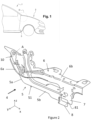
- a zone D delimited by the mixed line locates a possible installation zone on a vehicle 1, of a hinge of an opening 2, which is advantageously intended to protect other surrounding bodywork parts, such as a front wing 3, during an impact between the vehicle and an obstacle.
- the opening 2 is a hood for closing an engine compartment located in the front part of the vehicle, which is a body part laterally extended by right and left front wings. Only the right front wing 3 is shown in the figure 1 , knowing that by symmetry with respect to a median plane extending parallel to a longitudinal axis x to the vehicle, a right front wing is present.
- the hinge 4 of the opening is generally arranged in zone D, that is to say close to a rear zone of the engine hood 2.
- the motor vehicle preferably comprises two hinges 4 arranged in the zone D of the vehicle, each hinge 4 having the main function of ensuring the opening and closing of the engine compartment by moving the hood 2 upwards and downwards respectively.
- the hinge 4 comprises a hinge axis A around which the hood 2 is able to move in rotation.
- the hinge 4 has low impact resistance, particularly when these generate transverse forces relative to the vehicle. To thus prevent buckling of the hinge 4 of the hood articulation, which results in the lateral displacement of the engine hood that it supports, and consequently the degradation of the front wing, the hinge 4 is provided with means for retaining the lateral displacement of said engine hood.
- the hinge 4 comprises a fixed part also called a fixed knuckle, which is mounted securely to the body structure of the vehicle by means of a fixing support.
- the hinge 4 is positioned on the wing lining opposite the wing 3.
- This hinge 4 therefore comprises a fixed part, or fixed knuckle, 5 and a mobile part or mobile knuckle 6, pivotable relative to the fixed part along a pivot axis A.
- the fixed part 5 comprises a plate 51 extending mainly in the pivot plane of the hinge 4.
- the fixed part 5 comprises a distal part 5b extending along a first axis and a proximal part 5a extending along a second axis secant to the first axis.
- the proximal part or connecting part 5a comprises the axis A around which the movable part 6 of the hinge 4 is rotated.
- the connecting part 5b is of substantially vertical orientation in Z, once mounted, and comprises at its end, at the level of a vertex, an opening 10 forming a bearing for the rotation along the axis A of a rod of complementary shape belonging to said movable knuckle 6 while the orientation of the distal end of the fixed part is of substantially longitudinal orientation X (longitudinal axis of the vehicle).
- the rod of the movable part 6 extends transversely towards the outside of the vehicle.
- the rod is preferably arranged at a proximal part 6a of the movable part 6, at a peak.
- the opposite distal part 6b of the movable part 6, then located towards the front, is securely connected to the engine hood 2, by means of clamping screws for example.
- the opening 2 is composed of an ornamental part which is visible from the outside of the vehicle, which is also called the outer skin, and a rigid part also called the opening lining, the latter being linked to the movable part 6.
- a retaining element such as a tab 7 provided projecting from said movable knuckle 6 and extending in the pivot plane of said movable knuckle 6 relative to the fixed knuckle 5 and in the direction of said fixed knuckle 5.
- the tab 7 is thus arranged on the hinge 4 in such a way that it extends transversely from the movable part 6 towards the fixed part 5 when the hood 2 is in the engine compartment closed position.
- the end of the tab 7 is spaced from the distal part 5b so as not to prevent a collapse stroke (in Z) of the movable part 6 of the hinge for the pedestrian impact.
- the distal part 5b of the fixed part 5 comprises a retaining element 8 extending projecting from said fixed part 5 and forming a support surface against which the tab 7 of the movable part 6 must extend, in the closed position of the hinge 4.
- This stop element 8 is formed by the end of the plate 51 folded so as to extend in a direction perpendicular to the main axis of the distal part 5a then folded to extend again in an axis parallel to said main axis.
- the bearing face 81 of the retaining element 8 extends in an offset manner relative to the fixed part 5, which allows the positioning of the tab 6 opposite said bearing face 81 of the stop element 8.
- the tab 7 is spaced from the support face 81 of the stop element 8 by an interval of between 3 and 8 mm, preferably 3 mm.
- such a small interval limits any inertia of the engine cover 2 during an impact, which makes it possible to directly load the tab 7 while limiting the risks of dispersion of the impact forces.
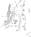
- the hinge 4 is such that once mounted on one side of a body, the retaining element 8 of the fixed part 5 is interposed between the retaining element 7 of the movable part 6 and the exterior side of the body. As a result, it is possible to mount the hinge 4 on a wing lining 11 on its face facing outwards and therefore opposite the wing 3.
- the retaining element 8 is thus located furthest to the outside and prevents the lateral movement of the engine hood towards the outside in the event of an impact by forming a stop for the retaining element 7 of the movable part 6 of the hinge.
- the fixed part 5 of the hinge 4 may have means for fixing to the wing lining, which are provided on the side of the fixed part 5 opposite that where the retaining element 8 is located.
- the fixing plate 51 further comprises a fixing part 52 comprising orifices for fixing the fixed part 5 to a hinge mounting bracket that serves as a mounting interface on the body (as seen in the figure 3 ).
- the articulation according to the invention makes it possible to obtain a good compromise between the pedestrian head impact and the repairable impact that cannot be obtained by stiffening the hinges. Indeed, the articulation hinge according to the invention leaves free the collapse of the hood and the hinges, essential for the pedestrian head impact.
Landscapes
- Engineering & Computer Science (AREA)
- Mechanical Engineering (AREA)
- Superstructure Of Vehicle (AREA)
Description
- La présente invention concerne une charnière pour un ouvrant de véhicule automobile comprenant une structure de caisse sur laquelle sont assemblées des organes de carrosserie, tel un ouvrant, ladite structure de caisse étant obtenue à partir d'un soubassement et au moins un côté d'habitacle assemblés ensemble, l'ouvrant étant monté articulé sur la structure de caisse au moyen de ladite au moins une charnière.
- Il est connu des charnières d'articulation comportant une partie fixe définissant un axe de rotation autour duquel un charnon mobile est apte à pivoter afin de déplacer un ouvrant tel qu'un capot de fermeture d'un compartiment moteur entre une position d'ouverture et une position de fermeture.
- Les charnières d'articulation d'un capot de fermeture d'un compartiment moteur sont bien souvent fabriquées à partir d'un matériau peu résistant à la déformation ce qui permet une mise en forme aisée et qui présente l'avantage d'être moins couteux.
- De telles charnières n'assurent pas un maintien suffisant du capot qu'elles relient à la structure de caisse du véhicule, lors d'un choc du véhicule avec un obstacle, ce qui engendre un démérite du véhicule par rapport à certaines normes règlementaires.
- En fait, il a été relevé que les charnières ne s'opposent pas suffisamment au déplacement en latéral du capot lors d'un choc, ce qui augmente d'autant le risque de déformation des pièces de carrosserie environnantes, telle qu'une aile latérale avant.
- En particulier, lors d'un choc de type choc réparabilité avant que l'on définit comme un choc à 16 km/h face à un mur rigide avec un angle de 10° avec 40% de recouvrement, le déplacement en latéral du capot (selon l'axe transversal Y du véhicule) vers l'extérieur dudit capot, provoque également la déformation de l'aile et donc entraîne un coût de réparation supplémentaire lié au remplacement ou à la réparation de l'aile.
- De manière à éviter ce débattement en Y, une possibilité consiste à rigidifier la partie mobile ou charnon mobile de la charnière. Toutefois, une telle rigidification entraîne une dégradation des performances choc tête-piéton dans la mesure où la course de déformation du charnon mobile entre le capot et les éléments du moteur est alors très restreinte. Le choc Réparabilité Avant 16 km/h face à un mur rigide de 10° avec 40% de recouvrement.
- On a proposé dans
FR 2 993 230 - Lorsque l'ouvrant qui est fixé sur la partie mobile de la charnière est en position fermée, la patte en saillie du charnon mobile s'étend le long de la face interne de la paroi du support de fixation, ainsi interposée entre la patte et un élément de structure sur lequel le support est fixé et, en cas de choc frontal contre un mur, le capot ou ouvrant qui tend à être entraîner en translation selon la direction Y du véhicule est empêché par la patte qui vient en appui contre la paroi du support de fixation de l'articulation, lui-même fixé sur un élément de structure de la caisse. Ainsi, lors d'un choc, la patte vient en butée contre la paroi du support de fixation interposée entre ladite patte et un élément de la caisse, ce qui renforce la retenue du capot et évite son déversement en Y.
- Un tel montage se retrouve dans le document
US20120186044A1 et dans le documentFR2929318A1 - Cette solution permet d'éviter le contact de la charnière avec l'aile droite (lors d'un choc à gauche) et ainsi de réduire les frais de réparation du véhicule lors d'un choc à 16 km/h (gain au niveau de la classe Réparabilité).
- Toutefois, si une telle charnière présente de nombreux avantages, dans certaines silhouettes de véhicules, le positionnement de la charnière est tel qu'il n'existe pas d'élément de structure en regard de cette charnière où pouvoir fixer le support de fixation de la charnière qui est alors fixé sur la doublure d'aile.
- De fait, lors d'un choc de type choc réparabilité avant que l'on définit comme un choc à 16 km/h face à un mur rigide avec un angle de 10° avec 40% de recouvrement, le déplacement en latéral du capot (selon l'axe transversal Y du véhicule) provoquerait alors la déformation de l'aile puisqu'au aucun élément de structure ne s'y oppose, ce qui entraîne un coût de réparation supplémentaire lié au remplacement ou à la réparation de l'aile.
- La présente invention a donc pour but de pallier cet inconvénient, en proposant une charnière d'articulation qui peut être montée directement en regard de d'une aile sans élément de structure interposé et qui, lors d'un choc de type choc réparabilité ne provoque pas de déversement latéral de l'ouvrant du type capot endommageant l'aile tout en respectant les contraintes liées au choc tête/piéton.
- A cet effet, l'invention concerne une charnière d'articulation selon la revendication 1.
- Ainsi, la charnière selon l'invention comprend des éléments de retenue en débattement d'un capot de moteur en cas de choc type réparabilité, agencés pour s'étendre en regard l'un de l'autre de sorte que, lorsque la charnière est montée sur un côté d'une caisse de véhicule, l'élément de retenue de la partie fixe est interposé entre l'élément de retenue de la partie mobile et le côté extérieur de caisse, donc par exemple l'aile de la caisse, s'opposant ainsi à un déversement latéral du capot vers l'aile selon l'axe Y du véhicule en suite d'un choc type choc réparabilité du côté opposé.
- En effet, lors du déversement du capot en Y, l'élément de retenue de la partie mobile vient en butée contre l'élément de retenue de la partie fixe ce qui permet de limiter voire éviter le déversement en Y et en particulier éviter l'endommagement de l'aile.
- Selon une forme de réalisation préférée de l'invention, la partie mobile de la charnière présente une forme dite en col de cygne, c'est-à-dire présentant au moins une portion courbe. La première courbe de la partie mobile correspond à une partie d'accrochage, à l'extrémité proximale de la partie fixe, montée à pivotement autour d'un axe de la partie fixe de la charnière tandis que l'extrémité distale de la partie mobile sur laquelle sera fixé le capot peut être rectiligne ou présenter une seconde courbe à courbure inverse.
- Selon l'invention, l'élément de retenue de la partie mobile est une patte anti-déversement qui s'étend en saillie radiale sur la partie distale de la partie mobile, par exemple à l'intérieur de la seconde courbe du côté opposé au capot, dans le plan de pivotement de ladite partie mobile par rapport à la partie fixe. La partie fixe présente un élément de butée tel qu'une patte de retenue ménagé sur sa partie distale de manière à s'étendre en regard de la patte anti-déversement de la partie mobile, dans un plan parallèle au plan de pivotement de la partie mobile par rapport à ladite partie fixe.
- Une telle charnière permet donc d'éviter le déversement en Y du capot en cas d'un choc dit de réparabilité mais en outre garantit une bonne performance en cas de choc tête piéton puisque la course de déformation de la partie mobile en col de cygne est suffisante.
- Selon l'invention, la patte de retenue de la partie fixe est constituée par l'extrémité de la partie distale de la partie fixe pliée de manière à s'étendre perpendiculairement par rapport à la partie fixe puis de nouveau parallèlement à celle-ci pour venir s'étendre en regard de la patte anti-déversement de telle sorte que, en position fermée de la charnière, la patte anti-déversement de la partie mobile s'étend contre ladite patte de retenue de sorte à venir en butée lors d'un déplacement latéral dit élément de retenue du côté et qu'en position de montage sur une caisse.
- Ainsi, lorsque la charnière est destinée à être fixée sur une doublure d'aile, la partie fixe peut comporter des moyens de fixation sur le support de fixation de la charnière qui sont ménagés à l'opposé de l'élément de butée, de sorte que le support de fixation de la charnière s'étend du côté opposé de la partie fixe par rapport à l'élément de butée, la patte de retenue étant ainsi entre la patte-anti-déversement et l'aile .
- Ainsi de manière avantageuse, la charnière selon cette forme particulière de l'invention permet d'empêcher en déversement latéral en Y du capot moteur même en l'absence d'élément de structure en regard de la charnière.
- Comme cité précédemment, la patte anti-déversement est réalisée d'une pièce avec la partie mobile ou charnon mobile afin de réduire le nombre de pièces mais également afin de faciliter l'assemblage du capot.
- De plus, une charnière selon l'invention peut être avantageusement utilisée uniquement du côté opposé au choc. L'ajout de masse est donc très faible.
- L'invention concerne une caisse de véhicule comportant au moins une charnière d'articulation d'un ouvrant tel qu'un capot moteur, telle que l'invention décrite précédemment, ladite charnière étant montée sur la caisse de sorte que l'élément de retenue de la partie fixe de la charnière est interposé entre l'élément de retenue de la partie mobile et le côté extérieur de la caisse constitué au moins de l'aile, de sorte qu'en cas de choc dit de réparabilité, l'élément de butée de la partie mobile bute contre l'élément de butée de la partie fixe ce qui prévient le déplacement latéral du capot vers le côté extérieur de la caisse.
- Ainsi, la charnière d'articulation selon l'invention peut être fixée sur une doublure d'aile, la charnière selon l'invention évitant un endommagement de l'aile en empêchant le débattement du capot.
- L'invention concerne aussi un véhicule automobile comportant un ouvrant tel qu'un capot de fermeture du compartiment moteur articulé sur la caisse du véhicule à l'aide de charnières d'articulation d'ouvrant dont au moins l'une est une charnière d'articulation selon l'invention.
- D'autres avantages et particularités de l'invention ressortent de la description de modes de réalisation faite ci-après en référence aux dessins annexés dans lesquels :
- la
figure 1 est une représentation schématique partielle d'un véhicule automobile vu de côté, comportant une charnière d'articulation d'un ouvrant, conforme à l'invention, - la
figure 2 est un vue en perspective latérale d'une charnière d'articulation selon l'invention en position fermée; - la
figure 3 est une vue en perspective latérale du côté opposé de la charnière de lafigure 2 ; - la
figure 4 est une vue en perspective latérale de la charnière montée sur une caisse ; et - la
figure 5 est une vue simplifiée de lafigure 4 . - En se reportant à la
figure 1 , une zone D délimitée par le trait mixte localise une zone d'implantation possible sur un véhicule 1, d'une charnière d'un ouvrant 2, qui est avantageusement destiné à protéger d'autres pièces environnantes de carrosserie, telle une aile 3 avant, lors d'un choc entre le véhicule et un obstacle. - L'ouvrant 2 est un capot de fermeture d'un compartiment moteur situé en partie avant du véhicule, qui est une pièce de carrosserie latéralement prolongée par des ailes avant droite et gauche. Seule l'aile 3 avant droite est représentée à la
figure 1 , sachant que par symétrie par rapport à un plan médian s'étendant parallèlement à un axe longitudinal x au véhicule, une aile avant droite est présente. - Dans ce qui suit, les termes « gauche », « droite », « avant » et « arrière » s'entendent selon un déplacement normal du véhicule. C'est de manière non limitative et dans un souci de clarté que, dans ce qui suit, seul l'un des côtés du véhicule est décrit, sachant bien entendu que par symétrie, l'autre côté du véhicule peut être concerné par le même détail technique.
- La charnière d'articulation 4 de l'ouvrant est de manière générale disposée dans la zone D, c'est-à-dire proche d'une zone arrière du capot moteur 2.
- Le véhicule automobile comprend de préférence deux charnières 4 disposées dans la zone D du véhicule, chaque charnière 4 ayant pour fonction principale d'assurer l'ouverture et la fermeture du compartiment moteur par le déplacement respectivement vers le haut et le bas du capot 2. Pour ce faire, la charnière 4 comprend un axe d'articulation A autour duquel est apte à se mouvoir en rotation le capot 2.
- De conception simple et peu coûteuse, la charnière 4 a une faible résistance au choc notamment lorsque ceux-ci génèrent des efforts transversaux par rapport au véhicule. Pour éviter ainsi le flambage de la charnière 4 d'articulation du capot, qui a pour conséquence le déplacement en latéral du capot moteur qu'elle supporte, et par voie de conséquence la dégradation de l'aile avant, la charnière 4 est pourvue de moyens de retenue au déplacement latéral dudit capot moteur.
- Selon l'illustration donnée en
figures 2 et3 , la charnière 4 comprend une partie fixe nommé aussi charnon fixe, qui est monté solidaire à la structure de caisse du véhicule au moyen d'un support de fixation. - Dans l'exemple représenté, la charnière 4 est positionnée sur la doublure d'aile en regard de l'aile 3. Cette charnière 4 comprend donc une partie fixe, ou charnon fixe, 5 et une partie mobile ou charnon mobile 6, entrainable en pivotement par rapport à la partie fixe selon un axe de pivotement A.
- La partie fixe 5 comprend une platine 51 s'étendant principalement dans le plan de pivotement de la charnière 4. La partie fixe 5 comprend une partie distale 5b s'étendant selon un premier axe et une partie proximale 5a s'étendant selon un second axe sécant au premier axe. La partie proximale ou partie de liaison 5a comporte l'axe A autour duquel est entraînée en rotation la partie mobile 6 de la charnière 4.
- La partie de liaison 5b est d'orientation sensiblement verticale en Z, une fois montée, et comprend à son extrémité, au niveau d'un sommet, une ouverture 10 formant un palier pour la rotation selon l'axe A d'une tige de forme complémentaire appartenant audit charnon mobile 6 tandis que l'orientation de l'extrémité distale de la partie fixe est d'orientation sensiblement longitudinal X (axe longitudinald u véhiucle).
- La tige de la partie mobile 6 s'étend transversalement vers l'extérieur du véhicule. La tige est de préférence disposée à une partie proximale 6a de la partie mobile 6, au niveau d'un sommet. La partie opposée distale 6b de la partie mobile 6, située alors vers l'avant, est liée de manière solidaire au capot 2 moteur, au moyen de vis de serrage par exemple.
- L'ouvrant 2 est composé d'une partie ornementale qui est visible de l'extérieur du véhicule, que l'on nomme aussi peau extérieure, et d'une partie rigide nommée aussi doublure d'ouvrant, cette dernière étant liée à la partie mobile 6.
- La partie mobile 6 présente de préférence une forme en col de cygne c'est-à-dire présentant au moins une courbe. Ainsi, la partie proximale 6a de la partie mobile 6 est pourvue de la tige lui permettant d'être montée à pivotement sur la partie fixe 5. Cette partie proximale 6a s'étend le long de la partie proximale de liaison 5b puis forme une première courbe en s'écartant de la partie distale 5a de la partie fixe avant de s'étendre de manière linaire, de sorte que la partie distale 6b de la partie mobile 6 s'étend sensiblement au-dessus et parallèlement à la partie distale 5a. Cette partie distale de la partie mobile 6 présente des moyens de fixation du capot 2.
- Au niveau de cette partie distale 6b de la partie mobile 6 est prévu un élément de retenue tel qu'une patte 7 ménagée en saillie dudit charnon mobile 6 et s'étendant dans le plan de pivotement dudit charnon mobile 6 par rapport au charnon fixe 5 et en direction dudit charnon fixe 5.
- De préférence, cette patte 7 s'étend sensiblement radialement à la partie distale 6c de la partie mobile 6. Cette patte 7 forme ainsi une butée qui s'étend en saillie du charnon mobile 6 dans le plan de pivotement de la charnière 4.
- La patte 7 est ainsi disposée sur la charnière 4 de telle manière qu'elle s'étend transversalement depuis la partie mobile 6 vers la partie fixe 5 lorsque le capot 2 est en position de fermeture du compartiment moteur.
- Toutefois l'extrémité de la patte 7 est écartée de la partie distale 5b de sorte à ne pas empêcher une course d'affaissement (en Z) de la partie mobile 6 de la charnière pour le choc piéton.
- La patte 7 est réalisée d'une pièce avec la partie mobile 6 par exemple par moulage, emboutissage.
- La partie distale 5b de la partie fixe 5 comporte un élément de retenue 8 s'étendant en saillie de ladite partie fixe 5 et formant une surface d'appui contre laquelle doit s'étendre la patte 7 de la partie mobile 6, en position fermée de la charnière 4.
- Cet élément de butée 8 est formé par l'extrémité de la platine 51 pliée de manière à s'étendre selon une direction perpendiculaire à l'axe principal de la partie distale 5a puis repliée pour s'étendre de nouveau selon un axe parallèle audit axe principal. La face d'appui 81 de l'élément de retenue 8 s'étend en décroché par rapport à la partie fixe 5, ce qui autorise le positionnement de la patte 6 en regard de ladite face d'appui 81 de l'élément de butée 8.
- Compte tenu des jeux et affleurement qu'il convient de respecter dans l'assemblage des pièces de carrosserie du véhicule, la patte 7 est écartée de la face d'appui 81 de l'élément de butée 8 d'un intervalle compris entre 3 et 8 mm, de préférence 3 mm.
- Avantageusement, un intervalle aussi faible limite toute inertie du capot moteur 2 lors d'un choc, ce qui permet de charger directement la patte 7 tout en limitant les risques de dispersion des efforts du choc.
- La charnière 4 est telle qu'une fois montée sur un côté d'une caisse, l'élément de retenue 8 de la partie fixe 5 est interposé entre l'élément de retenue 7 de la partie mobile 6 et le côté de extérieur de la caisse. De ce fait, on peut prévoir de monter la charnière 4 sur une doublure d'aile 11 sur sa face tournée vers l'extérieur et donc en regard de l'aile 3. L'élément de retenue 8 se trouve ainsi le plus à l'extérieur et empêche le débattement latéral du capot moteur vers l'extérieur en cas de choc en formant butée pour l'élément de retenue 7 de la partie mobile 6 de la charnière.
- De ce fait, la partie fixe 5 de la charnière 4 peut présenter des moyens de fixation sur la doublure d'aile, qui sont ménagés du côté de la partie fixe 5 opposé à celui où se trouve à l'élément de retenue 8. Ainsi, la platine de fixation 51 comporte en outre une partie 52 de fixation comportant des orifices pour fixer la partie fixe 5 sur un support de fixation de charnière qui sert d'interface de montage sur la caisse (comme cela est visible à la
figure 3 ). - L'articulation selon l'invention permet d'obtenir un bon compromis entre le choc piéton tête et le choc réparabilité qu'on ne peut obtenir en rigidifiant les charnières. En effet, la charnière d'articulation selon l'invention laisse libre l'affaissement du capot et des charnières, indispensable pour le choc piéton tête.
Claims (5)
- Charnière d'articulation (4) d'un ouvrant du type capot (2) de fermeture du compartiment moteur sur une caisse de véhicule automobile, ladite charnière (4) comportant une partie fixe (5) et une partie mobile (6), la partie mobile (6) étant montée entraînable en rotation autour d'un axe de pivotement (A) de la partie fixe (5) entre une position d'ouverture et une position de fermeture de la charnière (4), la partie mobile (6) présentant un élément de retenue (7) s'étendant en saillie de ladite partie mobile (6) vers la partie fixe (5) dans le plan de pivotement de ladite charnière (4), la partie fixe (5) comprenant un élément de retenue (8) complémentaire le long duquel l'élément de retenue (6) de la partie mobile s'étendant en position fermée de la charnière (4), l'élément de retenue de la partie mobile (6) étant une patte (7) qui s'étend en saillie radiale sur une partie distale (6b) de la partie mobile (6) dans le plan de pivotement de ladite partie mobile (6) par rapport à la partie fixe (7), l'élément de retenue (8) de la partie fixe (5) étant une patte de retenue ménagé sur sa partie distale, de manière à s'étendre en regard de la patte (7) de la partie mobile (6), dans un plan parallèle au plan de pivotement de la partie mobile (6) par rapport à ladite partie fixe (5), caractérisée en ce que la patte de retenue (8) de la partie fixe (5) est constituée par l'extrémité de sa partie distale (5b) pliée de manière à s'étendre perpendiculairement par rapport à la partie fixe (5) puis de nouveau parallèlement à celle-ci.
- Charnière (4) selon la revendication 1, caractérisée en ce que les éléments de retenue (7, 8) sont agencés pour s'étendre en regard l'un de l'autre de sorte que, lorsque la charnière est montée sur un côté d'une caisse de véhicule, l'élément de retenue (8) de la partie fixe (5) est interposé entre l'élément de retenue (7) de la partie mobile (6) et le côté extérieur de la caisse.
- Caisse de véhicule comportant au moins une charnière (4) d'articulation d'un ouvrant tel qu'un capot moteur (2), montée sur un côté de la caisse, selon l'une des revendications 1 ou 2, caractérisée en ce que l'élément de retenue (8) de la partie fixe (5) de la charnière (4) est interposé entre l'élément de retenue (7) de la partie mobile (6) et le côté extérieur de la caisse.
- Caisse selon la revendication 3, caractérisée en ce que la charnière d'articulation est fixée sur une doublure d'aile en regard de l'aile.
- Véhicule automobile comportant un ouvrant tel qu'un capot de fermeture du compartiment moteur articulé sur la caisse du véhicule à l'aide de charnières d'articulation d'ouvrant dont au moins l'une est une charnière d'articulation selon l'une des revendications 1 ou 2.
Applications Claiming Priority (2)
| Application Number | Priority Date | Filing Date | Title |
|---|---|---|---|
| FR1751524A FR3063301B1 (fr) | 2017-02-24 | 2017-02-24 | Charniere d'articulation d'un ouvrant du type capot de fermeture du compartiment moteur sur une caisse de vehicule automobile |
| PCT/FR2018/050155 WO2018154203A1 (fr) | 2017-02-24 | 2018-01-23 | Charnière d'articulation d'un ouvrant du type capot de fermeture du compartiment moteur sur une caisse de véhicule automobile. |
Publications (2)
| Publication Number | Publication Date |
|---|---|
| EP3585966A1 EP3585966A1 (fr) | 2020-01-01 |
| EP3585966B1 true EP3585966B1 (fr) | 2025-03-05 |
Family
ID=58670007
Family Applications (1)
| Application Number | Title | Priority Date | Filing Date |
|---|---|---|---|
| EP18703071.3A Active EP3585966B1 (fr) | 2017-02-24 | 2018-01-23 | Charnière d'articulation d'un ouvrant du type capot de fermeture du compartiment moteur sur une caisse de véhicule automobile. |
Country Status (4)
| Country | Link |
|---|---|
| EP (1) | EP3585966B1 (fr) |
| CN (1) | CN110382807B (fr) |
| FR (1) | FR3063301B1 (fr) |
| WO (1) | WO2018154203A1 (fr) |
Families Citing this family (2)
| Publication number | Priority date | Publication date | Assignee | Title |
|---|---|---|---|---|
| DE102019100977B4 (de) * | 2018-03-15 | 2020-08-20 | Bayerische Motoren Werke Aktiengesellschaft | Kraftfahrzeug |
| CN115009376B (zh) * | 2022-06-28 | 2023-12-05 | 浙江吉利控股集团有限公司 | 一种发动机盖铰链加强板及车辆 |
Family Cites Families (6)
| Publication number | Priority date | Publication date | Assignee | Title |
|---|---|---|---|---|
| FR2929318B1 (fr) * | 2008-03-28 | 2010-03-19 | Peugeot Citroen Automobiles Sa | Dispositif de retenue d'un ouvrant et vehicule comportant un tel dispositif |
| CN201784702U (zh) * | 2010-08-13 | 2011-04-06 | 浙江吉利汽车研究院有限公司 | 汽车发动机罩铰链结构 |
| FR2965005B1 (fr) * | 2010-09-17 | 2012-09-07 | Peugeot Citroen Automobiles Sa | Charniere d'articulation d'un capot de vehicule automobile |
| US8579061B2 (en) * | 2011-01-21 | 2013-11-12 | Chrysler Group Llc | Vehicle compartment cover coupling |
| FR2993230B1 (fr) * | 2012-07-13 | 2014-07-11 | Peugeot Citroen Automobiles Sa | Charniere d'articulation d'un ouvrant du type capot de fermeture du compartiment moteur sur une caisse de vehicule automobile |
| DE102013018079A1 (de) * | 2013-11-27 | 2015-05-28 | GM Global Technology Operations LLC (n. d. Gesetzen des Staates Delaware) | Scharnier für ein Kraftfahrzeug |
-
2017
- 2017-02-24 FR FR1751524A patent/FR3063301B1/fr active Active
-
2018
- 2018-01-23 EP EP18703071.3A patent/EP3585966B1/fr active Active
- 2018-01-23 CN CN201880014099.7A patent/CN110382807B/zh not_active Expired - Fee Related
- 2018-01-23 WO PCT/FR2018/050155 patent/WO2018154203A1/fr not_active Ceased
Also Published As
| Publication number | Publication date |
|---|---|
| CN110382807B (zh) | 2021-09-28 |
| WO2018154203A1 (fr) | 2018-08-30 |
| FR3063301A1 (fr) | 2018-08-31 |
| CN110382807A (zh) | 2019-10-25 |
| EP3585966A1 (fr) | 2020-01-01 |
| FR3063301B1 (fr) | 2019-11-08 |
Similar Documents
| Publication | Publication Date | Title |
|---|---|---|
| EP2186686B1 (fr) | Dispositif de déplacement d'un élément rigide, et véhicule équipé d'un tel dispositif | |
| EP2042388B1 (fr) | Dispositif de protection des piétons et véhicule muni d'un tel dispositif | |
| EP2027000A1 (fr) | Dispositif de fixation d'un balai d'essuie-glace sur un bras | |
| EP2382364B1 (fr) | Systeme d'articulation d'un capot de vehicule automobile et capot associe | |
| FR3063301B1 (fr) | Charniere d'articulation d'un ouvrant du type capot de fermeture du compartiment moteur sur une caisse de vehicule automobile | |
| EP1048521B1 (fr) | Dispositif de montage d'un bloc optique sur des éléments de carrosserie d'un véhicule automobile | |
| EP2872718B1 (fr) | Charnière d'articulation d'un ouvrant du type capot de fermeture du compartiment moteur sur une caisse de véhicule automobile | |
| EP2782780A1 (fr) | Ensemble d'un projecteur et son dispositif de montage limitant les reparations de l'aile adjacente lors d'un choc et vehicule correspondant | |
| FR2929318A1 (fr) | Dispositif de retenue d'un ouvrant et vehicule comportant un tel dispositif | |
| WO2010081949A1 (fr) | Support de charnon mobile amortisseur de choc pieton | |
| FR3041307A1 (fr) | Organe d’essuie-glace comprenant un capot articule | |
| EP0828050B1 (fr) | Charnière de porte, notamment pour véhicule automobile | |
| EP4739867A1 (fr) | Système d'articulation pour capot de véhicule automobile | |
| FR2802570A1 (fr) | Dispositif de protection pour ouvrant de vehicule automobile | |
| FR3125788A1 (fr) | Véhicule automobile avec au moins une pièce de guidage en déplacement du capot en cas de choc frontal. | |
| FR2888275A1 (fr) | Dispositif de centrage d'une porte coulissante, notamment pour vehicule automobile. | |
| FR2816978A1 (fr) | Systeme de guidage pour ouvrant de vehicule automobile | |
| EP3078527A1 (fr) | Dispositif de detrompage pour le montage correct d'une biellette anti-couple non symetrique dans le berceau d'un vehicule | |
| FR3097584A1 (fr) | Charnière de capot de véhicule automobile anti-basculement et procédé de montage du capot | |
| WO2020135960A1 (fr) | Adaptateur pour balai d'essuie-glace de vehicule automobile | |
| FR2667987A1 (fr) | Antenne telescopique escamotable pour vehicule automobile. | |
| EP0555146A1 (fr) | Essuie-glace, muni d'un capuchon, notamment pour véhicule automobile | |
| FR2880378A1 (fr) | Charniere de porte avant pour vehicule automobile | |
| WO2022175417A1 (fr) | Système de connexion d'un balai d'essuyage sur un bras d'un système d'essuyage | |
| FR3144940A1 (fr) | Volet arrière de coffre doté d’un becquet « flottant » |
Legal Events
| Date | Code | Title | Description |
|---|---|---|---|
| STAA | Information on the status of an ep patent application or granted ep patent |
Free format text: STATUS: UNKNOWN |
|
| STAA | Information on the status of an ep patent application or granted ep patent |
Free format text: STATUS: THE INTERNATIONAL PUBLICATION HAS BEEN MADE |
|
| PUAI | Public reference made under article 153(3) epc to a published international application that has entered the european phase |
Free format text: ORIGINAL CODE: 0009012 |
|
| STAA | Information on the status of an ep patent application or granted ep patent |
Free format text: STATUS: REQUEST FOR EXAMINATION WAS MADE |
|
| 17P | Request for examination filed |
Effective date: 20190705 |
|
| AK | Designated contracting states |
Kind code of ref document: A1 Designated state(s): AL AT BE BG CH CY CZ DE DK EE ES FI FR GB GR HR HU IE IS IT LI LT LU LV MC MK MT NL NO PL PT RO RS SE SI SK SM TR |
|
| AX | Request for extension of the european patent |
Extension state: BA ME |
|
| DAV | Request for validation of the european patent (deleted) | ||
| DAX | Request for extension of the european patent (deleted) | ||
| RAP1 | Party data changed (applicant data changed or rights of an application transferred) |
Owner name: PSA AUTOMOBILES SA |
|
| STAA | Information on the status of an ep patent application or granted ep patent |
Free format text: STATUS: EXAMINATION IS IN PROGRESS |
|
| 17Q | First examination report despatched |
Effective date: 20230925 |
|
| RAP3 | Party data changed (applicant data changed or rights of an application transferred) |
Owner name: STELLANTIS AUTO SAS |
|
| GRAP | Despatch of communication of intention to grant a patent |
Free format text: ORIGINAL CODE: EPIDOSNIGR1 |
|
| STAA | Information on the status of an ep patent application or granted ep patent |
Free format text: STATUS: GRANT OF PATENT IS INTENDED |
|
| INTG | Intention to grant announced |
Effective date: 20241028 |
|
| GRAS | Grant fee paid |
Free format text: ORIGINAL CODE: EPIDOSNIGR3 |
|
| GRAA | (expected) grant |
Free format text: ORIGINAL CODE: 0009210 |
|
| STAA | Information on the status of an ep patent application or granted ep patent |
Free format text: STATUS: THE PATENT HAS BEEN GRANTED |
|
| AK | Designated contracting states |
Kind code of ref document: B1 Designated state(s): AL AT BE BG CH CY CZ DE DK EE ES FI FR GB GR HR HU IE IS IT LI LT LU LV MC MK MT NL NO PL PT RO RS SE SI SK SM TR |
|
| REG | Reference to a national code |
Ref country code: GB Ref legal event code: FG4D Free format text: NOT ENGLISH |
|
| REG | Reference to a national code |
Ref country code: CH Ref legal event code: EP |
|
| REG | Reference to a national code |
Ref country code: DE Ref legal event code: R084 Ref document number: 602018079779 Country of ref document: DE Ref country code: IE Ref legal event code: FG4D Free format text: LANGUAGE OF EP DOCUMENT: FRENCH |
|
| REG | Reference to a national code |
Ref country code: DE Ref legal event code: R096 Ref document number: 602018079779 Country of ref document: DE |
|
| PG25 | Lapsed in a contracting state [announced via postgrant information from national office to epo] |
Ref country code: RS Free format text: LAPSE BECAUSE OF FAILURE TO SUBMIT A TRANSLATION OF THE DESCRIPTION OR TO PAY THE FEE WITHIN THE PRESCRIBED TIME-LIMIT Effective date: 20250605 |
|
| PG25 | Lapsed in a contracting state [announced via postgrant information from national office to epo] |
Ref country code: FI Free format text: LAPSE BECAUSE OF FAILURE TO SUBMIT A TRANSLATION OF THE DESCRIPTION OR TO PAY THE FEE WITHIN THE PRESCRIBED TIME-LIMIT Effective date: 20250305 |
|
| REG | Reference to a national code |
Ref country code: NL Ref legal event code: MP Effective date: 20250305 |
|
| PG25 | Lapsed in a contracting state [announced via postgrant information from national office to epo] |
Ref country code: ES Free format text: LAPSE BECAUSE OF FAILURE TO SUBMIT A TRANSLATION OF THE DESCRIPTION OR TO PAY THE FEE WITHIN THE PRESCRIBED TIME-LIMIT Effective date: 20250305 |
|
| REG | Reference to a national code |
Ref country code: LT Ref legal event code: MG9D |
|
| PG25 | Lapsed in a contracting state [announced via postgrant information from national office to epo] |
Ref country code: NO Free format text: LAPSE BECAUSE OF FAILURE TO SUBMIT A TRANSLATION OF THE DESCRIPTION OR TO PAY THE FEE WITHIN THE PRESCRIBED TIME-LIMIT Effective date: 20250605 |
|
| PG25 | Lapsed in a contracting state [announced via postgrant information from national office to epo] |
Ref country code: HR Free format text: LAPSE BECAUSE OF FAILURE TO SUBMIT A TRANSLATION OF THE DESCRIPTION OR TO PAY THE FEE WITHIN THE PRESCRIBED TIME-LIMIT Effective date: 20250305 |
|
| PG25 | Lapsed in a contracting state [announced via postgrant information from national office to epo] |
Ref country code: LV Free format text: LAPSE BECAUSE OF FAILURE TO SUBMIT A TRANSLATION OF THE DESCRIPTION OR TO PAY THE FEE WITHIN THE PRESCRIBED TIME-LIMIT Effective date: 20250305 |
|
| PG25 | Lapsed in a contracting state [announced via postgrant information from national office to epo] |
Ref country code: GR Free format text: LAPSE BECAUSE OF FAILURE TO SUBMIT A TRANSLATION OF THE DESCRIPTION OR TO PAY THE FEE WITHIN THE PRESCRIBED TIME-LIMIT Effective date: 20250606 Ref country code: BG Free format text: LAPSE BECAUSE OF FAILURE TO SUBMIT A TRANSLATION OF THE DESCRIPTION OR TO PAY THE FEE WITHIN THE PRESCRIBED TIME-LIMIT Effective date: 20250305 |
|
| REG | Reference to a national code |
Ref country code: AT Ref legal event code: MK05 Ref document number: 1773067 Country of ref document: AT Kind code of ref document: T Effective date: 20250305 |
|
| PG25 | Lapsed in a contracting state [announced via postgrant information from national office to epo] |
Ref country code: NL Free format text: LAPSE BECAUSE OF FAILURE TO SUBMIT A TRANSLATION OF THE DESCRIPTION OR TO PAY THE FEE WITHIN THE PRESCRIBED TIME-LIMIT Effective date: 20250305 |
|
| PG25 | Lapsed in a contracting state [announced via postgrant information from national office to epo] |
Ref country code: SE Free format text: LAPSE BECAUSE OF FAILURE TO SUBMIT A TRANSLATION OF THE DESCRIPTION OR TO PAY THE FEE WITHIN THE PRESCRIBED TIME-LIMIT Effective date: 20250305 |
|
| PG25 | Lapsed in a contracting state [announced via postgrant information from national office to epo] |
Ref country code: SM Free format text: LAPSE BECAUSE OF FAILURE TO SUBMIT A TRANSLATION OF THE DESCRIPTION OR TO PAY THE FEE WITHIN THE PRESCRIBED TIME-LIMIT Effective date: 20250305 |
|
| PG25 | Lapsed in a contracting state [announced via postgrant information from national office to epo] |
Ref country code: PT Free format text: LAPSE BECAUSE OF FAILURE TO SUBMIT A TRANSLATION OF THE DESCRIPTION OR TO PAY THE FEE WITHIN THE PRESCRIBED TIME-LIMIT Effective date: 20250707 |
|
| PG25 | Lapsed in a contracting state [announced via postgrant information from national office to epo] |
Ref country code: PL Free format text: LAPSE BECAUSE OF FAILURE TO SUBMIT A TRANSLATION OF THE DESCRIPTION OR TO PAY THE FEE WITHIN THE PRESCRIBED TIME-LIMIT Effective date: 20250305 Ref country code: IT Free format text: LAPSE BECAUSE OF FAILURE TO SUBMIT A TRANSLATION OF THE DESCRIPTION OR TO PAY THE FEE WITHIN THE PRESCRIBED TIME-LIMIT Effective date: 20250305 |
|
| PG25 | Lapsed in a contracting state [announced via postgrant information from national office to epo] |
Ref country code: AT Free format text: LAPSE BECAUSE OF FAILURE TO SUBMIT A TRANSLATION OF THE DESCRIPTION OR TO PAY THE FEE WITHIN THE PRESCRIBED TIME-LIMIT Effective date: 20250305 |
|
| PG25 | Lapsed in a contracting state [announced via postgrant information from national office to epo] |
Ref country code: CZ Free format text: LAPSE BECAUSE OF FAILURE TO SUBMIT A TRANSLATION OF THE DESCRIPTION OR TO PAY THE FEE WITHIN THE PRESCRIBED TIME-LIMIT Effective date: 20250305 Ref country code: EE Free format text: LAPSE BECAUSE OF FAILURE TO SUBMIT A TRANSLATION OF THE DESCRIPTION OR TO PAY THE FEE WITHIN THE PRESCRIBED TIME-LIMIT Effective date: 20250305 |
|
| PG25 | Lapsed in a contracting state [announced via postgrant information from national office to epo] |
Ref country code: RO Free format text: LAPSE BECAUSE OF FAILURE TO SUBMIT A TRANSLATION OF THE DESCRIPTION OR TO PAY THE FEE WITHIN THE PRESCRIBED TIME-LIMIT Effective date: 20250305 |
|
| PG25 | Lapsed in a contracting state [announced via postgrant information from national office to epo] |
Ref country code: SK Free format text: LAPSE BECAUSE OF FAILURE TO SUBMIT A TRANSLATION OF THE DESCRIPTION OR TO PAY THE FEE WITHIN THE PRESCRIBED TIME-LIMIT Effective date: 20250305 |
|
| PG25 | Lapsed in a contracting state [announced via postgrant information from national office to epo] |
Ref country code: IS Free format text: LAPSE BECAUSE OF FAILURE TO SUBMIT A TRANSLATION OF THE DESCRIPTION OR TO PAY THE FEE WITHIN THE PRESCRIBED TIME-LIMIT Effective date: 20250705 |
|
| REG | Reference to a national code |
Ref country code: DE Ref legal event code: R097 Ref document number: 602018079779 Country of ref document: DE |
|
| PLBE | No opposition filed within time limit |
Free format text: ORIGINAL CODE: 0009261 |
|
| STAA | Information on the status of an ep patent application or granted ep patent |
Free format text: STATUS: NO OPPOSITION FILED WITHIN TIME LIMIT |
|
| PG25 | Lapsed in a contracting state [announced via postgrant information from national office to epo] |
Ref country code: DK Free format text: LAPSE BECAUSE OF FAILURE TO SUBMIT A TRANSLATION OF THE DESCRIPTION OR TO PAY THE FEE WITHIN THE PRESCRIBED TIME-LIMIT Effective date: 20250305 |
|
| REG | Reference to a national code |
Ref country code: CH Ref legal event code: L10 Free format text: ST27 STATUS EVENT CODE: U-0-0-L10-L00 (AS PROVIDED BY THE NATIONAL OFFICE) Effective date: 20260114 |
|
| PGFP | Annual fee paid to national office [announced via postgrant information from national office to epo] |
Ref country code: FR Payment date: 20251217 Year of fee payment: 9 |
|
| 26N | No opposition filed |
Effective date: 20251208 |
|
| PGFP | Annual fee paid to national office [announced via postgrant information from national office to epo] |
Ref country code: DE Payment date: 20251217 Year of fee payment: 9 |