EP3585745B1 - Wärmebehandelbarer beschichteter artikel mit ir-reflektierenden schichten auf titannitrid- und ito-basis - Google Patents
Wärmebehandelbarer beschichteter artikel mit ir-reflektierenden schichten auf titannitrid- und ito-basis Download PDFInfo
- Publication number
- EP3585745B1 EP3585745B1 EP18708833.1A EP18708833A EP3585745B1 EP 3585745 B1 EP3585745 B1 EP 3585745B1 EP 18708833 A EP18708833 A EP 18708833A EP 3585745 B1 EP3585745 B1 EP 3585745B1
- Authority
- EP
- European Patent Office
- Prior art keywords
- coated article
- reflecting layer
- layer
- glass substrate
- nitride
- Prior art date
- Legal status (The legal status is an assumption and is not a legal conclusion. Google has not performed a legal analysis and makes no representation as to the accuracy of the status listed.)
- Active
Links
Images
Classifications
-
- C—CHEMISTRY; METALLURGY
- C03—GLASS; MINERAL OR SLAG WOOL
- C03C—CHEMICAL COMPOSITION OF GLASSES, GLAZES OR VITREOUS ENAMELS; SURFACE TREATMENT OF GLASS; SURFACE TREATMENT OF FIBRES OR FILAMENTS MADE FROM GLASS, MINERALS OR SLAGS; JOINING GLASS TO GLASS OR OTHER MATERIALS
- C03C17/00—Surface treatment of glass, not in the form of fibres or filaments, by coating
- C03C17/001—General methods for coating; Devices therefor
- C03C17/002—General methods for coating; Devices therefor for flat glass, e.g. float glass
-
- C—CHEMISTRY; METALLURGY
- C03—GLASS; MINERAL OR SLAG WOOL
- C03C—CHEMICAL COMPOSITION OF GLASSES, GLAZES OR VITREOUS ENAMELS; SURFACE TREATMENT OF GLASS; SURFACE TREATMENT OF FIBRES OR FILAMENTS MADE FROM GLASS, MINERALS OR SLAGS; JOINING GLASS TO GLASS OR OTHER MATERIALS
- C03C17/00—Surface treatment of glass, not in the form of fibres or filaments, by coating
- C03C17/34—Surface treatment of glass, not in the form of fibres or filaments, by coating with at least two coatings having different compositions
- C03C17/3411—Surface treatment of glass, not in the form of fibres or filaments, by coating with at least two coatings having different compositions with at least two coatings of inorganic materials
- C03C17/3429—Surface treatment of glass, not in the form of fibres or filaments, by coating with at least two coatings having different compositions with at least two coatings of inorganic materials at least one of the coatings being a non-oxide coating
- C03C17/3435—Surface treatment of glass, not in the form of fibres or filaments, by coating with at least two coatings having different compositions with at least two coatings of inorganic materials at least one of the coatings being a non-oxide coating comprising a nitride, oxynitride, boronitride or carbonitride
-
- C—CHEMISTRY; METALLURGY
- C03—GLASS; MINERAL OR SLAG WOOL
- C03C—CHEMICAL COMPOSITION OF GLASSES, GLAZES OR VITREOUS ENAMELS; SURFACE TREATMENT OF GLASS; SURFACE TREATMENT OF FIBRES OR FILAMENTS MADE FROM GLASS, MINERALS OR SLAGS; JOINING GLASS TO GLASS OR OTHER MATERIALS
- C03C17/00—Surface treatment of glass, not in the form of fibres or filaments, by coating
- C03C17/34—Surface treatment of glass, not in the form of fibres or filaments, by coating with at least two coatings having different compositions
- C03C17/3411—Surface treatment of glass, not in the form of fibres or filaments, by coating with at least two coatings having different compositions with at least two coatings of inorganic materials
- C03C17/3429—Surface treatment of glass, not in the form of fibres or filaments, by coating with at least two coatings having different compositions with at least two coatings of inorganic materials at least one of the coatings being a non-oxide coating
- C03C17/3482—Surface treatment of glass, not in the form of fibres or filaments, by coating with at least two coatings having different compositions with at least two coatings of inorganic materials at least one of the coatings being a non-oxide coating comprising silicon, hydrogenated silicon or a silicide
-
- C—CHEMISTRY; METALLURGY
- C03—GLASS; MINERAL OR SLAG WOOL
- C03C—CHEMICAL COMPOSITION OF GLASSES, GLAZES OR VITREOUS ENAMELS; SURFACE TREATMENT OF GLASS; SURFACE TREATMENT OF FIBRES OR FILAMENTS MADE FROM GLASS, MINERALS OR SLAGS; JOINING GLASS TO GLASS OR OTHER MATERIALS
- C03C17/00—Surface treatment of glass, not in the form of fibres or filaments, by coating
- C03C17/34—Surface treatment of glass, not in the form of fibres or filaments, by coating with at least two coatings having different compositions
- C03C17/36—Surface treatment of glass, not in the form of fibres or filaments, by coating with at least two coatings having different compositions at least one coating being a metal
- C03C17/3602—Surface treatment of glass, not in the form of fibres or filaments, by coating with at least two coatings having different compositions at least one coating being a metal the metal being present as a layer
- C03C17/3657—Surface treatment of glass, not in the form of fibres or filaments, by coating with at least two coatings having different compositions at least one coating being a metal the metal being present as a layer the multilayer coating having optical properties
- C03C17/366—Low-emissivity or solar control coatings
-
- C—CHEMISTRY; METALLURGY
- C23—COATING METALLIC MATERIAL; COATING MATERIAL WITH METALLIC MATERIAL; CHEMICAL SURFACE TREATMENT; DIFFUSION TREATMENT OF METALLIC MATERIAL; COATING BY VACUUM EVAPORATION, BY SPUTTERING, BY ION IMPLANTATION OR BY CHEMICAL VAPOUR DEPOSITION, IN GENERAL; INHIBITING CORROSION OF METALLIC MATERIAL OR INCRUSTATION IN GENERAL
- C23C—COATING METALLIC MATERIAL; COATING MATERIAL WITH METALLIC MATERIAL; SURFACE TREATMENT OF METALLIC MATERIAL BY DIFFUSION INTO THE SURFACE, BY CHEMICAL CONVERSION OR SUBSTITUTION; COATING BY VACUUM EVAPORATION, BY SPUTTERING, BY ION IMPLANTATION OR BY CHEMICAL VAPOUR DEPOSITION, IN GENERAL
- C23C14/00—Coating by vacuum evaporation, by sputtering or by ion implantation of the coating forming material
- C23C14/06—Coating by vacuum evaporation, by sputtering or by ion implantation of the coating forming material characterised by the coating material
- C23C14/0641—Nitrides
- C23C14/0652—Silicon nitride
-
- C—CHEMISTRY; METALLURGY
- C23—COATING METALLIC MATERIAL; COATING MATERIAL WITH METALLIC MATERIAL; CHEMICAL SURFACE TREATMENT; DIFFUSION TREATMENT OF METALLIC MATERIAL; COATING BY VACUUM EVAPORATION, BY SPUTTERING, BY ION IMPLANTATION OR BY CHEMICAL VAPOUR DEPOSITION, IN GENERAL; INHIBITING CORROSION OF METALLIC MATERIAL OR INCRUSTATION IN GENERAL
- C23C—COATING METALLIC MATERIAL; COATING MATERIAL WITH METALLIC MATERIAL; SURFACE TREATMENT OF METALLIC MATERIAL BY DIFFUSION INTO THE SURFACE, BY CHEMICAL CONVERSION OR SUBSTITUTION; COATING BY VACUUM EVAPORATION, BY SPUTTERING, BY ION IMPLANTATION OR BY CHEMICAL VAPOUR DEPOSITION, IN GENERAL
- C23C14/00—Coating by vacuum evaporation, by sputtering or by ion implantation of the coating forming material
- C23C14/06—Coating by vacuum evaporation, by sputtering or by ion implantation of the coating forming material characterised by the coating material
- C23C14/08—Oxides
- C23C14/086—Oxides of zinc, germanium, cadmium, indium, tin, thallium or bismuth
-
- C—CHEMISTRY; METALLURGY
- C23—COATING METALLIC MATERIAL; COATING MATERIAL WITH METALLIC MATERIAL; CHEMICAL SURFACE TREATMENT; DIFFUSION TREATMENT OF METALLIC MATERIAL; COATING BY VACUUM EVAPORATION, BY SPUTTERING, BY ION IMPLANTATION OR BY CHEMICAL VAPOUR DEPOSITION, IN GENERAL; INHIBITING CORROSION OF METALLIC MATERIAL OR INCRUSTATION IN GENERAL
- C23C—COATING METALLIC MATERIAL; COATING MATERIAL WITH METALLIC MATERIAL; SURFACE TREATMENT OF METALLIC MATERIAL BY DIFFUSION INTO THE SURFACE, BY CHEMICAL CONVERSION OR SUBSTITUTION; COATING BY VACUUM EVAPORATION, BY SPUTTERING, BY ION IMPLANTATION OR BY CHEMICAL VAPOUR DEPOSITION, IN GENERAL
- C23C14/00—Coating by vacuum evaporation, by sputtering or by ion implantation of the coating forming material
- C23C14/22—Coating by vacuum evaporation, by sputtering or by ion implantation of the coating forming material characterised by the process of coating
- C23C14/34—Sputtering
-
- E—FIXED CONSTRUCTIONS
- E06—DOORS, WINDOWS, SHUTTERS, OR ROLLER BLINDS IN GENERAL; LADDERS
- E06B—FIXED OR MOVABLE CLOSURES FOR OPENINGS IN BUILDINGS, VEHICLES, FENCES OR LIKE ENCLOSURES IN GENERAL, e.g. DOORS, WINDOWS, BLINDS, GATES
- E06B9/00—Screening or protective devices for wall or similar openings, with or without operating or securing mechanisms; Closures of similar construction
- E06B9/24—Screens or other constructions affording protection against light, especially against sunshine; Similar screens for privacy or appearance; Slat blinds
-
- G—PHYSICS
- G02—OPTICS
- G02B—OPTICAL ELEMENTS, SYSTEMS OR APPARATUS
- G02B5/00—Optical elements other than lenses
- G02B5/20—Filters
- G02B5/208—Filters for use with infrared or ultraviolet radiation, e.g. for separating visible light from infrared and/or ultraviolet radiation
-
- G—PHYSICS
- G02—OPTICS
- G02B—OPTICAL ELEMENTS, SYSTEMS OR APPARATUS
- G02B5/00—Optical elements other than lenses
- G02B5/20—Filters
- G02B5/28—Interference filters
- G02B5/281—Interference filters designed for the infrared light
- G02B5/282—Interference filters designed for the infrared light reflecting for infrared and transparent for visible light, e.g. heat reflectors, laser protection
-
- C—CHEMISTRY; METALLURGY
- C03—GLASS; MINERAL OR SLAG WOOL
- C03C—CHEMICAL COMPOSITION OF GLASSES, GLAZES OR VITREOUS ENAMELS; SURFACE TREATMENT OF GLASS; SURFACE TREATMENT OF FIBRES OR FILAMENTS MADE FROM GLASS, MINERALS OR SLAGS; JOINING GLASS TO GLASS OR OTHER MATERIALS
- C03C2217/00—Coatings on glass
- C03C2217/90—Other aspects of coatings
- C03C2217/94—Transparent conductive oxide layers [TCO] being part of a multilayer coating
- C03C2217/948—Layers comprising indium tin oxide [ITO]
-
- C—CHEMISTRY; METALLURGY
- C03—GLASS; MINERAL OR SLAG WOOL
- C03C—CHEMICAL COMPOSITION OF GLASSES, GLAZES OR VITREOUS ENAMELS; SURFACE TREATMENT OF GLASS; SURFACE TREATMENT OF FIBRES OR FILAMENTS MADE FROM GLASS, MINERALS OR SLAGS; JOINING GLASS TO GLASS OR OTHER MATERIALS
- C03C2218/00—Methods for coating glass
- C03C2218/10—Deposition methods
- C03C2218/15—Deposition methods from the vapour phase
- C03C2218/154—Deposition methods from the vapour phase by sputtering
-
- E—FIXED CONSTRUCTIONS
- E06—DOORS, WINDOWS, SHUTTERS, OR ROLLER BLINDS IN GENERAL; LADDERS
- E06B—FIXED OR MOVABLE CLOSURES FOR OPENINGS IN BUILDINGS, VEHICLES, FENCES OR LIKE ENCLOSURES IN GENERAL, e.g. DOORS, WINDOWS, BLINDS, GATES
- E06B9/00—Screening or protective devices for wall or similar openings, with or without operating or securing mechanisms; Closures of similar construction
- E06B9/24—Screens or other constructions affording protection against light, especially against sunshine; Similar screens for privacy or appearance; Slat blinds
- E06B2009/2417—Light path control; means to control reflection
Definitions
- This invention relates to a coated article according to claim 1 and to a method according to claim 16.
- Low solar factor (SF) and solar heat gain coefficient (SHGC) values are desired in some applications, particularly in warm weather climates.
- Solar factor (SF) calculated in accordance with EN standard 410, relates to a ratio between the total energy entering a room or the like through a glazing and the incident solar energy.
- a low SF value is indicative of a coated article (e.g., IG window unit) that is capable of keeping a room fairly cool in summertime months during hot ambient conditions.
- LSG High light-to-solar gain (LSG) values are also desirable. LSG is calculated as T vis /SHGC.
- SF G-Factor; EN410-673 2011
- SHGC NFRC-2001
- Silver based low-E (low emissivity) coatings for windows are known in the art.
- the silver is not particularly durable, and can be easily corroded if exposed to moisture for instance.
- silver based low-E coatings are not desirable for monolithic applications such as monolithic windows, and are typically used in IG window units including multiple glass panes, because of the durability problems of silver based low-E coatings.
- Solar control coatings are known in the art.
- solar control coatings having a layer stack of glass/Si 3 N 4 /NiCr/Si 3 N 4 /NiCr/Si 3 N 4 are known in the art, where the NiCr layer may be nitrided.
- U.S. Patent Document 2012/0177899 While layer stacks of U.S. Patent Document 2012/0177899 provide reasonable solar control and are overall good coatings, they are lacking in certain respects.
- the glass side reflective a* values (a* under R G Y) in Examples 1, 4 and 5 in paragraphs 0025-0026 of US '899 are -17.8, - 15.95, and +2.22, respectively, and the glass side visible reflectance values (R G Y) in Examples 1 and 4 are 36% and 36.87%, respectively.
- Examples 1 and 4 in US '899 are undesirable because the glass side visible reflectance (R G Y) values are too high at 36% and 36.87%, respectively, and because the glass side reflective a* values are too negative at -17.8 and -15.95, respectively.
- R G Y is reduced down to 15.82% in Example 5
- the coatings described in US '899 were not able to achieve a combination of acceptable visible reflectivity values and glass side reflective a* coloration values.
- Certain known solar control coatings use NbN, NbZr, or NbZrN as IR reflecting layers. For instance, see U.S. Patent Document 2012/0177899 and U.S. Patent No. 8,286,395 . However, the instant inventors have surprisingly found that solar control coatings that use solely these materials NbN, NbZr, or NbZrN for IR reflecting layers are lacking in terms of normal emissivity (E n ) for a given IR reflecting layer(s) thickness.
- E n normal emissivity
- Document US 2016/002100 A1 discloses a pane with thermal radiation reflecting coating, comprising a substrate and at least one thermal radiation reflecting coating on at least one of the surfaces of the substrate, wherein the coating, proceeding from the substrate, comprises at least one lower dielectric layer, one functional layer that contains at least one transparent, electrically conductive oxide, and one upper dielectric layer, and wherein at least one darkening layer is arranged below the lower dielectric layer, between the lower dielectric layer and the functional layer, between the functional layer and the upper dielectric layer, and/or above the upper dielectric layer, and wherein the darkening layer contains at least one metal, one metal nitride, and/or one metal carbide with a melting point greater than 1900° C.
- Document WO 2015/197969 A1 discloses a glazing unit comprising a glass substrate provided on a first face, which is intended to form the face of said glazing unit in its use position, with a thin-film multilayer comprising, from said substrate, a transparent electrically conductive oxide film, a first dielectric film, a film based on niobium nitride, then a second dielectric film.
- Document WO 2017/160326 A1 discloses coated articles that include two or more infrared (IR) reflecting layers (e.g., of or including NbZr, Nb, NiCr, NiCrMo, and/or a nitride thereof) sandwiched between at least dielectric layers, and/or a method of making the same.
- the coating may be designed so that the coated articles realize bronze glass side reflective coloration in combination with a low solar factor (SF) and/or a low solar heat gain coefficient (SFIGC).
- Such coated articles may be used in the context of monolithic windows, insulating glass (IG) window units, laminated windows, and/or other suitable applications, and may optionally be heat treated (e.g., thermally tempered) in certain instances.
- a coating prefferably be designed so as to have a combination of acceptable visible transmission (TY or T vis ), desirable glass side reflective coloration (e.g., desirable a* and/or b* reflective color values), desirably low film side visible reflectance, low emittance/emissivity, low SHGC, and high LSG for a coated article in window applications.
- acceptable visible transmission TY or T vis
- desirable glass side reflective coloration e.g., desirable a* and/or b* reflective color values
- desirably low film side visible reflectance, low emittance/emissivity, low SHGC, and high LSG for a coated article in window applications.
- the applications such as monolithic window applications desire glass side reflective coloration that is not significantly red.
- the applications such as monolithic window applications desire glass side reflective a* color values that are either negative or no greater than +1.6 or +1.0 (glass side reflective a* values higher than +1.6 are undesirably red).
- Such reflective a* values are especially desirable for example in the context of glass side reflective (R G[or outside, or exterior] Y) a* values.
- the embodiments of this invention relate to coated articles that include two or more functional infrared (IR) reflecting layers that may be sandwiched between at least transparent dielectric layers, and a method of making the same.
- the dielectric layers are of or include silicon nitride
- the first infrared (IR) reflecting layer is of or includes indium-tin-oxide (ITO) and the second infrared (IR) reflecting layer is of or includes titanium nitride (e.g., TiN).
- the use of these different materials for the different IR reflecting layers surprisingly results in improved optics such as improved glass side reflective a* values and/or high LSG values which are often desirable characteristics in window applications, and desirably low film side visible reflectance, and the provision of the first IR reflecting layer of or including ITO allows coated articles to be more easily tailored for desired visible transmission values while the second IR reflecting layer of or including TiN can keep the normal emissivity, SF and/or SHGC values reasonably low.
- Coating according to embodiments of this invention may be designed so that before and/or after any optional heat treatment such as thermal tempering the coated articles realize one or more of: desirable glass side reflective visible coloration that is not too red (e.g., reflective a* color value(s) from -8 to +1.6); a desirably low solar heat gain coefficient (SHGC); desirable visible transmission (TY or T vis ); desirably low film side visible reflectance; thermal stability upon optional heat treatment (HT) such as thermal tempering; desirably low normal emissivity/emittance (E n ); and/or desirably high light-to-solar gain ratio (LSG).
- SHGC may be as high as 80% for uncoated glass. The higher the LSG value, the greater the energy saving.
- Such coated articles may be used in the context of monolithic windows, insulating glass (IG) window units, laminated windows, and/or other suitable applications.
- a coated article including a coating supported by a glass substrate, the coating comprising: a first infrared (IR) reflecting layer comprising ITO on the glass substrate; a first dielectric layer comprising silicon nitride on the glass substrate over at least the first IR reflecting layer comprising ITO; a second layer IR reflecting layer comprising a nitride of titanium on the glass substrate over at least the first dielectric layer comprising silicon nitride, so that the first dielectric layer comprising silicon nitride is located between at least the first IR reflecting layer comprising ITO and the second IR reflecting layer comprising the nitride of titanium; a second dielectric layer comprising silicon nitride on the glass substrate over at least the second IR reflecting layer comprising the nitride of titanium; wherein the coating contains no IR reflecting layer based on silver; wherein the first IR reflecting layer comprising ITO is from 250-450 Angstroms thick; and wherein the coating has a normal emittance
- a coated article including a coating supported by a glass substrate, the coating comprising: a first infrared (IR) reflecting layer comprising ITO on the glass substrate; a first dielectric layer comprising silicon nitride on the glass substrate over at least the first IR reflecting layer comprising ITO; a second layer IR reflecting layer comprising a nitride of titanium on the glass substrate over at least the first dielectric layer comprising silicon nitride, so that the first dielectric layer comprising silicon nitride is located between at least the first IR reflecting layer comprising ITO and the second IR reflecting layer comprising the nitride of titanium; a second dielectric layer comprising silicon nitride on the glass substrate over at least the second IR reflecting layer comprising the nitride of titanium; wherein the coating contains no IR reflecting layer based on silver; wherein the coating has a normal emittance (E n ) value of no greater than 0.30; and wherein the coated article has:
- a coated article including a coating supported by a glass substrate, the coating comprising: a first infrared (IR) reflecting layer comprising ITO on the glass substrate; a first dielectric layer on the glass substrate over and directly contacting the first IR reflecting layer comprising ITO; a second layer IR reflecting layer comprising a metal nitride on the glass substrate over and directly contacting the first dielectric layer, so that the first dielectric layer is located between and directly contacting the first IR reflecting layer comprising ITO and the second IR reflecting layer comprising the metal nitride; a second dielectric layer on the glass substrate over and directly contacting the second IR reflecting layer comprising the metal nitride; wherein the coating contains no IR reflecting layer based on silver; and wherein the coated article has a visible transmission from about 15-80%.
- the metal nitride may be a nitride of titanium, zirconium, niobium, or the like. In certain examples, one
- this invention covers monolithic window units, IG window units, laminated window units, and any other article including a glass substrate having a coating thereon as claimed.
- monolithic measurements may be taken by removing a coated substrate from an IG window unit and/or laminated window unit, and then performing monolithic measurements. It is also noted that for a given coating the SF and SHGC values will be significantly higher for a monolithic window unit than for an IG window unit with the same coated article.
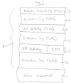
- Fig. 1 is a partial cross sectional view of a monolithic coated article (heat treated or not heat treated) according to an example embodiment of this invention.
- a coating 8 is designed so as to have a combination of acceptable visible transmission (TY or T vis ), desirable glass side reflective coloration (e.g., desirable a* and b* reflective color values), low film side visible reflectance, low SHGC, and high LSG for a coated article for use in window applications or the like.
- acceptable visible transmission TY or T vis
- desirable glass side reflective coloration e.g., desirable a* and b* reflective color values
- low film side visible reflectance e.g., low film side visible reflectance
- low SHGC high LSG
- Example applications include architectural windows, residential windows, monolithic windows, automotive windows, and/or IG windows.
- Certain embodiments of this invention relate to coated articles having a coating 8 on a glass substrate 1, where the coating includes two or more functional infrared (IR) reflecting layers 3 and 5 which may be sandwiched between at least transparent dielectric layers 2, 4, 6, 7, and/or a method of making the same.
- Some of the transparent dielectric layers, such as dielectric layer(s) 2 and/or 7, are optional and need not be provided in certain example embodiments.
- the dielectric layers 2, 4 and 6 are preferably amorphous, preferably have a k ⁇ 0.1, and may be of or include silicon nitride, silicon oxynitride, zinc stannate, tin oxide, or the like.
- Transparent dielectric overcoat 7, of or including zirconium oxide or any other suitable material, is optional.
- At least one of the IR reflecting layers is of or including titanium nitride (e.g., TiN) and at least another of the IR reflecting layers is of or including ITO.
- upper IR reflecting layer 5 is of or including titanium nitride (e.g., TiN) and lower IR reflecting layer 3 is of or including ITO.
- Coating 8 may be designed so that before and/or after any optional heat treatment such as thermal tempering the coated articles realize one or more of: desirable glass side reflective visible coloration that is not too red (e.g., reflective a* color value(s) from -8 to +1.6); a desirably low solar heat gain coefficient (SHGC); desirable visible transmission (TY or T vis ); low film side reflectance; thermal stability upon optional heat treatment (HT) such as thermal tempering; desirably low E n ; and/or a desirably high light-to-solar gain ratio (LSG).
- the coating 8 contains no IR reflecting layer based on Ag or Au.
- the applications such as monolithic window applications desire glass side reflective coloration that is not significantly red.
- the applications such as monolithic window applications desire glass side reflective a* color values that are either negative or no greater than +1.6 (glass side reflective a* values higher than +1.6 are undesirably red).
- Such glass side reflective a* values are not too red and are desirable in the context of glass side reflective (R G Y) a* values.
- Coated articles may optionally be heat treated in certain example embodiments of this invention, and are preferably designed to be heat treatable.
- the terms "heat treatment” and “heat treating” as used herein mean heating the article to a temperature sufficient to achieve thermal tempering, heat bending, and/or heat strengthening of the glass inclusive article.
- This definition includes, for example, heating a coated article in an oven or furnace at a temperature of least about 580 degrees C, more preferably at least about 600 degrees C, for a sufficient period to allow tempering, bending, and/or heat strengthening.
- the HT may be for at least about 4 or 5 minutes.
- the coated article may or may not be heat treated in different embodiments of this invention. Instead of HT at >600C (e.g., tempering), this coating can also achieve desired performance by activating HT at as low as 350 degrees C for example. After HT at 350 C for example, the glass is not tempered and may be cut to desired size.
- Figure 1 is a cross sectional view of a coated article according to an example embodiment of this invention.
- the solar control coating 8 includes two IR reflecting layers 3 and 5, and transparent dielectric layers 2, 4, 6 and 7.
- the coated article includes at least glass substrate 1 (e.g., clear, green, bronze, grey, blue, or blue-green glass substrate from about 1.0 to 12.0 mm thick, more preferably from 4-8 mm thick, with an example glass substrate thickness being 6 mm), transparent dielectric layers 2, 4, 6 (e.g., of or including silicon nitride [e.g., Si 3 N 4 ], silicon oxynitride, silicon zirconium nitride, or some other suitable dielectric), and IR reflecting layers 3, 5.
- glass substrate 1 e.g., clear, green, bronze, grey, blue, or blue-green glass substrate from about 1.0 to 12.0 mm thick, more preferably from 4-8 mm thick, with an example glass substrate thickness being 6 mm
- transparent dielectric layers 2, 4, 6 e.g.,
- Upper IR reflecting layer 5 is of or including titanium nitride (e.g., TiN, preferably a stoichiometric or substantially stoichiometric type) and lower IR reflecting layer 3 is of or including conductive ITO.
- the upper IR reflecting layer 5 is of or includes TiN x in certain example embodiments of this invention, where x is preferably from 0.8 to 1.2, more preferably from 0.9 to 1.1, with an example value being about 1.0. These "x" values provide for improved/lowered emittance values compared to if "x" is too low for instance.
- the titanium nitride has been found to be very durable compared to silver for example, and more resistant to moisture induced corrosion compared to silver for example.
- IR reflecting layer 5 may include some small amount of oxygen in certain instances, it is preferable that layer 5 is substantially free of oxygen such as no more than 8% oxygen, more preferably no more than about 5% oxygen, and most preferably no more than about 3% or 2% oxygen in certain embodiments (atomic %).
- IR reflecting layer 5 is of or including titanium nitride in preferred embodiments of this invention
- upper IR reflecting layer 5 may be of another metal nitride such as zirconium nitride and/or niobium nitride in alternative embodiments of this invention.
- the coated article may optionally include transparent dielectric overcoat layer 7 of or including a protective material such as zirconium oxide (e.g., ZrO 2 ) or silicon oxynitride.
- a dielectric layer of or including silicon oxynitride and/or zirconium silicon oxynitride of any suitable stoichiometry may be located between and contacting layers 6 and 7 in the upper part of the layer stack in certain example embodiments.
- coating 8 does not include any metallic IR blocking or reflecting layer of or based on Ag or Au.
- IR reflecting layers 3 and 5 reflect at least some IR radiation, and do not contact any other metal or metal based IR reflecting layer.
- each of the layers it is possible for each of the layers to include other materials such as dopants. It will be appreciated of course that other layers may also be provided, or certain layers may be omitted, and different materials may be used, in certain alternative embodiments of this invention. For example, another metal nitride layer 5 could be added above the ITO in certain alternative embodiments of this invention.
- the overall coating 8 of Fig. 1 includes at least the illustrated layers in certain example embodiments, with layers 2 and 7 in particular being optional.
- the terms "oxide” and "nitride” as used herein include various stoichiometries.
- silicon nitride (for one or more of layers 2, 4, 6) includes stoichiometric Si 3 N 4 , as well as non-stoichiometric silicon nitride, and these layers may be doped with other material(s) such as Al and/or O.
- the illustrated layers may be deposited on glass substrate 1 via magnetron sputtering, any other type of sputtering, or via any other suitable technique in different embodiments of this invention.
- ⁇ layer(s) may be provided in the stack shown in Fig. 1 such as between layers 2 and 3, or between layers 3 and 4, or between the substrate 1 and layer 2, or the like. Generally, other layer(s) may also be provided in other locations of the coating. Thus, while the coating 8 or layers thereof is/are “on” or “supported by” substrate 1 (directly or indirectly), other layer(s) may be provided therebetween. Thus, for example, the layer system 8 and layers thereof shown in Fig. 1 are considered “on” the substrate 1 even when other layer(s) may be provided therebetween (i.e., the terms “on” and “supported by” as used herein are not limited to directly contacting). However, there may be the direct contacts shown in Fig. 1 in preferred embodiments.
- dielectric layers 2, 4, and 6 may each have an index of refraction "n" of from 1.7 to 2.5 (at 550 nm), more preferably from 1.8 to 2.2 in certain embodiments, and most preferably from about 2.0 to 2.06 in preferred embodiments of this invention.
- n index of refraction
- One, two, three, or all of these layers 2, 4, 6 may be of or include silicon nitride and/or silicon oxynitride in certain example embodiments of this invention.
- layers 2, 4, 6 comprise silicon nitride (e.g., Si 3 N 4 ) or silicon oxynitride
- sputtering targets including Si employed to form these layers may or may not be admixed with up to 1-20% (e.g., 8%) by weight aluminum or stainless steel (e.g. SS#316), with about this amount then appearing in the layers so formed. Even with this amount(s) of aluminum and/or stainless steel, such layers are still considered dielectric layers.
- each of the IR reflecting layers 3 and 5 is provided between respective nitride layers (e.g., silicon nitride based layers 2, 4, 6) in order to reduce or prevent damage to the IR reflecting layers during possible heat treatment (e.g., thermal tempering, heat bending, and/or heat strengthening) thereby permitting predictable coloration to be achieved following the heat treatment at multiple viewing angles.
- nitride layers e.g., silicon nitride based layers 2, 4, 6
- possible heat treatment e.g., thermal tempering, heat bending, and/or heat strengthening
- IG insulating glass
- example thicknesses in angstroms
- materials for the respective layers of the Fig. 1 embodiment on the glass substrate 1 are as follows in certain example embodiments for achieving desired transmission, glass side reflective coloration, and visible reflectance in combination with a desirably low SHGC value(s) and/or a desirably high LSG value (layers are listed in order moving away from the glass substrate 1): Table 1 (Thicknesses in Fig. 1 embodiment), wherein the Example Range is not according to the present invention.
- IR reflector e.g., ITO
- layer 3 100-1,000 ⁇ 250-450 ⁇ 330 ⁇ silicon nitride
- layer 4 20-1100 ⁇ 25-400 ⁇ 300 ⁇ IR reflector (e.g., TiN) (layer 5): 50-450 ⁇ 130-300 ⁇ 200 ⁇
- Table 1 above relates to, for example, embodiments where coating 8 is designed so that before and/or after any optional heat treatment such as thermal tempering the coated articles realize one, two, three, four, five, six or all seven of: desirable glass side reflective visible coloration such as not too red reflective color (e.g., reflective a* color value(s) from -8 to +1.6); a desirably low SHGC; desirable visible transmission; low film side visible reflectance, thermal stability upon optional HT such as thermal tempering; desirably low E n ; and/or a desirably high LSG.
- lower IR reflecting layer 3 may be physically thicker than upper IR reflecting layer 5 by at least 50 angstroms ( ⁇ ), more preferably by at least 100 ⁇ .
- upper dielectric layer 6 is physically thicker than center dielectric layer 4 by at least 50 angstroms ( ⁇ ), more preferably by at least 100 ⁇ , and sometimes by at least 150 ⁇ .
- coated articles according to the Fig. 1 embodiment have color/optical characteristics as follows in Table 2 (measured monolithically). It is noted that subscript “G” stands for glass side reflective, subscript “T” stands for transmissive, and subscript “F” stands for film side reflective. As is known in the art, glass side (G) means when viewed from the glass side (as opposed to the layer/film side) of the coated article. Film side (F) means when viewed from the side of the coated article on which the coating is provided.
- Table 2 The characteristics below in Table 2 are in accordance with Illuminant C, 2 degree Observer, and are applicable to HT and non-HT coated articles herein.
- Glass side reflective coloration may be such that coated articles appear neutral colored, blue-green colored, or yellow-green colored in various example embodiments of this invention.
- Table 2 Color/Optical Characteristics (Fig. 1 embodiment monolithic) General Preferred Most Preferred T vis (TY): 15-80% 20-70% 30-60% (or 40-60%) a* T -10 to +5 -8 to +2 -6 to 0 b* T - -15 to +7 -10 to +3 -9 to 0 R G Y(glass side): ⁇ 30% ⁇ 25% ⁇ 20% a* G -10 to +1.6 -8 to +1.6 -6 to +1 b* G -25 to +9 -9 to +4 -8 to +1 R F Y(film side): ⁇ 10% ⁇ 8% ⁇ 5% a* F -9 to +9 -6 to +7 -3 to +5 b* F -14 to +9 -9 to +4 -8 to 0 E n : ⁇ 0.30 ⁇ 0.25 ⁇ 0.22 SH
- Example 1 representing an example embodiments of this invention, as well we Comparative Examples (CE) 1-5, are set forth below.
- Comparative Examples (CEs) 1-4 and Examples 1-2 were sputter-deposited (as all examples) layer stacks modeled on 4 mm thick clear glass substrates. And CE 5 was a layer stacks modeled on 4 mm thick green glass substrate.
- the optical measurements are monolithic measurements.
- Optical data for CEs 1-5 and Examples 1-2 is in accordance with Illuminant C, 2 degree Observer.
- the silicon nitride layers were doped with about 8% Al.
- the TiN layers were approximately stoichiometric. Layer thicknesses are in angstroms ( ⁇ ).
- "L" in Table 4 below stand for Layer (e.g., L2 means layer 2 shown in Fig. 1 , L3 means layer 3 shown in Fig. 1 , and so forth).
- CEs Measured monolithically after thermal tempering (HT), the CEs had the following characteristics.
- Table 4 Measured Monolithic Optical Data (CEs 1-5) Parameter CE 1 CE 2 CE 3 CE4 CE5 T vis (TY)(transmission ): 18.6% 24.2% 35.3% 23.1% 21.8% L* T : 50.2 56.3 66.0 55.2 53.8 a* T -7.2 -7.0 -5.5 -3.15 -5.86 b* T -4.3 -1.5 -0.8 -8.27 -7.97 R G Y(glass side refl.
- Examples 1-2 according to examples of this invention had the following layer stack. Layer thicknesses are in angstroms ( ⁇ ). Table 5: Layer Stack of Examples 1-2 Example L3(ITO) L4(Si 3 N 4 ) L5(TiN) L6(Si 3 N 4 ) L7(Si 3 N 4 ) Ex. 1: 330 300 200 450 n/a Ex. 2: 330 20 180 350 40
- Example 2 T vis (TY)(transmission ): 51.97% 54.4% a* T -3.14 -3.2 b* T -2.81 -3.9 R G Y(glass side refl. %): 19.9% 16.0% a* G : -4.0 -2.1 b* G : -0.9 0.0 R F Y(film side refl. %): 2.2% 2.6% a* F : +3.35 +5.6 b* F : -4.71 +1.8 E n : 0.20 0.22 SHGC (NFRC-2001): 0.41 0.42 LSG: 1.25 1.30
- CEs 2 and 3 were more acceptable, but still low, at 1.01 and 1.14, these CEs 2 and 3 along with the other CEs had undesirably high film side reflectance of 10.8% or higher.
- CE3 had an undesirably high normal emittance/emissivity (E n ) of 0.36, which means that insufficient IR is blocked by the coating.
- E n normal emittance/emissivity
- No comparative example (CE) has a sufficiently low normal emittance/emissivity (E n ) combined with desirably low film side visible reflectance and desirably high LSG.
- ITO for layer 3 in Example 1 unexpectedly reduced the film side visible reflectance vales to more acceptable and aesthetically pleasing 2.2% and 2.6% and surprisingly increased the LSG value to 1.25 and 1.30 which means a significant energy saving.
- TiN for layer 5 and ITO for layer 3 allowed normal emittance (E n ) to remain in an acceptable range of no greater than 0.30, more preferably no greater than 0.25, and most preferably no greater than 0.22.
- a coated article including a coating supported by a glass substrate, the coating comprising: a first infrared (IR) reflecting layer comprising ITO on the glass substrate; a first dielectric layer comprising silicon nitride on the glass substrate over at least the first IR reflecting layer comprising ITO; a second layer IR reflecting layer comprising a nitride of titanium on the glass substrate over at least the first dielectric layer comprising silicon nitride, so that the first dielectric layer comprising silicon nitride is located between at least the first IR reflecting layer comprising ITO and the second IR reflecting layer comprising the nitride of titanium; a second dielectric layer comprising silicon nitride on the glass substrate over at least the second IR reflecting layer comprising the nitride of titanium; wherein the coating contains no IR reflecting layer based on silver; wherein the first IR reflecting layer comprising ITO is from 250-450 Angstroms thick; and wherein the coating has a normal emittance
- the coating in some instances contains only two IR reflecting layers.
- the first dielectric layer comprising silicon nitride may be located between and directly contacting the first and second IR reflecting layers.
- the second IR reflecting layer comprising the nitride of titanium may comprise TiN x , where x is from 0.8 to 1.2, more preferably from 0.9 to 1.1.
- the second IR reflecting layer may contain from 0-8% oxygen (atomic %), more preferably from 0-5% oxygen (atomic %).
- the coating may further comprise another dielectric layer comprising silicon nitride or silicon oxynitride located between and contacting the glass substrate and the first IR reflecting layer.
- the second IR reflecting layer may consist essentially of the nitride of titanium.
- the coating may further comprise an overcoat comprising an oxide of zirconium.
- the coated article may have a visible transmission from about 20-70% and/or a light-to-solar gain ratio (LSG) of at least 1.15.
- LSG light-to-solar gain ratio
- the coated article may have a light-to-solar gain ratio (LSG) of at least 1.22.
- LSG light-to-solar gain ratio
- the coated article may have a film side visible reflectance no greater than 8%, more preferably no greater than 5%.
- the glass substrate may be a clear glass substrate.
- the coated article may have a glass side reflective a* value of from -8 to +1.0, and/or a film side reflective a* value of from -9 to +9.
- one or more of the dielectric layers comprising silicon nitride may further comprise oxygen and/or may be doped with aluminum.
- the coated article may be a monolithic window.
- the coated article measured monolithically may have an SHGC value of no greater than 0.52, more preferably no greater than 0.45, and most preferably no greater than 0.42.
- the first IR reflecting layer comprising ITO may be from 100-1,000 ⁇ thick, and/or the second IR reflecting layer comprising the nitride of titanium may be from 50-450 ⁇ thick.
- the first IR reflecting layer comprising ITO is from 250-450 ⁇ thick
- the second IR reflecting layer comprising the nitride of titanium may be from 130-300 ⁇ thick.
Landscapes
- Chemical & Material Sciences (AREA)
- Engineering & Computer Science (AREA)
- Materials Engineering (AREA)
- Chemical Kinetics & Catalysis (AREA)
- Organic Chemistry (AREA)
- General Chemical & Material Sciences (AREA)
- Geochemistry & Mineralogy (AREA)
- Life Sciences & Earth Sciences (AREA)
- Mechanical Engineering (AREA)
- Metallurgy (AREA)
- Physics & Mathematics (AREA)
- Structural Engineering (AREA)
- General Physics & Mathematics (AREA)
- Optics & Photonics (AREA)
- Civil Engineering (AREA)
- Toxicology (AREA)
- Health & Medical Sciences (AREA)
- Architecture (AREA)
- Surface Treatment Of Glass (AREA)
- Laminated Bodies (AREA)
- Optical Elements Other Than Lenses (AREA)
- Physical Vapour Deposition (AREA)
Claims (16)
- Beschichteter Artikel, der eine Beschichtung beinhaltet, die von einem Glassubstrat getragen wird, wobei die Beschichtung umfasst:- eine erste Infrarot- (IR-) reflektierende Schicht, die ITO umfasst, auf dem Glassubstrat;- eine erste dielektrische Schicht, die Siliziumnitrid umfasst, auf dem Glassubstrat über zumindest der ersten IR-reflektierenden Schicht, die ITO umfasst;- eine zweite Schicht IR-reflektierende Schicht, die ein Nitrid von Titan umfasst, auf dem Glassubstrat über zumindest der ersten dielektrischen Schicht, die Siliziumnitrid umfasst, sodass sich die erste dielektrische Schicht, die Siliziumnitrid umfasst, zwischen zumindest der ersten IR-reflektierenden Schicht, die ITO umfasst, und der zweiten IR-reflektierenden Schicht, die das Nitrid von Titan umfasst, befindet;- eine zweite dielektrische Schicht, die Siliziumnitrid umfasst, auf dem Glassubstrat über zumindest der zweiten IR-reflektierenden Schicht, die das Nitrid von Titan umfasst;wobei die Beschichtung keine IR-reflektierende Schicht auf Silberbasis enthält;wobei die erste IR-reflektierende Schicht, die ITO umfasst, 250-450 Å dick ist; undwobei die Beschichtung einen normalen Emittanz- (E n) Wert von nicht größer als 0,30 aufweist; undwobei der beschichtete Artikel, monolithisch gemessen, aufweist: eine Transmission im Sichtbaren von 15-80 %, eine filmseitige Reflexion im Sichtbaren von nicht größer als 10 %, eine glasseitige Reflexion im Sichtbaren von nicht größer als 30 %, einen Reflexionswert a* auf der Glasseite von -10,0 bis +1,6, und ein Licht-zu-Solar-Verstärkungsverhältnis (LSG) von zumindest 1,10.
- Beschichteter Artikel nach Anspruch 1, wobei die Beschichtung weiter eine andere dielektrische Schicht umfasst, die Siliziumnitrid umfasst, die sich zwischen dem Glassubstrat und der ersten IR-reflektierenden Schicht befindet und diese kontaktiert.
- Beschichteter Artikel nach Anspruch 2, wobei die andere dielektrische Schicht, die Siliziumnitrid umfasst, weiter Sauerstoff umfasst.
- Beschichteter Artikel nach einem vorstehenden Anspruch, wobei das Glassubstrat ein Klarglassubstrat ist und/oder wobei der beschichtete Artikel ein monolithisches Fenster ist.
- Beschichteter Artikel nach einem vorstehenden Anspruch, wobei der beschichtete Artikel eine Transmission im Sichtbaren von 20-70 % aufweist.
- Beschichteter Artikel nach einem vorstehenden Anspruch, wobei die Beschichtung nur zwei IR-reflektierende Schichten enthält und/oder wobei die erste dielektrische Schicht, die Siliziumnitrid umfasst, sich zwischen der ersten und der zweiten IR-reflektierenden Schicht befindet und diese direkt kontaktiert.
- Beschichteter Artikel nach einem vorstehenden Anspruch, wobei die zweite IR-reflektierende Schicht, die das Nitrid von Titan umfasst, TiNx umfasst, wobei x 0,8 bis 1,2, vorzugsweise 0,9 bis 1,1, beträgt.
- Beschichteter Artikel nach einem vorstehenden Anspruch, wobei die zweite IR-reflektierende Schicht 0-8 % Sauerstoff (Atom-%), vorzugsweise 0-5 % Sauerstoff (Atom-%), enthält.
- Beschichteter Artikel nach einem vorstehenden Anspruch, wobei die zweite IR-reflektierende Schicht im Wesentlichen aus dem Nitrid von Titan besteht oder wobei die Beschichtung weiter einen Überzug umfasst, die ein Zirkoniumoxid umfasst.
- Beschichteter Artikel nach einem vorstehenden Anspruch, wobei der beschichtete Artikel ein Licht-zu-Solar-Verstärkungsverhältnis (LSG) von zumindest 1,22 aufweist.
- Beschichteter Artikel nach einem vorstehenden Anspruch, wobei der beschichtete Artikel eine filmseitige Reflexion im Sichtbaren von nicht größer als 8 %, bevorzugter nicht größer als 5 %, aufweist.
- Beschichteter Artikel nach einem vorstehenden Anspruch, wobei der beschichtete Artikel einen Reflexionswert a* auf der Glasseite von -8 bis +1,0 und einen Reflexionswert a* auf der Filmseite von -9 bis +9 aufweist.
- Beschichteter Artikel nach einem vorstehenden Anspruch, wobei eine oder mehrere der dielektrischen Schichten, die Siliziumnitrid umfassen, weiter Sauerstoff umfassen und mit Aluminium dotiert sind.
- Beschichteter Artikel nach einem vorstehenden Anspruch, wobei der beschichtete Artikel, monolithisch gemessen, einen SHGC-Wert von nicht größer als 0,52, vorzugsweise nicht größer als 0,45, aufweist.
- Beschichteter Artikel nach einem vorstehenden Anspruch, wobei die zweite IR-reflektierende Schicht, die das Nitrid von Titan umfasst, 50-450 Å dick, vorzugsweise 130-300 Å dick ist.
- Verfahren zum Herstellen eines beschichteten Artikels, der eine Beschichtung beinhaltet, die von einem Glassubstrat getragen wird, wobei das Verfahren umfasst:- Sputterabscheiden einer ersten Infrarot- (IR-) reflektierenden Schicht, die ITO umfasst, auf dem Glassubstrat;- Sputterabscheiden einer ersten dielektrischen Schicht, die Siliziumnitrid umfasst, auf dem Glassubstrat über zumindest der ersten IR-reflektierenden Schicht, die ITO umfasst;- Sputterabscheiden einer zweiten Schicht IR-reflektierende Schicht, die ein Nitrid von Titan umfasst, auf dem Glassubstrat über zumindest der ersten dielektrischen Schicht, die Siliziumnitrid umfasst, sodass sich die erste dielektrische Schicht, die Siliziumnitrid umfasst, zwischen zumindest der ersten IR-reflektierenden Schicht, die ITO umfasst, und der zweiten IR-reflektierenden Schicht, die das Nitrid von Titan umfasst, befindet;- Sputterabscheiden einer zweiten dielektrischen Schicht, die Siliziumnitrid umfasst, auf dem Glassubstrat über zumindest der ersten und der zweiten IR-reflektierenden Schicht, sodass die Beschichtung keine IR-reflektierende Schicht auf Silberbasis enthält,- wobei die erste IR-reflektierende Schicht, die ITO umfasst, 250-450 Å dick ist; und- wobei die Beschichtung einen normalen Emittanz- (E n-) Wert von nicht größer als 0,30 aufweist und der beschichtete Artikel, monolithisch gemessen, aufweist: (i) eine Transmission im Sichtbaren von 15-80 %, (ii) eine filmseitige Reflexion im Sichtbaren von nicht größer als 10 %, (iii) eine glasseitige Reflexion im Sichtbaren von nicht größer als 30 %, (iv) einen Reflexionswert a* auf der Glasseite von -10,0 bis +1,6, und (v) ein Licht-zu-Solar-Verstärkungsverhältnis (LSG) von zumindest 1,10.
Applications Claiming Priority (2)
| Application Number | Priority Date | Filing Date | Title |
|---|---|---|---|
| US15/440,065 US10392300B2 (en) | 2017-02-23 | 2017-02-23 | Heat treatable coated article having titanium nitride and ITO based IR reflecting layers |
| PCT/US2018/018936 WO2018156568A1 (en) | 2017-02-23 | 2018-02-21 | Heat treatable coated article having titanium nitride and ito based ir reflecting layers |
Publications (3)
| Publication Number | Publication Date |
|---|---|
| EP3585745A1 EP3585745A1 (de) | 2020-01-01 |
| EP3585745B1 true EP3585745B1 (de) | 2025-01-01 |
| EP3585745B9 EP3585745B9 (de) | 2025-04-09 |
Family
ID=61563512
Family Applications (1)
| Application Number | Title | Priority Date | Filing Date |
|---|---|---|---|
| EP18708833.1A Active EP3585745B9 (de) | 2017-02-23 | 2018-02-21 | Wärmebehandelbarer beschichteter artikel mit ir-reflektierenden schichten auf titannitrid- und ito-basis |
Country Status (14)
| Country | Link |
|---|---|
| US (3) | US10392300B2 (de) |
| EP (1) | EP3585745B9 (de) |
| JP (1) | JP7184786B2 (de) |
| KR (1) | KR20190128057A (de) |
| CN (1) | CN110461790B (de) |
| AU (1) | AU2018225127B2 (de) |
| BR (1) | BR112019017246A2 (de) |
| ES (1) | ES3012538T3 (de) |
| MX (1) | MX2019010063A (de) |
| MY (1) | MY192925A (de) |
| PH (1) | PH12019501738B1 (de) |
| PL (1) | PL3585745T3 (de) |
| RU (1) | RU2754900C2 (de) |
| WO (1) | WO2018156568A1 (de) |
Families Citing this family (15)
| Publication number | Priority date | Publication date | Assignee | Title |
|---|---|---|---|---|
| FR3061172B1 (fr) * | 2016-12-26 | 2020-03-27 | Saint-Gobain Glass France | Dispositif chauffant comprenant un substrat verrier revetu sur ses deux faces |
| US10392300B2 (en) | 2017-02-23 | 2019-08-27 | Guardian Glass, LLC | Heat treatable coated article having titanium nitride and ITO based IR reflecting layers |
| US11709297B2 (en) | 2018-09-24 | 2023-07-25 | Vitro Flat Glass Llc | Articles coated with coatings containing light absorption materials |
| CN109385611A (zh) * | 2018-11-14 | 2019-02-26 | 东莞市银泰丰光学科技有限公司 | 一种超硬耐磨ito玻璃 |
| FR3090622B1 (fr) * | 2018-12-21 | 2022-07-22 | Saint Gobain | Vitrage de contrôle solaire comprenant deux couches à base de nitrure de titane |
| KR102299610B1 (ko) * | 2019-01-30 | 2021-09-08 | 연세대학교 산학협력단 | 향상된 내마모성 및 유연성을 갖는 투명 나노막 적층 구조체 |
| KR20210074757A (ko) * | 2019-12-12 | 2021-06-22 | 쌩-고벵 글래스 프랑스 | 박막 다층 코팅이 구비된 투명 기재 |
| FR3107703B1 (fr) * | 2020-02-28 | 2023-06-23 | Saint Gobain | Vitrage de controle solaire comprenant une couche de nitrure de titane |
| FR3111631A1 (fr) | 2020-06-19 | 2021-12-24 | Saint-Gobain Glass France | Vitrage de controle solaire comprenant une couche a base de nitrure de titane et une couche a base d’ito |
| EP3925938A1 (de) * | 2020-06-19 | 2021-12-22 | Saint-Gobain Glass France | Aufheizbare low-e beschichtung umfassend zwei schichten basierend auf titannitrid |
| FR3118440B1 (fr) * | 2020-12-31 | 2022-12-23 | Saint Gobain | Vitrage antisolaire comprenant une couche mince à base de nitrure de titane et une couche de nitrure de silicium sous-stœchiométriques en azote. |
| WO2024160567A1 (de) * | 2023-02-02 | 2024-08-08 | Saint-Gobain Glass France | Beschichtetes substrat mit wärmedämmenden und antireflektiven eigenschaften |
| AU2024254574A1 (en) | 2023-03-28 | 2025-08-14 | Saint-Gobain Glass France | Pane comprising a titanium carbide coating |
| WO2025247813A1 (de) | 2024-05-28 | 2025-12-04 | Saint-Gobain Glass France | Scheibenanordnung mit einer titancarbid-beschichtung |
| WO2026009922A1 (ja) * | 2024-07-05 | 2026-01-08 | Agc株式会社 | 積層膜付きガラス板、車両用窓ガラス、車両用合わせガラス、及び車両ルーフ用合わせガラス |
Family Cites Families (33)
| Publication number | Priority date | Publication date | Assignee | Title |
|---|---|---|---|---|
| JPH0684256B2 (ja) | 1987-02-24 | 1994-10-26 | 旭硝子株式会社 | 単板熱線反射ガラス |
| DE3941797A1 (de) | 1989-12-19 | 1991-06-20 | Leybold Ag | Belag, bestehend aus einem optisch wirkenden schichtsystem, fuer substrate, wobei das schichtsystem insbesondere eine hohe antireflexwirkung aufweist, und verfahren zur herstellung des belags |
| CA2120875C (en) * | 1993-04-28 | 1999-07-06 | The Boc Group, Inc. | Durable low-emissivity solar control thin film coating |
| AU680786B2 (en) | 1995-06-07 | 1997-08-07 | Guardian Industries Corporation | Heat treatable, durable, IR-reflecting sputter-coated glasses and method of making same |
| US6188512B1 (en) | 1998-11-02 | 2001-02-13 | Southwall Technologies, Inc. | Dual titanium nitride layers for solar control |
| FR2799005B1 (fr) | 1999-09-23 | 2003-01-17 | Saint Gobain Vitrage | Vitrage muni d'un empilement de couches minces agissant sur le rayonnement solaire |
| US6524714B1 (en) | 2001-05-03 | 2003-02-25 | Guardian Industries Corp. | Heat treatable coated articles with metal nitride layer and methods of making same |
| US6749941B2 (en) | 2002-03-14 | 2004-06-15 | Guardian Industries Corp. | Insulating glass (IG) window unit including heat treatable coating with silicon-rich silicon nitride layer |
| US6994910B2 (en) | 2003-01-09 | 2006-02-07 | Guardian Industries Corp. | Heat treatable coated article with niobium nitride IR reflecting layer |
| WO2004074531A2 (en) | 2003-02-13 | 2004-09-02 | Guardian, Industries Corp. | Coated articles with nitrided layer and methods of making same |
| US6890659B2 (en) | 2003-04-25 | 2005-05-10 | Guardian Industries Corp. | Heat treatable coated article with niobium zirconium inclusive IR reflecting layer and method of making same |
| US7081301B2 (en) | 2003-10-14 | 2006-07-25 | Guardian Industries Corp. | Coated article with and oxide of silicon zirconium or zirconium yttrium oxide in overcoat, and/or niobium nitrude in ir reflecting layer |
| FR2931147B1 (fr) | 2008-05-19 | 2010-11-19 | Saint Gobain | Vitrage muni d'un empilement de couches minces |
| DE102008030825A1 (de) * | 2008-06-30 | 2009-12-31 | Schott Ag | Vorrichtung zur Reflektion von Wärmestrahlung, ein Verfahren zu ihrer Herstellung sowie deren Verwendung |
| CN101531471A (zh) * | 2009-03-10 | 2009-09-16 | 上海耀华皮尔金顿玻璃股份有限公司 | 双银复合结构可钢化低辐射镀膜玻璃及其工艺 |
| US8658262B2 (en) | 2010-01-16 | 2014-02-25 | Cardinal Cg Company | High quality emission control coatings, emission control glazings, and production methods |
| US8834976B2 (en) | 2010-02-26 | 2014-09-16 | Guardian Industries Corp. | Articles including anticondensation and/or low-E coatings and/or methods of making the same |
| US8304045B2 (en) * | 2010-02-26 | 2012-11-06 | Guardian Industries Corp. | Articles including anticondensation coatings and/or methods of making the same |
| US8524337B2 (en) * | 2010-02-26 | 2013-09-03 | Guardian Industries Corp. | Heat treated coated article having glass substrate(s) and indium-tin-oxide (ITO) inclusive coating |
| US9028956B2 (en) * | 2010-04-22 | 2015-05-12 | Centre Luxembourgeois De Recherches Pour Le Verre Et La Ceramique S.A. (C.R.V.C.) | Coated article having low-E coating with absorber layer(s) |
| CN102336529A (zh) * | 2010-07-27 | 2012-02-01 | 上海北玻镀膜技术工业有限公司 | 高透可钢化低辐射玻璃及其制造方法 |
| US8703281B2 (en) * | 2011-01-11 | 2014-04-22 | Guardian Industries Corp. | Heat treatable coated article with breaker layer |
| CN102173601B (zh) * | 2011-01-20 | 2013-03-27 | 南京宇天玻璃有限公司 | 超硬可钢化低辐射玻璃及其制造工艺 |
| US9541686B2 (en) | 2012-03-05 | 2017-01-10 | Saint-Gobain Glass France | Sheet with coating which reflects thermal radiation |
| FR2988387B1 (fr) * | 2012-03-21 | 2017-06-16 | Saint Gobain | Vitrage de controle solaire |
| ES2626911T3 (es) | 2013-02-20 | 2017-07-26 | Saint-Gobain Glass France | Luna con recubrimiento reflectante de radiación térmica |
| FR3012133B1 (fr) | 2013-10-17 | 2021-01-01 | Saint Gobain | Procede d'obtention d'un substrat revetu par un empilement comprenant une couche d'oxyde transparent conducteur |
| FR3022539A1 (fr) | 2014-06-24 | 2015-12-25 | Saint Gobain | Vitrage anticondensation |
| CN104163577B (zh) * | 2014-08-07 | 2016-08-17 | 宜昌南玻显示器件有限公司 | Ito导电玻璃及其制备方法 |
| JP6459373B2 (ja) | 2014-10-14 | 2019-01-30 | Agc株式会社 | 積層膜付き透明基板およびその製造方法 |
| CN107614451B (zh) | 2015-06-11 | 2020-04-14 | Agc株式会社 | 膜层叠体及夹层玻璃 |
| MX2018011152A (es) | 2016-03-15 | 2019-03-28 | Guardian Glass Llc | Articulo revestido tratable termicamente de color bronce que tiene un valor de factor solar bajo. |
| US10392300B2 (en) | 2017-02-23 | 2019-08-27 | Guardian Glass, LLC | Heat treatable coated article having titanium nitride and ITO based IR reflecting layers |
-
2017
- 2017-02-23 US US15/440,065 patent/US10392300B2/en active Active
-
2018
- 2018-02-21 CN CN201880013743.9A patent/CN110461790B/zh active Active
- 2018-02-21 PH PH1/2019/501738A patent/PH12019501738B1/en unknown
- 2018-02-21 RU RU2019126803A patent/RU2754900C2/ru active
- 2018-02-21 MY MYPI2019004786A patent/MY192925A/en unknown
- 2018-02-21 KR KR1020197027769A patent/KR20190128057A/ko not_active Withdrawn
- 2018-02-21 WO PCT/US2018/018936 patent/WO2018156568A1/en not_active Ceased
- 2018-02-21 JP JP2019546013A patent/JP7184786B2/ja active Active
- 2018-02-21 EP EP18708833.1A patent/EP3585745B9/de active Active
- 2018-02-21 PL PL18708833.1T patent/PL3585745T3/pl unknown
- 2018-02-21 AU AU2018225127A patent/AU2018225127B2/en active Active
- 2018-02-21 MX MX2019010063A patent/MX2019010063A/es unknown
- 2018-02-21 BR BR112019017246A patent/BR112019017246A2/pt active Search and Examination
- 2018-02-21 ES ES18708833T patent/ES3012538T3/es active Active
-
2019
- 2019-08-26 US US16/550,884 patent/US10584058B2/en active Active
-
2020
- 2020-02-28 US US16/804,015 patent/US10793469B2/en active Active
Also Published As
| Publication number | Publication date |
|---|---|
| ES3012538T9 (en) | 2025-05-28 |
| MX2019010063A (es) | 2019-10-15 |
| CN110461790A (zh) | 2019-11-15 |
| US20200010360A1 (en) | 2020-01-09 |
| RU2019126803A (ru) | 2021-03-23 |
| EP3585745A1 (de) | 2020-01-01 |
| BR112019017246A2 (pt) | 2020-04-14 |
| RU2754900C2 (ru) | 2021-09-08 |
| CN110461790B (zh) | 2023-04-04 |
| PL3585745T3 (pl) | 2025-03-17 |
| PH12019501738A1 (en) | 2020-06-01 |
| US20200270173A1 (en) | 2020-08-27 |
| US10392300B2 (en) | 2019-08-27 |
| US10584058B2 (en) | 2020-03-10 |
| RU2019126803A3 (de) | 2021-07-06 |
| US20180237336A1 (en) | 2018-08-23 |
| AU2018225127A1 (en) | 2019-08-15 |
| JP2020512255A (ja) | 2020-04-23 |
| EP3585745B9 (de) | 2025-04-09 |
| KR20190128057A (ko) | 2019-11-14 |
| PH12019501738B1 (en) | 2022-12-07 |
| ES3012538T3 (en) | 2025-04-09 |
| JP7184786B2 (ja) | 2022-12-06 |
| US10793469B2 (en) | 2020-10-06 |
| MY192925A (en) | 2022-09-15 |
| AU2018225127B2 (en) | 2022-06-02 |
| WO2018156568A1 (en) | 2018-08-30 |
Similar Documents
| Publication | Publication Date | Title |
|---|---|---|
| EP3585745B1 (de) | Wärmebehandelbarer beschichteter artikel mit ir-reflektierenden schichten auf titannitrid- und ito-basis | |
| US10294147B2 (en) | Heat treatable coated article having titanium nitride based IR reflecting layer(s) | |
| US11168023B2 (en) | IG window unit having triple silver coating and dielectric coating on opposite sides of glass substrate | |
| US10322965B2 (en) | Bronze colored heat treatable coated article having low solar factor value | |
| US10526692B2 (en) | Heat treatable coated article having zirconium nitride and ITO based IR reflecting layers | |
| US10670774B2 (en) | Grey colored heat treatable coated article having low solar factor value | |
| EP3529221B1 (de) | Grau gefärbter beschichteter artikel mit beschichtung mit niedriger emissivität (low-e) mit absorberschicht und geringer sichtbarer transmission | |
| KR102232717B1 (ko) | 낮은 태양 인자 값을 갖는 녹색 착색된 열 처리 가능한 코팅된 물품 | |
| US10246372B2 (en) | Blue colored heat treatable coated article having low solar factor value |
Legal Events
| Date | Code | Title | Description |
|---|---|---|---|
| STAA | Information on the status of an ep patent application or granted ep patent |
Free format text: STATUS: UNKNOWN |
|
| STAA | Information on the status of an ep patent application or granted ep patent |
Free format text: STATUS: THE INTERNATIONAL PUBLICATION HAS BEEN MADE |
|
| PUAI | Public reference made under article 153(3) epc to a published international application that has entered the european phase |
Free format text: ORIGINAL CODE: 0009012 |
|
| STAA | Information on the status of an ep patent application or granted ep patent |
Free format text: STATUS: REQUEST FOR EXAMINATION WAS MADE |
|
| 17P | Request for examination filed |
Effective date: 20190916 |
|
| AK | Designated contracting states |
Kind code of ref document: A1 Designated state(s): AL AT BE BG CH CY CZ DE DK EE ES FI FR GB GR HR HU IE IS IT LI LT LU LV MC MK MT NL NO PL PT RO RS SE SI SK SM TR |
|
| AX | Request for extension of the european patent |
Extension state: BA ME |
|
| DAV | Request for validation of the european patent (deleted) | ||
| DAX | Request for extension of the european patent (deleted) | ||
| STAA | Information on the status of an ep patent application or granted ep patent |
Free format text: STATUS: EXAMINATION IS IN PROGRESS |
|
| 17Q | First examination report despatched |
Effective date: 20210615 |
|
| GRAP | Despatch of communication of intention to grant a patent |
Free format text: ORIGINAL CODE: EPIDOSNIGR1 |
|
| STAA | Information on the status of an ep patent application or granted ep patent |
Free format text: STATUS: GRANT OF PATENT IS INTENDED |
|
| INTG | Intention to grant announced |
Effective date: 20240725 |
|
| GRAS | Grant fee paid |
Free format text: ORIGINAL CODE: EPIDOSNIGR3 |
|
| GRAA | (expected) grant |
Free format text: ORIGINAL CODE: 0009210 |
|
| STAA | Information on the status of an ep patent application or granted ep patent |
Free format text: STATUS: THE PATENT HAS BEEN GRANTED |
|
| AK | Designated contracting states |
Kind code of ref document: B1 Designated state(s): AL AT BE BG CH CY CZ DE DK EE ES FI FR GB GR HR HU IE IS IT LI LT LU LV MC MK MT NL NO PL PT RO RS SE SI SK SM TR |
|
| REG | Reference to a national code |
Ref country code: GB Ref legal event code: FG4D |
|
| REG | Reference to a national code |
Ref country code: CH Ref legal event code: EP |
|
| REG | Reference to a national code |
Ref country code: DE Ref legal event code: R096 Ref document number: 602018078085 Country of ref document: DE |
|
| REG | Reference to a national code |
Ref country code: IE Ref legal event code: FG4D |
|
| REG | Reference to a national code |
Ref country code: CH Ref legal event code: PK Free format text: BERICHTIGUNG B9 |
|
| REG | Reference to a national code |
Ref country code: ES Ref legal event code: FG2A Ref document number: 3012538 Country of ref document: ES Kind code of ref document: T3 Effective date: 20250409 |
|
| PGFP | Annual fee paid to national office [announced via postgrant information from national office to epo] |
Ref country code: PL Payment date: 20250121 Year of fee payment: 8 |
|
| REG | Reference to a national code |
Ref country code: LT Ref legal event code: MG9D |
|
| REG | Reference to a national code |
Ref country code: NL Ref legal event code: MP Effective date: 20250101 |
|
| REG | Reference to a national code |
Ref country code: AT Ref legal event code: MK05 Ref document number: 1756106 Country of ref document: AT Kind code of ref document: T Effective date: 20250101 |
|
| PG25 | Lapsed in a contracting state [announced via postgrant information from national office to epo] |
Ref country code: NL Free format text: LAPSE BECAUSE OF FAILURE TO SUBMIT A TRANSLATION OF THE DESCRIPTION OR TO PAY THE FEE WITHIN THE PRESCRIBED TIME-LIMIT Effective date: 20250101 |
|
| PG25 | Lapsed in a contracting state [announced via postgrant information from national office to epo] |
Ref country code: FI Free format text: LAPSE BECAUSE OF FAILURE TO SUBMIT A TRANSLATION OF THE DESCRIPTION OR TO PAY THE FEE WITHIN THE PRESCRIBED TIME-LIMIT Effective date: 20250101 |
|
| PG25 | Lapsed in a contracting state [announced via postgrant information from national office to epo] |
Ref country code: NO Free format text: LAPSE BECAUSE OF FAILURE TO SUBMIT A TRANSLATION OF THE DESCRIPTION OR TO PAY THE FEE WITHIN THE PRESCRIBED TIME-LIMIT Effective date: 20250401 Ref country code: IS Free format text: LAPSE BECAUSE OF FAILURE TO SUBMIT A TRANSLATION OF THE DESCRIPTION OR TO PAY THE FEE WITHIN THE PRESCRIBED TIME-LIMIT Effective date: 20250501 |
|
| PG25 | Lapsed in a contracting state [announced via postgrant information from national office to epo] |
Ref country code: HR Free format text: LAPSE BECAUSE OF FAILURE TO SUBMIT A TRANSLATION OF THE DESCRIPTION OR TO PAY THE FEE WITHIN THE PRESCRIBED TIME-LIMIT Effective date: 20250101 |
|
| PG25 | Lapsed in a contracting state [announced via postgrant information from national office to epo] |
Ref country code: PT Free format text: LAPSE BECAUSE OF FAILURE TO SUBMIT A TRANSLATION OF THE DESCRIPTION OR TO PAY THE FEE WITHIN THE PRESCRIBED TIME-LIMIT Effective date: 20250502 Ref country code: LV Free format text: LAPSE BECAUSE OF FAILURE TO SUBMIT A TRANSLATION OF THE DESCRIPTION OR TO PAY THE FEE WITHIN THE PRESCRIBED TIME-LIMIT Effective date: 20250101 |
|
| PG25 | Lapsed in a contracting state [announced via postgrant information from national office to epo] |
Ref country code: BG Free format text: LAPSE BECAUSE OF FAILURE TO SUBMIT A TRANSLATION OF THE DESCRIPTION OR TO PAY THE FEE WITHIN THE PRESCRIBED TIME-LIMIT Effective date: 20250101 Ref country code: GR Free format text: LAPSE BECAUSE OF FAILURE TO SUBMIT A TRANSLATION OF THE DESCRIPTION OR TO PAY THE FEE WITHIN THE PRESCRIBED TIME-LIMIT Effective date: 20250402 |
|
| PG25 | Lapsed in a contracting state [announced via postgrant information from national office to epo] |
Ref country code: AT Free format text: LAPSE BECAUSE OF FAILURE TO SUBMIT A TRANSLATION OF THE DESCRIPTION OR TO PAY THE FEE WITHIN THE PRESCRIBED TIME-LIMIT Effective date: 20250101 |
|
| PG25 | Lapsed in a contracting state [announced via postgrant information from national office to epo] |
Ref country code: CZ Free format text: LAPSE BECAUSE OF FAILURE TO SUBMIT A TRANSLATION OF THE DESCRIPTION OR TO PAY THE FEE WITHIN THE PRESCRIBED TIME-LIMIT Effective date: 20250101 |
|
| PG25 | Lapsed in a contracting state [announced via postgrant information from national office to epo] |
Ref country code: SE Free format text: LAPSE BECAUSE OF FAILURE TO SUBMIT A TRANSLATION OF THE DESCRIPTION OR TO PAY THE FEE WITHIN THE PRESCRIBED TIME-LIMIT Effective date: 20250101 |
|
| REG | Reference to a national code |
Ref country code: CH Ref legal event code: PL |
|
| REG | Reference to a national code |
Ref country code: DE Ref legal event code: R097 Ref document number: 602018078085 Country of ref document: DE |
|
| PG25 | Lapsed in a contracting state [announced via postgrant information from national office to epo] |
Ref country code: SM Free format text: LAPSE BECAUSE OF FAILURE TO SUBMIT A TRANSLATION OF THE DESCRIPTION OR TO PAY THE FEE WITHIN THE PRESCRIBED TIME-LIMIT Effective date: 20250101 |
|
| PG25 | Lapsed in a contracting state [announced via postgrant information from national office to epo] |
Ref country code: DK Free format text: LAPSE BECAUSE OF FAILURE TO SUBMIT A TRANSLATION OF THE DESCRIPTION OR TO PAY THE FEE WITHIN THE PRESCRIBED TIME-LIMIT Effective date: 20250101 |
|
| PG25 | Lapsed in a contracting state [announced via postgrant information from national office to epo] |
Ref country code: MC Free format text: LAPSE BECAUSE OF FAILURE TO SUBMIT A TRANSLATION OF THE DESCRIPTION OR TO PAY THE FEE WITHIN THE PRESCRIBED TIME-LIMIT Effective date: 20250101 |
|
| PG25 | Lapsed in a contracting state [announced via postgrant information from national office to epo] |
Ref country code: LU Free format text: LAPSE BECAUSE OF NON-PAYMENT OF DUE FEES Effective date: 20250221 |
|
| PG25 | Lapsed in a contracting state [announced via postgrant information from national office to epo] |
Ref country code: CH Free format text: LAPSE BECAUSE OF NON-PAYMENT OF DUE FEES Effective date: 20250228 |
|
| PG25 | Lapsed in a contracting state [announced via postgrant information from national office to epo] |
Ref country code: RO Free format text: LAPSE BECAUSE OF FAILURE TO SUBMIT A TRANSLATION OF THE DESCRIPTION OR TO PAY THE FEE WITHIN THE PRESCRIBED TIME-LIMIT Effective date: 20250101 |
|
| PG25 | Lapsed in a contracting state [announced via postgrant information from national office to epo] |
Ref country code: SK Free format text: LAPSE BECAUSE OF FAILURE TO SUBMIT A TRANSLATION OF THE DESCRIPTION OR TO PAY THE FEE WITHIN THE PRESCRIBED TIME-LIMIT Effective date: 20250101 |
|
| PLBE | No opposition filed within time limit |
Free format text: ORIGINAL CODE: 0009261 |
|
| STAA | Information on the status of an ep patent application or granted ep patent |
Free format text: STATUS: NO OPPOSITION FILED WITHIN TIME LIMIT |
|
| REG | Reference to a national code |
Ref country code: BE Ref legal event code: MM Effective date: 20250228 |
|
| 26N | No opposition filed |
Effective date: 20251002 |
|
| PG25 | Lapsed in a contracting state [announced via postgrant information from national office to epo] |
Ref country code: BE Free format text: LAPSE BECAUSE OF NON-PAYMENT OF DUE FEES Effective date: 20250228 |
|
| PG25 | Lapsed in a contracting state [announced via postgrant information from national office to epo] |
Ref country code: IE Free format text: LAPSE BECAUSE OF NON-PAYMENT OF DUE FEES Effective date: 20250221 |
|
| PGFP | Annual fee paid to national office [announced via postgrant information from national office to epo] |
Ref country code: GB Payment date: 20260121 Year of fee payment: 9 |
|
| PGFP | Annual fee paid to national office [announced via postgrant information from national office to epo] |
Ref country code: ES Payment date: 20260302 Year of fee payment: 9 |
|
| PGFP | Annual fee paid to national office [announced via postgrant information from national office to epo] |
Ref country code: DE Payment date: 20260121 Year of fee payment: 9 |
|
| PGFP | Annual fee paid to national office [announced via postgrant information from national office to epo] |
Ref country code: IT Payment date: 20260121 Year of fee payment: 9 |
|
| PGFP | Annual fee paid to national office [announced via postgrant information from national office to epo] |
Ref country code: FR Payment date: 20260121 Year of fee payment: 9 |
|
| PGFP | Annual fee paid to national office [announced via postgrant information from national office to epo] |
Ref country code: TR Payment date: 20260126 Year of fee payment: 9 |