EP3585227B1 - Montageverfahren und/oder vorrichtung zur montage eines toilettensitzes - Google Patents
Montageverfahren und/oder vorrichtung zur montage eines toilettensitzes Download PDFInfo
- Publication number
- EP3585227B1 EP3585227B1 EP17708873.9A EP17708873A EP3585227B1 EP 3585227 B1 EP3585227 B1 EP 3585227B1 EP 17708873 A EP17708873 A EP 17708873A EP 3585227 B1 EP3585227 B1 EP 3585227B1
- Authority
- EP
- European Patent Office
- Prior art keywords
- hinge
- pan
- base
- fixing
- contact surface
- Prior art date
- Legal status (The legal status is an assumption and is not a legal conclusion. Google has not performed a legal analysis and makes no representation as to the accuracy of the status listed.)
- Active
Links
Images

Classifications
-
- A—HUMAN NECESSITIES
- A47—FURNITURE; DOMESTIC ARTICLES OR APPLIANCES; COFFEE MILLS; SPICE MILLS; SUCTION CLEANERS IN GENERAL
- A47K—SANITARY EQUIPMENT NOT OTHERWISE PROVIDED FOR; TOILET ACCESSORIES
- A47K13/00—Seats or covers for all kinds of closets
- A47K13/24—Parts or details not covered in, or of interest apart from, groups A47K13/02 - A47K13/22, e.g. devices imparting a swinging or vibrating motion to the seats
- A47K13/26—Mounting devices for seats or covers
-
- A—HUMAN NECESSITIES
- A47—FURNITURE; DOMESTIC ARTICLES OR APPLIANCES; COFFEE MILLS; SPICE MILLS; SUCTION CLEANERS IN GENERAL
- A47K—SANITARY EQUIPMENT NOT OTHERWISE PROVIDED FOR; TOILET ACCESSORIES
- A47K13/00—Seats or covers for all kinds of closets
- A47K13/12—Hinges
Definitions
- This invention provides an a apparatus for mounting a toilet seat on a toilet pan.
- a toilet seat is typically fixed to a toilet pan by way of two spaced hinges fixed to spaced positions on or adjacent to the rear edge of the seat.
- One part of each hinge is secured to the seat and the other part of each hinge is secured to the pan.
- That part of the hinge attached to the pan is typically fixed by passing a threaded rod or shaft through a vertical hole extending downwards from the top face of the pan, and then applying a locking nut to that part of the rod or shaft that projects from the opposite end of the hole.
- a problem that arises from this arrangement is that the holes in the pan are invariably larger in diameter than the diameters of the fixing rods or shafts and, over time and while being subjected to working loads, the rods displace relative to the axes of the holes in the pan, the locking nuts work loose and the toilet seat thus moves with respect to the pan.
- Document CN 204 105 870 U discloses a toilet seat with a positioning function according to the preamble of claim 1.
- the invention provides a hinge for mounting a toilet seat on a toilet pan as defined in claim 1.
- said hinge base comprises a fixing part which includes said contact surface; and a cover engageable over said fixing part.
- said fixing part further includes an aperture through which, in use, said fixing rod may pass.
- said contact surface has engaged therewith, a bonding component adhesivised on both sides thereof;
- said bonding component is formed from very high bond (VHB) tape.
- said spacing facility is formed integrally with said contact surface and is configured to fracture upon displacement of said hinge base into contact with said pan.
- said contact surface has apertures to receive said spacing facility as said hinge is displaced into contact with said pan.
- said hinge further includes a pillar mounted to said hinge base for pivotal engagement with a toilet seat; and a fixing member to fix said pillar to said hinge base; said hinge being characterised in that an intermediate mount is provided, said fixing member fixing said pillar to said intermediate mount and said intermediate mount being rotatably located in said hinge base.
- said hinge base includes a fixing part engageable with a toilet pan, and a cover engageable over said fixing part, said pillar being mounted on said cover by way of said intermediate mount.
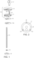
- a first embodiment of toilet seat hinge includes a hinge base 10 comprising a fixing part 11 and a cover 12, a threaded fixing bolt 13, and a pillar 14.
- the fixing part 11 is fixed to the upper surface of a toilet pan 15 by a bonding component adhesivised on both sides thereof, preferably a very high bond (VHB) double sided tape 16, which adheres on one side to a contact surface 17 of the fixing part 11, and on the other side to the toilet pan 15.
- VHB very high bond
- a protective paper covering 16a is provided to cover the VHB tape on that surface that is to bond to the pan, prior to installation of the hinge.
- the cover 12 At installation with the fixing part 11 secured in position, the cover 12 is located over the fixing part and is secured in position by the threaded fixing bolt 13.
- the bolt 13 In the conventional manner, the bolt 13 is engaged at one end in the cover 12, is passed through locating holes (not shown) in the pan 15, and is secured on the underside of the pan using a nut 18 and washer 19. Tightening of the nut 18 clamps the contact surface 17, with attached VHB tape 16, against the toilet pan and thus ensures that a very secure connection is achieved between the hinge and the pan.
- the hinge is what is referred to in the trade as a bottom-fixing hinge.
- the hinge is a top-fixing hinge.
- the invention described herein is applicable to both forms of hinge.
- a characterising feature of the invention is that the hinge can be moved freely and located in the desired position relative to the pan, and then secured in position on the pan, without the need for any trial assembly.
- a spacing facility is provided that is configured to space the contact surface 17, and the VHB tape (with cover paper 16a removed therefrom) from the pan while the hinge base is positioned in the correct location.
- the hinge base When in the correct location, the hinge base is displaced toward the pan, and the spacing facility is displaced or deformed until the VHB tape comes into contact with the pan.
- the displacing force applied to the hinge base may be applied manually and/or may be effected by tightening the nut 18.
- the spacing facility is formed as an integral part of the hinge base and projects from the periphery of the contact surface 17.
- three projections 20 are spaced around the periphery of the contact surface 17 and project outwardly from the plane of the surface.
- the projections are preferably equi-spaced around the periphery to provide the necessary support function, and each has a vee-shaped central formation 21 to assist deformation and/or fracturing. Underlying each of the projections is a recess 22.
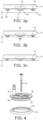
- FIG. 4 parts of a second unclaimed embodiment of hinge are shown, this embodiment including a hinge base 30, a hinge connector 31 projecting upwardly from the base, a fixing bolt 32, and a spacer 33.
- a disc 34 of VHB tape is fixed to the underside of the base 30 and the underside of this disc is maintained out of contact with the surface of the toilet pan, while the base is positioned in the desired location relative to the pan.
- the spacer comprises a ring having an inner annular surface 35 that engages a downward spigot 36 forming part of the base 30.
- the spigot 36 may be a firm frictional fit within the spacer 33 or the surfaces 35 and 36 may be formed with complimentary projection and socket.
- the interengagement of base and spacer is configured to ensure the VHB tape is held clear of the pan during positioning of the base 30 but, once the base is correctly positioned, the application of manual pressure, or pressure applied by tightening the fixing bolt 32, will overcome any resistance between the base 30 and the spacer 33, causing the spigot 36 to slide within the spacer until the VHB tape contacts and bonds to the surface of the pan.
- Figure 5a shows the base 30 in the raised position relative to the pan 15 while Figure 5b shows the base 30 displaced so that the VHB tape is bonded to the pan.
- a hinge base 40 for connection to a surface 15 of a toilet pan using a disc 41 of VHB tape.
- a spacer 42 which comprises a base plate 43 having a number of spikes 44 projecting downwardly therefrom.
- the base 40 and VHB tape 41 are formed with holes 45 in positions that correspond to the positions of spikes 44 and thus the spikes can be engaged through the holes 45 to engage the surface 15 of the pan.
- the length of the spikes 44 is greater than the thickness of the base 40 and thus with the spacer 42 fully engaged with the in the desired location, it may be displaced downwardly whereupon the spikes 44 dis-engage from holes 45 and the VHB disc can engage and bond to the surface 15 as shown in Fig 6b . The spacer 42 can then be removed completely.
- any suitable means can be provided to maintain the base 40 in the upward position shown in Figure 6a , during positioning of the base 40.
- the spikes 44 and holes 45 may be configured to provide friction between the two when in the position shown in Figure 6a .
- Other means such as engaging projections and recesses could be used and a further option would be to use a relatively low bond double-sided adhesive tape between the under side of plate 43 and the upper side of the base 40.
- the invention provides a novel and useful means of mounting the hinge pillar 14, to the hinge base and, in particular, to the cover 12.
- the positions of hinge fixings 11, covers 12 and pillars 14 must be manipulated to ensure that the seat is correctly located along fore and aft, and lateral, axes.
- changing the position of one component affects the positions of the others and so a trial installation is undertaken in which the components are loosely interconnected, the correct positions are established and noted, and the components then disassembled, tightened and fixed back in the established positions.
- the present invention proposes an apparatus which eliminate the need for pre-assembly and allow correct positioning of components, and secure fixing, from the outset.
Landscapes
- Health & Medical Sciences (AREA)
- Public Health (AREA)
- Toilet Supplies (AREA)
Claims (7)
- Ein Scharnier zum Befestigen eines Toilettensitzes auf einer Toilettenschüssel, wobei das Scharnier eine Scharnierbasis (10) mit einer Kontaktoberfläche (17) umfasst, die mit der Schüssel (15) in Eingriff gebracht werden kann, wobei die Kontaktoberfläche damit im Eingriff eine Bindungskomponente (16) aufweist, die zum Fixieren der Kontaktoberfläche (17) an der Schüssel auf beiden Seiten davon mit Haftstoff versehen ist, wobei das Scharnier eine Beabstandungseinrichtung (20) umfasst, die konfiguriert ist, um einen Raum zwischen der Bindungskomponente (16) und der Schüssel zu halten, wobei die Beabstandungseinrichtung (20) durch die Anwendung einer Kraft auf die Scharnierbasis (10) gegen die Schüssel verformbar ist, um der Bindungskomponente das Kontaktieren und das Anhaften des Scharniers an der Schüssel zu ermöglichen, dadurch gekennzeichnet, dass die Beabstandungseinrichtung (20) integral mit der Kontaktoberfläche (17) gebildet ist und konfiguriert ist, um bei Verschiebung der Scharnierbasis in Kontakt mit der Schüssel zu zerbrechen, und wobei das Scharnier ferner eine Fixierstange (13) umfasst, die durch ein Loch in der Schüssel lokalisiert werden kann.
- Scharnier gemäß Anspruch 1, wobei die Scharnierbasis (10) Folgendes beinhaltet: ein Fixierteil (11), das die Kontaktoberfläche (17) umfasst; und eine Abdeckung (12), die über dem Fixierteil in Eingriff gebracht werden kann.
- Scharnier gemäß Anspruch 2, wobei das Fixierteil (11) ferner eine Apertur umfasst, durch die, bei Verwendung, die Fixierstange (13) hindurchgehen kann.
- Scharnier gemäß Anspruch 1, wobei die Bindungskomponente (16) aus einem Band mit sehr hoher Bindung (VHB) gebildet ist.
- Scharnier gemäß Anspruch 1, wobei die Kontaktoberfläche Aperturen (22) aufweist, um die Beabstandungseinrichtung (20) aufzunehmen, während das Scharnier in Kontakt mit der Schüssel (15) verschoben wird.
- Scharnier gemäß einem der vorhergehenden Ansprüche, das ferner Folgendes beinhaltet: einen Pfeiler (14), der an der Scharnierbasis zum schwenkenden Eingriff mit einem Toilettensitz befestigt ist; und ein Fixierungselement (25), um den Pfeiler (14) an der Scharnierbasis zu fixieren; wobei das Scharnier dadurch gekennzeichnet ist, dass eine Zwischenbefestigung (26) bereitgestellt wird, wobei das Fixierungselement (25) den Pfeiler (14) an der Zwischenbefestigung (26) fixiert und die Zwischenbefestigung (26) drehbar in der Scharnierbasis (10) lokalisiert ist.
- Scharnier gemäß Anspruch 6, wobei die Scharnierbasis (10) Folgendes umfasst: ein Fixierteil, das mit einer Toilettenschüssel in Eingriff gebracht werden kann, und eine Abdeckung, die über dem Fixierteil in Eingriff gebracht kann, wobei der Pfeiler (14) durch die Zwischenbefestigung auf der Abdeckung (12) befestigt ist.
Applications Claiming Priority (1)
| Application Number | Priority Date | Filing Date | Title |
|---|---|---|---|
| PCT/GB2017/050473 WO2018154261A1 (en) | 2017-02-23 | 2017-02-23 | Mounting method and/or apparatus for mounting a toilet seat |
Publications (3)
| Publication Number | Publication Date |
|---|---|
| EP3585227A1 EP3585227A1 (de) | 2020-01-01 |
| EP3585227B1 true EP3585227B1 (de) | 2024-11-13 |
| EP3585227C0 EP3585227C0 (de) | 2024-11-13 |
Family
ID=58228346
Family Applications (1)
| Application Number | Title | Priority Date | Filing Date |
|---|---|---|---|
| EP17708873.9A Active EP3585227B1 (de) | 2017-02-23 | 2017-02-23 | Montageverfahren und/oder vorrichtung zur montage eines toilettensitzes |
Country Status (4)
| Country | Link |
|---|---|
| US (2) | US20200008633A1 (de) |
| EP (1) | EP3585227B1 (de) |
| ES (1) | ES2994292T3 (de) |
| WO (1) | WO2018154261A1 (de) |
Families Citing this family (3)
| Publication number | Priority date | Publication date | Assignee | Title |
|---|---|---|---|---|
| GB2573540B (en) * | 2018-05-09 | 2021-04-07 | Norcros Group Holdings Ltd | Mounting method and apparatus |
| DE102020107947A1 (de) | 2020-03-23 | 2021-09-23 | Hamberger Industriewerke Gmbh | Befestigungsvorrichtung |
| US11987967B1 (en) * | 2023-06-05 | 2024-05-21 | Patrick Gerard Stack | High efficiency toilet |
Family Cites Families (8)
| Publication number | Priority date | Publication date | Assignee | Title |
|---|---|---|---|---|
| DK176340B1 (da) * | 2004-07-12 | 2007-08-27 | Pressalit Group As | Indstilleligt toilethængselbeslag |
| US8310369B1 (en) * | 2009-03-27 | 2012-11-13 | Nth Solutions, Llc | Detecting unintended flush toilet water flow |
| GB2511790B (en) * | 2013-03-13 | 2018-03-14 | Croydex Ltd | Toilet seat mounting method and apparatus |
| DE202013102982U1 (de) * | 2013-04-09 | 2014-07-14 | Glabete Gmbh | Magnetischer Systembaukasten und Ausstattungsserie |
| CN203576408U (zh) * | 2013-10-31 | 2014-05-07 | 彭东 | 用于连接马桶盖板与马桶座体的支座组件 |
| CN104095581B (zh) * | 2014-07-18 | 2016-01-27 | 厦门豪帝卫浴工业有限公司 | 一种子座圈易拆装的座便器盖板 |
| CN204105870U (zh) * | 2014-09-01 | 2015-01-21 | 彭东 | 具有定位功能的马桶支座 |
| CN204971084U (zh) * | 2015-08-17 | 2016-01-20 | 乐特瑞(厦门)卫浴有限公司 | 一种一键式马桶盖板快速拆装装置 |
-
2017
- 2017-02-23 WO PCT/GB2017/050473 patent/WO2018154261A1/en not_active Ceased
- 2017-02-23 US US16/488,066 patent/US20200008633A1/en not_active Abandoned
- 2017-02-23 EP EP17708873.9A patent/EP3585227B1/de active Active
- 2017-02-23 ES ES17708873T patent/ES2994292T3/es active Active
-
2021
- 2021-03-12 US US17/199,634 patent/US11589718B2/en active Active
Also Published As
| Publication number | Publication date |
|---|---|
| US20210196089A1 (en) | 2021-07-01 |
| US20200008633A1 (en) | 2020-01-09 |
| EP3585227A1 (de) | 2020-01-01 |
| US11589718B2 (en) | 2023-02-28 |
| ES2994292T3 (en) | 2025-01-21 |
| WO2018154261A1 (en) | 2018-08-30 |
| EP3585227C0 (de) | 2024-11-13 |
Similar Documents
| Publication | Publication Date | Title |
|---|---|---|
| US11589718B2 (en) | Mounting method and/or apparatus for mounting a toilet seat | |
| US7581913B2 (en) | Seal nut assembly and method of manufacture | |
| CN102102696B (zh) | 带有耳状外扩部的螺母 | |
| JP6816050B2 (ja) | 電子機器固定用ブラケット及び電子機器固定構造 | |
| GB2546799A (en) | Mounting method and apparatus | |
| DE10113044C2 (de) | System zur Befestigung eines Bauteils an einem Trägerbauteil | |
| DE102012218168B3 (de) | Glastürscharnier | |
| US20160029861A1 (en) | Mounting method and apparatus | |
| JP2018526187A (ja) | 飲料プレス器及び方法 | |
| JP4720841B2 (ja) | 舌付き座金固定治具 | |
| GB2573540A (en) | Mounting method and apparatus | |
| GB2592823A (en) | Toilet seat mounting apparatus | |
| EP1918445A1 (de) | Laugenbehälter mit Ballastgewicht für eine Waschmaschine | |
| EP0939710B1 (de) | Verfahren zur montage einer wischeranlage und wischeranlage. | |
| EP1918444B1 (de) | Laugenbehälter mit Ballastgewicht für eine Waschmaschine | |
| JP2008267564A (ja) | 機器取付装置 | |
| KR20240073743A (ko) | 홈이 형성된 기둥재용 부착 부재 및 그 체결구 | |
| JP6446720B2 (ja) | 棚用取付け部材 | |
| JP6742017B2 (ja) | スパッタ付着防止具 | |
| DE60009401T2 (de) | Vorrichtung zum Befestigen eines Hitzeschildes für eine Ölpumpe | |
| EP4491889A1 (de) | Blindbefestigungsvorrichtung zur befestigung eines teils an einem basisteil | |
| JPH0640334Y2 (ja) | ボルト・ナットの回り止め装置 | |
| WO2020139274A2 (en) | An apparatus and a method for fixing | |
| EP4074988A1 (de) | Unverlierbarer verbinder und verfahren zum verbinden | |
| JP3118812U (ja) | 座金 |
Legal Events
| Date | Code | Title | Description |
|---|---|---|---|
| STAA | Information on the status of an ep patent application or granted ep patent |
Free format text: STATUS: UNKNOWN |
|
| STAA | Information on the status of an ep patent application or granted ep patent |
Free format text: STATUS: THE INTERNATIONAL PUBLICATION HAS BEEN MADE |
|
| PUAI | Public reference made under article 153(3) epc to a published international application that has entered the european phase |
Free format text: ORIGINAL CODE: 0009012 |
|
| STAA | Information on the status of an ep patent application or granted ep patent |
Free format text: STATUS: REQUEST FOR EXAMINATION WAS MADE |
|
| 17P | Request for examination filed |
Effective date: 20190912 |
|
| AK | Designated contracting states |
Kind code of ref document: A1 Designated state(s): AL AT BE BG CH CY CZ DE DK EE ES FI FR GB GR HR HU IE IS IT LI LT LU LV MC MK MT NL NO PL PT RO RS SE SI SK SM TR |
|
| AX | Request for extension of the european patent |
Extension state: BA ME |
|
| DAV | Request for validation of the european patent (deleted) | ||
| DAX | Request for extension of the european patent (deleted) | ||
| STAA | Information on the status of an ep patent application or granted ep patent |
Free format text: STATUS: EXAMINATION IS IN PROGRESS |
|
| 17Q | First examination report despatched |
Effective date: 20220221 |
|
| GRAP | Despatch of communication of intention to grant a patent |
Free format text: ORIGINAL CODE: EPIDOSNIGR1 |
|
| STAA | Information on the status of an ep patent application or granted ep patent |
Free format text: STATUS: GRANT OF PATENT IS INTENDED |
|
| INTG | Intention to grant announced |
Effective date: 20240620 |
|
| GRAS | Grant fee paid |
Free format text: ORIGINAL CODE: EPIDOSNIGR3 |
|
| GRAA | (expected) grant |
Free format text: ORIGINAL CODE: 0009210 |
|
| STAA | Information on the status of an ep patent application or granted ep patent |
Free format text: STATUS: THE PATENT HAS BEEN GRANTED |
|
| AK | Designated contracting states |
Kind code of ref document: B1 Designated state(s): AL AT BE BG CH CY CZ DE DK EE ES FI FR GB GR HR HU IE IS IT LI LT LU LV MC MK MT NL NO PL PT RO RS SE SI SK SM TR |
|
| REG | Reference to a national code |
Ref country code: GB Ref legal event code: FG4D |
|
| REG | Reference to a national code |
Ref country code: CH Ref legal event code: EP |
|
| REG | Reference to a national code |
Ref country code: DE Ref legal event code: R096 Ref document number: 602017086081 Country of ref document: DE |
|
| REG | Reference to a national code |
Ref country code: IE Ref legal event code: FG4D |
|
| U01 | Request for unitary effect filed |
Effective date: 20241125 |
|
| U07 | Unitary effect registered |
Designated state(s): AT BE BG DE DK EE FI FR IT LT LU LV MT NL PT RO SE SI Effective date: 20241202 |
|
| REG | Reference to a national code |
Ref country code: ES Ref legal event code: FG2A Ref document number: 2994292 Country of ref document: ES Kind code of ref document: T3 Effective date: 20250121 |
|
| U20 | Renewal fee for the european patent with unitary effect paid |
Year of fee payment: 9 Effective date: 20250122 |
|
| PG25 | Lapsed in a contracting state [announced via postgrant information from national office to epo] |
Ref country code: HR Free format text: LAPSE BECAUSE OF FAILURE TO SUBMIT A TRANSLATION OF THE DESCRIPTION OR TO PAY THE FEE WITHIN THE PRESCRIBED TIME-LIMIT Effective date: 20241113 Ref country code: IS Free format text: LAPSE BECAUSE OF FAILURE TO SUBMIT A TRANSLATION OF THE DESCRIPTION OR TO PAY THE FEE WITHIN THE PRESCRIBED TIME-LIMIT Effective date: 20250313 |
|
| PGFP | Annual fee paid to national office [announced via postgrant information from national office to epo] |
Ref country code: ES Payment date: 20250310 Year of fee payment: 9 |
|
| PGFP | Annual fee paid to national office [announced via postgrant information from national office to epo] |
Ref country code: IE Payment date: 20250123 Year of fee payment: 9 |
|
| PG25 | Lapsed in a contracting state [announced via postgrant information from national office to epo] |
Ref country code: NO Free format text: LAPSE BECAUSE OF FAILURE TO SUBMIT A TRANSLATION OF THE DESCRIPTION OR TO PAY THE FEE WITHIN THE PRESCRIBED TIME-LIMIT Effective date: 20250213 |
|
| PG25 | Lapsed in a contracting state [announced via postgrant information from national office to epo] |
Ref country code: GR Free format text: LAPSE BECAUSE OF FAILURE TO SUBMIT A TRANSLATION OF THE DESCRIPTION OR TO PAY THE FEE WITHIN THE PRESCRIBED TIME-LIMIT Effective date: 20250214 |
|
| PG25 | Lapsed in a contracting state [announced via postgrant information from national office to epo] |
Ref country code: PL Free format text: LAPSE BECAUSE OF FAILURE TO SUBMIT A TRANSLATION OF THE DESCRIPTION OR TO PAY THE FEE WITHIN THE PRESCRIBED TIME-LIMIT Effective date: 20241113 |
|
| PG25 | Lapsed in a contracting state [announced via postgrant information from national office to epo] |
Ref country code: RS Free format text: LAPSE BECAUSE OF FAILURE TO SUBMIT A TRANSLATION OF THE DESCRIPTION OR TO PAY THE FEE WITHIN THE PRESCRIBED TIME-LIMIT Effective date: 20250213 |
|
| PG25 | Lapsed in a contracting state [announced via postgrant information from national office to epo] |
Ref country code: SM Free format text: LAPSE BECAUSE OF FAILURE TO SUBMIT A TRANSLATION OF THE DESCRIPTION OR TO PAY THE FEE WITHIN THE PRESCRIBED TIME-LIMIT Effective date: 20241113 |
|
| PG25 | Lapsed in a contracting state [announced via postgrant information from national office to epo] |
Ref country code: SK Free format text: LAPSE BECAUSE OF FAILURE TO SUBMIT A TRANSLATION OF THE DESCRIPTION OR TO PAY THE FEE WITHIN THE PRESCRIBED TIME-LIMIT Effective date: 20241113 |
|
| PG25 | Lapsed in a contracting state [announced via postgrant information from national office to epo] |
Ref country code: CZ Free format text: LAPSE BECAUSE OF FAILURE TO SUBMIT A TRANSLATION OF THE DESCRIPTION OR TO PAY THE FEE WITHIN THE PRESCRIBED TIME-LIMIT Effective date: 20241113 |
|
| PG25 | Lapsed in a contracting state [announced via postgrant information from national office to epo] |
Ref country code: MC Free format text: LAPSE BECAUSE OF FAILURE TO SUBMIT A TRANSLATION OF THE DESCRIPTION OR TO PAY THE FEE WITHIN THE PRESCRIBED TIME-LIMIT Effective date: 20241113 |
|
| PLBE | No opposition filed within time limit |
Free format text: ORIGINAL CODE: 0009261 |
|
| STAA | Information on the status of an ep patent application or granted ep patent |
Free format text: STATUS: NO OPPOSITION FILED WITHIN TIME LIMIT |
|
| REG | Reference to a national code |
Ref country code: CH Ref legal event code: PL |
|
| PG25 | Lapsed in a contracting state [announced via postgrant information from national office to epo] |
Ref country code: CH Free format text: LAPSE BECAUSE OF NON-PAYMENT OF DUE FEES Effective date: 20250228 |
|
| 26N | No opposition filed |
Effective date: 20250814 |
|
| GBPC | Gb: european patent ceased through non-payment of renewal fee |
Effective date: 20250223 |
|
| PG25 | Lapsed in a contracting state [announced via postgrant information from national office to epo] |
Ref country code: GB Free format text: LAPSE BECAUSE OF NON-PAYMENT OF DUE FEES Effective date: 20250223 |