EP3584645B1 - Timepiece comprising a mechanical movement of which the operation is controlled by an electromechanical device - Google Patents
Timepiece comprising a mechanical movement of which the operation is controlled by an electromechanical device Download PDFInfo
- Publication number
- EP3584645B1 EP3584645B1 EP19175180.9A EP19175180A EP3584645B1 EP 3584645 B1 EP3584645 B1 EP 3584645B1 EP 19175180 A EP19175180 A EP 19175180A EP 3584645 B1 EP3584645 B1 EP 3584645B1
- Authority
- EP
- European Patent Office
- Prior art keywords
- mechanical resonator
- alternation
- stopping member
- oscillation
- mechanical
- Prior art date
- Legal status (The legal status is an assumption and is not a legal conclusion. Google has not performed a legal analysis and makes no representation as to the accuracy of the status listed.)
- Active
Links
- 230000033001 locomotion Effects 0.000 title claims description 53
- 230000010355 oscillation Effects 0.000 claims description 75
- 230000003993 interaction Effects 0.000 claims description 42
- 230000007935 neutral effect Effects 0.000 claims description 36
- 238000001514 detection method Methods 0.000 claims description 19
- 230000007246 mechanism Effects 0.000 claims description 10
- 230000001105 regulatory effect Effects 0.000 claims description 9
- 230000035939 shock Effects 0.000 claims description 6
- 230000002123 temporal effect Effects 0.000 claims description 5
- 238000012423 maintenance Methods 0.000 claims description 4
- 230000003287 optical effect Effects 0.000 claims description 4
- 230000001939 inductive effect Effects 0.000 claims description 2
- 238000005381 potential energy Methods 0.000 claims description 2
- 230000010363 phase shift Effects 0.000 description 14
- 230000009471 action Effects 0.000 description 4
- 239000010453 quartz Substances 0.000 description 4
- VYPSYNLAJGMNEJ-UHFFFAOYSA-N silicon dioxide Inorganic materials O=[Si]=O VYPSYNLAJGMNEJ-UHFFFAOYSA-N 0.000 description 4
- 230000002745 absorbent Effects 0.000 description 3
- 239000002250 absorbent Substances 0.000 description 3
- 230000000903 blocking effect Effects 0.000 description 3
- 230000002457 bidirectional effect Effects 0.000 description 2
- 230000000737 periodic effect Effects 0.000 description 2
- 238000011084 recovery Methods 0.000 description 2
- 101100171060 Caenorhabditis elegans div-1 gene Proteins 0.000 description 1
- 238000003457 Shi epoxidation reaction Methods 0.000 description 1
- 230000004913 activation Effects 0.000 description 1
- 230000008901 benefit Effects 0.000 description 1
- 238000010586 diagram Methods 0.000 description 1
- 238000006073 displacement reaction Methods 0.000 description 1
- 230000000694 effects Effects 0.000 description 1
- 239000003302 ferromagnetic material Substances 0.000 description 1
- 239000000463 material Substances 0.000 description 1
- 238000005259 measurement Methods 0.000 description 1
- 230000003071 parasitic effect Effects 0.000 description 1
- 230000000284 resting effect Effects 0.000 description 1
Images


Classifications
-
- G—PHYSICS
- G04—HOROLOGY
- G04B—MECHANICALLY-DRIVEN CLOCKS OR WATCHES; MECHANICAL PARTS OF CLOCKS OR WATCHES IN GENERAL; TIME PIECES USING THE POSITION OF THE SUN, MOON OR STARS
- G04B17/00—Mechanisms for stabilising frequency
- G04B17/20—Compensation of mechanisms for stabilising frequency
-
- G—PHYSICS
- G04—HOROLOGY
- G04B—MECHANICALLY-DRIVEN CLOCKS OR WATCHES; MECHANICAL PARTS OF CLOCKS OR WATCHES IN GENERAL; TIME PIECES USING THE POSITION OF THE SUN, MOON OR STARS
- G04B18/00—Mechanisms for setting frequency
- G04B18/04—Adjusting the beat of the pendulum, balance, or the like, e.g. putting into beat
-
- G—PHYSICS
- G04—HOROLOGY
- G04C—ELECTROMECHANICAL CLOCKS OR WATCHES
- G04C3/00—Electromechanical clocks or watches independent of other time-pieces and in which the movement is maintained by electric means
- G04C3/04—Electromechanical clocks or watches independent of other time-pieces and in which the movement is maintained by electric means wherein movement is regulated by a balance
- G04C3/042—Electromechanical clocks or watches independent of other time-pieces and in which the movement is maintained by electric means wherein movement is regulated by a balance using mechanical coupling
- G04C3/045—Electromechanical clocks or watches independent of other time-pieces and in which the movement is maintained by electric means wherein movement is regulated by a balance using mechanical coupling with constant impulses
-
- G—PHYSICS
- G04—HOROLOGY
- G04C—ELECTROMECHANICAL CLOCKS OR WATCHES
- G04C11/00—Synchronisation of independently-driven clocks
- G04C11/08—Synchronisation of independently-driven clocks using an electro-magnet or-motor for oscillation correction
- G04C11/081—Synchronisation of independently-driven clocks using an electro-magnet or-motor for oscillation correction using an electro-magnet
- G04C11/084—Synchronisation of independently-driven clocks using an electro-magnet or-motor for oscillation correction using an electro-magnet acting on the balance
-
- G—PHYSICS
- G04—HOROLOGY
- G04C—ELECTROMECHANICAL CLOCKS OR WATCHES
- G04C11/00—Synchronisation of independently-driven clocks
-
- G—PHYSICS
- G04—HOROLOGY
- G04C—ELECTROMECHANICAL CLOCKS OR WATCHES
- G04C11/00—Synchronisation of independently-driven clocks
- G04C11/08—Synchronisation of independently-driven clocks using an electro-magnet or-motor for oscillation correction
- G04C11/085—Synchronisation of independently-driven clocks using an electro-magnet or-motor for oscillation correction using an electro-motor
- G04C11/088—Synchronisation of independently-driven clocks using an electro-magnet or-motor for oscillation correction using an electro-motor acting on the balance
-
- G—PHYSICS
- G04—HOROLOGY
- G04C—ELECTROMECHANICAL CLOCKS OR WATCHES
- G04C13/00—Driving mechanisms for clocks by master-clocks
- G04C13/02—Circuit arrangements; Electric clock installations
-
- G—PHYSICS
- G04—HOROLOGY
- G04C—ELECTROMECHANICAL CLOCKS OR WATCHES
- G04C13/00—Driving mechanisms for clocks by master-clocks
- G04C13/02—Circuit arrangements; Electric clock installations
- G04C13/028—Circuit arrangements; Electric clock installations transmission systems for synchronisation of pendulum of slave-clocks by pendulums of master-clocks
-
- G—PHYSICS
- G04—HOROLOGY
- G04C—ELECTROMECHANICAL CLOCKS OR WATCHES
- G04C3/00—Electromechanical clocks or watches independent of other time-pieces and in which the movement is maintained by electric means
- G04C3/04—Electromechanical clocks or watches independent of other time-pieces and in which the movement is maintained by electric means wherein movement is regulated by a balance
- G04C3/042—Electromechanical clocks or watches independent of other time-pieces and in which the movement is maintained by electric means wherein movement is regulated by a balance using mechanical coupling
-
- G—PHYSICS
- G04—HOROLOGY
- G04D—APPARATUS OR TOOLS SPECIALLY DESIGNED FOR MAKING OR MAINTAINING CLOCKS OR WATCHES
- G04D7/00—Measuring, counting, calibrating, testing or regulating apparatus
- G04D7/12—Timing devices for clocks or watches for comparing the rate of the oscillating member with a standard
- G04D7/1257—Timing devices for clocks or watches for comparing the rate of the oscillating member with a standard wherein further adjustment devices are present
- G04D7/1264—Timing devices for clocks or watches for comparing the rate of the oscillating member with a standard wherein further adjustment devices are present for complete clockworks
Definitions
- timing the operation of a mechanism is understood the fact of timing the movement of the movable elements of this mechanism when it is operating, in particular to determine the rotational speeds of its wheels.
- the mechanical resonator is a sprung balance and the maintenance device comprises a conventional escapement, for example with a Swiss lever.
- the auxiliary oscillator is formed in particular by a quartz resonator or by a resonator integrated in an electronic circuit.
- the aim is to synchronize the frequency of the mechanical oscillator with that of a quartz oscillator by an interaction between the finger and the stop when the mechanical oscillator exhibits a time drift relative to a frequency of instruction, the finger being provided to be able to either momentarily block the balance which is then stopped in its movement for a certain time interval (the stop resting against the finger moved in its direction during a return of the balance in the direction of its neutral position), or limit the amplitude of oscillation when the finger arrives against the stop while the balance turns in the direction of one of its two extreme angular positions (defining its amplitude), the finger then stopping the oscillation and the balance starting directly in the opposite direction.
- the movement of the finger is provided to make it possible to stop the balance by contact with the stop, but the finger is arranged so as not to come into contact with the rim of the balance.
- the instant of an interaction between the finger and the stopper also depends on the amplitude of the oscillation of the sprung balance.
- the desired synchronization appears improbable. This is because, in particular for a sprung balance whose frequency is greater than the setpoint frequency timing the back and forth movements of the finger and with a first interaction between the finger and the stopper which momentarily retains the balance returning from one of its two extreme angular positions (correction reducing the error), the second interaction, after numerous oscillations without the stop touching the finger during its reciprocating movement, will certainly be a stop of the balance by the finger with immediate reversal of its direction of motion. oscillation, by the fact that the stop abuts against the finger while the balance rotates in the direction of said extreme angular position (correction increasing the error).
- the document EP 1164441 A1 describes a mechanical timepiece associated with an electromechanical device for correcting a temporal drift of its sprung balance forming, with a conventional escapement, a mechanical oscillator.
- This first embodiment has various drawbacks, in particular because it is only capable of correcting an advance in the rate of the timepiece; which requires adjusting the mechanical oscillator so that its frequency is greater than a nominal frequency. Then, stopping the sprung balance close to its neutral position generates a relatively large shock between the balance and the fork of the anchor. In addition, when the escape wheel is released again, the sprung balance is initially stationary because it will have almost no initial amplitude. Although the sprung balance is stopped indirectly since the electromechanical correction device provided blocks the escape wheel, the preamble of claim 1 appended refers to this first embodiment.
- the second embodiment described in the document EP 1164441 A1 has the advantage of allowing a correction of an advance or a delay in the operation of the timepiece.
- this second embodiment relates to a relatively complex electromechanical correction device which is arranged so as to be able to vary the active length of the hairspring forming the sprung balance.
- An aim of the present invention is to find a solution to the technical problems and drawbacks of the prior art mentioned in the technological background.
- a mechanical watch movement In the context of the present invention, it is generally sought to improve the precision of the rate of a mechanical watch movement, that is to say to reduce the daily time drift of this mechanical movement.
- the present invention seeks to achieve such an aim for a mechanical watch movement, the rate of which is initially adjusted as well as possible.
- a general aim of the invention is to find a device for correcting a temporal drift of a movement. mechanical, namely a device for correcting its rate to increase its precision, without however renouncing that it can operate independently with the best precision that it is possible for it to have thanks to its own characteristics, c 'that is to say in the absence of the correction device or when the latter is inactive.
- the present invention relates to a timepiece as defined in claim 1 attached.
- the characteristics of the invention it is possible to reliably and efficiently regulate the rate of the mechanical movement, whether the latter has a time drift corresponding to a certain delay or to a certain advance.
- the electromechanical device is formed by an actuator comprising a stop member defining a movable stop for a projecting part of the mechanical resonator, the stop member being arranged movable between a non-interaction position, where it is outside a space swept by the protruding part when the mechanical resonator oscillates with an amplitude in the useful operating range, and an interaction position where it is partially located in this space swept by the protruding part.
- the stop member can be actuated on command to stop, via the protruding part abutting against the stop member then placed in its interaction position, the oscillating movement of the mechanical resonator in the direction of alternation given and selectively in the first half-wave or the second half-wave of this half-wave according to whether, respectively, at least a certain advance or at least a certain delay has been detected.
- the electromechanical device is arranged so that, when the stop member is actuated to stop the mechanical resonator in a first half-wave, the stop member momentarily prevents, after the projecting part has abutted against this stop member, the mechanical resonator from continue the movement of natural oscillation specific to this first half-cycle, so that this movement of natural oscillation during the first half-cycle is momentarily interrupted before it is continued, with a certain time phase shift, after removal of the shut-off device.
- the electromechanical device is arranged so that, when the stop member is actuated to stop the mechanical resonator in a second half-wave, it thus prematurely ends this second half-wave without blocking the resonator.
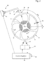
- a timepiece 2 comprises a watch movement 4 and a regulating device 22 designed to be able to generate phase shifts in the oscillation movement of a mechanical resonator 6 arranged to clock the rate of the watch movement 4.
- the mechanical movement 4 comprises at least one mechanism 12 indicating a temporal datum, this mechanism comprising a gear 16 driven by a barrel 14.
- the mechanical resonator 6 is formed by a balance 8 and a hairspring 10.
- the indicator mechanism 12 comprises a maintenance device of the mechanical resonator, this maintenance device being formed by an escapement 18.
- the escapement and the mechanical resonator constitute a mechanical oscillator.
- the escapement conventionally comprises an anchor and an escape wheel, the latter being kinematically connected to the barrel via the gear 16.
- the mechanical resonator is capable of oscillating around a neutral position (rest position / angular position zero), corresponding to its state of minimum potential energy, along a circular geometric axis, that is to say to present an angular oscillation movement around the axis of rotation 9 of the balance.
- a neutral position rest position / angular position zero
- the radius of the circular geometric axis is unimportant.
- the axis of oscillation defines a direction of oscillation which indicates the nature of the movement of the mechanical resonator, which may be linear in another specific embodiment.
- Each oscillation of the mechanical resonator has two successive alternations between two extreme positions on the axis of oscillation, these extreme positions defining the amplitude of oscillation of the mechanical oscillator from the neutral position.
- the actuator 28 comprises an electrical actuation circuit 29 and a stop member 30 of the mechanical resonator which is formed by a movable stop, which is defined in the variant of Figure 2 by a finger arranged at the end of a bar 31 made of piezoelectric material. This bar flexes when an electric voltage is applied by the electric circuit 29 between two electrodes arranged on two opposite faces of its side faces.
- the circuit 29 is connected to the regulation circuit 24 which supplies it with a control signal Sc to actuate the movable stop 30 in the direction of the rim of the balance without however touching it.
- the actuator comprises an electromagnetic system arranged to be able to move the stop member on command between a position of interaction with the projection 20 and a position of non-interaction.
- This system electromagnetic can be formed by a fixed coil and a magnet placed on a flexible bar carrying a finger defining the stop, or vice versa.
- the movable stopper can be formed by a core made of ferromagnetic material which penetrates inside a coil, which moves this core along its central axis when it is supplied (a return spring is for example associated with the core) .
- the senor 32 is an optical sensor comprising a light source, arranged so as to be able to send a beam of light in the direction of the rim of the balance whose lateral surface 48 is reflective (in particular polished), and a detector light arranged to receive in return a light signal 33 reflected by the side surface.
- the optical sensor is provided here to detect the passage of the mechanical resonator through its neutral position and also to detect the direction of the oscillation movement so as to determine in which alternation of the oscillation, among the two alternations defining each oscillation period , this detection takes place. For this purpose, provision is made to vary the intensity of the detected optical signal S L as a function of the angular position of the mechanical resonator.
- the side surface 48 comprises a marking 50 (shown in Figure 2 on the rim for the purpose of explaining the detection) consisting of two absorbent zones of different widths.
- the zero crossing is defined by the interior line (relative to the pattern formed by the two absorbent zones) of the zone of greatest width. It will be understood that the different widths of the two absorbent zones easily make it possible to determine the direction of rotation of the balance 8.
- the signal S N can indicate for each detection of the marking the direction of oscillation to the logic circuit 42 or indicate to it only when a predefined alternation per period of oscillation is in progress, given that the interaction between the actuator and the balance is provided here only between the passage of the balance through the neutral position in a predefined alternation, selected from the first alternation and the second alternation of a period of oscillation, and the passage of this balance through the neutral position of the 'alternation which succeeds it, as will be clearly understood in the remainder of the description of the invention. It will therefore be noted that, in a variant, the flip-flop 38 can be omitted because the detection circuit can easily transmit a single pulse per period of oscillation via the signal S P.
- either a capacitive sensor or an inductive sensor is provided, arranged so as to be able to detect a variation in capacitance, respectively inductance, as a function of the angular position of the mechanical resonator.
- an energy source associated with a device for storing the electrical energy generated by the energy source.
- the energy source is for example formed by a photovoltaic cell or by a thermoelectric element, these examples being in no way limiting. In the case of a battery, the energy source and the storage device together form one and the same electrical component.
- the regulation device comprises a measuring device 34 arranged to be able to measure, on the basis of a detection signal S L supplied by the sensor 32, a time drift of the mechanical oscillator relative to the auxiliary oscillator 26.
- the measuring device is formed of the detection circuit 36 already described, of a flip-flop 38 and of a bidirectional counter C2 which receives at one of its two inputs the signal S P , which supplies one pulse per period of oscillation. detected using the sensor, and at the other of its inputs a clock signal S hor generated by the auxiliary oscillator 26, the clock circuit 40 of which supplies a reference signal to a divider having two stages DIV1 and DIV2.
- the first stage of the divider supplies a frequency signal to a time counter C1 and to a timer 44.
- the state of the counter C2 thus gives the time drift of the mechanism 12 in absolute value since the activation of the regulation device.
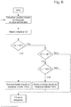
- the state of the counter C2 is supplied to the logic control circuit 42 which is arranged to be able to determine whether the time drift corresponds to at least a certain advance or at least a certain delay, by a comparison with reference values N1 and N2. , as shown in Figure 6 .
- the regulation circuit 24 and the actuator 28 are designed to be able to stop during at least one given half-wave, when the mechanical resonator oscillates with an amplitude included in a useful operating range, the oscillation movement of the mechanical resonator in the direction of this given half-wave and selectively either during a first half-cycle of a given half-wave, occurring before the passage of the mechanical resonator through its neutral position in this given half-wave, when the measured time drift corresponds to at least a certain advance; or during a second half-cycle of at least one given half-cycle, occurring after the mechanical resonator has passed through its neutral position in each given half-cycle, when the measured time drift corresponds to at least a certain delay.
- the oscillation movement is stopped so as to prematurely end each second half-cycle, relative to the nominal duration of a natural half-cycle, and to start the next half-cycle at an intervening time. before this nominal duration has been reached since the last passage of the mechanical resonator through its neutral position.
- the stop member 30 of the actuator 28 defines a movable stop for a projecting part 20 of the mechanical resonator. It will be noted that, preferably, the pendulum is designed so as to be balanced.
- the stop member is arranged to be movable between a non-interaction position, where it is outside a space swept by the projecting part when the mechanical resonator oscillates with an amplitude in the useful operating range, and an interaction position where it is located partially in this space swept by the projecting part so as to be able to stop the balance 8 in the direction of its oscillation movement when the projecting part 20 abuts against the stop member.
- the stop member 30 (which is movable along a substantially radial displacement axis) is positioned angularly, relative to the axis of oscillation of the balance, so that it presents, when it is in its position of 'interaction, a non-zero angular offset ⁇ B with the projecting part 20 of the balance when the mechanical resonator is in its neutral position, which corresponds to the Figure 2 to a positioning of the protrusion 20 at an angular position '0'.
- This angular position is detected by the sensor 32 via the marking 50, which appears opposite this sensor when the protruding part is positioned at the zero angle.
- the angular offset ⁇ B is expected to be less than the minimum amplitude of the useful operating range of the mechanical oscillator so as to allow correction of a time drift in all of this useful operating range.
- the value of the angular offset is between 60 ° and 150 °, preferably between 90 ° and 120 °.
- the angular position ⁇ of the balance 8 as a function of time is shown.
- the logic circuit 42 reinitializes the time counter C1 and detects whether the bidirectional counter C2 has at least a certain advance, that is to say C2> N1, or at least a certain delay, namely C2 ⁇ - N2; N1 and N2 being natural numbers greater than zero.
- Each period of natural oscillation T0 of the mechanical oscillator comprises a first natural half-wave A1, of nominal duration T0 / 2 (oscillation movement in a first direction between two extreme angular positions of the mechanical resonator), and a second natural half-wave A2 (oscillation movement in the opposite direction to the first direction between the two extreme angular positions) of the same nominal duration T0 / 2.
- the first natural half-wave A1 consists of a first half-wave D1 1 , of nominal duration T0 / 4 and occurring before the passage of the mechanical resonator through its neutral position (angular position '0'), and of a second half-wave.
- the second natural half-wave A2 consists of a first half-wave D1 2 , of nominal duration T0 / 4 and occurring before the passage of the mechanical resonator through its neutral position, and of a second half-wave D2 2 of same nominal duration T0 / 4 and occurring after the mechanical resonator has passed through its neutral position.
- the regulation device performs a correction following the detection of a certain delay.
- the stop device is actuated directly after detection of the passage of the balance through the neutral position (signal Sc), for a period of T0 / 4 corresponding to that of a half-wave, to stop the mechanical resonator during the second half-wave D2 2 * of the second half-wave A2 *, that is to say after passing through the neutral position and before reaching the extreme angular position of the natural oscillation (undisturbed oscillation).
- this logic circuit 42 After the logic control circuit 42 has received from the detection circuit 36, via the signal S N , the information that a second half-wave of a half-wave in the counterclockwise direction begins, this logic circuit 42 generates a signal S D for triggering a timer 44 which is arranged so as to supply, following reception of the trigger signal, a control signal Sc to the electric circuit 29 of the actuator 28 to activate the latter for an interval of time T R equal to T0 / 4 in the variant described here.
- the stop member 30 is actuated and placed in its interaction position during the time interval T R.
- the regulating device performs a correction following the detection of a certain advance.
- the stop device is actuated after a time delay of T0 / 4 following detection of the passage of the balance through the neutral position, for a period T0 / 4 corresponding to that of a half-wave, to thus stop the mechanical resonator during the first half-wave D1 1 * of the first half-wave A1 *, that is to say between the extreme angular position of the natural oscillation ending the previous natural half-wave A2 and the passage through the neutral position of the mechanical resonator during the first half-wave A1 *.
- this logic circuit 42 resets time counter C1 and waits for the latter to measure a time interval equal to T0 / 4. Then, it generates a signal S D to trigger the timer 44 which then supplies a control signal Sc to the electric circuit 29 of the actuator 28 to activate the latter during a time interval T R equal to T0 / 4 in the variant described. here.
- this time interval can be provided much longer in order to effect a greater correction.
- the duration of this time interval can be varied as a function of different values detected for the advance of the mechanical oscillator.
- the stop member 30 is actuated substantially at the start of the alternation A1 * and placed in its interaction position during l time interval T R.
- the result of this action is that the projecting part 20 of the balance comes into abutment against the stop member during the first half-cycle in question when the projecting part of the balance reaches the angular position ⁇ B while moving towards the position neutral. This event stops the balance and the stop member momentarily blocks the mechanical resonator so that the first half-wave D1 1 * is momentarily interrupted before it is continued.
- a negative phase shift DN is thus obtained, as shown by the graph of the Figure 4B , and the duration of the alternation A1 * is equal to T4, this value being greater than the nominal value T0 / 2.
- This negative phase shift makes it possible to compensate for a certain advance. This corrective action can be carried out successively in several oscillation periods according to the detected advance.
- the stop member when the stop member ends a second half-wave to correct a delay, it substantially absorbs the kinetic energy of the sprung balance, so that the next first half-wave D1 1 F is started with a speed substantially zero and has substantially a nominal duration T0 / 4.
- the alternation A1 F has substantially a nominal duration T0 / 2 and a lesser amplitude, which depends on the angular offset ⁇ B.
- the interrupted alternation is continued following the withdrawal of the stop member by a recovery alternation having a lesser amplitude and substantially a nominal duration T0 / 2.
- the amplitude of this alternation of recovery is substantially equal to that of the alternation A1 F.
- stopping may have a very short duration even if no specific member comes to block the balance.
- stopping zero speed
- the projecting part of the balance can be arranged differently in other variant embodiments.
- the protruding part is arranged axially below the rim, the stop member being movable in a geometric plane situated below that of the balance and crossed by the protruding part.
- Other variants can be provided by those skilled in the art while remaining within the scope of the present invention.
- other mechanical resonators can be provided.
- other electromechanical devices capable of stopping the mechanical resonator during a first half-cycle and a second half-cycle can be arranged in the timepiece.
Description
La présente invention concerne une pièce d'horlogerie comprenant :
- un mécanisme permettant d'indiquer une donnée temporelle,
- un résonateur mécanique susceptible d'osciller le long d'un axe d'oscillation autour d'une position neutre correspondant à son état d'énergie mécanique potentielle minimale,
- un dispositif d'entretien du résonateur mécanique formant avec ce dernier un oscillateur mécanique agencé pour cadencer la marche du mécanisme, chaque oscillation du résonateur mécanique présentant deux alternances successives entre deux positions extrêmes, sur l'axe d'oscillation, qui définissent l'amplitude d'oscillation de l'oscillateur mécanique, chaque alternance présentant une première demi-alternance intervenant avant le passage du résonateur mécanique par sa position neutre et une seconde demi-alternance intervenant après le passage du résonateur mécanique par sa position neutre, et
- un dispositif pour réguler la fréquence moyenne de l'oscillateur mécanique, ce dispositif de régulation comprenant un oscillateur auxiliaire et un dispositif agencé pour appliquer sur commande des impulsions de régulation au résonateur mécanique.
- a mechanism making it possible to indicate temporal data,
- a mechanical resonator capable of oscillating along an axis of oscillation around a neutral position corresponding to its state of minimum potential mechanical energy,
- a device for maintaining the mechanical resonator forming with the latter a mechanical oscillator arranged to rate the operation of the mechanism, each oscillation of the mechanical resonator having two successive alternations between two extreme positions, on the oscillation axis, which define the amplitude of oscillation of the mechanical oscillator, each half-wave having a first half-cycle occurring before the passage of the mechanical resonator through its neutral position and a second half-cycle occurring after the passage of the mechanical resonator through its neutral position, and
- a device for regulating the average frequency of the mechanical oscillator, this regulating device comprising an auxiliary oscillator and a device arranged to apply regulation pulses to the mechanical resonator on command.
On comprend par 'cadencer la marche d'un mécanisme' le fait de rythmer le mouvement des éléments mobiles de ce mécanisme lorsqu'il fonctionne, en particulier de déterminer les vitesses de rotation de ses roues.By "timing the operation of a mechanism" is understood the fact of timing the movement of the movable elements of this mechanism when it is operating, in particular to determine the rotational speeds of its wheels.
En particulier, le résonateur mécanique est un balancier-spiral et le dispositif d'entretien comprend un échappement classique, par exemple à ancre suisse. L'oscillateur auxiliaire est formé notamment par un résonateur à quartz ou par un résonateur intégré dans un circuit électronique.In particular, the mechanical resonator is a sprung balance and the maintenance device comprises a conventional escapement, for example with a Swiss lever. The auxiliary oscillator is formed in particular by a quartz resonator or by a resonator integrated in an electronic circuit.
L'homme du métier connaît des mouvements mécaniques horlogers auxquels on associe un dispositif de régulation de la fréquence de leur balancier-spiral qui est du type électromécanique. Plus précisément, la régulation intervient via une interaction mécanique entre le balancier-spiral et le dispositif de régulation, ce dernier étant agencé pour agir sur le balancier oscillant par un système formé d'une butée agencée sur le balancier et d'un actionneur muni d'un doigt mobile qui est actionné à une fréquence de freinage en direction de la butée, sans toutefois toucher la serge du balancier. Une telle pièce d'horlogerie est décrite dans le document
Un tel système de régulation présente de nombreux inconvénients et on peut sérieusement douter qu'il puisse former un système fonctionnel. L'actionnement périodique du doigt relativement au mouvement d'oscillation de la butée et également un déphasage initial potentiellement grand, pour l'oscillation de la butée par rapport au mouvement périodique du doigt en direction de cette butée, posent plusieurs problèmes. On remarquera que l'interaction entre le doigt et la butée est limitée à une seule position angulaire du balancier, cette position angulaire étant définie par la position angulaire de l'actionneur relativement à l'axe du balancier-spiral et la position angulaire de la butée sur le balancier au repos (définissant sa position neutre). En effet, le mouvement du doigt est prévu pour permettre d'arrêter le balancier par un contact avec la butée, mais le doigt est agencé pour ne pas venir en contact avec la serge du balancier. De plus, on notera que l'instant d'une interaction entre le doigt et la butée dépend aussi de l'amplitude de l'oscillation du balancier-spiral.Such a control system has many drawbacks and one can seriously doubt that it can form a functional system. The periodic actuation of the finger relative to the oscillating movement of the stopper and also a potentially large initial phase shift, for the oscillation of the stopper relative to the periodic movement of the finger in the direction of this stopper, pose several problems. It will be noted that the interaction between the finger and the stopper is limited to a single angular position of the balance, this angular position being defined by the angular position of the actuator relative to the axis of the sprung balance and the angular position stop on the balance at rest (defining its neutral position). In fact, the movement of the finger is provided to make it possible to stop the balance by contact with the stop, but the finger is arranged so as not to come into contact with the rim of the balance. In addition, it will be noted that the instant of an interaction between the finger and the stopper also depends on the amplitude of the oscillation of the sprung balance.
On remarquera que la synchronisation souhaitée paraît improbable. En effet, en particulier pour un balancier-spiral dont la fréquence est supérieure à la fréquence de consigne cadençant les va-et-vient du doigt et avec une première interaction entre le doigt et la butée qui retient momentanément le balancier revenant d'une de ses deux positions angulaires extrêmes (correction réduisant l'erreur), la deuxième interaction, après de nombreuses oscillations sans que la butée touche le doigt lors de son mouvement alternatif, sera certainement un arrêt du balancier par le doigt avec inversion immédiat de son sens d'oscillation, par le fait que la butée vient buter contre le doigt alors que le balancier tourne en direction de ladite position angulaire extrême (correction augmentant l'erreur). Ainsi, non seulement il y a une dérive temporelle non corrigée durant un intervalle de temps qui peut être long, par exemple de plusieurs centaines de périodes d'oscillation, mais certaines interactions entre le doigt et la butée augmentent la dérive temporelle au lieu de la réduire ! On remarquera encore que le déphasage de l'oscillation de la butée, et donc du balancier-spiral, lors de la deuxième interaction susmentionnée peut être important selon la position angulaire relative entre le doigt et la butée (balancier dans sa position neutre).It will be noted that the desired synchronization appears improbable. This is because, in particular for a sprung balance whose frequency is greater than the setpoint frequency timing the back and forth movements of the finger and with a first interaction between the finger and the stopper which momentarily retains the balance returning from one of its two extreme angular positions (correction reducing the error), the second interaction, after numerous oscillations without the stop touching the finger during its reciprocating movement, will certainly be a stop of the balance by the finger with immediate reversal of its direction of motion. oscillation, by the fact that the stop abuts against the finger while the balance rotates in the direction of said extreme angular position (correction increasing the error). Thus, not only is there an uncorrected time drift during a time interval which may be long, for example several hundred periods of oscillation, but certain interactions between the finger and the stopper increase the time drift instead of the reduce! It will also be noted that the phase shift of the oscillation of the stop, and therefore of the sprung balance, during the second aforementioned interaction can be significant depending on the relative angular position between the finger and the stop (balance in its neutral position).
On peut ainsi douter que la synchronisation voulue soit obtenue. De plus, en particulier si la fréquence naturelle du balancier-spiral est proche mais non égale à la fréquence de consigne, des situations où le doigt est bloqué dans son mouvement en direction du balancier par la butée qui est située à cet instant en face du doigt sont prévisibles. De telles interactions parasites peuvent endommager l'oscillateur mécanique et/ou l'actionneur. De plus, ceci limite pratiquement l'étendue tangentielle du doigt. Finalement, la durée du maintien du doigt en position d'interaction avec la butée doit être relativement courte, limitant donc une correction engendrant un retard.One can thus doubt that the desired synchronization is obtained. In addition, in particular if the natural frequency of the sprung balance is close to but not equal to the setpoint frequency, situations where the finger is blocked in its movement towards the balance by the stop which is located at this instant in front of the finger are predictable. Such parasitic interactions can damage the mechanical oscillator and / or the actuator. In addition, this practically limits the tangential extent of the finger. Finally, the duration of keeping the finger in the position of interaction with the stop must be relatively short, therefore limiting a correction causing a delay.
En conclusion, le fonctionnement de la pièce d'horlogerie proposée dans le document
Le document
Le deuxième mode de réalisation décrit dans le document
Finalement, on connaît le document
Un but de la présente invention est de trouver une solution aux problèmes techniques et inconvénients de l'art antérieur mentionnés dans l'arrière-plan technologique.An aim of the present invention is to find a solution to the technical problems and drawbacks of the prior art mentioned in the technological background.
Dans le cadre de la présente invention, on cherche de manière générale à améliorer la précision de la marche d'un mouvement horloger mécanique, c'est-à-dire de diminuer la dérive temporelle journalière de ce mouvement mécanique. En particulier, la présente invention cherche à atteindre un tel but pour un mouvement horloger mécanique dont la marche est réglée initialement au mieux. En effet, un but général de l'invention est de trouver un dispositif de correction d'une dérive temporelle d'un mouvement mécanique, à savoir un dispositif de correction de sa marche pour augmenter sa précision, sans pour autant renoncer à ce qu'il puisse fonctionner de manière autonome avec la meilleure précision qu'il lui est possible d'avoir grâce à ses propres caractéristiques, c'est-à-dire en l'absence du dispositif de correction ou lorsque ce dernier est inactif.In the context of the present invention, it is generally sought to improve the precision of the rate of a mechanical watch movement, that is to say to reduce the daily time drift of this mechanical movement. In particular, the present invention seeks to achieve such an aim for a mechanical watch movement, the rate of which is initially adjusted as well as possible. Indeed, a general aim of the invention is to find a device for correcting a temporal drift of a movement. mechanical, namely a device for correcting its rate to increase its precision, without however renouncing that it can operate independently with the best precision that it is possible for it to have thanks to its own characteristics, c 'that is to say in the absence of the correction device or when the latter is inactive.
A cet effet, la présente invention concerne une pièce d'horlogerie telle que définie dans la revendication 1 annexée.To this end, the present invention relates to a timepiece as defined in
Grâce aux caractéristiques de l'invention, il est possible de réguler de manière fiable et efficace la marche du mouvement mécanique, que ce dernier présente une dérive temporelle correspondant à un certain retard ou à une certaine avance.Thanks to the characteristics of the invention, it is possible to reliably and efficiently regulate the rate of the mechanical movement, whether the latter has a time drift corresponding to a certain delay or to a certain advance.
Dans un mode de réalisation principal, le dispositif électromécanique est formé par un actionneur comprenant un organe d'arrêt définissant une butée mobile pour une partie saillante du résonateur mécanique, l'organe d'arrêt étant agencé mobile entre une position de non interaction, où il est hors d'un espace balayé par la partie saillante lorsque le résonateur mécanique oscille avec une amplitude dans la plage de fonctionnement utile, et une positon d'interaction où il est situé partiellement dans cet espace balayé par la partie saillante. L'organe d'arrêt peut être actionné sur commande pour stopper, via la partie saillante venant buter contre l'organe d'arrêt alors placé dans sa position d'interaction, le mouvement d'oscillation du résonateur mécanique dans le sens de l'alternance donnée et sélectivement dans la première demi-alternance ou la seconde demi-alternance de cette alternance selon que, respectivement, au moins une certaine avance ou au moins un certain retard a été détecté.In a main embodiment, the electromechanical device is formed by an actuator comprising a stop member defining a movable stop for a projecting part of the mechanical resonator, the stop member being arranged movable between a non-interaction position, where it is outside a space swept by the protruding part when the mechanical resonator oscillates with an amplitude in the useful operating range, and an interaction position where it is partially located in this space swept by the protruding part. The stop member can be actuated on command to stop, via the protruding part abutting against the stop member then placed in its interaction position, the oscillating movement of the mechanical resonator in the direction of alternation given and selectively in the first half-wave or the second half-wave of this half-wave according to whether, respectively, at least a certain advance or at least a certain delay has been detected.
Ainsi, dans le mode de réalisation principal, d'une part, le dispositif électromécanique est agencé de manière que, lorsque l'organe d'arrêt est actionné pour stopper le résonateur mécanique dans une première demi-alternance, l'organe d'arrêt empêche momentanément, après que la partie saillante ait buté contre cet organe d'arrêt, le résonateur mécanique de continuer le mouvement d'oscillation naturelle propre à cette première demi-alternance, de sorte que ce mouvement d'oscillation naturelle au cours de la première demi-alternance est momentanément interrompu avant qu'il ne soit poursuivi, avec un certain déphasage temporel, après le retrait de l'organe d'arrêt. D'autre part, le dispositif électromécanique est agencé de manière que, lorsque l'organe d'arrêt est actionné pour stopper le résonateur mécanique dans une seconde demi-alternance, il met ainsi prématurément fin à cette seconde demi-alternance sans bloquer le résonateur mécanique mais en inversant le sens du mouvement d'oscillation du résonateur mécanique, de sorte que ce résonateur mécanique commence, suite à un arrêt instantané ou quasi instantané provoqué par la collision de la partie saillante avec l'organe d'arrêt, directement une alternance suivante.Thus, in the main embodiment, on the one hand, the electromechanical device is arranged so that, when the stop member is actuated to stop the mechanical resonator in a first half-wave, the stop member momentarily prevents, after the projecting part has abutted against this stop member, the mechanical resonator from continue the movement of natural oscillation specific to this first half-cycle, so that this movement of natural oscillation during the first half-cycle is momentarily interrupted before it is continued, with a certain time phase shift, after removal of the shut-off device. On the other hand, the electromechanical device is arranged so that, when the stop member is actuated to stop the mechanical resonator in a second half-wave, it thus prematurely ends this second half-wave without blocking the resonator. mechanical but by reversing the direction of the oscillation movement of the mechanical resonator, so that this mechanical resonator begins, following an instantaneous or almost instantaneous stop caused by the collision of the protruding part with the stop member, directly an alternation next.
L'invention sera décrite ci-après de manière plus détaillée à l'aide des dessins annexés, donnés à titre d'exemples nullement limitatifs, dans lesquels :
- La
Figure 1 est une vue, en partie schématique, d'un mode de réalisation principal d'une pièce d'horlogerie selon l'invention, - La
Figure 2 montre le résonateur mécanique de la pièce d'horlogerie de laFigure 1 et schématiquement les éléments du dispositif de régulation, - La
Figure 3 montre le schéma électrique du circuit de régulation incorporé dans le dispositif de régulation de laFigure 2 , - Les
Figures 4A et 4B représentent graphiquement le mouvement d'oscillation du résonateur mécanique de laFigure 3 , dans le cas d'un premier mode d'interaction prévu entre le résonateur mécanique et un actionneur du dispositif de régulation, lors d'une correction d'un certain retard, respectivement d'une certaine avance détecté(e) dans la marche de la pièce d'horlogerie, - Les
Figures 5A et 5B sont des graphes similaires à ceux desFigures 4A et 4B dans le cas d'un deuxième mode d'interaction prévu entre le résonateur mécanique et un actionneur du dispositif de régulation, et - La
Figure 6 est un organigramme décrivant un mode de fonctionnement du dispositif de régulation du mode de réalisation principal.
- The
Figure 1 is a view, in part schematic, of a main embodiment of a timepiece according to the invention, - The
Figure 2 shows the mechanical resonator of the timepiece of theFigure 1 and schematically the elements of the regulation device, - The
Figure 3 shows the electrical diagram of the regulation circuit incorporated in the regulation device of theFigure 2 , - The
Figures 4A and 4B graphically represent the oscillation movement of the mechanical resonator of theFigure 3 , in the case of a first mode of interaction provided between the mechanical resonator and an actuator of the regulation device, during a correction of a certain delay, respectively of a certain advance detected in the operation of the timepiece, - The
Figures 5A and 5B are graphs similar to those ofFigures 4A and 4B in the case of a second mode of interaction provided between the mechanical resonator and an actuator of the regulation device, and - The
Figure 6 is a flowchart describing a mode of operation of the controller of the main embodiment.
En référence aux figures annexées, on décrira un mode de réalisation principal d'une pièce d'horlogerie 2 selon l'invention. Elle comprend un mouvement horloger 4 et un dispositif de régulation 22 agencé pour pouvoir engendrer des déphasages dans le mouvement d'oscillation d'un résonateur mécanique 6 agencé pour cadencer la marche du mouvement horloger 4.With reference to the appended figures, a main embodiment of a
Le mouvement mécanique 4 comporte au moins un mécanisme 12 indicateur d'une donnée temporelle, ce mécanisme comprenant un rouage 16 entraîné par un barillet 14. Le résonateur mécanique 6 est formé par un balancier 8 et un spiral 10. Le mécanisme indicateur 12 comprend un dispositif d'entretien du résonateur mécanique, ce dispositif d'entretien étant formé par un échappement 18. L'échappement et le résonateur mécanique constitue un oscillateur mécanique. L'échappement comprend classiquement une ancre et une roue d'échappement, cette dernière étant reliée cinématiquement au barillet par l'intermédiaire du rouage 16. Le résonateur mécanique est susceptible d'osciller autour d'une position neutre (position de repos / position angulaire zéro), correspondant à son état d'énergie potentielle minimale, le long d'un axe géométrique circulaire, c'est-à-dire de présenter un mouvement d'oscillation angulaire autour de l'axe de rotation 9 du balancier. Comme la position du balancier est donnée par sa position angulaire, on comprend que le rayon de l'axe géométrique circulaire est sans importance. De manière générale, l'axe d'oscillation définit une direction d'oscillation qui indique la nature du mouvement du résonateur mécanique, lequel peut être linéaire dans un autre mode de réalisation spécifique. Chaque oscillation du résonateur mécanique présente deux alternances successives entre deux positions extrêmes sur l'axe d'oscillation, ces positions extrêmes définissant l'amplitude d'oscillation de l'oscillateur mécanique depuis la position neutre.The
La pièce d'horlogerie comprend un système pour réguler la fréquence de l'oscillateur mécanique, ce système de régulation étant formé d'une part par une partie saillante 20 agencée sur la serge du balancier 8 et, d'autre part, par un dispositif de régulation 22 comprenant :
- un oscillateur auxiliaire 26 formé par un résonateur à quartz,
- un dispositif électromécanique, formé
par un actionneur 28, qui est susceptible d'arrêter au cours d'une alternance au moins momentanément le mouvement d'oscillation du résonateur mécanique 6 dans le sens naturel qu'il présente au cours de cette alternance, - un circuit de régulation 24 associé à l'oscillateur auxiliaire 26 et agencé pour pouvoir générer un signal de commande Sc destiné à l'actionneur pour l'activer, et
un capteur 32 agencé pour pouvoir détecter le passage du résonateur mécanique par au moins une certaine position angulaire donnée.
- an
auxiliary oscillator 26 formed by a quartz resonator, - an electromechanical device, formed by an
actuator 28, which is capable of stopping during an alternation at least momentarily the oscillation movement of themechanical resonator 6 in the natural direction that it presents during this alternation, - a
regulation circuit 24 associated with theauxiliary oscillator 26 and arranged to be able to generate a control signal Sc intended for the actuator to activate it, and - a
sensor 32 arranged to be able to detect the passage of the mechanical resonator through at least a certain given angular position.
L'actionneur 28 comprend un circuit électrique d'actionnement 29 et un organe d'arrêt 30 du résonateur mécanique qui est formé par une butée mobile, laquelle est définie dans la variante de la
Dans la variante représentée, le capteur 32 est un capteur optique comprenant une source de lumière, agencée de manière à pouvoir envoyer un faisceau de lumière en direction de la serge du balancier dont la surface latérale 48 est réfléchissante (notamment polie), et un détecteur de lumière agencé pour recevoir en retour un signal lumineux 33 réfléchi par la surface latérale. Le capteur optique est prévu ici pour détecter le passage du résonateur mécanique par sa position neutre et également pour détecter le sens du mouvement d'oscillation de manière à déterminer dans quelle alternance de l'oscillation, parmi les deux alternances définissant chaque période d'oscillation, intervient cette détection. A cet effet, il est prévu de varier l'intensité du signal optique détecté SL en fonction de la position angulaire du résonateur mécanique. Plus précisément, la surface latérale 48 comprend un marquage 50 (représenté à la
On notera que le signal SN peut indiquer pour chaque détection du marquage le sens d'oscillation au circuit logique 42 ou lui indiquer seulement quand une alternance prédéfinie par période d'oscillation est en cours, étant donné que l'interaction entre l'actionneur et le balancier est prévue ici seulement entre le passage du balancier par la position neutre dans une alternance prédéfinie, sélectionnée parmi la première alternance et la seconde alternance d'une période d'oscillation, et le passage de ce balancier par la position neutre de l'alternance qui lui succède, comme on le comprendra bien dans la suite de la description de l'invention. On remarquera donc que, dans une variante, la bascule 38 peut être supprimée car le circuit de détection peut aisément transmettre une seule impulsion par période d'oscillation via le signal SP. Dans une autre variante, il est prévu soit un capteur capacitif, soit un capteur inductif agencé de manière à pouvoir détecter une variation de capacité, respectivement d'inductance en fonction de la position angulaire du résonateur mécanique. Concernant l'alimentation électrique du dispositif de régulation, il est prévu une source d'énergie associée à un dispositif de stockage de l'énergie électrique engendrée par la source d'énergie. La source d'énergie est par exemple formée par une cellule photovoltaïque ou par un élément thermoélectrique, ces exemples étant nullement limitatifs. Dans le cas d'une pile, la source d'énergie et le dispositif de stockage forment ensemble un seul et même composant électrique.It will be noted that the signal S N can indicate for each detection of the marking the direction of oscillation to the
Ensuite, le dispositif de régulation comprend un dispositif de mesure 34 agencé pour pouvoir mesurer, sur la base d'un signal de détection SL fourni par le capteur 32, une dérive temporelle de l'oscillateur mécanique relativement à l'oscillateur auxiliaire 26. Le dispositif de mesure est formé du circuit de détection 36 déjà décrit, d'une bascule 38 et d'un compteur bidirectionnel C2 qui reçoit à l'une de ses deux entrées le signal SP, lequel fournit une impulsion par période d'oscillation détectée à l'aide du capteur, et à l'autre de ses entrées un signal d'horloge Shor engendré par l'oscillateur auxiliaire 26 dont le circuit d'horloge 40 fournit un signal de référence à un diviseur présentant deux étages DIV1 et DIV2. Le premier étage du diviseur fournit un signal de fréquence à un compteur temporel C1 et à un minuteur 44. L'état du compteur C2 donne ainsi la dérive temporelle du mécanisme 12 en valeur absolue depuis l'activation du dispositif de régulation. L'état du compteur C2 est fourni au circuit logique de commande 42 qui est agencé pour pouvoir déterminer si la dérive temporelle correspond à au moins une certaine avance ou à au moins un certain retard, par une comparaison avec des valeurs de référence N1 et N2, comme indiqué à la
De manière générale, selon l'invention, le circuit de régulation 24 et l'actionneur 28 sont agencés pour pouvoir stopper au cours d'au moins une alternance donnée, lorsque le résonateur mécanique oscille avec une amplitude comprise dans une plage de fonctionnement utile, le mouvement d'oscillation du résonateur mécanique dans le sens de cette alternance donnée et sélectivement soit au cours d'une première demi-alternance d'une alternance donnée, intervenant avant le passage du résonateur mécanique par sa position neutre dans cette alternance donnée, lorsque la dérive temporelle mesurée correspond à au moins une certaine avance ; soit au cours d'une seconde demi-alternance d'au moins une alternance donnée, intervenant après le passage du résonateur mécanique par sa position neutre dans chaque alternance donnée, lorsque la dérive temporelle mesurée correspond à au moins un certain retard. Dans le dernier cas, le mouvement d'oscillation est stoppé de manière à mettre prématurément un terme à chaque seconde demi-alternance, relativement à la durée nominale d'une demi-alternance naturelle, et à débuter l'alternance suivante à un temps intervenant avant que cette durée nominale ne soit atteinte depuis le dernier passage du résonateur mécanique par sa position neutre. Pour ce faire, dans le mode réalisation décrit ici, l'organe d'arrêt 30 de l'actionneur 28 définit une butée mobile pour une partie saillante 20 du résonateur mécanique. On notera que, de préférence, le balancier est conçu de manière à être équilibré.In general, according to the invention, the
L'organe d'arrêt est agencé mobile entre une position de non interaction, où il est hors d'un espace balayé par la partie saillante lorsque le résonateur mécanique oscille avec une amplitude dans la plage de fonctionnement utile, et une positon d'interaction où il est situé partiellement dans cet espace balayé par la partie saillante pour ainsi pouvoir stopper le balancier 8 dans le sens de son mouvement d'oscillation lorsque la partie saillante 20 vient buter contre l'organe d'arrêt. L'organe d'arrêt 30 (qui est mobile selon un axe de déplacement sensiblement radial) est positionné angulairement, relativement à l'axe d'oscillation du balancier, de manière qu'il présente, lorsqu'il se trouve dans sa position d'interaction, un décalage angulaire θB non nul avec la partie saillante 20 du balancier lorsque le résonateur mécanique se trouve dans sa position neutre, laquelle correspond à la
Selon l'invention, comme déjà indiqué, il est prévu d'actionner sur commande l'organe d'arrêt 30 pour stopper le balancier 8 au cours d'une première demi-alternance ou d'au moins une seconde demi-alternance selon que, respectivement, au moins une certaine avance ou au moins un certain retard a été détecté. On décrira ci-après, en référence aux
Aux
Chaque période d'oscillation naturelle T0 de l'oscillateur mécanique comprend une première alternance naturelle A1, de durée nominale T0/2 (mouvement d'oscillation dans un premier sens entre deux positions angulaires extrêmes du résonateur mécanique), et une seconde alternance naturelle A2 (mouvement d'oscillation dans le sens inverse au premier sens entre les deux positions angulaires extrêmes) de même durée nominale T0/2. La première alternance naturelle A1 est constituée d'une première demi-alternance D11, de durée nominale T0/4 et intervenant avant le passage du résonateur mécanique par sa position neutre (position angulaire '0'), et d'une seconde demi-alternance D21 de même durée nominale T0/4 et intervenant après le passage du résonateur mécanique par sa position neutre. De même, la seconde alternance naturelle A2 est constituée d'une première demi-alternance D12, de durée nominale T0/4 et intervenant avant le passage du résonateur mécanique par sa position neutre, et d'une seconde demi-alternance D22 de même durée nominale T0/4 et intervenant après le passage du résonateur mécanique par sa position neutre.Each period of natural oscillation T0 of the mechanical oscillator comprises a first natural half-wave A1, of nominal duration T0 / 2 (oscillation movement in a first direction between two extreme angular positions of the mechanical resonator), and a second natural half-wave A2 (oscillation movement in the opposite direction to the first direction between the two extreme angular positions) of the same nominal duration T0 / 2. The first natural half-wave A1 consists of a first half-wave D1 1 , of nominal duration T0 / 4 and occurring before the passage of the mechanical resonator through its neutral position (angular position '0'), and of a second half-wave. half-wave D2 1 of the same nominal duration T0 / 4 and occurring after the mechanical resonator has passed through its neutral position. Likewise, the second natural half-wave A2 consists of a first half-wave D1 2 , of nominal duration T0 / 4 and occurring before the passage of the mechanical resonator through its neutral position, and of a second half-wave D2 2 of same nominal duration T0 / 4 and occurring after the mechanical resonator has passed through its neutral position.
A la
A la
Ainsi, à la fin de la temporisation qui permet à l'alternance naturelle A2 en cours de se terminer, l'organe d'arrêt 30 est actionné sensiblement au début de l'alternance A1* et mis dans sa position d'interaction pendant l'intervalle de temps TR. Il résulte de cette action que la partie saillante 20 du balancier vient en butée contre l'organe d'arrêt au cours de la première demi-alternance en question lorsque la partie saillante du balancier atteint la position angulaire θB en se dirigeant vers la position neutre. Cet événement stoppe le balancier et l'organe d'arrêt bloque momentanément le résonateur mécanique de sorte que la première demi-alternance D11* est momentanément interrompue avant qu'elle ne soit poursuivie. Un déphasage négatif DN est ainsi obtenu, comme le montre le graphe de la
Dans le premier mode d'interaction des
Aux
A la
A la
Finalement, on notera que la partie saillante du balancier peut être agencée différemment dans d'autres variantes de réalisation. Ainsi, dans une variante particulière, la partie saillante est agencée au-dessous de la serge de manière axiale, l'organe d'arrêt étant mobile dans un plan géométrique situé au-dessous de celui du balancier et traversé par la partie saillante. D'autres variantes peuvent être prévues par l'homme du métier tout en restant dans le cadre de la présente invention. En particulier, d'autres résonateurs mécaniques peuvent être prévus. Dans diverses variantes, d'autres dispositifs électromécaniques susceptibles de stopper le résonateur mécanique au cours d'une première demi-alternance et d'une seconde demi-alternance peuvent être agencés dans la pièce d'horlogerie.Finally, it will be noted that the projecting part of the balance can be arranged differently in other variant embodiments. Thus, in a particular variant, the protruding part is arranged axially below the rim, the stop member being movable in a geometric plane situated below that of the balance and crossed by the protruding part. Other variants can be provided by those skilled in the art while remaining within the scope of the present invention. In particular, other mechanical resonators can be provided. In various variants, other electromechanical devices capable of stopping the mechanical resonator during a first half-cycle and a second half-cycle can be arranged in the timepiece.
Claims (10)
- Timepiece (2) comprising:- a mechanism for indicating a temporal data item,- a mechanical resonator (6) suitable for having an oscillation movement along a given oscillation axis about a neutral position corresponding to the minimum potential energy state thereof,- a maintenance device (18) of the mechanical resonator forming with this mechanical resonator a mechanical oscillator arranged to pace the working of said mechanism, each oscillation of the mechanical resonator having two successive alternations (A1, A2) between two extreme positions, on the oscillation axis, which define the oscillation amplitude of the mechanical oscillator from the neutral position, each alternation having a first half-alternation and a second half-alternation occurring respectively before and after the passage of the mechanical resonator via the neutral position,- a device (22) for regulating the mean frequency of the mechanical oscillator, this regulation device comprising an auxiliary oscillator (26), an electromechanical device (28) suitable for stopping during an alternation at least momentarily the oscillation movement of the mechanical resonator in the direction of this alternation, and a regulation circuit (24) arranged to be able to generate a control signal intended for the electromechanical device to activate same;the regulation device comprising a sensor (32), arranged to be able to detect the passage of the mechanical resonator via at least a certain given position on the oscillation axis, and a measuring device (34) arranged to be able to measure, on the basis of a detection signal (SP) supplied by the sensor, a potential time drift of the mechanical oscillator relative to the auxiliary oscillator; the measuring device and the regulation circuit being arranged to be able to determine whether the time drift corresponds to at least a certain gain; the regulation circuit and the electromechanical device being arranged to be able, when the time drift measured corresponds to said at least a certain gain, to stop momentarily, during the first half-alternation of a given alternation, the oscillation movement of the mechanical resonator in the direction of this alternation, so as to prolong this first half-alternation relative to a nominal duration (T0/4) envisaged for each natural half-alternation;
characterised in that the measuring device and the regulation circuit are arranged to further be able to determine whether the time drift corresponds at least a certain loss, and in that the regulation circuit and the measuring device are arranged to further be able, when the mechanical resonator oscillates with an amplitude within a useful operating range and the time drift measured corresponds to said at least a certain loss, to stop the oscillation movement of the mechanical resonator during the second half-alternation of at least a given alternation so as to prematurely put an end to this second half-alternation, relative to said nominal duration, and to start a next alternation at a time occurring before this nominal duration has been attained since the last passage of the mechanical resonator via the neutral position thereof. - Timepiece according to claim 1, characterised in that the electromechanical device is formed by an actuator comprising a stopping member (30) defining a mobile banking for a projecting part (20) of the mechanical resonator, the stopping member being arranged mobile between a non-interaction position, where the stopping member is outside an area swept by the projecting part when the mechanical resonator oscillates with an amplitude in said useful operating range, and an interaction position where the stopping member is situated partially in this area swept by the projecting part; and in that the stopping member may be actuated on command to stop, via the projecting part abutting against the stopping member then placed in the interaction position thereof, the oscillation movement of the mechanical resonator in the direction of the given alternation and selectively in the first half-alternation or the second half-alternation of this alternation according to whether, respectively, at least a certain gain or at least a certain loss has been detected.
- Timepiece according to claim 2, characterised in that the electromechanical device is arranged such that, when the stopping member (30) is actuated to stop the mechanical resonator in a first half-alternation, this stopping member locks momentarily the mechanical resonator (6), such that the oscillation movement during this first half-alternation is momentarily interrupted before the oscillation movement is continued after removing the stopping member, and such that, when the stopping member is actuated to stop the mechanical resonator in a second half-alternation, this stopping member prematurely puts an end to this second half-alternation without locking the mechanical resonator but by inverting the direction of the oscillation movement of the mechanical resonator, so that the mechanical resonator then directly starts a next alternation, following an instantaneous or quasi-instantaneous stoppage of this mechanical resonator induced by a shock of the projecting part against the stopping member.
- Timepiece according to claim 3, characterised in that, when the stopping member prematurely puts an end to a second half-alternation, this stopping member absorbs substantially the kinetic energy of the mechanical resonator such that the next alternation is started with a substantially zero speed.
- Timepiece according to claim 2, characterised in that said stopping member and said projecting part of the mechanical resonator are arranged so as to exhibit therebetween, when the stopping member is placed on command in the interaction position thereof, a substantially elastic shock to stop the oscillation movement of the mechanical resonator in the direction of the given alternation, the stoppage thus induced being instantaneous or quasi-instantaneous and an inversion of the direction of the oscillation movement occurring with a certain kinetic energy restored to the mechanical resonator following the instantaneous or quasi-instantaneous stoppage of this mechanical resonator.
- Timepiece according to any one of claims 2 to 5, characterised in that the actuator comprises a piezoelectric element or an electromagnetic system arranged to be able to move the stopping member (30) between the interaction and non-interaction positions thereof on command.
- Timepiece according to any one of claims 2 to 6, characterised in that the sensor (32) is arranged to detect at least the passage of the mechanical resonator via the neutral position thereof; and in that the regulation circuit (24) is arranged such that, when at least a certain gain is detected, this regulation circuit sends a control signal (Sc) to the electromechanical device directly after a detection of a passage of the mechanical resonator (6) via the neutral position thereof so that the electromechanical device actuates the stopping member (30) by placing this stopping member in the interaction position thereof for a duration substantially equal to the nominal duration (T0/4) of a natural half-alternation.
- Timepiece according to claim 7, characterised in that said regulation circuit (24) comprises a time counter (C1) and is arranged so as to be able, when at least a certain gain is detected, to reset the time counter after detection of a passage of the mechanical resonator via the neutral position thereof to measure a time delay period before sending the control signal (Sc) to the electromechanical device so that this electromechanical device actuates the stopping member thereof by placing this stopping member in the interaction position thereof for a predefined or determined duration.
- Timepiece according to any one of claims 2 to 8, wherein said mechanical resonator is formed by a balance (8) and a balance-spring (10), the balance bearing said projecting part (20); characterised in that said stopping member (30) is positioned angularly, relative to the oscillation axis (9) of the balance, so that this stopping member has, when in the interaction position thereof, an angular lag (θB) different to zero with the projecting part when the mechanical resonator is in the neutral position thereof, this angular lag being envisaged to be less than the minimum amplitude of said useful operating range.
- Timepiece according to any one of the preceding claims, characterised in that the sensor is either an optical sensor (32) comprising a light source, arranged so as to be able to send a light beam towards the mechanical resonator, and a light detector arranged to receive in return a light signal the intensity whereof varies according to the position of the mechanical resonator along said oscillation axis, or a capacitive sensor or an inductive sensor arranged to be able to detect a variation of capacitance, respectively inductance according to the position of the mechanical resonator along said oscillation axis.
Applications Claiming Priority (1)
| Application Number | Priority Date | Filing Date | Title |
|---|---|---|---|
| EP18178547 | 2018-06-19 |
Publications (2)
| Publication Number | Publication Date |
|---|---|
| EP3584645A1 EP3584645A1 (en) | 2019-12-25 |
| EP3584645B1 true EP3584645B1 (en) | 2021-06-30 |
Family
ID=62712876
Family Applications (1)
| Application Number | Title | Priority Date | Filing Date |
|---|---|---|---|
| EP19175180.9A Active EP3584645B1 (en) | 2018-06-19 | 2019-05-17 | Timepiece comprising a mechanical movement of which the operation is controlled by an electromechanical device |
Country Status (5)
| Country | Link |
|---|---|
| US (1) | US11599065B2 (en) |
| EP (1) | EP3584645B1 (en) |
| JP (1) | JP2019219390A (en) |
| CN (1) | CN110618596B (en) |
| CH (1) | CH715091A2 (en) |
Families Citing this family (2)
| Publication number | Priority date | Publication date | Assignee | Title |
|---|---|---|---|---|
| EP3842876A1 (en) * | 2019-12-24 | 2021-06-30 | The Swatch Group Research and Development Ltd | Timepiece fitted with a mechanical movement and a device for correcting the time displayed |
| EP4174586A1 (en) * | 2021-10-29 | 2023-05-03 | The Swatch Group Research and Development Ltd | Timepiece assembly comprising a watch and a system for correcting the time |
Family Cites Families (19)
| Publication number | Priority date | Publication date | Assignee | Title |
|---|---|---|---|---|
| CH568597B5 (en) | 1971-12-10 | 1975-10-31 | Dixi Sa | |
| CN1348555A (en) | 1999-06-29 | 2002-05-08 | 精工电子有限公司 | Mechanical timepiece having train wheel operation controller |
| WO2001048565A1 (en) * | 1999-12-24 | 2001-07-05 | Seiko Instruments Inc. | Mechanical timepiece having train wheel operation controller |
| EP1158373A4 (en) | 1999-12-24 | 2005-06-15 | Seiko Instr Inc | Mechanical timepiece with regulator actuating mechanism |
| WO2001065318A1 (en) | 2000-02-29 | 2001-09-07 | Seiko Instruments Inc. | Mechanical timepiece with optical detecting part and braking part |
| EP1359475A1 (en) * | 2000-12-20 | 2003-11-05 | Seiko Instruments Inc. | Mechanical timepiece with posture detector and the posture detector |
| DE60314143T2 (en) * | 2003-10-01 | 2008-01-31 | Asulab S.A. | Clock with a mechanical movement, which is coupled with an electronic regulator |
| ATE363675T1 (en) * | 2003-10-01 | 2007-06-15 | Asulab Sa | CLOCK WITH A MECHANICAL MOVEMENT COUPLED WITH AN ELECTRONIC REGULATOR |
| JP4607966B2 (en) * | 2004-10-26 | 2011-01-05 | エルヴェーエムアッシュ スイス マニュファクチュール エスアー | Speed control mechanism for wristwatch and mechanical movement having the speed control mechanism |
| EP1710636A1 (en) * | 2005-04-06 | 2006-10-11 | Daniel Rochat | Escapement for a watch |
| CH702187A2 (en) * | 2009-11-02 | 2011-05-13 | Lvmh Swiss Mft Sa | Regulating element for wristwatch and timepiece including such a regulating organ. |
| EP2570866A1 (en) * | 2011-09-15 | 2013-03-20 | The Swatch Group Research and Development Ltd. | Synchronised oscillators for an intermittent escapement |
| EP2990885B1 (en) * | 2013-12-23 | 2017-07-26 | ETA SA Manufacture Horlogère Suisse | Mechanical clock movement with magnetic escapement |
| CN106030422B (en) * | 2013-12-23 | 2018-10-16 | 斯沃奇集团研究和开发有限公司 | Device for the angular frequency for adjusting the movement parts in the watch and clock movement for including magnetic release catch |
| EP2947522B1 (en) * | 2014-05-20 | 2017-05-03 | Société anonyme de la Manufacture d'Horlogerie Audemars Piguet & Cie | Timepiece pallet for mechanical oscillator and timer-controlled timepiece trigger mechanism |
| EP3130966B1 (en) | 2015-08-11 | 2018-08-01 | ETA SA Manufacture Horlogère Suisse | Mechanical clockwork provided with a motion feedback system |
| EP3252545B1 (en) * | 2016-06-03 | 2019-10-16 | The Swatch Group Research and Development Ltd. | Timepiece mechanism with balance wheel inertia adjustment |
| EP3339982B1 (en) * | 2016-12-23 | 2021-08-25 | The Swatch Group Research and Development Ltd | Regulation by mechanical breaking of a horological mechanical oscillator |
| EP3602207B1 (en) * | 2017-03-28 | 2020-12-30 | The Swatch Group Research and Development Ltd | Timepiece comprising a mechanical movement of which the operation is improved by a correction device |
-
2019
- 2019-05-17 CH CH00647/19A patent/CH715091A2/en not_active Application Discontinuation
- 2019-05-17 EP EP19175180.9A patent/EP3584645B1/en active Active
- 2019-05-31 US US16/427,405 patent/US11599065B2/en active Active
- 2019-06-12 JP JP2019109234A patent/JP2019219390A/en active Pending
- 2019-06-18 CN CN201910526655.5A patent/CN110618596B/en active Active
Non-Patent Citations (1)
| Title |
|---|
| None * |
Also Published As
| Publication number | Publication date |
|---|---|
| JP2019219390A (en) | 2019-12-26 |
| CN110618596B (en) | 2021-06-18 |
| US11599065B2 (en) | 2023-03-07 |
| CH715091A2 (en) | 2019-12-30 |
| EP3584645A1 (en) | 2019-12-25 |
| CN110618596A (en) | 2019-12-27 |
| US20190384228A1 (en) | 2019-12-19 |
Similar Documents
| Publication | Publication Date | Title |
|---|---|---|
| EP3339982B1 (en) | Regulation by mechanical breaking of a horological mechanical oscillator | |
| EP3130966B1 (en) | Mechanical clockwork provided with a motion feedback system | |
| EP2761378B1 (en) | Oscillator with tuning fork for mechanical timepiece movement | |
| EP0082821B1 (en) | Electronic watch provided with detection means for the passage across a reference position | |
| EP3584645B1 (en) | Timepiece comprising a mechanical movement of which the operation is controlled by an electromechanical device | |
| EP3602207B1 (en) | Timepiece comprising a mechanical movement of which the operation is improved by a correction device | |
| EP3602206B1 (en) | Mechanical timepiece comprising a movement of which the operation is improved by a correction device | |
| EP3629104B1 (en) | Mechanical timepiece comprising an electronic device for regulating the time keeping precision of the timepiece | |
| EP3579058B1 (en) | Timepiece comprising a tourbillon | |
| EP2690506B1 (en) | Anti-tripping clock hairspring | |
| EP3070537A1 (en) | Time base comprising an escapement with direct pulse and constant force | |
| CH715049B1 (en) | Timepiece comprising a tourbillon. | |
| CH713306B1 (en) | Watchmaking assembly comprising a mechanical oscillator associated with a device for regulating its average frequency. | |
| EP3059642B1 (en) | Chronograph mechanism | |
| WO2020152578A1 (en) | Timepiece movement | |
| EP3842876A1 (en) | Timepiece fitted with a mechanical movement and a device for correcting the time displayed | |
| EP3264200A1 (en) | Timepiece comprising a switching device of a clockwork mechanism | |
| CH710925B1 (en) | Exhaust mechanism. | |
| EP3401739B1 (en) | Timepiece movement comprising a constant force device | |
| CH713637A2 (en) | Timepiece comprising a mechanical movement whose running is improved by a correction device. | |
| EP3882713B1 (en) | Timepiece movement comprising an escapement provided with a magnetic system | |
| WO2007060150A2 (en) | Clockwork movement | |
| CH713636A2 (en) | Mechanical timepiece comprising a movement whose progress is improved by a correction device. | |
| EP2515185A1 (en) | Engine with constant torque | |
| CH717000A2 (en) | Timepiece fitted with a mechanical movement and a device for correcting a displayed time. |
Legal Events
| Date | Code | Title | Description |
|---|---|---|---|
| PUAI | Public reference made under article 153(3) epc to a published international application that has entered the european phase |
Free format text: ORIGINAL CODE: 0009012 |
|
| STAA | Information on the status of an ep patent application or granted ep patent |
Free format text: STATUS: THE APPLICATION HAS BEEN PUBLISHED |
|
| AK | Designated contracting states |
Kind code of ref document: A1 Designated state(s): AL AT BE BG CH CY CZ DE DK EE ES FI FR GB GR HR HU IE IS IT LI LT LU LV MC MK MT NL NO PL PT RO RS SE SI SK SM TR |
|
| AX | Request for extension of the european patent |
Extension state: BA ME |
|
| STAA | Information on the status of an ep patent application or granted ep patent |
Free format text: STATUS: REQUEST FOR EXAMINATION WAS MADE |
|
| 17P | Request for examination filed |
Effective date: 20200625 |
|
| RBV | Designated contracting states (corrected) |
Designated state(s): AL AT BE BG CH CY CZ DE DK EE ES FI FR GB GR HR HU IE IS IT LI LT LU LV MC MK MT NL NO PL PT RO RS SE SI SK SM TR |
|
| GRAP | Despatch of communication of intention to grant a patent |
Free format text: ORIGINAL CODE: EPIDOSNIGR1 |
|
| STAA | Information on the status of an ep patent application or granted ep patent |
Free format text: STATUS: GRANT OF PATENT IS INTENDED |
|
| INTG | Intention to grant announced |
Effective date: 20200924 |
|
| GRAJ | Information related to disapproval of communication of intention to grant by the applicant or resumption of examination proceedings by the epo deleted |
Free format text: ORIGINAL CODE: EPIDOSDIGR1 |
|
| STAA | Information on the status of an ep patent application or granted ep patent |
Free format text: STATUS: REQUEST FOR EXAMINATION WAS MADE |
|
| GRAP | Despatch of communication of intention to grant a patent |
Free format text: ORIGINAL CODE: EPIDOSNIGR1 |
|
| STAA | Information on the status of an ep patent application or granted ep patent |
Free format text: STATUS: GRANT OF PATENT IS INTENDED |
|
| INTC | Intention to grant announced (deleted) | ||
| INTG | Intention to grant announced |
Effective date: 20210215 |
|
| GRAS | Grant fee paid |
Free format text: ORIGINAL CODE: EPIDOSNIGR3 |
|
| GRAA | (expected) grant |
Free format text: ORIGINAL CODE: 0009210 |
|
| STAA | Information on the status of an ep patent application or granted ep patent |
Free format text: STATUS: THE PATENT HAS BEEN GRANTED |
|
| AK | Designated contracting states |
Kind code of ref document: B1 Designated state(s): AL AT BE BG CH CY CZ DE DK EE ES FI FR GB GR HR HU IE IS IT LI LT LU LV MC MK MT NL NO PL PT RO RS SE SI SK SM TR |
|
| REG | Reference to a national code |
Ref country code: CH Ref legal event code: EP |
|
| REG | Reference to a national code |
Ref country code: AT Ref legal event code: REF Ref document number: 1406904 Country of ref document: AT Kind code of ref document: T Effective date: 20210715 |
|
| REG | Reference to a national code |
Ref country code: DE Ref legal event code: R096 Ref document number: 602019005682 Country of ref document: DE |
|
| REG | Reference to a national code |
Ref country code: IE Ref legal event code: FG4D Free format text: LANGUAGE OF EP DOCUMENT: FRENCH |
|
| REG | Reference to a national code |
Ref country code: LT Ref legal event code: MG9D |
|
| PG25 | Lapsed in a contracting state [announced via postgrant information from national office to epo] |
Ref country code: BG Free format text: LAPSE BECAUSE OF FAILURE TO SUBMIT A TRANSLATION OF THE DESCRIPTION OR TO PAY THE FEE WITHIN THE PRESCRIBED TIME-LIMIT Effective date: 20210930 Ref country code: HR Free format text: LAPSE BECAUSE OF FAILURE TO SUBMIT A TRANSLATION OF THE DESCRIPTION OR TO PAY THE FEE WITHIN THE PRESCRIBED TIME-LIMIT Effective date: 20210630 Ref country code: FI Free format text: LAPSE BECAUSE OF FAILURE TO SUBMIT A TRANSLATION OF THE DESCRIPTION OR TO PAY THE FEE WITHIN THE PRESCRIBED TIME-LIMIT Effective date: 20210630 |
|
| REG | Reference to a national code |
Ref country code: NL Ref legal event code: MP Effective date: 20210630 |
|
| REG | Reference to a national code |
Ref country code: AT Ref legal event code: MK05 Ref document number: 1406904 Country of ref document: AT Kind code of ref document: T Effective date: 20210630 |
|
| PG25 | Lapsed in a contracting state [announced via postgrant information from national office to epo] |
Ref country code: GR Free format text: LAPSE BECAUSE OF FAILURE TO SUBMIT A TRANSLATION OF THE DESCRIPTION OR TO PAY THE FEE WITHIN THE PRESCRIBED TIME-LIMIT Effective date: 20211001 Ref country code: RS Free format text: LAPSE BECAUSE OF FAILURE TO SUBMIT A TRANSLATION OF THE DESCRIPTION OR TO PAY THE FEE WITHIN THE PRESCRIBED TIME-LIMIT Effective date: 20210630 Ref country code: SE Free format text: LAPSE BECAUSE OF FAILURE TO SUBMIT A TRANSLATION OF THE DESCRIPTION OR TO PAY THE FEE WITHIN THE PRESCRIBED TIME-LIMIT Effective date: 20210630 Ref country code: LV Free format text: LAPSE BECAUSE OF FAILURE TO SUBMIT A TRANSLATION OF THE DESCRIPTION OR TO PAY THE FEE WITHIN THE PRESCRIBED TIME-LIMIT Effective date: 20210630 Ref country code: NO Free format text: LAPSE BECAUSE OF FAILURE TO SUBMIT A TRANSLATION OF THE DESCRIPTION OR TO PAY THE FEE WITHIN THE PRESCRIBED TIME-LIMIT Effective date: 20210930 |
|
| PG25 | Lapsed in a contracting state [announced via postgrant information from national office to epo] |
Ref country code: SK Free format text: LAPSE BECAUSE OF FAILURE TO SUBMIT A TRANSLATION OF THE DESCRIPTION OR TO PAY THE FEE WITHIN THE PRESCRIBED TIME-LIMIT Effective date: 20210630 Ref country code: EE Free format text: LAPSE BECAUSE OF FAILURE TO SUBMIT A TRANSLATION OF THE DESCRIPTION OR TO PAY THE FEE WITHIN THE PRESCRIBED TIME-LIMIT Effective date: 20210630 Ref country code: ES Free format text: LAPSE BECAUSE OF FAILURE TO SUBMIT A TRANSLATION OF THE DESCRIPTION OR TO PAY THE FEE WITHIN THE PRESCRIBED TIME-LIMIT Effective date: 20210630 Ref country code: SM Free format text: LAPSE BECAUSE OF FAILURE TO SUBMIT A TRANSLATION OF THE DESCRIPTION OR TO PAY THE FEE WITHIN THE PRESCRIBED TIME-LIMIT Effective date: 20210630 Ref country code: PT Free format text: LAPSE BECAUSE OF FAILURE TO SUBMIT A TRANSLATION OF THE DESCRIPTION OR TO PAY THE FEE WITHIN THE PRESCRIBED TIME-LIMIT Effective date: 20211102 Ref country code: RO Free format text: LAPSE BECAUSE OF FAILURE TO SUBMIT A TRANSLATION OF THE DESCRIPTION OR TO PAY THE FEE WITHIN THE PRESCRIBED TIME-LIMIT Effective date: 20210630 Ref country code: NL Free format text: LAPSE BECAUSE OF FAILURE TO SUBMIT A TRANSLATION OF THE DESCRIPTION OR TO PAY THE FEE WITHIN THE PRESCRIBED TIME-LIMIT Effective date: 20210630 Ref country code: AT Free format text: LAPSE BECAUSE OF FAILURE TO SUBMIT A TRANSLATION OF THE DESCRIPTION OR TO PAY THE FEE WITHIN THE PRESCRIBED TIME-LIMIT Effective date: 20210630 Ref country code: CZ Free format text: LAPSE BECAUSE OF FAILURE TO SUBMIT A TRANSLATION OF THE DESCRIPTION OR TO PAY THE FEE WITHIN THE PRESCRIBED TIME-LIMIT Effective date: 20210630 |
|
| PG25 | Lapsed in a contracting state [announced via postgrant information from national office to epo] |
Ref country code: PL Free format text: LAPSE BECAUSE OF FAILURE TO SUBMIT A TRANSLATION OF THE DESCRIPTION OR TO PAY THE FEE WITHIN THE PRESCRIBED TIME-LIMIT Effective date: 20210630 |
|
| REG | Reference to a national code |
Ref country code: DE Ref legal event code: R097 Ref document number: 602019005682 Country of ref document: DE |
|
| PG25 | Lapsed in a contracting state [announced via postgrant information from national office to epo] |
Ref country code: DK Free format text: LAPSE BECAUSE OF FAILURE TO SUBMIT A TRANSLATION OF THE DESCRIPTION OR TO PAY THE FEE WITHIN THE PRESCRIBED TIME-LIMIT Effective date: 20210630 |
|
| PLBE | No opposition filed within time limit |
Free format text: ORIGINAL CODE: 0009261 |
|
| STAA | Information on the status of an ep patent application or granted ep patent |
Free format text: STATUS: NO OPPOSITION FILED WITHIN TIME LIMIT |
|
| PG25 | Lapsed in a contracting state [announced via postgrant information from national office to epo] |
Ref country code: AL Free format text: LAPSE BECAUSE OF FAILURE TO SUBMIT A TRANSLATION OF THE DESCRIPTION OR TO PAY THE FEE WITHIN THE PRESCRIBED TIME-LIMIT Effective date: 20210630 |
|
| 26N | No opposition filed |
Effective date: 20220331 |
|
| PG25 | Lapsed in a contracting state [announced via postgrant information from national office to epo] |
Ref country code: IT Free format text: LAPSE BECAUSE OF FAILURE TO SUBMIT A TRANSLATION OF THE DESCRIPTION OR TO PAY THE FEE WITHIN THE PRESCRIBED TIME-LIMIT Effective date: 20210630 |
|
| REG | Reference to a national code |
Ref country code: BE Ref legal event code: MM Effective date: 20220531 |
|
| PG25 | Lapsed in a contracting state [announced via postgrant information from national office to epo] |
Ref country code: MC Free format text: LAPSE BECAUSE OF FAILURE TO SUBMIT A TRANSLATION OF THE DESCRIPTION OR TO PAY THE FEE WITHIN THE PRESCRIBED TIME-LIMIT Effective date: 20210630 Ref country code: LU Free format text: LAPSE BECAUSE OF NON-PAYMENT OF DUE FEES Effective date: 20220517 |
|
| PG25 | Lapsed in a contracting state [announced via postgrant information from national office to epo] |
Ref country code: LT Free format text: LAPSE BECAUSE OF FAILURE TO SUBMIT A TRANSLATION OF THE DESCRIPTION OR TO PAY THE FEE WITHIN THE PRESCRIBED TIME-LIMIT Effective date: 20210630 Ref country code: IE Free format text: LAPSE BECAUSE OF NON-PAYMENT OF DUE FEES Effective date: 20220517 |
|
| PG25 | Lapsed in a contracting state [announced via postgrant information from national office to epo] |
Ref country code: BE Free format text: LAPSE BECAUSE OF NON-PAYMENT OF DUE FEES Effective date: 20220531 |
|
| P01 | Opt-out of the competence of the unified patent court (upc) registered |
Effective date: 20230615 |
|
| PGFP | Annual fee paid to national office [announced via postgrant information from national office to epo] |
Ref country code: FR Payment date: 20230420 Year of fee payment: 5 Ref country code: DE Payment date: 20230419 Year of fee payment: 5 Ref country code: CH Payment date: 20230602 Year of fee payment: 5 |
|
| GBPC | Gb: european patent ceased through non-payment of renewal fee |
Effective date: 20230517 |