EP3583992B1 - Filtereinsatz für eine wasserauslaufarmatur mit trinkwasserfilter - Google Patents
Filtereinsatz für eine wasserauslaufarmatur mit trinkwasserfilter Download PDFInfo
- Publication number
- EP3583992B1 EP3583992B1 EP19178127.7A EP19178127A EP3583992B1 EP 3583992 B1 EP3583992 B1 EP 3583992B1 EP 19178127 A EP19178127 A EP 19178127A EP 3583992 B1 EP3583992 B1 EP 3583992B1
- Authority
- EP
- European Patent Office
- Prior art keywords
- filter
- water
- filter insert
- outlet
- nozzle
- Prior art date
- Legal status (The legal status is an assumption and is not a legal conclusion. Google has not performed a legal analysis and makes no representation as to the accuracy of the status listed.)
- Active
Links
Images



Classifications
-
- B—PERFORMING OPERATIONS; TRANSPORTING
- B01—PHYSICAL OR CHEMICAL PROCESSES OR APPARATUS IN GENERAL
- B01D—SEPARATION
- B01D35/00—Filtering devices having features not specifically covered by groups B01D24/00 - B01D33/00, or for applications not specifically covered by groups B01D24/00 - B01D33/00; Auxiliary devices for filtration; Filter housing constructions
- B01D35/02—Filters adapted for location in special places, e.g. pipe-lines, pumps, stop-cocks
- B01D35/04—Plug, tap, or cock filters filtering elements mounted in or on a faucet
-
- C—CHEMISTRY; METALLURGY
- C02—TREATMENT OF WATER, WASTE WATER, SEWAGE, OR SLUDGE
- C02F—TREATMENT OF WATER, WASTE WATER, SEWAGE, OR SLUDGE
- C02F1/00—Treatment of water, waste water, or sewage
- C02F1/44—Treatment of water, waste water, or sewage by dialysis, osmosis or reverse osmosis
- C02F1/442—Treatment of water, waste water, or sewage by dialysis, osmosis or reverse osmosis by nanofiltration
-
- B—PERFORMING OPERATIONS; TRANSPORTING
- B01—PHYSICAL OR CHEMICAL PROCESSES OR APPARATUS IN GENERAL
- B01D—SEPARATION
- B01D29/00—Filters with filtering elements stationary during filtration, e.g. pressure or suction filters, not covered by groups B01D24/00 - B01D27/00; Filtering elements therefor
- B01D29/11—Filters with filtering elements stationary during filtration, e.g. pressure or suction filters, not covered by groups B01D24/00 - B01D27/00; Filtering elements therefor with bag, cage, hose, tube, sleeve or like filtering elements
- B01D29/114—Filters with filtering elements stationary during filtration, e.g. pressure or suction filters, not covered by groups B01D24/00 - B01D27/00; Filtering elements therefor with bag, cage, hose, tube, sleeve or like filtering elements arranged for inward flow filtration
-
- B—PERFORMING OPERATIONS; TRANSPORTING
- B01—PHYSICAL OR CHEMICAL PROCESSES OR APPARATUS IN GENERAL
- B01D—SEPARATION
- B01D61/00—Processes of separation using semi-permeable membranes, e.g. dialysis, osmosis or ultrafiltration; Apparatus, accessories or auxiliary operations specially adapted therefor
- B01D61/02—Reverse osmosis; Hyperfiltration ; Nanofiltration
- B01D61/027—Nanofiltration
-
- B—PERFORMING OPERATIONS; TRANSPORTING
- B01—PHYSICAL OR CHEMICAL PROCESSES OR APPARATUS IN GENERAL
- B01D—SEPARATION
- B01D63/00—Apparatus in general for separation processes using semi-permeable membranes
- B01D63/06—Tubular membrane modules
-
- C—CHEMISTRY; METALLURGY
- C02—TREATMENT OF WATER, WASTE WATER, SEWAGE, OR SLUDGE
- C02F—TREATMENT OF WATER, WASTE WATER, SEWAGE, OR SLUDGE
- C02F1/00—Treatment of water, waste water, or sewage
- C02F1/001—Processes for the treatment of water whereby the filtration technique is of importance
- C02F1/003—Processes for the treatment of water whereby the filtration technique is of importance using household-type filters for producing potable water, e.g. pitchers, bottles, faucet mounted devices
-
- C—CHEMISTRY; METALLURGY
- C02—TREATMENT OF WATER, WASTE WATER, SEWAGE, OR SLUDGE
- C02F—TREATMENT OF WATER, WASTE WATER, SEWAGE, OR SLUDGE
- C02F1/00—Treatment of water, waste water, or sewage
- C02F1/28—Treatment of water, waste water, or sewage by sorption
- C02F1/283—Treatment of water, waste water, or sewage by sorption using coal, charred products, or inorganic mixtures containing them
-
- C—CHEMISTRY; METALLURGY
- C02—TREATMENT OF WATER, WASTE WATER, SEWAGE, OR SLUDGE
- C02F—TREATMENT OF WATER, WASTE WATER, SEWAGE, OR SLUDGE
- C02F1/00—Treatment of water, waste water, or sewage
- C02F1/50—Treatment of water, waste water, or sewage by addition or application of a germicide or by oligodynamic treatment
-
- E—FIXED CONSTRUCTIONS
- E03—WATER SUPPLY; SEWERAGE
- E03C—DOMESTIC PLUMBING INSTALLATIONS FOR FRESH WATER OR WASTE WATER; SINKS
- E03C1/00—Domestic plumbing installations for fresh water or waste water; Sinks
- E03C1/02—Plumbing installations for fresh water
- E03C1/08—Jet regulators or jet guides, e.g. anti-splash devices
-
- B—PERFORMING OPERATIONS; TRANSPORTING
- B01—PHYSICAL OR CHEMICAL PROCESSES OR APPARATUS IN GENERAL
- B01D—SEPARATION
- B01D2311/00—Details relating to membrane separation process operations and control
- B01D2311/26—Further operations combined with membrane separation processes
- B01D2311/2626—Absorption or adsorption
-
- B—PERFORMING OPERATIONS; TRANSPORTING
- B01—PHYSICAL OR CHEMICAL PROCESSES OR APPARATUS IN GENERAL
- B01D—SEPARATION
- B01D2311/00—Details relating to membrane separation process operations and control
- B01D2311/26—Further operations combined with membrane separation processes
- B01D2311/2692—Sterilization
-
- C—CHEMISTRY; METALLURGY
- C02—TREATMENT OF WATER, WASTE WATER, SEWAGE, OR SLUDGE
- C02F—TREATMENT OF WATER, WASTE WATER, SEWAGE, OR SLUDGE
- C02F2307/00—Location of water treatment or water treatment device
- C02F2307/10—Location of water treatment or water treatment device as part of a potable water dispenser, e.g. for use in homes or offices
-
- E—FIXED CONSTRUCTIONS
- E03—WATER SUPPLY; SEWERAGE
- E03C—DOMESTIC PLUMBING INSTALLATIONS FOR FRESH WATER OR WASTE WATER; SINKS
- E03C2201/00—Details, devices or methods not otherwise provided for
- E03C2201/40—Arrangement of water treatment devices in domestic plumbing installations
-
- Y—GENERAL TAGGING OF NEW TECHNOLOGICAL DEVELOPMENTS; GENERAL TAGGING OF CROSS-SECTIONAL TECHNOLOGIES SPANNING OVER SEVERAL SECTIONS OF THE IPC; TECHNICAL SUBJECTS COVERED BY FORMER USPC CROSS-REFERENCE ART COLLECTIONS [XRACs] AND DIGESTS
- Y02—TECHNOLOGIES OR APPLICATIONS FOR MITIGATION OR ADAPTATION AGAINST CLIMATE CHANGE
- Y02A—TECHNOLOGIES FOR ADAPTATION TO CLIMATE CHANGE
- Y02A20/00—Water conservation; Efficient water supply; Efficient water use
- Y02A20/152—Water filtration
Definitions
- the present invention relates to a filter insert for use in a water outlet fitting with an integrated drinking water filter, the filter insert having a construction that is closed on all sides with a cavity on the inside and at least part of its outer surface is designed as a filter-active surface through which the water to be filtered penetrates from the outside to the inside , and the filter insert has an orifice through which the filtered water can flow out of the cavity on the inside.
- drinking water filters can be used to filter out impurities contained in the service water.
- retrofittable filter attachments which are screwed or plugged onto the mouth of the water outlet of a fitting and which contain a corresponding drinking water filter.
- Such retrofittable filter attachments are for example in the documents EP 798424 A2 , JP 2002/310357 , JP 2002/331298 A , WO 1999/037375 A1 or WO 99/29391 A1 described.
- Such add-on filters placed on the outlet of a fitting are bulky and therefore impractical and, during normal use of the fitting, are in the way of, for example, the removal of service water for rinsing or hand washing.
- fittings which have an integrated drinking water filter.
- EP 2 249 942 B1 a fitting with a filter integrated in the fitting body.
- the font US 2014/0215709 A1 describes a fitting with a separate outlet on the fitting body, onto which an upward-pointing filter cartridge can be placed, to which a separate outlet for filtered water is attached. This means that either service water or filtered drinking water can be withdrawn from this fitting.
- the fitting described also has a filter received in the fitting body. There are two outlets on the mixer body, from which either service water or filtered drinking water can be taken. Also the WO 2012/029412 A1 shows schematically a fitting with an outlet for service water, a filter and a separate outlet for filtered water going out from the filter.
- WO91 / 10493 describes a water filter for installation in a water pipe.
- the filter has a filter housing with a filter cartridge inserted therein.
- the filter cartridge has a collar-shaped outlet opening with a sealing ring. The filtered water is fed into an outlet line of the filter housing.
- the invention provides that an outwardly pointing mouthpiece in the form of a collar is formed on the filter insert, which can be received by an opening in a fitting-side filter housing and from which filtered water can flow freely without contact with the filter housing can.
- the filtered drinking water flows out of the filter insert and is removed directly, so that any germ formation in an adjoining waterway is avoided. Due to the closed design, the entire outside of the filter cartridge, which is touched when inserting and is therefore exposed to contamination, represents the "unclean" side of the filter insert, while the interior of the filter insert forms its clean side and is thus protected from environmental influences and contamination .
- the mouthpiece also has an integrated jet regulator.
- a jet regulator is usually arranged at the outlet of a fitting and ensures that the water emerges from the outlet with the desired jet characteristics, optionally aerated. Due to its design, such a jet regulator is particularly susceptible to the accumulation of dirt and can represent a source of germ formation within the valve. Since this aerator is now integrated with the filter cartridge as a disposable item, it is no longer a source of germ formation without having to forego the convenience function associated with a aerator.
- the mouthpiece arranged on the filter insert can also be sterile sealed by means of a tear-off film in the delivery state. This is only removed when the filter insert is inserted into the filter housing. The hygienically perfect condition of the filter insert is thus guaranteed, since the mouth opening is sealed as the only connection point between the sterile inside of the filter insert and the environment as long as the filter insert is not in use.
- the filter insert is designed as a cylindrical filter cartridge with a jacket surface, two opposite end surfaces and with an axial interior space, the mouthpiece preferably being arranged centrally on one of the end surfaces.
- the radially symmetrical, in particular cylindrical, shape of the filter cartridge and filter housing is preferred, since the flow against the filter cartridge is from the outside and the filtered water can be taken directly from the axial interior of the filter.
- the end face of the filter cartridge facing away from the mouthpiece is preferably closed in a watertight manner.
- the filter-active surface is essentially formed by the jacket surface of the cylindrical filter cartridge.
- the end faces are preferably designed as molded plastic parts which are connected to one another via connecting webs which run along the lateral surface in the axial direction and are spaced apart in the circumferential direction.
- the plastic molded parts can be designed as injection molded parts. It is particularly possible here to use the end face to be integrated with the mouthpiece and an integrated jet regulator in the same injection-molded part, which considerably simplifies production.
- the support structure of the filter cartridge can in particular be designed in two parts, made of two molded plastic parts connected to one another.
- the connection of these molded parts can be detachable, preferably by means of a snap connection, or non-detachable, for example by gluing or by ultrasonic welding.
- the filter-active surface is provided with a nanoporous polymer membrane.
- a nanoporous membrane has a large number of pores in the nano range, e.g. with a pore size of 5 - 400 nm, preferably 15 - 200 nm. The pores in the membrane ensure sufficient water penetration. However, microparticles contained in the water, such as microbiological impurities, are retained so that the filtered water is sterile.
- Such a nanoporous polymer membrane can be produced by bringing nanoparticles of a salt - i.e. an inorganic compound made up of a metal cation and a non-metal anion - into suspension in a liquid polymer solution, spreading the polymer solution onto a substrate to form a thin membrane and polymerizing it, and the salt particles then with a suitable solvent - preferably water - are dissolved out of the matrix formed by the polymer.
- a salt - i.e. an inorganic compound made up of a metal cation and a non-metal anion -
- An additional filter layer with activated carbon can be arranged on the inside of the nanoporous polymer membrane. This serves as an adsorbent to remove any color, taste and odor substances that have remained in the water after penetrating the nanoporous membrane. In particular, dissolved gases such as chlorine and ozone are removed by the activated carbon layer and the taste of the filtered water is significantly improved.
- an additional filter layer with active silver particles can be arranged on the inside of the nanoporous polymer membrane. This ensures through the antimicrobial effect of fine silver particles (nano-silver) ensuring that no microorganisms can form in the filter and contaminate it from the inside out.
- an additional filter layer made of filter fleece can be arranged on the outside of the nanoporous polymer membrane as a prefilter.
- a filter fleece keeps coarser suspended matter and impurities in the water, such as microplastic parts, and thus cannot settle on the nanoporous membrane and clog it.
- a filter insert with the mentioned filter structure is inexpensive to manufacture, can be built very compact and still enables a high flow rate of up to 8 l / min at an external pressure of 3 bar. It enables almost 100% removal of suspended matter, microorganisms and pathogens (> 99%), rust, microplastics, as well as unpleasant tastes and odors.
- an outwardly protruding, annular seal can be attached around the mouthpiece.
- the seal between the filter insert and the filter housing is automatically exchanged, so that no leaks can result from worn seals through which unfiltered water could pass the filter insert to its mouth opening and contaminate the filtered water in this way.
- a cylindrical filter cartridge 1 is shown, which is used as a filter insert for filtering drinking water in a water outlet fitting.
- the end faces of the cylindrical filter cartridge 1 are formed by housing parts 2, 3 made of plastic and the jacket surface 4 acts as a filter-active surface and is penetrated from the outside to the inside by the water to be filtered.
- the upper housing part 2 encompasses the upper end face of the filter cartridge 1 and closes it in a watertight manner. From this, connecting webs 2a lead to a lower end ring 2b. A total of four connecting webs 2a are arranged distributed in the circumferential direction.
- the lower one Housing part 3 which forms the lower end face of the filter cartridge 1, fastened by means of snap connections.
- the housing parts 2, 3 are designed as plastic injection molded parts and form a stabilizing framework for the filter cartridge 1.
- the filter-active layers 4 are arranged in several layers. They enclose an axial interior space 5 (see Figure 3 ), in which the filtered water gets.
- a mouth piece 6 is formed on its lower housing part 3. This forms an orifice to which water can flow out of the axial interior space 5 from the filter cartridge 1.
- a jet regulator 7 is integrated in one piece into the mouthpiece 6.
- a jet regulator is usually arranged at the outlet of a fitting and ensures that the water emerges from the outlet with the desired jet characteristics, if necessary aerated. Due to its design, such a jet regulator is particularly susceptible to the accumulation of dirt and can therefore represent a source of germ formation within the valve. Since the jet regulator is now integrated with the filter cartridge 1 as a disposable particle, it is no longer a source of germ formation without having to forego the convenience function associated with a jet regulator.
- a seal 8 is also attached to the underside of the lower housing part 3. This lies in the shape of a ring around the mouthpiece 6 at a certain distance and ensures that the filter cartridge 1, when it is inserted into a filter housing on the fitting side, is sealed off from the bottom of the filter housing.
- the seal 8 is designed with two lips, that is to say it has two sealing lips which are attached next to one another and point downwards. The seal 8 is inserted into a groove in the bottom part 3 of the filter cartridge 1 that is open at the bottom.
- the two housing parts 2, 3 of the filter cartridge are locked to one another in the exemplary embodiment by means of snap connections.
- several snap hooks 3a distributed in the circumferential direction are integrally formed on the lower housing part 3, which engage in circumferential recesses in the lower end ring 2b of the upper housing part 2 and latch there.
- This in Figure 4 shown detail X out Figure 3 shows the snap connection between the upper and lower housing part in an enlarged view.
- Such a snap connection is particularly inexpensive and easy to produce.
- the housing parts can be materially connected by means of ultrasonic welding.
- FIG 3 it is also shown that the mouth opening formed by the mouthpiece 6 is closed in a sterile manner by a tear-off film 9.
- the tear-off foil 9 can as in Figure 3 indicated, be applied by means of an adhesive joint 9a. It is also possible to weld the tear-off film 9 to the mouthpiece.
- the tear-off film 9 prevents the penetration of germs and dirt while the cartridge is in storage. Before inserting the filter cartridge 1 into a fitting-side filter housing, the tear-off film is removed. The cartridge 1 is now ready for use.
- FIG. 5 the structure of the filter-active layers 4 is shown schematically.
- the outermost filter layer is formed by a filter fleece 10. This acts as a pre-filter for coarser dirt and suspended matter contained in the water.
- a nanoporous polymer membrane 11 is then used as the next filter layer.
- Such a membrane is, for example, in the document WO 2012/097967 A1 which are hereby fully referred to in order to avoid unnecessary repetition. It has pores with a pore size in the range between 15 and 200 nm. The pores in the membrane ensure sufficient water penetration. However, microparticles contained in the water, such as microbiological impurities, bacteria, viruses and the like, are retained so that the filtered water is sterile.
- a filter layer 12 comes from or with activated carbon. This ensures that gases such as chlorine or ozone contained in the water are adsorbed and the filtered water is odorless and tasteless.
- the filter layer 12 can additionally contain active silver particles which have a germicidal effect and thus ensure that no germ formation can take place inside the filter.
- the filter layers 10, 11, 12 enclose the axial interior space 5 of the filter, from which water filtered downwards in the axial direction passes through the mouth opening formed by the mouthpiece 6.
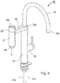
- FIG. 6 a water outlet fitting with an outlet for filtered water is shown, in which a filter cartridge according to the invention can be used as a filter insert.
- the water outlet fitting 20 shown comprises a fitting body 22 which is screwed onto a worktop or a kitchen sink.
- the water outlet 23 serves as an outlet for service water.
- service water is understood to mean hot water, cold water or mixed water, as it is obtained from the public water supply or an in-house water supply, but which has no or questionable drinking water quality.
- the water outlet fitting 20 has two supply lines 24a, 24b for hot water and cold water and a single-lever mixer 25 with a corresponding valve insert, with which the hot and cold water supplied can be mixed and output via the water outlet 23.
- a single-lever mixer 25 with which the hot and cold water supplied can be mixed and output via the water outlet 23.
- water paths thus lead in a manner which is also known per se from the supply lines 24a, 24b to the mixing valve 25 and from there to the water outlet 23.
- a second outlet line 26 branches off, at the end of which a filter housing 27 pointing vertically downwards is arranged.
- the outlet line 26 is designed in the form of an annular shoulder 26a, which lies concentrically around the upwardly pointing outlet line 23 and is pivotable about the central axis of the fitting body 22.
- a waterway for cold water runs on the inside of the fitting body 22 to the shoulder 26a and opens into an annular space formed inside the shoulder 26a, circumferentially open and sealed against the shoulder 26a, via which the water reaches the second outlet 26.
- the filter housing 27 is approximately cylindrical and converges conically towards its bottom 28. In the middle of this conical bottom area 8 there is an opening 28a, from which filtered drinking water can be dispensed.
- a valve 29 with a rotary handle 29a is arranged in the upper region of the filter housing 27. If this valve 29 is opened, so If water flows via the outlet line 26 into an outer ring area 27a of the filter housing 27, penetrates through the filter-active layers 4 of the filter cartridge 1 inserted in the filter housing 27 and is discharged axially via the mouthpiece 6.
- the filter housing 27 is shown enlarged in a longitudinal section.
- the filter cartridge 1 has the mouth piece 6, which is in the form of a downwardly pointing collar around the outlet opening of the axial interior space 5.
- the diameter of the opening 28a in the bottom 28 of the filter housing 27 is dimensioned such that the mouthpiece 6 fits through and is received by the opening 28a. Filtered water thus flows out through the mouthpiece 6 without coming into contact with the filter housing 27.
- the closing valve 29 can be seen with its valve handle 29a and a valve insert 29b located underneath.
- a spindle of the valve insert 29b is actuated and the valve 29 releases the water path coming from the outlet line 26 into the filter housing 27.
- valve insert 29b Between the valve insert 29b and the filter housing 27 there is also a check valve 30 with a closing body 30a, which is held in its open position upward by an actuating pin 31a.
- the confirmation pin 31a in turn is held upward by the filter cartridge 1 inserted into the filter housing 27, so that the check valve 30 is open when the filter cartridge 1 is inserted and the filter housing 27 is screwed on.
- a downwardly pointing receiving base 26b for the filter housing 27 is formed, on which the latter is fastened in a watertight manner by means of a screw or bayonet lock. If the filter housing 27 is removed in order to change the filter insert 1, the valve body 30a is moved downward into its closed position by the water pressure or alternatively a closing spring (not shown here) so that no water can escape from the outlet line 26.
- a battery-operated electrical circuit 33 is integrated into the valve cap 29a, which provides information about the state of the filter insert 1 via a multicolored light-emitting diode 34.
- the circuit 33 only contains a timer which is reset after the filter cartridge 1 has been replaced and which reminds the filter cartridge 1 to replace it after a preset operating time has elapsed.
- a flow meter arranged in the waterway, for example in the form of an impeller meter, so that an exchange of the filter cartridge 1 can be indicated depending on the amount of filtered water.
- the light-emitting diode 34 flashes green (e.g. every 5 seconds). After the intended period of use has expired, i.e. when an exchange of the filter cartridge 1 is recommended, the color of the light-emitting diode 34 changes to red. If the filter cartridge needs to be replaced and the drinking quality of the filter water is no longer guaranteed, the flashing frequency is also increased as a warning, e.g. rapid flashing 1x per second.
- the upper end face of the filter cartridge 1 is closed by its upper housing part 2.
- the confirmation pin 31a is supported on the upper side of the housing part 2 and is held by the latter in its upper position, in which it holds the check valve 30 in the open position.
- the seal 8 on the underside of the filter cartridge 1 seals the outer annular space 27a of the filter housing 27 towards the bottom 28 of the filter housing 27, so that water that has flown in from the outlet line 26 only enters the axial interior 5 of the filter insert after it has penetrated the filter-active layers 4 1 and can flow out from there through the mouth piece 6 attached to the filter insert.
Landscapes
- Chemical & Material Sciences (AREA)
- Engineering & Computer Science (AREA)
- Water Supply & Treatment (AREA)
- Life Sciences & Earth Sciences (AREA)
- Hydrology & Water Resources (AREA)
- Chemical Kinetics & Catalysis (AREA)
- Environmental & Geological Engineering (AREA)
- Organic Chemistry (AREA)
- Nanotechnology (AREA)
- Health & Medical Sciences (AREA)
- Public Health (AREA)
- Water Treatment By Sorption (AREA)
Priority Applications (1)
| Application Number | Priority Date | Filing Date | Title |
|---|---|---|---|
| PL19178127T PL3583992T3 (pl) | 2018-06-18 | 2019-06-04 | Wkład filtra do armatury wypływu wody z filtrem wody pitnej |
Applications Claiming Priority (1)
| Application Number | Priority Date | Filing Date | Title |
|---|---|---|---|
| DE102018114582.9A DE102018114582A1 (de) | 2018-06-18 | 2018-06-18 | Filtereinsatz für eine Wasserauslaufarmatur mit Trinkwasserfilter |
Publications (2)
| Publication Number | Publication Date |
|---|---|
| EP3583992A1 EP3583992A1 (de) | 2019-12-25 |
| EP3583992B1 true EP3583992B1 (de) | 2021-05-19 |
Family
ID=66752006
Family Applications (1)
| Application Number | Title | Priority Date | Filing Date |
|---|---|---|---|
| EP19178127.7A Active EP3583992B1 (de) | 2018-06-18 | 2019-06-04 | Filtereinsatz für eine wasserauslaufarmatur mit trinkwasserfilter |
Country Status (5)
| Country | Link |
|---|---|
| US (1) | US20190382287A1 (pl) |
| EP (1) | EP3583992B1 (pl) |
| CN (1) | CN211799293U (pl) |
| DE (1) | DE102018114582A1 (pl) |
| PL (1) | PL3583992T3 (pl) |
Families Citing this family (4)
| Publication number | Priority date | Publication date | Assignee | Title |
|---|---|---|---|---|
| USD991426S1 (en) * | 2020-12-24 | 2023-07-04 | Tianjin Yunda Industry and Trade Co., Ltd, Inc. | Filter cartridge |
| USD1035824S1 (en) * | 2021-11-30 | 2024-07-16 | 3Awater Oy | Holder for a water filter |
| USD1072163S1 (en) * | 2022-04-27 | 2025-04-22 | Wuhu TianHao E-commerce CO., LTD. | Fuel water separator |
| USD1065433S1 (en) * | 2023-09-25 | 2025-03-04 | WaterH Inc. | Water filter |
Family Cites Families (16)
| Publication number | Priority date | Publication date | Assignee | Title |
|---|---|---|---|---|
| FR1452754A (fr) * | 1965-07-30 | 1966-04-15 | Brise-jet filtre et aérateur | |
| WO1991010493A1 (en) * | 1990-01-16 | 1991-07-25 | Ametek, Inc.-Plymouth Products Division | Multi-function filter cartridge with flow distribution control |
| US5653868A (en) | 1994-04-06 | 1997-08-05 | Mitsubishi Rayon Company Ltd. | Diverter and water purifier having same |
| DE19618692C2 (de) * | 1996-05-09 | 1998-07-02 | Precision Sieves And Filters L | Filtervorrichtung für Wasser |
| US6096197A (en) | 1997-12-11 | 2000-08-01 | Hughes; Douglass E. | Shower filter for chlorine removal and scale deposit prevention |
| PL348456A1 (en) | 1998-01-21 | 2002-05-20 | Clorox Co | Faucet mounted water filter |
| US6251274B1 (en) * | 1999-03-16 | 2001-06-26 | Envirogard Products Limited | Faucet attachment for treating water |
| JP2002310357A (ja) | 2001-04-18 | 2002-10-23 | Toray Ind Inc | 自在継手および浄水器 |
| JP3906344B2 (ja) | 2001-05-09 | 2007-04-18 | 和歌山県 | 排水処理装置および排水処理方法 |
| BE1019019A3 (nl) | 2008-01-14 | 2012-01-10 | Jonghe Marc De | Een watervoorzieningseenheid voor het afleveren van gezuiverd water. |
| US7964099B2 (en) * | 2008-10-22 | 2011-06-21 | Te-Hsing Wang | Water filtering device |
| JP2012050904A (ja) | 2010-08-31 | 2012-03-15 | Panasonic Electric Works Co Ltd | 浄水カートリッジ、当該浄水カートリッジを備えた浄水装置および当該浄水装置を備えた流し台 |
| EP2476724A1 (en) | 2011-01-17 | 2012-07-18 | ETH Zurich | Pourous polymer membranes |
| BRPI1104487B1 (pt) | 2011-09-26 | 2020-12-01 | Duratex S.A | torneira misturadora com filtro |
| US9650767B2 (en) | 2013-02-01 | 2017-05-16 | Scott Anthony Nightlinger | Sink faucet assembly |
| CN204182216U (zh) * | 2014-11-06 | 2015-03-04 | 陈建光 | 一种家用水龙头净水器 |
-
2018
- 2018-06-18 DE DE102018114582.9A patent/DE102018114582A1/de not_active Ceased
-
2019
- 2019-06-04 EP EP19178127.7A patent/EP3583992B1/de active Active
- 2019-06-04 PL PL19178127T patent/PL3583992T3/pl unknown
- 2019-06-14 US US16/441,468 patent/US20190382287A1/en not_active Abandoned
- 2019-06-17 CN CN201920912408.4U patent/CN211799293U/zh active Active
Also Published As
| Publication number | Publication date |
|---|---|
| EP3583992A1 (de) | 2019-12-25 |
| CN211799293U (zh) | 2020-10-30 |
| US20190382287A1 (en) | 2019-12-19 |
| PL3583992T3 (pl) | 2021-10-18 |
| DE102018114582A1 (de) | 2019-12-19 |
Similar Documents
| Publication | Publication Date | Title |
|---|---|---|
| DE2640115C2 (de) | Vorrichtung zur Wasserreinigung | |
| DE69107023T2 (de) | Reiniger für Leitungswasser. | |
| EP0018527B1 (de) | Rückspülbare Filtereinrichtung, insbesondere für eine Hauswasseranlage | |
| EP3583992A1 (de) | Filtereinsatz für eine wasserauslaufarmatur mit trinkwasserfilter | |
| DE69624118T2 (de) | Dialysemaschine | |
| DE112010003584B4 (de) | Notfall-waschsystem | |
| DE3112037C2 (pl) | ||
| EP0253132A1 (de) | Filter zum Reinigen von Leitungswasser | |
| EP2108002A2 (de) | Wasserfiltervorrichtung mit stellorgan zur einstellung eines verschnittverhältnisses | |
| EP3583993B1 (de) | Wasserauslaufarmatur mit trinkwasserfilter | |
| DE202015106890U1 (de) | Rückspülfilter | |
| EP0341345B1 (de) | Ventil mit eingebautem Filtereinsatz | |
| EP2214837B1 (de) | Belüfungsanordnung für brausestrahlen | |
| DE10335343A1 (de) | Keramisches Filterelement zur Reinigung von Wasser | |
| DE2546881A1 (de) | Wasserfiltervorrichtung | |
| DE19648405A1 (de) | Anschlußeinheit für Großgeräte-Wasserfilter | |
| EP1576307B1 (de) | Sanitäre auslaufarmatur | |
| DE8916178U1 (de) | Wasseraustrittsarmatur | |
| DE102012107243B3 (de) | Sanitäres Wasserventil mit einem eine antibakterielle Beschichtung aufweisenden Auslaufteil | |
| DE19615102A1 (de) | Wasserreinigungsvorrichtung | |
| EP0668951A1 (de) | Siebanordnung zur erzeugung eines perlenden wasserstrahles | |
| DE202019005570U1 (de) | Flüssigkeitsreinigungsvorrichtung | |
| EP0284641B1 (de) | Vorrichtung zur Aufnahme und zum Trennen von insbesondere in Zahnarztpraxen anfallenden und im Bohrschlamm od.dgl. enthaltenen Schadstoffen aus Metallverbindungen enthaltenden Zahnfüllmaterialien | |
| DE102009042143A1 (de) | Filteranordnung zur Verwendung in einem Druckregler für eine landwirtschaftliche Austragvorrichtung | |
| WO2023213606A1 (de) | Gekapselte multistufen-filterpatrone für trinkwasserbereitstellungs-vorrichtung und zugehörige trinkwasserbereitstellungs-vorrichtung |
Legal Events
| Date | Code | Title | Description |
|---|---|---|---|
| PUAI | Public reference made under article 153(3) epc to a published international application that has entered the european phase |
Free format text: ORIGINAL CODE: 0009012 |
|
| STAA | Information on the status of an ep patent application or granted ep patent |
Free format text: STATUS: THE APPLICATION HAS BEEN PUBLISHED |
|
| AK | Designated contracting states |
Kind code of ref document: A1 Designated state(s): AL AT BE BG CH CY CZ DE DK EE ES FI FR GB GR HR HU IE IS IT LI LT LU LV MC MK MT NL NO PL PT RO RS SE SI SK SM TR |
|
| AX | Request for extension of the european patent |
Extension state: BA ME |
|
| STAA | Information on the status of an ep patent application or granted ep patent |
Free format text: STATUS: REQUEST FOR EXAMINATION WAS MADE |
|
| 17P | Request for examination filed |
Effective date: 20200512 |
|
| RBV | Designated contracting states (corrected) |
Designated state(s): AL AT BE BG CH CY CZ DE DK EE ES FI FR GB GR HR HU IE IS IT LI LT LU LV MC MK MT NL NO PL PT RO RS SE SI SK SM TR |
|
| GRAP | Despatch of communication of intention to grant a patent |
Free format text: ORIGINAL CODE: EPIDOSNIGR1 |
|
| STAA | Information on the status of an ep patent application or granted ep patent |
Free format text: STATUS: GRANT OF PATENT IS INTENDED |
|
| RIC1 | Information provided on ipc code assigned before grant |
Ipc: E03C 1/08 20060101ALI20201214BHEP Ipc: B01D 35/04 20060101AFI20201214BHEP |
|
| INTG | Intention to grant announced |
Effective date: 20210114 |
|
| RIN1 | Information on inventor provided before grant (corrected) |
Inventor name: LEUTWILER, MARKUS Inventor name: LOEPFE, MICHAEL Inventor name: KELLENBERGER, CHRISTOPH Inventor name: RUEEGG, ANDREAS |
|
| GRAS | Grant fee paid |
Free format text: ORIGINAL CODE: EPIDOSNIGR3 |
|
| GRAA | (expected) grant |
Free format text: ORIGINAL CODE: 0009210 |
|
| STAA | Information on the status of an ep patent application or granted ep patent |
Free format text: STATUS: THE PATENT HAS BEEN GRANTED |
|
| AK | Designated contracting states |
Kind code of ref document: B1 Designated state(s): AL AT BE BG CH CY CZ DE DK EE ES FI FR GB GR HR HU IE IS IT LI LT LU LV MC MK MT NL NO PL PT RO RS SE SI SK SM TR |
|
| REG | Reference to a national code |
Ref country code: GB Ref legal event code: FG4D Free format text: NOT ENGLISH |
|
| REG | Reference to a national code |
Ref country code: CH Ref legal event code: EP |
|
| REG | Reference to a national code |
Ref country code: DE Ref legal event code: R096 Ref document number: 502019001441 Country of ref document: DE |
|
| REG | Reference to a national code |
Ref country code: AT Ref legal event code: REF Ref document number: 1393442 Country of ref document: AT Kind code of ref document: T Effective date: 20210615 |
|
| REG | Reference to a national code |
Ref country code: IE Ref legal event code: FG4D Free format text: LANGUAGE OF EP DOCUMENT: GERMAN |
|
| REG | Reference to a national code |
Ref country code: GR Ref legal event code: EP Ref document number: 20210401523 Country of ref document: GR Effective date: 20210709 |
|
| REG | Reference to a national code |
Ref country code: LT Ref legal event code: MG9D |
|
| REG | Reference to a national code |
Ref country code: NL Ref legal event code: MP Effective date: 20210519 |
|
| PG25 | Lapsed in a contracting state [announced via postgrant information from national office to epo] |
Ref country code: FI Free format text: LAPSE BECAUSE OF FAILURE TO SUBMIT A TRANSLATION OF THE DESCRIPTION OR TO PAY THE FEE WITHIN THE PRESCRIBED TIME-LIMIT Effective date: 20210519 Ref country code: HR Free format text: LAPSE BECAUSE OF FAILURE TO SUBMIT A TRANSLATION OF THE DESCRIPTION OR TO PAY THE FEE WITHIN THE PRESCRIBED TIME-LIMIT Effective date: 20210519 Ref country code: LT Free format text: LAPSE BECAUSE OF FAILURE TO SUBMIT A TRANSLATION OF THE DESCRIPTION OR TO PAY THE FEE WITHIN THE PRESCRIBED TIME-LIMIT Effective date: 20210519 Ref country code: BG Free format text: LAPSE BECAUSE OF FAILURE TO SUBMIT A TRANSLATION OF THE DESCRIPTION OR TO PAY THE FEE WITHIN THE PRESCRIBED TIME-LIMIT Effective date: 20210819 |
|
| PG25 | Lapsed in a contracting state [announced via postgrant information from national office to epo] |
Ref country code: LV Free format text: LAPSE BECAUSE OF FAILURE TO SUBMIT A TRANSLATION OF THE DESCRIPTION OR TO PAY THE FEE WITHIN THE PRESCRIBED TIME-LIMIT Effective date: 20210519 Ref country code: NO Free format text: LAPSE BECAUSE OF FAILURE TO SUBMIT A TRANSLATION OF THE DESCRIPTION OR TO PAY THE FEE WITHIN THE PRESCRIBED TIME-LIMIT Effective date: 20210819 Ref country code: RS Free format text: LAPSE BECAUSE OF FAILURE TO SUBMIT A TRANSLATION OF THE DESCRIPTION OR TO PAY THE FEE WITHIN THE PRESCRIBED TIME-LIMIT Effective date: 20210519 Ref country code: SE Free format text: LAPSE BECAUSE OF FAILURE TO SUBMIT A TRANSLATION OF THE DESCRIPTION OR TO PAY THE FEE WITHIN THE PRESCRIBED TIME-LIMIT Effective date: 20210519 Ref country code: PT Free format text: LAPSE BECAUSE OF FAILURE TO SUBMIT A TRANSLATION OF THE DESCRIPTION OR TO PAY THE FEE WITHIN THE PRESCRIBED TIME-LIMIT Effective date: 20210920 Ref country code: IS Free format text: LAPSE BECAUSE OF FAILURE TO SUBMIT A TRANSLATION OF THE DESCRIPTION OR TO PAY THE FEE WITHIN THE PRESCRIBED TIME-LIMIT Effective date: 20210919 |
|
| PG25 | Lapsed in a contracting state [announced via postgrant information from national office to epo] |
Ref country code: NL Free format text: LAPSE BECAUSE OF FAILURE TO SUBMIT A TRANSLATION OF THE DESCRIPTION OR TO PAY THE FEE WITHIN THE PRESCRIBED TIME-LIMIT Effective date: 20210519 |
|
| PG25 | Lapsed in a contracting state [announced via postgrant information from national office to epo] |
Ref country code: EE Free format text: LAPSE BECAUSE OF FAILURE TO SUBMIT A TRANSLATION OF THE DESCRIPTION OR TO PAY THE FEE WITHIN THE PRESCRIBED TIME-LIMIT Effective date: 20210519 Ref country code: ES Free format text: LAPSE BECAUSE OF FAILURE TO SUBMIT A TRANSLATION OF THE DESCRIPTION OR TO PAY THE FEE WITHIN THE PRESCRIBED TIME-LIMIT Effective date: 20210519 Ref country code: SK Free format text: LAPSE BECAUSE OF FAILURE TO SUBMIT A TRANSLATION OF THE DESCRIPTION OR TO PAY THE FEE WITHIN THE PRESCRIBED TIME-LIMIT Effective date: 20210519 Ref country code: SM Free format text: LAPSE BECAUSE OF FAILURE TO SUBMIT A TRANSLATION OF THE DESCRIPTION OR TO PAY THE FEE WITHIN THE PRESCRIBED TIME-LIMIT Effective date: 20210519 Ref country code: RO Free format text: LAPSE BECAUSE OF FAILURE TO SUBMIT A TRANSLATION OF THE DESCRIPTION OR TO PAY THE FEE WITHIN THE PRESCRIBED TIME-LIMIT Effective date: 20210519 Ref country code: DK Free format text: LAPSE BECAUSE OF FAILURE TO SUBMIT A TRANSLATION OF THE DESCRIPTION OR TO PAY THE FEE WITHIN THE PRESCRIBED TIME-LIMIT Effective date: 20210519 Ref country code: CZ Free format text: LAPSE BECAUSE OF FAILURE TO SUBMIT A TRANSLATION OF THE DESCRIPTION OR TO PAY THE FEE WITHIN THE PRESCRIBED TIME-LIMIT Effective date: 20210519 |
|
| REG | Reference to a national code |
Ref country code: DE Ref legal event code: R097 Ref document number: 502019001441 Country of ref document: DE |
|
| REG | Reference to a national code |
Ref country code: BE Ref legal event code: MM Effective date: 20210630 |
|
| PLBE | No opposition filed within time limit |
Free format text: ORIGINAL CODE: 0009261 |
|
| STAA | Information on the status of an ep patent application or granted ep patent |
Free format text: STATUS: NO OPPOSITION FILED WITHIN TIME LIMIT |
|
| PG25 | Lapsed in a contracting state [announced via postgrant information from national office to epo] |
Ref country code: MC Free format text: LAPSE BECAUSE OF FAILURE TO SUBMIT A TRANSLATION OF THE DESCRIPTION OR TO PAY THE FEE WITHIN THE PRESCRIBED TIME-LIMIT Effective date: 20210519 Ref country code: LU Free format text: LAPSE BECAUSE OF NON-PAYMENT OF DUE FEES Effective date: 20210604 |
|
| 26N | No opposition filed |
Effective date: 20220222 |
|
| PG25 | Lapsed in a contracting state [announced via postgrant information from national office to epo] |
Ref country code: IE Free format text: LAPSE BECAUSE OF NON-PAYMENT OF DUE FEES Effective date: 20210604 |
|
| PG25 | Lapsed in a contracting state [announced via postgrant information from national office to epo] |
Ref country code: IS Free format text: LAPSE BECAUSE OF FAILURE TO SUBMIT A TRANSLATION OF THE DESCRIPTION OR TO PAY THE FEE WITHIN THE PRESCRIBED TIME-LIMIT Effective date: 20210919 Ref country code: FR Free format text: LAPSE BECAUSE OF NON-PAYMENT OF DUE FEES Effective date: 20210719 Ref country code: AL Free format text: LAPSE BECAUSE OF FAILURE TO SUBMIT A TRANSLATION OF THE DESCRIPTION OR TO PAY THE FEE WITHIN THE PRESCRIBED TIME-LIMIT Effective date: 20210519 |
|
| PG25 | Lapsed in a contracting state [announced via postgrant information from national office to epo] |
Ref country code: BE Free format text: LAPSE BECAUSE OF NON-PAYMENT OF DUE FEES Effective date: 20210630 |
|
| PG25 | Lapsed in a contracting state [announced via postgrant information from national office to epo] |
Ref country code: CY Free format text: LAPSE BECAUSE OF FAILURE TO SUBMIT A TRANSLATION OF THE DESCRIPTION OR TO PAY THE FEE WITHIN THE PRESCRIBED TIME-LIMIT Effective date: 20210519 |
|
| P01 | Opt-out of the competence of the unified patent court (upc) registered |
Effective date: 20230602 |
|
| PG25 | Lapsed in a contracting state [announced via postgrant information from national office to epo] |
Ref country code: HU Free format text: LAPSE BECAUSE OF FAILURE TO SUBMIT A TRANSLATION OF THE DESCRIPTION OR TO PAY THE FEE WITHIN THE PRESCRIBED TIME-LIMIT; INVALID AB INITIO Effective date: 20190604 |
|
| PG25 | Lapsed in a contracting state [announced via postgrant information from national office to epo] |
Ref country code: MK Free format text: LAPSE BECAUSE OF FAILURE TO SUBMIT A TRANSLATION OF THE DESCRIPTION OR TO PAY THE FEE WITHIN THE PRESCRIBED TIME-LIMIT Effective date: 20210519 |
|
| PG25 | Lapsed in a contracting state [announced via postgrant information from national office to epo] |
Ref country code: MT Free format text: LAPSE BECAUSE OF FAILURE TO SUBMIT A TRANSLATION OF THE DESCRIPTION OR TO PAY THE FEE WITHIN THE PRESCRIBED TIME-LIMIT Effective date: 20210519 |
|
| PGFP | Annual fee paid to national office [announced via postgrant information from national office to epo] |
Ref country code: PL Payment date: 20250527 Year of fee payment: 7 Ref country code: DE Payment date: 20250604 Year of fee payment: 7 |
|
| PGFP | Annual fee paid to national office [announced via postgrant information from national office to epo] |
Ref country code: GB Payment date: 20250620 Year of fee payment: 7 |
|
| PGFP | Annual fee paid to national office [announced via postgrant information from national office to epo] |
Ref country code: GR Payment date: 20250616 Year of fee payment: 7 |
|
| PGFP | Annual fee paid to national office [announced via postgrant information from national office to epo] |
Ref country code: AT Payment date: 20250616 Year of fee payment: 7 |
|
| PGFP | Annual fee paid to national office [announced via postgrant information from national office to epo] |
Ref country code: IT Payment date: 20250630 Year of fee payment: 7 |
|
| PGFP | Annual fee paid to national office [announced via postgrant information from national office to epo] |
Ref country code: CH Payment date: 20250701 Year of fee payment: 7 |
|
| PG25 | Lapsed in a contracting state [announced via postgrant information from national office to epo] |
Ref country code: TR Free format text: LAPSE BECAUSE OF FAILURE TO SUBMIT A TRANSLATION OF THE DESCRIPTION OR TO PAY THE FEE WITHIN THE PRESCRIBED TIME-LIMIT Effective date: 20210519 |