EP3582289B1 - Batteriepack und elektrisches fahrzeug - Google Patents
Batteriepack und elektrisches fahrzeug Download PDFInfo
- Publication number
- EP3582289B1 EP3582289B1 EP19176979.3A EP19176979A EP3582289B1 EP 3582289 B1 EP3582289 B1 EP 3582289B1 EP 19176979 A EP19176979 A EP 19176979A EP 3582289 B1 EP3582289 B1 EP 3582289B1
- Authority
- EP
- European Patent Office
- Prior art keywords
- heat exchanging
- exchanging plate
- battery pack
- longitudinal beam
- plate
- Prior art date
- Legal status (The legal status is an assumption and is not a legal conclusion. Google has not performed a legal analysis and makes no representation as to the accuracy of the status listed.)
- Active
Links
Images



Classifications
-
- H—ELECTRICITY
- H01—ELECTRIC ELEMENTS
- H01M—PROCESSES OR MEANS, e.g. BATTERIES, FOR THE DIRECT CONVERSION OF CHEMICAL ENERGY INTO ELECTRICAL ENERGY
- H01M10/00—Secondary cells; Manufacture thereof
- H01M10/60—Heating or cooling; Temperature control
- H01M10/62—Heating or cooling; Temperature control specially adapted for specific applications
- H01M10/625—Vehicles
-
- B—PERFORMING OPERATIONS; TRANSPORTING
- B60—VEHICLES IN GENERAL
- B60K—ARRANGEMENT OR MOUNTING OF PROPULSION UNITS OR OF TRANSMISSIONS IN VEHICLES; ARRANGEMENT OR MOUNTING OF PLURAL DIVERSE PRIME-MOVERS IN VEHICLES; AUXILIARY DRIVES FOR VEHICLES; INSTRUMENTATION OR DASHBOARDS FOR VEHICLES; ARRANGEMENTS IN CONNECTION WITH COOLING, AIR INTAKE, GAS EXHAUST OR FUEL SUPPLY OF PROPULSION UNITS IN VEHICLES
- B60K1/00—Arrangement or mounting of electrical propulsion units
- B60K1/04—Arrangement or mounting of electrical propulsion units of the electric storage means for propulsion
-
- B—PERFORMING OPERATIONS; TRANSPORTING
- B60—VEHICLES IN GENERAL
- B60L—PROPULSION OF ELECTRICALLY-PROPELLED VEHICLES; SUPPLYING ELECTRIC POWER FOR AUXILIARY EQUIPMENT OF ELECTRICALLY-PROPELLED VEHICLES; ELECTRODYNAMIC BRAKE SYSTEMS FOR VEHICLES IN GENERAL; MAGNETIC SUSPENSION OR LEVITATION FOR VEHICLES; MONITORING OPERATING VARIABLES OF ELECTRICALLY-PROPELLED VEHICLES; ELECTRIC SAFETY DEVICES FOR ELECTRICALLY-PROPELLED VEHICLES
- B60L50/00—Electric propulsion with power supplied within the vehicle
- B60L50/50—Electric propulsion with power supplied within the vehicle using propulsion power supplied by batteries or fuel cells
- B60L50/60—Electric propulsion with power supplied within the vehicle using propulsion power supplied by batteries or fuel cells using power supplied by batteries
- B60L50/64—Constructional details of batteries specially adapted for electric vehicles
-
- B—PERFORMING OPERATIONS; TRANSPORTING
- B60—VEHICLES IN GENERAL
- B60L—PROPULSION OF ELECTRICALLY-PROPELLED VEHICLES; SUPPLYING ELECTRIC POWER FOR AUXILIARY EQUIPMENT OF ELECTRICALLY-PROPELLED VEHICLES; ELECTRODYNAMIC BRAKE SYSTEMS FOR VEHICLES IN GENERAL; MAGNETIC SUSPENSION OR LEVITATION FOR VEHICLES; MONITORING OPERATING VARIABLES OF ELECTRICALLY-PROPELLED VEHICLES; ELECTRIC SAFETY DEVICES FOR ELECTRICALLY-PROPELLED VEHICLES
- B60L50/00—Electric propulsion with power supplied within the vehicle
- B60L50/50—Electric propulsion with power supplied within the vehicle using propulsion power supplied by batteries or fuel cells
- B60L50/60—Electric propulsion with power supplied within the vehicle using propulsion power supplied by batteries or fuel cells using power supplied by batteries
- B60L50/66—Arrangements of batteries
-
- H—ELECTRICITY
- H01—ELECTRIC ELEMENTS
- H01M—PROCESSES OR MEANS, e.g. BATTERIES, FOR THE DIRECT CONVERSION OF CHEMICAL ENERGY INTO ELECTRICAL ENERGY
- H01M10/00—Secondary cells; Manufacture thereof
- H01M10/05—Accumulators with non-aqueous electrolyte
- H01M10/052—Li-accumulators
- H01M10/0525—Rocking-chair batteries, i.e. batteries with lithium insertion or intercalation in both electrodes; Lithium-ion batteries
-
- H—ELECTRICITY
- H01—ELECTRIC ELEMENTS
- H01M—PROCESSES OR MEANS, e.g. BATTERIES, FOR THE DIRECT CONVERSION OF CHEMICAL ENERGY INTO ELECTRICAL ENERGY
- H01M10/00—Secondary cells; Manufacture thereof
- H01M10/60—Heating or cooling; Temperature control
- H01M10/61—Types of temperature control
- H01M10/613—Cooling or keeping cold
-
- H—ELECTRICITY
- H01—ELECTRIC ELEMENTS
- H01M—PROCESSES OR MEANS, e.g. BATTERIES, FOR THE DIRECT CONVERSION OF CHEMICAL ENERGY INTO ELECTRICAL ENERGY
- H01M10/00—Secondary cells; Manufacture thereof
- H01M10/60—Heating or cooling; Temperature control
- H01M10/61—Types of temperature control
- H01M10/615—Heating or keeping warm
-
- H—ELECTRICITY
- H01—ELECTRIC ELEMENTS
- H01M—PROCESSES OR MEANS, e.g. BATTERIES, FOR THE DIRECT CONVERSION OF CHEMICAL ENERGY INTO ELECTRICAL ENERGY
- H01M10/00—Secondary cells; Manufacture thereof
- H01M10/60—Heating or cooling; Temperature control
- H01M10/65—Means for temperature control structurally associated with the cells
- H01M10/655—Solid structures for heat exchange or heat conduction
- H01M10/6554—Rods or plates
-
- H—ELECTRICITY
- H01—ELECTRIC ELEMENTS
- H01M—PROCESSES OR MEANS, e.g. BATTERIES, FOR THE DIRECT CONVERSION OF CHEMICAL ENERGY INTO ELECTRICAL ENERGY
- H01M50/00—Constructional details or processes of manufacture of the non-active parts of electrochemical cells other than fuel cells, e.g. hybrid cells
- H01M50/20—Mountings; Secondary casings or frames; Racks, modules or packs; Suspension devices; Shock absorbers; Transport or carrying devices; Holders
- H01M50/244—Secondary casings; Racks; Suspension devices; Carrying devices; Holders characterised by their mounting method
-
- H—ELECTRICITY
- H01—ELECTRIC ELEMENTS
- H01M—PROCESSES OR MEANS, e.g. BATTERIES, FOR THE DIRECT CONVERSION OF CHEMICAL ENERGY INTO ELECTRICAL ENERGY
- H01M50/00—Constructional details or processes of manufacture of the non-active parts of electrochemical cells other than fuel cells, e.g. hybrid cells
- H01M50/20—Mountings; Secondary casings or frames; Racks, modules or packs; Suspension devices; Shock absorbers; Transport or carrying devices; Holders
- H01M50/249—Mountings; Secondary casings or frames; Racks, modules or packs; Suspension devices; Shock absorbers; Transport or carrying devices; Holders specially adapted for aircraft or vehicles, e.g. cars or trains
-
- H—ELECTRICITY
- H01—ELECTRIC ELEMENTS
- H01M—PROCESSES OR MEANS, e.g. BATTERIES, FOR THE DIRECT CONVERSION OF CHEMICAL ENERGY INTO ELECTRICAL ENERGY
- H01M50/00—Constructional details or processes of manufacture of the non-active parts of electrochemical cells other than fuel cells, e.g. hybrid cells
- H01M50/20—Mountings; Secondary casings or frames; Racks, modules or packs; Suspension devices; Shock absorbers; Transport or carrying devices; Holders
- H01M50/262—Mountings; Secondary casings or frames; Racks, modules or packs; Suspension devices; Shock absorbers; Transport or carrying devices; Holders with fastening means, e.g. locks
-
- H—ELECTRICITY
- H01—ELECTRIC ELEMENTS
- H01M—PROCESSES OR MEANS, e.g. BATTERIES, FOR THE DIRECT CONVERSION OF CHEMICAL ENERGY INTO ELECTRICAL ENERGY
- H01M2220/00—Batteries for particular applications
- H01M2220/20—Batteries in motive systems, e.g. vehicle, ship, plane
-
- Y—GENERAL TAGGING OF NEW TECHNOLOGICAL DEVELOPMENTS; GENERAL TAGGING OF CROSS-SECTIONAL TECHNOLOGIES SPANNING OVER SEVERAL SECTIONS OF THE IPC; TECHNICAL SUBJECTS COVERED BY FORMER USPC CROSS-REFERENCE ART COLLECTIONS [XRACs] AND DIGESTS
- Y02—TECHNOLOGIES OR APPLICATIONS FOR MITIGATION OR ADAPTATION AGAINST CLIMATE CHANGE
- Y02E—REDUCTION OF GREENHOUSE GAS [GHG] EMISSIONS, RELATED TO ENERGY GENERATION, TRANSMISSION OR DISTRIBUTION
- Y02E60/00—Enabling technologies; Technologies with a potential or indirect contribution to GHG emissions mitigation
- Y02E60/10—Energy storage using batteries
-
- Y—GENERAL TAGGING OF NEW TECHNOLOGICAL DEVELOPMENTS; GENERAL TAGGING OF CROSS-SECTIONAL TECHNOLOGIES SPANNING OVER SEVERAL SECTIONS OF THE IPC; TECHNICAL SUBJECTS COVERED BY FORMER USPC CROSS-REFERENCE ART COLLECTIONS [XRACs] AND DIGESTS
- Y02—TECHNOLOGIES OR APPLICATIONS FOR MITIGATION OR ADAPTATION AGAINST CLIMATE CHANGE
- Y02T—CLIMATE CHANGE MITIGATION TECHNOLOGIES RELATED TO TRANSPORTATION
- Y02T10/00—Road transport of goods or passengers
- Y02T10/60—Other road transportation technologies with climate change mitigation effect
- Y02T10/70—Energy storage systems for electromobility, e.g. batteries
Definitions
- the present invention relates to the field of battery, and particularly relates to a battery pack and electric automobile.
- the features of the preamble of the independent claim are known from CN 106 025 132 A and US 9 533 600 B1 .
- Related technologies are known from US 2017/047623 A1 , CN 206 878 068 U and US 2016/141735 A1 .
- the normal ideal operating temperature of the battery is 20°C ⁇ 35°C, and in order to ensure the normal service life of the battery in extremely cold environment or in extremely hot environment, thermal management is necessarily designed for the battery pack and adjusts the operating temperature of the battery by heating or cooling.
- the existing structure of the battery pack needs to be redesigned, and because the interior space of the box is relatively limited, which causes great difficulty on the design.
- the heat exchanging liquid in the heat exchanging plate of the battery pack leaks out in the process of long-term service, on one hand, the heat exchanging liquid will makes the outer case of the battery be electrically conducted with the metal component of the box, thereby lowering the insulation resistance value of the entire box, on the other hand, the heat exchanging liquid also can accelerate the corrosion process of the metal component of the box, thereby generating safety hazard.
- the heat exchanging plate of the battery pack will directly contact a mounting plate of the electric automobile. Because the temperature of the mounting plate is close to the temperature of the external environment of the electric automobile, when the electric automobile is in extremely cold environment or extremely hot environment, the mounting plate will exchange heat with the heat exchanging plate, thereby lowering the cooling or heating efficiency of the heat exchanging plate with respect to the battery inside the box.
- an object of the present invention is to provide a battery pack and electric automobile, a bracket assembly of the battery pack interposes between the heat exchanging plate and the mounting plate of the electric automobile, which reduces the effect of the temperature of the mounting plate on the heat exchanging plate, thereby improving the cooling or heating efficiency of the heat exchanging plate.
- the present invention is defined in the independent claim.
- the present invention provides a battery pack, which is used for an electric automobile and comprises: a box; a heat exchanging plate positioned below the box in a height direction; and a bracket assembly positioned below the heat exchanging plate in the height direction and fixedly connected with the box, and the bracket assembly is used to directly contact a mounting plate of the electric automobile.
- the bracket assembly comprises: at least two longitudinal beams spaced apart from each other in a width direction; and at least two transversal beams spaced apart from each other in a length direction, and two transversal beam end portions of the transversal beam in the width direction each are fixedly connected with one corresponding longitudinal beam.
- the heat exchanging plate comprises: a main body portion; and a plurality of first mounting portions, each first mounting portion is formed to protrude from the main body portion.
- the longitudinal beam comprises: a plurality of second mounting portions formed on one side of the longitudinal beam facing the heat exchanging plate, each second mounting portion is cooperated with and fixedly connected with one corresponding first mounting portion of the heat exchanging plate.
- the heat exchanging plate further comprises: a plurality of first fitting portions formed on one side of the heat exchanging plate facing the bracket assembly and spaced apart from each other in the width direction.
- the transversal beam further comprises: a plurality of second fitting portions formed on one side of the transversal beam facing the heat exchanging plate and spaced apart from each other in the width direction, and each second fitting portion is fitted with one corresponding first fitting portion by concave-convex fit.
- the first fitting portion of the heat exchanging plate is formed in a U-shaped structure.
- the plurality of second fitting portions of the transversal beam are formed as a saw-toothed structure.
- the longitudinal beam further comprises: a plurality of third mounting portions formed on one side of the longitudinal beam facing the heat exchanging plate and spaced apart from each other in the length direction, and each third mounting portion is fixedly connected with one transversal beam end portion of the corresponding transversal beam.
- the bracket assembly further comprises: a protecting beam fixedly connected with the longitudinal beam end portion of the longitudinal beam in the length direction, and the protecting beam is used for protecting the heat exchanging plate in the length direction.
- the longitudinal beam further comprises: a fourth mounting portion formed on one side of the longitudinal beam end portion facing the heat exchanging plate and fixedly connected with the protecting beam.
- the protecting beam comprises: a flat plate portion arranged side by side with the at least two transversal beam; and a side plate portion protruding from the flat plate portion in the height direction and positioned at one side of the heat exchanging plate in the length direction to protect the heat exchanging plate in the length direction.
- the longitudinal beam further comprises: a supporting portion formed on one side of the longitudinal beam in the width direction and extending in the width direction; and an installing portion formed on the other side of the longitudinal beam in the width direction and extending in the width direction.
- the present invention further provides an electric automobile, which comprises the battery pack described above.
- the present invention has the following beneficial effects: because the bracket assembly of the battery pack interposes between the heat exchanging plate and the mounting plate, the heat exchanging plate does not need to be directly exchanged heat with the mounting plate, thereby lowering the effect of temperature of the mounting plate on the heat exchanging plate, and improving the cooling or heating efficiency of the battery inside the box by the heat exchanging plate.
- an electric automobile according to the present invention comprises a mounting plate (not shown) and a battery pack.
- the mounting plate is used to mount the battery pack and directly contact the battery pack.
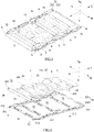
- the battery pack comprises: a box 1 accommodating a battery (not shown); a heat exchanging plate 2 positioned below the box 1 in a height direction H; and a bracket assembly 3 positioned below the heat exchanging plate 2 in the height direction H and fixedly connected with the box 1, and the bracket assembly 3 is used to directly contact the mounting plate. Because the bracket assembly 3 of the battery pack interposes between the heat exchanging plate 2 and the mounting plate, the heat exchanging plate 2 does not need to be directly exchanged heat with the mounting plate, thereby lowering the effect of temperature of the mounting plate on the heat exchanging plate 2 (especially when the electric automobile is in extremely cold environment or extremely hot environment), and improving the cooling or heating efficiency of the battery inside the box 1 by the heat exchanging plate 2.
- the box 1, the heat exchanging plate 2 and the bracket assembly 3 are independent components, when the heat exchanging plate 2 is in failure, the heat exchanging plate 2 can be replaced at any time.
- the heat exchanging plate 2 In the process of use of the battery pack, in order to adjust the operating temperature of the battery by the heat exchanging plate 2, the heat exchanging plate 2 generally comprises a heat exchanging liquid circulating therein, and it can adopt a method of heating or stopping to heat the heat exchanging liquid so as to adjust the operating temperature of the battery, or a method of providing a heating film sheet on the heat exchanging plate 2 to adjust the operating temperature of the battery.
- a plurality of seventh mounting holes 11 are provided on an exterior of the box 1 of the battery pack, and the bracket assembly 3 is fixedly connected with the box 1 by the plurality of seventh mounting holes 11 of the box 1 and fasteners S.
- the bracket assembly 3 may comprise: at least two longitudinal beams 31 spaced apart from each other in a width direction W; and at least two transversal beams 32 spaced apart from each other in a length direction L, and two transversal beam end portions 321 of the transversal beam 32 in the width direction W each are fixedly connected with one corresponding longitudinal beam 31.
- the longitudinal beam 31 and the transversal beam 32 may be made of a metal material, such as stainless steel, aluminum or aluminum alloy and the like.
- the bracket assembly 3 is formed as a frame structure by interconnecting the at least two longitudinal beams 31 and the at least two transversal beams 32, and such a structure of the bracket assembly 3 forms a space for air flowing between the heat exchanging plate 2 and the mounting plate. Because the thermal conductivity of the air is low, it may further reduce the heat transfer efficiency of the mounting plate toward the heat exchanging plate 2, and decrease the effect of the temperature of the mounting plate on the temperature of the heat exchanging liquid in the heat exchanging plate 2, thereby assisting to improve the heat exchanging or heating efficiency of the heat exchanging plate 2 with respect to the battery. Moreover, such a frame structure has strong load-carrying capability and strong anti-impact capability, and improves the structural strength of the entire battery pack.
- the bracket assembly 3 can directly bear impact or collision with respect to the heat exchanging plate 2 from an external object (including the mounting plate), thereby avoiding the damage of the heat exchanging plate 2 by the external force, and thus the bracket assembly 3 provides a good protection for the heat exchanging plate 2.
- the frame structure also assists to save material and greatly reduce cost.
- the longitudinal beam 31 may be provided as two in number. However, it is not limited thereto, and in order to further enhance the entire strength of the bracket assembly 3, the number of the longitudinal beams 31 may be appropriately increased.
- the bracket assembly 3 supports and fixedly installs the heat exchanging plate 2 from below the heat exchanging plate 2.
- the heat exchanging plate 2 may comprise: a main body portion 21; and a plurality of first mounting portions 22, each first mounting portion 22 is formed to protrude from the main body portion 21.
- the longitudinal beam 31 may comprise a plurality of second mounting portions 312 formed on one side of the longitudinal beam 31 facing the heat exchanging plate 2, each second mounting portion 312 is cooperated with and fixedly connected with one corresponding first mounting portion 22 of the heat exchanging plate 2.
- the second mounting portion 312 of the longitudinal beam 31 may be cooperated with the corresponding first mounting portion 22 by concave-convex fit.
- the second mounting portion 312 may be a protrusion
- the corresponding first mounting portion 22 is a recessed groove.
- the second mounting portion 312 may be a recessed groove (as shown in FIG. 4 and FIG. 6 )
- the corresponding first mounting portion 22 is a protrusion (as shown in FIG. 4 and FIG. 5 ).
- the first mounting portions 22 may be formed on two sides of the main body portion 21 in the width direction W, and the first mounting portions 22 protrude from the first mounting portion 22 in the width direction W, and the first mounting portions 22 positioned on the same side of the main body portion 21 in the width direction are spaced apart from each other.
- the heat exchanging plate 2 may further comprise: a extending portion 24 formed on one side of the main body portion 21 in the length direction L and protruding from the main body portion 21 in the width direction W.
- the first mounting portions 22 may be respectively formed on two ends of the extending portion 24 in the width direction W, and the first mounting portions 22 protrude from the extending portion 24 in the length direction L, and the second mounting portion 312 cooperated with the first mounting portion 22 on the extending portion 24 is formed on the longitudinal beam end portion 311 of the longitudinal beam 31.
- the plurality of the first mounting portions 22 of the heat exchanging plate 2 may be fixedly connected with the corresponding second mounting portions 312 of the longitudinal beams 31 of the bracket assembly 3 by the fasteners S.
- the first mounting portion 22 of the heat exchanging plate 2 may be provided with a first mounting hole 221.
- the second mounting portion 312 of the longitudinal beam 31 may be provided with a second mounting hole 3121.
- the first mounting hole 221 of the heat exchanging plate 2 and the corresponding second mounting hole 3121 of the longitudinal beam 31 are aligned with each other in the height direction H and allow the corresponding fastener S to pass through and fixedly connect the heat exchanging plate 2 with the longitudinal beam 31.
- the second mounting hole 3121 of the bracket assembly 3 In order to ensure the connection reliability between the heat exchanging plate 2 and the box 1, the second mounting hole 3121 of the bracket assembly 3, the first mounting hole 221 of the heat exchanging plate 2 and the seventh mounting hole 11 of the box 1 which correspond to each other are fixedly connected together by the fastener S.
- the heat exchanging plate 2 may be fixedly connected with the transversal beam 32 of the bracket assembly 3 by concave-convex fit, thereby assisting to assemble the heat exchanging plate 2 and the bracket assembly 3 quickly.
- the heat exchanging plate 2 may further comprise a plurality of first fitting portions 23 formed on one side of the heat exchanging plate 2 facing the bracket assembly 3 and spaced apart from each other in the width direction W. Referring to FIG. 4 , FIG. 8 and FIG.
- the transversal beam 32 may further comprise a plurality of second fitting portions 322 formed on one side of the transversal beam 32 facing the heat exchanging plate 2 and spaced apart from each other in the width direction W, and each second fitting portion 322 is fitted with one corresponding first fitting portion 23 by concave-convex fit.
- the first fitting portion 23 of the heat exchanging plate 2 may be a protrusion, correspondingly, the second fitting portion 322 of the transversal beam 32 is a recessed groove.
- the first fitting portion 23 of the heat exchanging plate 2 may be a recessed groove (as shown in FIG. 5 ), correspondingly, the second fitting portion 322 of the transversal beam 32 is a protrusion (as shown in FIG. 8 ).
- the first fitting portion 23 of the heat exchanging plate 2 may be formed in a U-shaped structure, and the plurality of first fitting portions 23 gradually expand from the inside to the outside (that is, formed as a radiation-like structure).
- the plurality of second fitting portions 322 of the transversal beam 32 may be formed as a saw-toothed structure and may be distributed symmetrically.
- the longitudinal beam 31 may further comprise a plurality of third mounting portions 313 formed on one side of the longitudinal beam 31 facing the heat exchanging plate 2 and spaced apart from each other in the length direction L, and each third mounting portion 313 is fixedly connected with one transversal beam end portion 321 of the corresponding transversal beam 32.
- the third mounting portion 313 of the longitudinal beam 31 is used for positioning the corresponding transversal beam 32 quickly, thereby facilitating quick assembling of the longitudinal beams 31 and the plurality of transversal beams 32 into a unity.
- the third mounting portion 313 of the longitudinal beam 31 may be a recessed groove, the third mounting portion 313 receives and fixedly connects with one transversal beam end portion 321 of the corresponding transversal beam 32, thereby decreasing the overall dimension of the heat exchanging plate 2 and the bracket assembly 3 in the height direction H.
- the transversal beam 32 may be fixedly connected with the longitudinal beam 31 by the fastener S. Specifically, referring to FIG. 6 and FIG. 7 , the third mounting portion 313 of the longitudinal beam 31 may be provided with a third mounting hole 3131. Referring to FIG. 8 and FIG. 9 , the transversal beam end portion 321 of the transversal beam 32 may be provided with a fifth mounting hole 3211.
- the fifth mounting hole 3211 of the transversal beam 32 and the corresponding third mounting hole 3131 of the longitudinal beam 31 are aligned with each other in the height direction H and allow the corresponding fastener S to passed through and fixedly connect the transversal beam 32 with the longitudinal beam 31.
- the bracket assembly 3 may further comprise a protecting beam 33 fixedly connected with the longitudinal beam end portion 311 of the longitudinal beam 31 in the length direction L, and the protecting beam 33 is used for protecting the heat exchanging plate 2 in the length direction L.
- the protecting beam 33 may be made of a metal material, such as stainless steel, aluminum or aluminum alloy and the like.
- the protecting beam 33 may be provided as one in number.
- the end of the battery pack provided with the protecting beam 33 in the length direction L is firstly put on the mounting plate, then the entire battery pack is pushed onto the mounting plate in the length direction L, thereby avoiding the heat exchanging plate 2 being damaged during the installation of the battery pack based on the arrangement of the protecting beam 33.
- the longitudinal beam 31 may further comprise a fourth mounting portion 314 formed on one side of the longitudinal beam end portion 311 facing the heat exchanging plate 2 and fixedly connected with the protecting beam 33.
- the fourth mounting portion 314 of the longitudinal beam 31 may be a recessed groove, and the fourth mounting portion 314 receives and fixedly connects with the protecting beam 33, thereby decreasing the overall dimension of the heat exchanging plate 2 and the bracket assembly 3 in the height direction H.
- the fourth mounting portion 314 and the second mounting portion 312 which is cooperated with the first mounting portion 22 on the extending portion 24 on the same longitudinal beam 31 are respectively provided on the two longitudinal beam end portions 311 of the longitudinal beam 31 in the length direction L.
- the protecting beam 33 may be fixedly connected with the longitudinal beam end portion 311 of the longitudinal beam 31 by the fastener S.
- the fourth mounting portion 314 of the longitudinal beam 31 may be provided with a fourth mounting hole 3141.
- the protecting beam 33 may be provided with a sixth mounting hole 331.
- the protecting beam 33 may comprise: a flat plate portion 332 arranged side by side with the at least two transversal beam 32; and a side plate portion 333 protruding from the flat plate portion 332 in the height direction H and positioned at one side of the heat exchanging plate 2 in the length direction L to protect the heat exchanging plate 2 in the length direction L.
- the flat plate portion 332 of the protecting beam 33 and the transversal beam 32 together support the heat exchanging plate 2 from below, which enhances the entire structural strength of the bracket assembly 3, and the side plate portion 333 of the protecting beam 33 is positioned at one side of the heat exchanging plate 2 in the length direction L, so the side plate portion 333 can protect the heat exchanging plate 2 in the length direction L.
- the longitudinal beam 31 may further comprise a supporting portion 315 formed on one side of the longitudinal beam 31 in the width direction W and extending in the width direction W.
- the supporting portion 315 of the longitudinal beam 31 may be bonded with the box 1 by a structure adhesive, thereby improving the connection reliability between the heat exchanging plate 2 and the box 1, and assisting to improve the entire structural strength of the battery pack.
- the longitudinal beam 31 may further comprise an installing portion 316 formed on the other side of the longitudinal beam 31 in the width direction W and extending in the width direction W.
- the installing portion 316 of the longitudinal beam 31 may be used to achieve the fixed connection between the battery pack and the electric automobile.
- the installing portion 316 of the longitudinal beam 31 may be provided with a connecting hole 3161.
- the connecting hole 3161 is used to allow the fastener S to pass through to lock the battery pack and the electric automobile.
- the longitudinal beam 31 may be provided with a plurality of fixing holes 317 spaced apart from each other in the length direction L, and the fixing hole 317 penetrates the longitudinal beam 31 in the height direction H.
- the fixing hole 317 of the longitudinal beam 31 may be used to achieve the fixed connection between bracket assembly 3 and the box 1 of the battery pack by the fastener S.
- the battery pack further comprises a heat conduction pad 4 provided between the box 1 and the heat exchanging plate 2.
- the number of the heat conduction pads 4 can be set reasonably according to the demands of the battery pack.
- an end of the second mounting hole 3121 away from the heat exchanging plate 2 may be formed in countersunk head groove structure for receiving the corresponding fastener S, and an end of the fixing hole 317 away from the heat exchanging plate 2 may be formed in countersunk head groove structure for receiving the corresponding fastener S, as shown in FIG. 7 .
- the fixing hole 317 of the longitudinal beam 31 of the bracket assembly 3 and the corresponding seventh mounting hole 11 of the box 1 are fixedly connected together by the corresponding fastener S to achieve the first reliable connection between the bracket assembly 3 and the box 1 of the battery pack; the first mounting hole 221 of the heat exchanging plate 2, the corresponding second mounting hole 3121 of the longitudinal beam 31, and the corresponding seventh mounting hole 11 of the box 1 are fixedly connected together by the corresponding fastener S to achieve the second reliable connection between the bracket assembly 3 and the box1; the supporting portion 315 of the longitudinal beam 31 is bonded with the box 1 by the structure adhesive to achieve the third reliable connection between the bracket assembly 3 and the box 1, thereby ensuring the connection reliability between the bracket assembly 3 and the box 1. And because the bracket assembly 3 supports and fixes the heat exchanging plate 2, which ensures the connection reliability between the heat exchanging plate 2 and the box 1.
- the fasteners S described above may be a bolt, but it is not limited thereto.
Landscapes
- Engineering & Computer Science (AREA)
- Chemical & Material Sciences (AREA)
- Chemical Kinetics & Catalysis (AREA)
- Electrochemistry (AREA)
- General Chemical & Material Sciences (AREA)
- Manufacturing & Machinery (AREA)
- Mechanical Engineering (AREA)
- Transportation (AREA)
- Sustainable Energy (AREA)
- Power Engineering (AREA)
- Sustainable Development (AREA)
- Life Sciences & Earth Sciences (AREA)
- Aviation & Aerospace Engineering (AREA)
- Combustion & Propulsion (AREA)
- Materials Engineering (AREA)
- Secondary Cells (AREA)
- Battery Mounting, Suspending (AREA)
Claims (10)
- Batteriepaket zur Verwendung in einem Elektrofahrzeug, umfassend:einen Kasten (1);eine Wärmetauscherplatte (2), die in einer Höhenrichtung (H) unterhalb des Kastens (1) angeordnet ist;wobeidas Batteriepaket ferner umfasst: eine Halterungsbaugruppe (3), die in Höhenrichtung (H) unter der Wärmetauscherplatte (2) positioniert und fest mit dem Kasten (1) verbunden ist, und die Halterungsbaugruppe (3) zum direkten Kontakt mit einer Montageplatte des Elektrofahrzeugs verwendet ist;dadurch gekennzeichnet, dassdie Halterungsbaugruppe (3) umfasst:mindestens zwei Längsträger (31), die in einer Breitenrichtung (W) voneinander beabstandet sind; undmindestens zwei Querträger (32), die in einer Längsrichtung (L) voneinander beabstandet sind, wobei zwei Querträgerendabschnitte (321) des Querträgers (32) in der Breitenrichtung (W) jeweils fest mit einem entsprechenden Längsträger (31) verbunden sind.
- Batteriepaket nach Anspruch 1, wobeidie Wärmetauscherplatte (2) umfasst: einen Hauptkörperabschnitt (21); und eine Vielzahl von ersten Befestigungsabschnitten (22), wobei jeder erste Befestigungsabschnitt (22) so ausgebildet ist, dass er aus dem Hauptkörperabschnitt (21) herausragt;wobei der Längsträger (31) umfasst: eine Vielzahl von zweiten Befestigungsabschnitten (312), die auf einer Seite des Längsträgers (31), die der Wärmetauscherplatte (2) zugewandt ist, ausgebildet sind, wobei jeder zweite Befestigungsabschnitt (312) mit einem entsprechenden ersten Befestigungsabschnitt (22) der Wärmetauscherplatte (2) zusammenwirkt und fest mit diesem verbunden ist.
- Batteriepaket nach Anspruch 1, wobeidie Wärmetauscherplatte (2) ferner umfasst: eine Vielzahl von ersten Passabschnitten (23), die auf einer Seite der Wärmetauscherplatte (2), die der Halterungsbaugruppe (3) zugewandt ist, ausgebildet sind und in der Breitenrichtung (W) voneinander beabstandet sind;wobei der Querträger (32) ferner umfasst: eine Vielzahl von zweiten Passabschnitten (322), die auf einer Seite des Querträgers (32) ausgebildet sind, die der Wärmetauscherplatte (2) zugewandt ist, und die in der Breitenrichtung (W) voneinander beabstandet sind, und jeder zweite Passabschnitt (322) mit einem entsprechenden ersten Passabschnitt (23) durch konkavkonvexe Passung zusammengefügt ist.
- Batteriepaket nach Anspruch 3, wobeider erste Passabschnitt (23) der Wärmetauscherplatte (2) in einer U-förmigen Struktur ausgebildet ist;die Vielzahl der zweiten Passabschnitte (322) des Querträgers (32) als sägezahnförmige Struktur ausgebildet ist.
- Batteriepaket nach Anspruch 1, wobei der Längsträger (31) ferner umfasst: eine Vielzahl von dritten Montageabschnitten (313), die auf einer Seite des Längsträgers (31), die der Wärmetauscherplatte (2) zugewandt ist, ausgebildet sind und in der Längsrichtung (L) voneinander beabstandet sind, und jeder dritte Montageabschnitt (313) fest mit einem Querträgerendabschnitt (321) des entsprechenden Querträgers (32) verbunden ist.
- Batteriepaket nach Anspruch 1, wobei die Halterungsbaugruppe (3) ferner umfasst: einen Schutzträger (33), der mit dem Längsträgerendabschnitt (311) des Längsträgers (31) in der Längsrichtung (L) fest verbunden ist, wobei der Schutzträger (33) zum Schutz der Wärmetauscherplatte (2) in der Längsrichtung (L) verwendet ist.
- Batteriepaket nach Anspruch 6, wobei der Längsträger (31) ferner umfasst: einen vierten Befestigungsabschnitt (314), der auf einer Seite des Längsträgerendabschnitts (311) ausgebildet ist, die der Wärmetauscherplatte (2) zugewandt ist, und fest mit dem Schutzträger (33) verbunden ist.
- Batteriepaket nach Anspruch 6, wobei der Schutzträger (33) umfasst:einen flachen Plattenabschnitt (332), der Seite an Seite mit den mindestens zwei Querträgern (32) angeordnet ist; undeinen Seitenplattenabschnitt (333), der von dem flachen Plattenabschnitt (332) in der Höhenrichtung (H) vorsteht und an einer Seite der Wärmetauscherplatte (2) in der Längsrichtung (L) angeordnet ist, um die Wärmetauscherplatte (2) in der Längsrichtung (L) zu schützen.
- Batteriepaket nach Anspruch 1, wobei der Längsträger (31) ferner umfasst:einen Stützabschnitt (315), der auf einer Seite des Längsträgers (31) in der Breitenrichtung (W) ausgebildet ist und sich in der Breitenrichtung (W) erstreckt; undeinen Montageabschnitt (316), der auf der anderen Seite des Längsträgers (31) in der Breitenrichtung (W) ausgebildet ist und sich in der Breitenrichtung (W) erstreckt.
- Elektrofahrzeug, wobei das Elektrofahrzeug das Batteriepaket nach einem der Ansprüche 1 bis 9 umfasst.
Applications Claiming Priority (1)
| Application Number | Priority Date | Filing Date | Title |
|---|---|---|---|
| CN201810614053.0A CN110611059A (zh) | 2018-06-14 | 2018-06-14 | 电池包及电动汽车 |
Publications (2)
| Publication Number | Publication Date |
|---|---|
| EP3582289A1 EP3582289A1 (de) | 2019-12-18 |
| EP3582289B1 true EP3582289B1 (de) | 2022-06-15 |
Family
ID=66668819
Family Applications (1)
| Application Number | Title | Priority Date | Filing Date |
|---|---|---|---|
| EP19176979.3A Active EP3582289B1 (de) | 2018-06-14 | 2019-05-28 | Batteriepack und elektrisches fahrzeug |
Country Status (4)
| Country | Link |
|---|---|
| US (2) | US10998589B2 (de) |
| EP (1) | EP3582289B1 (de) |
| CN (1) | CN110611059A (de) |
| PT (1) | PT3582289T (de) |
Families Citing this family (24)
| Publication number | Priority date | Publication date | Assignee | Title |
|---|---|---|---|---|
| CN209183605U (zh) * | 2018-12-27 | 2019-07-30 | 宁德时代新能源科技股份有限公司 | 电池箱 |
| CN111653700B (zh) * | 2020-04-20 | 2022-05-27 | 蜂巢能源科技有限公司 | 电池包组件 |
| CN111463384A (zh) * | 2020-04-26 | 2020-07-28 | 大运汽车股份有限公司 | 一种高能量动力电池系统 |
| US12257889B2 (en) * | 2020-05-05 | 2025-03-25 | Volvo Truck Corporation | Locking arrangement for a mounting system for an energy storage system on a vehicle |
| CN111446399A (zh) * | 2020-05-22 | 2020-07-24 | 东莞阳天电子科技有限公司 | 一种电池箱 |
| CN113851770B (zh) * | 2020-06-09 | 2023-07-14 | 比亚迪股份有限公司 | 一种电池包及电动车 |
| CN113921973B (zh) * | 2020-06-24 | 2023-08-25 | 帝亚一维新能源汽车有限公司 | 可部分更换的动力电池包壳体及动力电池和电动车辆 |
| CN111934052A (zh) * | 2020-08-12 | 2020-11-13 | 领航博创新能源电池技术研究院(北京)有限公司 | 液冷软包电池模组、电池系统及电动车辆 |
| DE102020121205A1 (de) * | 2020-08-12 | 2022-02-17 | Dr. Ing. H.C. F. Porsche Aktiengesellschaft | Batteriegehäuse für eine Kraftfahrzeugbatterie |
| CN112549942B (zh) * | 2020-12-02 | 2022-02-25 | 东风柳州汽车有限公司 | 动力电池安装组件及汽车 |
| CN113212138B (zh) * | 2021-04-06 | 2022-08-26 | 东风柳州汽车有限公司 | 一种电池包安装组件及电动汽车 |
| CN113306380B (zh) * | 2021-06-08 | 2022-09-09 | 浙江零跑科技股份有限公司 | 一种电动车车身与电池包集成结构 |
| CN113844540B (zh) * | 2021-09-27 | 2024-08-13 | 湖北三江航天万山特种车辆有限公司 | 横梁和车架 |
| USD1023974S1 (en) * | 2021-11-22 | 2024-04-23 | Yinwen Shao | Electrical connection box |
| CN217035872U (zh) * | 2021-12-06 | 2022-07-22 | 北京车和家汽车科技有限公司 | 电池模组、电池包及车辆 |
| USD1024973S1 (en) * | 2022-01-24 | 2024-04-30 | Zhengzhou Dewenwils Network Technology Co., Ltd. | Electrical connection box |
| US20230420787A1 (en) * | 2022-06-24 | 2023-12-28 | Rivian Ip Holdings, Llc | Battery pack bracket integration |
| CN115275484B (zh) * | 2022-07-14 | 2024-03-12 | 江苏天钧精密技术有限公司 | 一种轻量化ctp电池托盘 |
| CN115783049A (zh) * | 2022-10-31 | 2023-03-14 | 浙江零跑科技股份有限公司 | 汽车车架及车辆 |
| FR3142540B1 (fr) * | 2022-11-28 | 2024-11-29 | Valeo Systemes Thermiques | Plaque de renfort pour un dispositif de régulation thermique |
| CN116638961B (zh) * | 2023-05-25 | 2024-10-29 | 华能伊敏煤电有限责任公司 | 一种无人驾驶纯电动宽体自卸车车载换电机构 |
| CN119585922A (zh) * | 2023-05-26 | 2025-03-07 | 株式会社Lg新能源 | 电池阵列 |
| FR3154863B1 (fr) * | 2023-10-31 | 2025-10-24 | Renault Sas | Boîtier pour module de batterie électrique de véhicule |
| CN222380745U (zh) * | 2024-04-24 | 2025-01-21 | 蜂巢能源科技股份有限公司 | 电池包 |
Family Cites Families (15)
| Publication number | Priority date | Publication date | Assignee | Title |
|---|---|---|---|---|
| JP2006236826A (ja) * | 2005-02-25 | 2006-09-07 | Toyota Motor Corp | 電池パック |
| JP2007238755A (ja) | 2006-03-08 | 2007-09-20 | Kyodo Yushi Co Ltd | グリース組成物及び軸受 |
| JP5252966B2 (ja) * | 2008-03-27 | 2013-07-31 | 三洋電機株式会社 | 車両用の電源装置 |
| US9035610B2 (en) * | 2009-06-10 | 2015-05-19 | A123 Systems Llc | System and method for controlling output of a battery pack |
| CN202205826U (zh) * | 2011-08-25 | 2012-04-25 | 比亚迪股份有限公司 | 一种电池包及含有该电池包的电源系统 |
| CN103917394B (zh) * | 2011-11-14 | 2016-08-17 | 本田技研工业株式会社 | 车辆用蓄电池单元 |
| CN105359331B (zh) | 2013-07-17 | 2017-09-01 | 康奈可关精株式会社 | 电池组及电池壳体构造 |
| JP5679133B2 (ja) * | 2013-09-03 | 2015-03-04 | 三菱自動車工業株式会社 | 電気自動車のバッテリ搭載構造 |
| KR101755824B1 (ko) * | 2015-08-12 | 2017-07-07 | 현대자동차주식회사 | 배터리 |
| US9533600B1 (en) * | 2015-09-03 | 2017-01-03 | GM Global Technology Operations LLC | Structurally integrated propulsion battery |
| CN106025132B (zh) * | 2016-07-05 | 2019-07-19 | 上汽通用汽车有限公司 | 一种电池包装置 |
| CA3047021A1 (en) * | 2016-12-19 | 2018-06-28 | Dana Canada Corporation | Battery cooler support architecture |
| CN206878068U (zh) * | 2017-06-26 | 2018-01-12 | 宁德时代新能源科技股份有限公司 | 电池包 |
| CN207459118U (zh) * | 2017-10-12 | 2018-06-05 | 欣旺达电动汽车电池有限公司 | 一种动力电池包液冷装置 |
| CN208507762U (zh) * | 2018-06-14 | 2019-02-15 | 宁德时代新能源科技股份有限公司 | 电池包及电动汽车 |
-
2018
- 2018-06-14 CN CN201810614053.0A patent/CN110611059A/zh active Pending
-
2019
- 2019-05-28 PT PT191769793T patent/PT3582289T/pt unknown
- 2019-05-28 EP EP19176979.3A patent/EP3582289B1/de active Active
- 2019-05-31 US US16/428,357 patent/US10998589B2/en active Active
-
2021
- 2021-03-30 US US17/216,890 patent/US11646463B2/en active Active
Also Published As
| Publication number | Publication date |
|---|---|
| CN110611059A (zh) | 2019-12-24 |
| US20190386358A1 (en) | 2019-12-19 |
| US20210218084A1 (en) | 2021-07-15 |
| US11646463B2 (en) | 2023-05-09 |
| PT3582289T (pt) | 2022-07-13 |
| EP3582289A1 (de) | 2019-12-18 |
| US10998589B2 (en) | 2021-05-04 |
Similar Documents
| Publication | Publication Date | Title |
|---|---|---|
| EP3582289B1 (de) | Batteriepack und elektrisches fahrzeug | |
| JP7579363B2 (ja) | 電池パック及び車両 | |
| CN102422456B (zh) | 机动车的具有冷却器块的供电装置 | |
| EP3726609B1 (de) | Installationsträgerrahmen für zellenüberwachungsschaltung, batteriesatz und automobil | |
| WO2019196877A1 (zh) | 电池包及其电池箱体 | |
| EP3923400B1 (de) | Batteriepack | |
| US8551632B2 (en) | Battery cooling system | |
| EP2372760B1 (de) | Kompakte zweiseitige Kühlplattenträgeranordnung mit Transferleitungen | |
| JP7067527B2 (ja) | 回路構成体 | |
| JP2018536273A (ja) | パワーバッテリパック及びそれを有する電気車両 | |
| CN220290951U (zh) | 电池包箱体组件、电池包及车辆 | |
| US6055790A (en) | Thermal conductive insert for sandwich structures | |
| CN113844247B (zh) | 一种电池包及电动车 | |
| CN223858295U (zh) | 电池箱体结构 | |
| CN223967292U (zh) | 箱体、电池包及用电设备 | |
| CN216745656U (zh) | 一种换热器 | |
| CN223728942U (zh) | 电池装置及用电装置 | |
| CN223378332U (zh) | 电池包 | |
| CN223694192U (zh) | 电控盒总成和暖通设备 | |
| CN223030914U (zh) | 隔热安装支架及车辆 | |
| CN222736422U (zh) | 固定机构和控制器总成 | |
| CN213862114U (zh) | 隔热组件及汽车 | |
| CN223598881U (zh) | 电池包及用电设备 | |
| CN217062320U (zh) | 电池包底护板、电池包及车辆 | |
| CN223527413U (zh) | Emc屏蔽装置及储能设备 |
Legal Events
| Date | Code | Title | Description |
|---|---|---|---|
| PUAI | Public reference made under article 153(3) epc to a published international application that has entered the european phase |
Free format text: ORIGINAL CODE: 0009012 |
|
| STAA | Information on the status of an ep patent application or granted ep patent |
Free format text: STATUS: REQUEST FOR EXAMINATION WAS MADE |
|
| 17P | Request for examination filed |
Effective date: 20190528 |
|
| AK | Designated contracting states |
Kind code of ref document: A1 Designated state(s): AL AT BE BG CH CY CZ DE DK EE ES FI FR GB GR HR HU IE IS IT LI LT LU LV MC MK MT NL NO PL PT RO RS SE SI SK SM TR |
|
| AX | Request for extension of the european patent |
Extension state: BA ME |
|
| REG | Reference to a national code |
Ref country code: DE Ref legal event code: R079 Ref document number: 602019015813 Country of ref document: DE Free format text: PREVIOUS MAIN CLASS: H01M0002100000 Ipc: H01M0050200000 |
|
| GRAP | Despatch of communication of intention to grant a patent |
Free format text: ORIGINAL CODE: EPIDOSNIGR1 |
|
| STAA | Information on the status of an ep patent application or granted ep patent |
Free format text: STATUS: GRANT OF PATENT IS INTENDED |
|
| RIC1 | Information provided on ipc code assigned before grant |
Ipc: H01M 10/6554 20140101ALI20220128BHEP Ipc: H01M 10/613 20140101ALI20220128BHEP Ipc: H01M 10/615 20140101ALI20220128BHEP Ipc: H01M 10/625 20140101ALI20220128BHEP Ipc: H01M 50/20 20210101AFI20220128BHEP |
|
| INTG | Intention to grant announced |
Effective date: 20220225 |
|
| GRAS | Grant fee paid |
Free format text: ORIGINAL CODE: EPIDOSNIGR3 |
|
| GRAA | (expected) grant |
Free format text: ORIGINAL CODE: 0009210 |
|
| STAA | Information on the status of an ep patent application or granted ep patent |
Free format text: STATUS: THE PATENT HAS BEEN GRANTED |
|
| AK | Designated contracting states |
Kind code of ref document: B1 Designated state(s): AL AT BE BG CH CY CZ DE DK EE ES FI FR GB GR HR HU IE IS IT LI LT LU LV MC MK MT NL NO PL PT RO RS SE SI SK SM TR |
|
| REG | Reference to a national code |
Ref country code: CH Ref legal event code: EP Ref country code: GB Ref legal event code: FG4D |
|
| REG | Reference to a national code |
Ref country code: IE Ref legal event code: FG4D |
|
| REG | Reference to a national code |
Ref country code: DE Ref legal event code: R096 Ref document number: 602019015813 Country of ref document: DE |
|
| REG | Reference to a national code |
Ref country code: PT Ref legal event code: SC4A Ref document number: 3582289 Country of ref document: PT Date of ref document: 20220713 Kind code of ref document: T Free format text: AVAILABILITY OF NATIONAL TRANSLATION Effective date: 20220707 |
|
| REG | Reference to a national code |
Ref country code: AT Ref legal event code: REF Ref document number: 1498934 Country of ref document: AT Kind code of ref document: T Effective date: 20220715 |
|
| REG | Reference to a national code |
Ref country code: LT Ref legal event code: MG9D |
|
| REG | Reference to a national code |
Ref country code: NL Ref legal event code: MP Effective date: 20220615 |
|
| PG25 | Lapsed in a contracting state [announced via postgrant information from national office to epo] |
Ref country code: SE Free format text: LAPSE BECAUSE OF FAILURE TO SUBMIT A TRANSLATION OF THE DESCRIPTION OR TO PAY THE FEE WITHIN THE PRESCRIBED TIME-LIMIT Effective date: 20220615 Ref country code: NO Free format text: LAPSE BECAUSE OF FAILURE TO SUBMIT A TRANSLATION OF THE DESCRIPTION OR TO PAY THE FEE WITHIN THE PRESCRIBED TIME-LIMIT Effective date: 20220915 Ref country code: LT Free format text: LAPSE BECAUSE OF FAILURE TO SUBMIT A TRANSLATION OF THE DESCRIPTION OR TO PAY THE FEE WITHIN THE PRESCRIBED TIME-LIMIT Effective date: 20220615 Ref country code: HR Free format text: LAPSE BECAUSE OF FAILURE TO SUBMIT A TRANSLATION OF THE DESCRIPTION OR TO PAY THE FEE WITHIN THE PRESCRIBED TIME-LIMIT Effective date: 20220615 Ref country code: GR Free format text: LAPSE BECAUSE OF FAILURE TO SUBMIT A TRANSLATION OF THE DESCRIPTION OR TO PAY THE FEE WITHIN THE PRESCRIBED TIME-LIMIT Effective date: 20220916 Ref country code: FI Free format text: LAPSE BECAUSE OF FAILURE TO SUBMIT A TRANSLATION OF THE DESCRIPTION OR TO PAY THE FEE WITHIN THE PRESCRIBED TIME-LIMIT Effective date: 20220615 Ref country code: BG Free format text: LAPSE BECAUSE OF FAILURE TO SUBMIT A TRANSLATION OF THE DESCRIPTION OR TO PAY THE FEE WITHIN THE PRESCRIBED TIME-LIMIT Effective date: 20220915 |
|
| REG | Reference to a national code |
Ref country code: AT Ref legal event code: MK05 Ref document number: 1498934 Country of ref document: AT Kind code of ref document: T Effective date: 20220615 |
|
| PG25 | Lapsed in a contracting state [announced via postgrant information from national office to epo] |
Ref country code: RS Free format text: LAPSE BECAUSE OF FAILURE TO SUBMIT A TRANSLATION OF THE DESCRIPTION OR TO PAY THE FEE WITHIN THE PRESCRIBED TIME-LIMIT Effective date: 20220615 Ref country code: LV Free format text: LAPSE BECAUSE OF FAILURE TO SUBMIT A TRANSLATION OF THE DESCRIPTION OR TO PAY THE FEE WITHIN THE PRESCRIBED TIME-LIMIT Effective date: 20220615 |
|
| PG25 | Lapsed in a contracting state [announced via postgrant information from national office to epo] |
Ref country code: NL Free format text: LAPSE BECAUSE OF FAILURE TO SUBMIT A TRANSLATION OF THE DESCRIPTION OR TO PAY THE FEE WITHIN THE PRESCRIBED TIME-LIMIT Effective date: 20220615 |
|
| PG25 | Lapsed in a contracting state [announced via postgrant information from national office to epo] |
Ref country code: SM Free format text: LAPSE BECAUSE OF FAILURE TO SUBMIT A TRANSLATION OF THE DESCRIPTION OR TO PAY THE FEE WITHIN THE PRESCRIBED TIME-LIMIT Effective date: 20220615 Ref country code: SK Free format text: LAPSE BECAUSE OF FAILURE TO SUBMIT A TRANSLATION OF THE DESCRIPTION OR TO PAY THE FEE WITHIN THE PRESCRIBED TIME-LIMIT Effective date: 20220615 Ref country code: RO Free format text: LAPSE BECAUSE OF FAILURE TO SUBMIT A TRANSLATION OF THE DESCRIPTION OR TO PAY THE FEE WITHIN THE PRESCRIBED TIME-LIMIT Effective date: 20220615 Ref country code: ES Free format text: LAPSE BECAUSE OF FAILURE TO SUBMIT A TRANSLATION OF THE DESCRIPTION OR TO PAY THE FEE WITHIN THE PRESCRIBED TIME-LIMIT Effective date: 20220615 Ref country code: EE Free format text: LAPSE BECAUSE OF FAILURE TO SUBMIT A TRANSLATION OF THE DESCRIPTION OR TO PAY THE FEE WITHIN THE PRESCRIBED TIME-LIMIT Effective date: 20220615 Ref country code: CZ Free format text: LAPSE BECAUSE OF FAILURE TO SUBMIT A TRANSLATION OF THE DESCRIPTION OR TO PAY THE FEE WITHIN THE PRESCRIBED TIME-LIMIT Effective date: 20220615 Ref country code: AT Free format text: LAPSE BECAUSE OF FAILURE TO SUBMIT A TRANSLATION OF THE DESCRIPTION OR TO PAY THE FEE WITHIN THE PRESCRIBED TIME-LIMIT Effective date: 20220615 |
|
| PG25 | Lapsed in a contracting state [announced via postgrant information from national office to epo] |
Ref country code: PL Free format text: LAPSE BECAUSE OF FAILURE TO SUBMIT A TRANSLATION OF THE DESCRIPTION OR TO PAY THE FEE WITHIN THE PRESCRIBED TIME-LIMIT Effective date: 20220615 Ref country code: IS Free format text: LAPSE BECAUSE OF FAILURE TO SUBMIT A TRANSLATION OF THE DESCRIPTION OR TO PAY THE FEE WITHIN THE PRESCRIBED TIME-LIMIT Effective date: 20221015 |
|
| REG | Reference to a national code |
Ref country code: DE Ref legal event code: R097 Ref document number: 602019015813 Country of ref document: DE |
|
| PG25 | Lapsed in a contracting state [announced via postgrant information from national office to epo] |
Ref country code: AL Free format text: LAPSE BECAUSE OF FAILURE TO SUBMIT A TRANSLATION OF THE DESCRIPTION OR TO PAY THE FEE WITHIN THE PRESCRIBED TIME-LIMIT Effective date: 20220615 |
|
| PLBE | No opposition filed within time limit |
Free format text: ORIGINAL CODE: 0009261 |
|
| STAA | Information on the status of an ep patent application or granted ep patent |
Free format text: STATUS: NO OPPOSITION FILED WITHIN TIME LIMIT |
|
| PG25 | Lapsed in a contracting state [announced via postgrant information from national office to epo] |
Ref country code: DK Free format text: LAPSE BECAUSE OF FAILURE TO SUBMIT A TRANSLATION OF THE DESCRIPTION OR TO PAY THE FEE WITHIN THE PRESCRIBED TIME-LIMIT Effective date: 20220615 |
|
| 26N | No opposition filed |
Effective date: 20230316 |
|
| PG25 | Lapsed in a contracting state [announced via postgrant information from national office to epo] |
Ref country code: SI Free format text: LAPSE BECAUSE OF FAILURE TO SUBMIT A TRANSLATION OF THE DESCRIPTION OR TO PAY THE FEE WITHIN THE PRESCRIBED TIME-LIMIT Effective date: 20220615 |
|
| P01 | Opt-out of the competence of the unified patent court (upc) registered |
Effective date: 20230516 |
|
| REG | Reference to a national code |
Ref country code: CH Ref legal event code: PL |
|
| PG25 | Lapsed in a contracting state [announced via postgrant information from national office to epo] |
Ref country code: MC Free format text: LAPSE BECAUSE OF FAILURE TO SUBMIT A TRANSLATION OF THE DESCRIPTION OR TO PAY THE FEE WITHIN THE PRESCRIBED TIME-LIMIT Effective date: 20220615 |
|
| REG | Reference to a national code |
Ref country code: BE Ref legal event code: MM Effective date: 20230531 |
|
| PG25 | Lapsed in a contracting state [announced via postgrant information from national office to epo] |
Ref country code: MC Free format text: LAPSE BECAUSE OF FAILURE TO SUBMIT A TRANSLATION OF THE DESCRIPTION OR TO PAY THE FEE WITHIN THE PRESCRIBED TIME-LIMIT Effective date: 20220615 Ref country code: LU Free format text: LAPSE BECAUSE OF NON-PAYMENT OF DUE FEES Effective date: 20230528 Ref country code: LI Free format text: LAPSE BECAUSE OF NON-PAYMENT OF DUE FEES Effective date: 20230531 Ref country code: IT Free format text: LAPSE BECAUSE OF FAILURE TO SUBMIT A TRANSLATION OF THE DESCRIPTION OR TO PAY THE FEE WITHIN THE PRESCRIBED TIME-LIMIT Effective date: 20220615 Ref country code: CH Free format text: LAPSE BECAUSE OF NON-PAYMENT OF DUE FEES Effective date: 20230531 |
|
| REG | Reference to a national code |
Ref country code: IE Ref legal event code: MM4A |
|
| PG25 | Lapsed in a contracting state [announced via postgrant information from national office to epo] |
Ref country code: IE Free format text: LAPSE BECAUSE OF NON-PAYMENT OF DUE FEES Effective date: 20230528 |
|
| PG25 | Lapsed in a contracting state [announced via postgrant information from national office to epo] |
Ref country code: IE Free format text: LAPSE BECAUSE OF NON-PAYMENT OF DUE FEES Effective date: 20230528 |
|
| PG25 | Lapsed in a contracting state [announced via postgrant information from national office to epo] |
Ref country code: BE Free format text: LAPSE BECAUSE OF NON-PAYMENT OF DUE FEES Effective date: 20230531 |
|
| REG | Reference to a national code |
Ref country code: DE Ref legal event code: R081 Ref document number: 602019015813 Country of ref document: DE Owner name: CONTEMPORARY AMPEREX TECHNOLOGY (HONG KONG) LI, HK Free format text: FORMER OWNER: CONTEMPORARY AMPEREX TECHNOLOGY CO., LIMITED, NINGDE CITY, FUJIAN, CN |
|
| REG | Reference to a national code |
Ref country code: GB Ref legal event code: 732E Free format text: REGISTERED BETWEEN 20240815 AND 20240821 |
|
| PG25 | Lapsed in a contracting state [announced via postgrant information from national office to epo] |
Ref country code: BG Free format text: LAPSE BECAUSE OF FAILURE TO SUBMIT A TRANSLATION OF THE DESCRIPTION OR TO PAY THE FEE WITHIN THE PRESCRIBED TIME-LIMIT Effective date: 20220615 |
|
| PG25 | Lapsed in a contracting state [announced via postgrant information from national office to epo] |
Ref country code: BG Free format text: LAPSE BECAUSE OF FAILURE TO SUBMIT A TRANSLATION OF THE DESCRIPTION OR TO PAY THE FEE WITHIN THE PRESCRIBED TIME-LIMIT Effective date: 20220615 |
|
| PGFP | Annual fee paid to national office [announced via postgrant information from national office to epo] |
Ref country code: DE Payment date: 20250402 Year of fee payment: 7 |
|
| PGFP | Annual fee paid to national office [announced via postgrant information from national office to epo] |
Ref country code: PT Payment date: 20250520 Year of fee payment: 7 |
|
| PGFP | Annual fee paid to national office [announced via postgrant information from national office to epo] |
Ref country code: FR Payment date: 20250401 Year of fee payment: 7 |
|
| PG25 | Lapsed in a contracting state [announced via postgrant information from national office to epo] |
Ref country code: CY Free format text: LAPSE BECAUSE OF FAILURE TO SUBMIT A TRANSLATION OF THE DESCRIPTION OR TO PAY THE FEE WITHIN THE PRESCRIBED TIME-LIMIT; INVALID AB INITIO Effective date: 20190528 |
|
| PG25 | Lapsed in a contracting state [announced via postgrant information from national office to epo] |
Ref country code: HU Free format text: LAPSE BECAUSE OF FAILURE TO SUBMIT A TRANSLATION OF THE DESCRIPTION OR TO PAY THE FEE WITHIN THE PRESCRIBED TIME-LIMIT; INVALID AB INITIO Effective date: 20190528 |
|
| PG25 | Lapsed in a contracting state [announced via postgrant information from national office to epo] |
Ref country code: TR Free format text: LAPSE BECAUSE OF FAILURE TO SUBMIT A TRANSLATION OF THE DESCRIPTION OR TO PAY THE FEE WITHIN THE PRESCRIBED TIME-LIMIT Effective date: 20220615 |
|
| PGFP | Annual fee paid to national office [announced via postgrant information from national office to epo] |
Ref country code: GB Payment date: 20260310 Year of fee payment: 8 |