EP3581473A1 - Bande d'élastomère permettant de transmettre une force d'entraînement dans des machines agricoles et son procédé de fabrication ainsi que système de surveillance de l'état d'une bande d'élastomère - Google Patents
Bande d'élastomère permettant de transmettre une force d'entraînement dans des machines agricoles et son procédé de fabrication ainsi que système de surveillance de l'état d'une bande d'élastomère Download PDFInfo
- Publication number
- EP3581473A1 EP3581473A1 EP19168613.8A EP19168613A EP3581473A1 EP 3581473 A1 EP3581473 A1 EP 3581473A1 EP 19168613 A EP19168613 A EP 19168613A EP 3581473 A1 EP3581473 A1 EP 3581473A1
- Authority
- EP
- European Patent Office
- Prior art keywords
- elastomer
- sensor element
- tape
- band
- elastomer band
- Prior art date
- Legal status (The legal status is an assumption and is not a legal conclusion. Google has not performed a legal analysis and makes no representation as to the accuracy of the status listed.)
- Granted
Links
- 229920001971 elastomer Polymers 0.000 title claims abstract description 171
- 239000000806 elastomer Substances 0.000 title claims abstract description 162
- 238000004519 manufacturing process Methods 0.000 title claims abstract description 7
- 238000012544 monitoring process Methods 0.000 title claims abstract description 5
- 239000000463 material Substances 0.000 claims abstract description 40
- 239000000126 substance Substances 0.000 claims abstract description 10
- 238000009420 retrofitting Methods 0.000 claims abstract description 3
- 239000000853 adhesive Substances 0.000 claims description 27
- 230000001070 adhesive effect Effects 0.000 claims description 27
- RYGMFSIKBFXOCR-UHFFFAOYSA-N Copper Chemical compound [Cu] RYGMFSIKBFXOCR-UHFFFAOYSA-N 0.000 claims description 10
- 229910052802 copper Inorganic materials 0.000 claims description 6
- 239000010949 copper Substances 0.000 claims description 6
- 230000005540 biological transmission Effects 0.000 claims description 5
- 150000001875 compounds Chemical class 0.000 claims description 5
- 239000007788 liquid Substances 0.000 claims description 5
- 239000011889 copper foil Substances 0.000 claims description 4
- 238000011156 evaluation Methods 0.000 claims description 4
- 230000000873 masking effect Effects 0.000 claims description 3
- 230000001276 controlling effect Effects 0.000 claims description 2
- 230000001105 regulatory effect Effects 0.000 claims description 2
- 230000003014 reinforcing effect Effects 0.000 claims 1
- 239000005060 rubber Substances 0.000 description 9
- RRHGJUQNOFWUDK-UHFFFAOYSA-N Isoprene Chemical compound CC(=C)C=C RRHGJUQNOFWUDK-UHFFFAOYSA-N 0.000 description 2
- 238000013461 design Methods 0.000 description 2
- 239000013536 elastomeric material Substances 0.000 description 2
- 239000003292 glue Substances 0.000 description 2
- 238000003306 harvesting Methods 0.000 description 2
- 238000000034 method Methods 0.000 description 2
- 239000004033 plastic Substances 0.000 description 2
- 229920001195 polyisoprene Polymers 0.000 description 2
- 230000008054 signal transmission Effects 0.000 description 2
- 239000002689 soil Substances 0.000 description 2
- 238000011144 upstream manufacturing Methods 0.000 description 2
- 230000015572 biosynthetic process Effects 0.000 description 1
- 230000002925 chemical effect Effects 0.000 description 1
- 238000001514 detection method Methods 0.000 description 1
- -1 for example Chemical compound 0.000 description 1
- 229920003052 natural elastomer Polymers 0.000 description 1
- 229920001194 natural rubber Polymers 0.000 description 1
- 230000000704 physical effect Effects 0.000 description 1
- 229920003051 synthetic elastomer Polymers 0.000 description 1
- 239000005061 synthetic rubber Substances 0.000 description 1
- 238000012546 transfer Methods 0.000 description 1
Images


Classifications
-
- B—PERFORMING OPERATIONS; TRANSPORTING
- B62—LAND VEHICLES FOR TRAVELLING OTHERWISE THAN ON RAILS
- B62D—MOTOR VEHICLES; TRAILERS
- B62D55/00—Endless track vehicles
- B62D55/08—Endless track units; Parts thereof
- B62D55/18—Tracks
- B62D55/24—Tracks of continuously flexible type, e.g. rubber belts
- B62D55/244—Moulded in one piece, with either smooth surfaces or surfaces having projections, e.g. incorporating reinforcing elements
-
- B—PERFORMING OPERATIONS; TRANSPORTING
- B29—WORKING OF PLASTICS; WORKING OF SUBSTANCES IN A PLASTIC STATE IN GENERAL
- B29D—PRODUCING PARTICULAR ARTICLES FROM PLASTICS OR FROM SUBSTANCES IN A PLASTIC STATE
- B29D29/00—Producing belts or bands
- B29D29/08—Toothed driving belts
-
- B—PERFORMING OPERATIONS; TRANSPORTING
- B62—LAND VEHICLES FOR TRAVELLING OTHERWISE THAN ON RAILS
- B62D—MOTOR VEHICLES; TRAILERS
- B62D55/00—Endless track vehicles
- B62D55/08—Endless track units; Parts thereof
- B62D55/18—Tracks
- B62D55/26—Ground engaging parts or elements
-
- B—PERFORMING OPERATIONS; TRANSPORTING
- B29—WORKING OF PLASTICS; WORKING OF SUBSTANCES IN A PLASTIC STATE IN GENERAL
- B29C—SHAPING OR JOINING OF PLASTICS; SHAPING OF MATERIAL IN A PLASTIC STATE, NOT OTHERWISE PROVIDED FOR; AFTER-TREATMENT OF THE SHAPED PRODUCTS, e.g. REPAIRING
- B29C73/00—Repairing of articles made from plastics or substances in a plastic state, e.g. of articles shaped or produced by using techniques covered by this subclass or subclass B29D
- B29C73/24—Apparatus or accessories not otherwise provided for
Definitions
- the invention relates to an elastomer band for transmitting a driving force in agricultural machines and a method for its production.
- the invention further relates to a system for monitoring the state of such an elastomeric tape.
- An elastomeric tape of the type mentioned here is from the EP 3 185 097 A1 known.
- the elastomer band is a caterpillar belt for a caterpillar drive of an agricultural machine.
- the crawler belt has a base body made of rubber material and a running surface for transmitting a driving force to a surface, such as a roadway or an agricultural soil.
- a temperature sensor is provided in the caterpillar belt in order to detect the material temperature of the caterpillar belt, for example when a machine equipped with the caterpillar belt is in operation.
- the temperature sensor is embedded in the rubber material of the crawler belt.
- the object is achieved with an elastomeric tape which has the features of claim 1.
- the object is further achieved with a manufacturing method which has the features of claim 12.
- a system with the features of claim 13 a retrofit kit with the features of claim 14 and a use with the features of claim 15 are also proposed.
- Advantageous embodiments and / or refinements and / or aspects of the invention result from the subclaims, the following description and the figures.
- a basic elastomer band for transmitting a driving force for example in agricultural machines, comprises a base body having an elastomer material or consisting of an elastomer material, at least one running surface for transmitting the driving force to a counter running surface and at least one sensor element.
- the sensor element is set up to record at least one physical and / or chemical property of the elastomer band, in particular to record it continuously or discontinuously.
- the at least one sensor element is set up to record a temperature and / or vibrations, for example in order to record the temperature and / or any vibrations of the elastomer band during operation.
- the elastomer band is an endless elastomer band.
- one point of the elastomer band is used as a fastening point for the at least one sensor element, the fastening point being assigned to a surface or a surface section of the elastomer band.
- the at least one sensor element is fastened to the surface of the elastomer band, in particular directly or indirectly to the surface of the elastomer band, for example with the interposition of an intermediate element.
- the term “surface of the elastomer band” or “surface section of the elastomer band” is to be understood in particular to mean a surface or a surface section which delimits the elastomer band and / or the base body of the elastomer band from the outside.
- the at least one sensor element By assigning the at least one sensor element to the surface or the surface section of the elastomer band, there are advantages in equipping the elastomer band with the at least sensor element. This is because the at least one sensor element can be retrofitted to the at least one sensor element without, for example, specific design changes to the elastomer band being required for this, or at most only minor design changes having to be made. In this respect, commercially available elastomer tapes can be used, which are then retrofitted with the at least one sensor element. It is also advantageous to replace the at least one sensor element with another sensor element with little effort and at low cost can. Overall, this measure can reduce manufacturing costs and / or repair costs.
- the term “elastomer” is to be understood in particular as a dimensionally stable but elastically deformable plastic.
- the term “elastomer” encompasses in particular rubber and rubber-like plastic.
- the term “elastomer” is vulcanizate of rubber, in particular natural or synthetic rubber.
- the term “sensor element” is to be understood in particular to mean a technical component which can detect at least one physical and / or chemical property of the elastomer band qualitatively or quantitatively as a measured variable.
- the sensor element uses a physical or chemical effect for this purpose, which is detected and, for example, converted into a further processable electrical signal.
- the attachment point is provided on an outer wall surface of the elastomer tape.
- the attachment point is provided on an outer wall of the base body.
- the attachment point can be provided on a wall surface of a trough, depression or other cavity.
- the trough, the depression or the cavity can be reached via an access opening from outside the elastomer band, in particular from the outside or from an outer surface of the elastomer band.
- a plurality of fastening points of this type can also be provided, for example one of the fastening points being provided on the outer wall surface of the elastomer band and the other fastening point being provided on the wall surface of the trough or of the depression or of the cavity.
- the fastening point for the at least one sensor element should be located outside those surface sections of the elastomer band which are direct and be acted upon directly by forces. As a result, a measure is taken to protect the at least one sensor element against mechanical overload.
- the attachment point should be outside the tread.
- the elastomer band has at least one guide surface for guiding the elastomer band against a counter-guide surface. In this case, the attachment point should also be outside the guide surface.
- the at least one sensor element is glued to the surface of the elastomer tape.
- the adhesive used is in particular designed to form an adhesive bond between the material of the surface of the elastomer tape and the material of the surface of the sensor element. This favors a technically simple attachment of the at least one sensor element.
- the at least one sensor element is held by a patch element or the like, which is glued to the surface of the elastomer tape, for example by means of an adhesive.
- a patch element or the like which is glued to the surface of the elastomer tape, for example by means of an adhesive.
- This measure also favors a technically simple attachment of the at least one sensor element.
- the patch or the cover element enables to a certain extent protection of the at least one sensor element against external influences.
- a possible embodiment can consist in that the patch or the cover element consists of an elastomer material or has such an elastomer material.
- the elastomer material can be identical to the elastomer material of the elastomer band, in particular its base body.
- the elastomeric material is a rubber or caoutchouc.
- an adhesive is provided in particular, which is a vulcanizing liquid, in particular a rubber solution. This favors the formation of a stable and durable adhesive connection between the patch or the cover element and the elastomer tape.
- the patch and the adhesive are components of a repair kit, which is used, for example, to repair a damaged bicycle tube, rubber boat or the like.
- the at least one sensor element is held by a covering compound that has hardened or set on the surface of the elastomer band.
- the covering composition consists of an elastomer material or has such an elastomer material.
- the elastomer material can be identical to the elastomer material of the elastomer band, in particular its base body.
- the elastomeric material is a rubber or caoutchouc.
- the at least one sensor element is set up to generate a signal to be transmitted wirelessly.
- signal transmission can be implemented with relatively little effort.
- a material that amplifies transmission power can be provided at the fastening point in the area of the at least one sensor element.
- the at least one sensor element uses RFID technology.
- a copper foil or a copper braid can be provided at the fastening point in order in this way to amplify the transmission power of the at least one sensor element.
- the elastomer tape can be used in different embodiments.
- the elastomeric belt is a caterpillar belt for a caterpillar drive, for example an agricultural machine.
- the fastening point can be located on a side wall of a stud of the caterpillar belt or on the surface of the carcass of the caterpillar belt or on a wall of a guide block of the caterpillar belt.
- the elastomeric band is a tire for a vehicle wheel, for example an agricultural machine.
- the agricultural machine can be an agricultural harvesting machine, for example a harvesting machine or an attachment.
- the agricultural machine can also be a tractor.
- the elastomer band is a belt, in particular a drive belt, for a belt drive, for example one agricultural machine is.
- the elastomer belt can also be a conveyor belt for a conveyor belt, for example an agricultural machine.
- step iii) is carried out in such a way that the at least one sensor element is glued to the surface of the elastomer tape, in particular by means of an adhesive.
- a patch or a cover element can be glued to the surface of the elastomer band, in particular by means of an adhesive, the at least one sensor element being arranged, in particular held, between the patch or the cover element and the surface of the elastomer band.
- a material that amplifies the transmission power in particular copper, such as, for example, a copper foil or a copper braid, is attached, in particular glued, to the surface of the elastomer tape before the at least one sensor element is attached.
- the adhesives described above can be used as adhesives.
- a hardenable or releasable covering compound is applied to the fastening point, so that at least one sensor element is fastened to the fastening point, in particular to the surface of the elastomer tape.
- the masking compound can be the masking compound described above.
- Another aspect of the invention relates to a system for monitoring the state of an elastomer band that transmits a driving force, for example in an agricultural machine.
- the system comprises at least one embodiment and / or configuration of the present elastomer tape and a microprocessor-supported evaluation device.
- the evaluation device is set up to evaluate the signals generated by the at least one sensor element of the elastomer band and to output instructions for controlling and / or regulating the agricultural machine and / or about information about the state of the elastomer band.
- Yet another aspect of the invention relates to a retrofit kit for retrofitting an elastomer tape with at least one sensor element.
- the elastomeric tape can be at least one embodiment and / or configuration of the elastomeric tape described above.
- the retrofit kit comprises at least one sensor element, at least one patch or similar cover element and a container with adhesive, in particular vulcanizing liquid.
- the sensor element can be the sensor element described above.
- the patch or cover element can be the patch described above or the cover element described above.
- the adhesive can be the adhesive described above.
- the at least one sensor element is set up to record at least one physical and / or chemical property of the elastomer tape, in particular to record it continuously or discontinuously.
- the at least one patch or the cover element consists of an elastomer material or has such a material.
- the at least one patch or the cover element is designed to hold the at least one sensor element on the elastomer band.
- the adhesive is designed to produce an adhesive connection between the cover element and the surface of the elastomer tape.
- the invention comprises the use of a tire / tube patch kit for fastening a sensor element to an elastomer band, which can be used, for example, in an agricultural machine.
- the elastomer tape can be used to transmit a driving force in agricultural machines.
- the elastomer band is at least one embodiment and / or configuration of the elastomer band described above.
- the patch kit comprises at least one patch or another covering element and a container with an adhesive for fixing the patch or the covering element at the fastening point of the elastomer tape.
- the patch or the cover element can consist of an elastomer material or have such an elastomer material.
- the elastomer material is identical to the material of the elastomer band or its base body.
- the adhesive is a vulcanizing liquid or rubber solution.
- the patch or cover element can be the patch or cover element described above.
- the adhesive can be the adhesive described above.
- FIG 1 shows a possible embodiment of a caterpillar drive 100 in a partial section as a side view.
- the caterpillar drive 100 can be used in an agricultural machine, for example an agricultural working machine.
- the crawler track 100 comprises two impeller units 110, 120 spaced apart from one another.
- the impeller units 110, 120 preferably each have two impellers 130 and 140, which are coaxial with one another and at an axial distance from one another with respect to the respective impeller unit 110 and 120.
- the caterpillar drive 100 further comprises a caterpillar belt 50, which is used to transmit a driving force to a ground, such as a roadway or an agricultural soil.
- the crawler belt 50 has a carcass 51 and outwardly facing studs 52.
- the crawler belt 50 preferably also has inward-facing guide blocks 53.
- the outer sides of the studs 52 preferably form a tread 54 which comes into contact with the ground or at least partially in contact stands.
- the caterpillar belt 50 preferably wraps around the two running wheel units 110, 120.
- the caterpillar belt 50 is preferably arranged such that the guide blocks 53 come to rest between the running wheels 130 and 140 of each running wheel unit 110 and 120, and thus the caterpillar belt 50 thereby transverse to it Longitudinal extension is guided by the respective wheels 130 and 140, respectively.
- Figure 2 shows a possible embodiment of, for example, an endless elastomer band 1 for transmitting a driving force.
- the elastomeric tape 1 can be used as the crawler belt 50 of the caterpillar drive 100 Figure 1 are used.
- the elastomer band 1 comprises a base body 2 and at least one running surface 3 for Transfer the driving force to a (in the Figure 2 not shown) counter surface.
- the base body 2 is formed from an elastomer material or has elastomer material.
- the elastomer band 1 can have protrusions 2.1 which project outward from the base body 2 and which, for example, form a profile.
- the projections 2.1 are preferably formed on the base body 2.
- the projections 2.1 are designed in the manner of the studs 52 of the crawler belt 50.
- the elastomer band 1 can furthermore have projections 2.2 standing inwards from the base body 2.
- the projections 2.2 are preferably formed on the base body 2.
- the projections 2.2 are designed in the manner of the guide blocks 53 of the crawler belt 50.
- a sensor element 4 can be provided in the elastomer band 1.
- the sensor element 4 is preferably set up to detect at least one physical and / or chemical property of the elastomer band 1.
- the sensor element 4 serves to detect the temperature and / or any vibrations of the elastomer band 1, for example during operation.
- Sensor element 4 is preferably set up to generate a signal to be transmitted wirelessly.
- the sensor element 4 uses RFID technology for this.
- the sensor element 4 is preferably assigned to a surface section 6 of the elastomer tape 1.
- the sensor element 4 is preferably fastened to the surface section 6 of the elastomer band 1, that is to say applied or attached from the outside against the surface of the elastomer band 1.
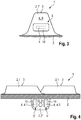
- Possible mounting locations for the sensor element 4 are in Figures 3 and 4 shown as an example. The attachment locations can also be used jointly, so that in addition to the sensor element 4 there are also further sensor elements.
- the Figures 3 and 4 each show an enlarged section of the elastomer band 1 of FIG Figure 2 as a partial cut.
- the Figure 3 shows the elastomer band 1 in the area of one of the upward-facing projections 2.1, one projection 2.1 'being shown in a side view and the base body 2 of the elastomer band 1 in a longitudinal section.
- the Figure 4 shows the elastomer tape 1 in the area of one of the downward facing Protrusions 2.2, the one protrusion 2.2 'being shown in a side view and the base body 2 of the elastomer band 1 in a cross section.
- a fastening point 5 for the sensor element 4 can be formed by a wall surface 8, in particular an outer wall surface, of the one projection 2.1 '.
- the wall surface 8 is a wall surface of the one projection 2.1 ′ that is present in the longitudinal direction of the elastomer band 1.
- a cover element 10 or patches can be provided for fastening the sensor element 4 to the wall surface 8.
- the cover element 10 is glued to the wall surface 8 by means of an adhesive, and the sensor element 4 is arranged between the cover element 10 and the wall surface 8. In this way, the sensor element 4 is held on the wall surface 8 by the cover element 10.
- the cover element 10 preferably consists of an elastomer material or has such an elastomer material.
- the elastomer material can be identical to the elastomer material of the elastomer band 1.
- the adhesive is preferably a vulcanizing liquid.
- a further fastening point 5 'for the sensor element 4 can be formed by a wall surface 9, in particular the outer wall surface, of the one projection 2.2'.
- the wall surface 9 is a wall surface of the one protrusion 2.2 ′ that is transverse to the longitudinal direction of the elastomer band 1.
- Cover element 10 described may be provided to attach the sensor element 4 to the wall surface 9.
- the sensor element 4 can, for example, be provided twice or more in the area of the fastening point 5 '.
- a first sensor element 4.1 and a second sensor element 4.2 are then arranged at a predetermined distance from one another.
- Figures 5 to 8 show examples of individual stages in the assembly of the sensor element 4 on the surface of an elastomer band 1 'in order to produce the elastomer band 1 described above.
- an intended fastening point 5 ′′ on the surface 6 of the elastomer band 1 ′ is preferred. cleaned.
- a material layer 11 which increases the transmission power of the sensor element 4 such as a material layer containing copper, in particular a copper foil or a copper braid, can be attached, for example glued, to the surface 6 of the elastomer tape 1 ( Figure 5 ).
- the material layer 11 preferably covers the area around the fastening point 5 ′′ for the sensor element 4.
- the area around the fastening point 5 is coated with an adhesive 12 ( Figure 6 ) and then positioned the sensor element 4 at the fastening point 5 ′′ ( Figure 7 ).
- the cover element 10 already described above is then applied to the area of the fastening point 5 ′′ and an adhesive connection is made with the adhesive ( Figure 8 ).
- the cover element 10 thus overlays the sensor element 4, for example in order to thereby hold the sensor element 4 in position on the elastomer tape 1 '.
- the elastomer tape 1 is now produced.
- reference to a specific aspect or a specific embodiment or a specific configuration means that a specific feature or a specific property, which is described in connection with the respective aspect or the specific embodiment or the respective configuration, contain at least there is, but need not necessarily be included in all aspects or embodiments or refinements of the invention. It is expressly pointed out that any combination of the various features and / or structures and / or properties described in relation to the invention are encompassed by the invention, unless this is expressly or clearly contradicted by the context.
Landscapes
- Engineering & Computer Science (AREA)
- Mechanical Engineering (AREA)
- Chemical & Material Sciences (AREA)
- Combustion & Propulsion (AREA)
- Transportation (AREA)
- Tires In General (AREA)
Applications Claiming Priority (1)
| Application Number | Priority Date | Filing Date | Title |
|---|---|---|---|
| DE102018114384.2A DE102018114384A1 (de) | 2018-06-15 | 2018-06-15 | Elastomerband zum Übertragen einer Antriebskraft bei landwirtschaftlichen Maschinen und Verfahren zu dessen Herstellung sowie System zur Überwachung des Zustandes eines Elastomerbandes |
Publications (2)
| Publication Number | Publication Date |
|---|---|
| EP3581473A1 true EP3581473A1 (fr) | 2019-12-18 |
| EP3581473B1 EP3581473B1 (fr) | 2022-06-08 |
Family
ID=66175165
Family Applications (1)
| Application Number | Title | Priority Date | Filing Date |
|---|---|---|---|
| EP19168613.8A Active EP3581473B1 (fr) | 2018-06-15 | 2019-04-11 | Bande d'élastomère permettant de transmettre une force d'entraînement dans des machines agricoles et son procédé de fabrication ainsi que système de surveillance de l'état d'une bande d'élastomère |
Country Status (2)
| Country | Link |
|---|---|
| EP (1) | EP3581473B1 (fr) |
| DE (1) | DE102018114384A1 (fr) |
Citations (8)
| Publication number | Priority date | Publication date | Assignee | Title |
|---|---|---|---|---|
| EP0798241A2 (fr) * | 1996-03-29 | 1997-10-01 | ContiTech Transportbandsysteme GmbH | Courroie du convoyeur pourvue de transpondeurs encastrés |
| EP0906839A2 (fr) * | 1997-09-17 | 1999-04-07 | BRIDGESTONE/FIRESTONE, Inc. | Procédé et appareil pour coller une étiquette active à un patch et un pneu |
| US20060016534A1 (en) * | 2003-01-23 | 2006-01-26 | Michelin Recherch Et Technique S.A. | Tire having an element or covering attached to a surface thereof |
| US20070175554A1 (en) * | 2005-12-13 | 2007-08-02 | Michelin Recherche Et Technique S.A. | Patch for fixing an electronic system to a tire |
| US20150191173A1 (en) * | 2010-12-14 | 2015-07-09 | Camoplast Solideal, Inc. | Track drive mode management system and methods |
| WO2017049393A1 (fr) * | 2015-09-21 | 2017-03-30 | Soucy International Inc. | Système de piste intelligente comportant des capteurs intégrés et son procédé d'utilisation |
| EP3185097A1 (fr) | 2015-12-22 | 2017-06-28 | Deere & Company | Système de commande de véhicule avec détection de température de piste |
| EP3199385A1 (fr) * | 2014-09-23 | 2017-08-02 | Mesnac Co. Ltd. | Appareil de détection d'ondes acoustiques de surface passif de type pastille et pneu intelligent |
-
2018
- 2018-06-15 DE DE102018114384.2A patent/DE102018114384A1/de not_active Withdrawn
-
2019
- 2019-04-11 EP EP19168613.8A patent/EP3581473B1/fr active Active
Patent Citations (8)
| Publication number | Priority date | Publication date | Assignee | Title |
|---|---|---|---|---|
| EP0798241A2 (fr) * | 1996-03-29 | 1997-10-01 | ContiTech Transportbandsysteme GmbH | Courroie du convoyeur pourvue de transpondeurs encastrés |
| EP0906839A2 (fr) * | 1997-09-17 | 1999-04-07 | BRIDGESTONE/FIRESTONE, Inc. | Procédé et appareil pour coller une étiquette active à un patch et un pneu |
| US20060016534A1 (en) * | 2003-01-23 | 2006-01-26 | Michelin Recherch Et Technique S.A. | Tire having an element or covering attached to a surface thereof |
| US20070175554A1 (en) * | 2005-12-13 | 2007-08-02 | Michelin Recherche Et Technique S.A. | Patch for fixing an electronic system to a tire |
| US20150191173A1 (en) * | 2010-12-14 | 2015-07-09 | Camoplast Solideal, Inc. | Track drive mode management system and methods |
| EP3199385A1 (fr) * | 2014-09-23 | 2017-08-02 | Mesnac Co. Ltd. | Appareil de détection d'ondes acoustiques de surface passif de type pastille et pneu intelligent |
| WO2017049393A1 (fr) * | 2015-09-21 | 2017-03-30 | Soucy International Inc. | Système de piste intelligente comportant des capteurs intégrés et son procédé d'utilisation |
| EP3185097A1 (fr) | 2015-12-22 | 2017-06-28 | Deere & Company | Système de commande de véhicule avec détection de température de piste |
Also Published As
| Publication number | Publication date |
|---|---|
| EP3581473B1 (fr) | 2022-06-08 |
| DE102018114384A1 (de) | 2019-12-19 |
Similar Documents
| Publication | Publication Date | Title |
|---|---|---|
| WO2004048132A1 (fr) | Dispositif de maintien pour fixer un element electronique | |
| DE112007001902T5 (de) | Radlagerbaugruppe mit Sensor | |
| DE2313586A1 (de) | Fahrzeugluftreifen, insbesondere fuer lastkraftwagen | |
| DE1680471A1 (de) | Verstaerkung aus Metallschnueren fuer Reifen | |
| DE112009002662T5 (de) | Radlager mit Sensor | |
| DE102010003789B4 (de) | Elastisches Lager mit in seiner Hauptebene beidseitig eingeschnittener Grundplatte | |
| DE102005027104B4 (de) | Fahrzeugreifen | |
| DE3125808A1 (de) | Kunststoff-formstreifen bzw. -pressprofilleiste | |
| EP3581473B1 (fr) | Bande d'élastomère permettant de transmettre une force d'entraînement dans des machines agricoles et son procédé de fabrication ainsi que système de surveillance de l'état d'une bande d'élastomère | |
| EP1633580B1 (fr) | Pneu avec transpondeur | |
| DE2156745C3 (de) | Spurkette für ein mit einem elastischen Abstandsglied versehenes Rad, insbesondere ein Rad für Erdbewegungsfahrzeuge | |
| DE60119692T2 (de) | Bandraupe und ihr Herstellungsverfahren | |
| DE102018205428A1 (de) | Spoiler mit elastischem Positionierelement, Kraftfahrzeug mit einem solchen Spoiler und Verfahren zum Anbringen eines solchen Spoilers an einem Fahrzeug | |
| DE102019208229A1 (de) | Fahrzeug mit Unterbodensensorik | |
| DE102005023597A1 (de) | Fahrzeugreifen | |
| EP1688276A2 (fr) | Bandage pneumatique | |
| DE112015002707B4 (de) | Luftreifen und Verfahren zum Herstellen desselben | |
| DE102007031446B3 (de) | Dichtelement für eine Lenksäule eines Kraftfahrzeuges | |
| DE4204973C2 (de) | Verfahren zum Herstellen einer Gelenkscheibe sowie eine Gelenkscheibe zum Verbinden von Wellenflanschen | |
| EP3002179B1 (fr) | Train de roulement pour un engin de travail | |
| DE102011111278A1 (de) | Vorrichtung und Verfahren zum Montieren einer Dichtung | |
| DE102017115066A1 (de) | Montagebaugruppe | |
| DE102016225396A1 (de) | Raupenkette, insbesondere Gummiraupenkette | |
| DE10236140A1 (de) | Vorrichtung zum Messen des Druckes und/oder der Lufttemperatur eines Reifens | |
| DE102017209539A1 (de) | Fahrzeugreifen |
Legal Events
| Date | Code | Title | Description |
|---|---|---|---|
| PUAI | Public reference made under article 153(3) epc to a published international application that has entered the european phase |
Free format text: ORIGINAL CODE: 0009012 |
|
| STAA | Information on the status of an ep patent application or granted ep patent |
Free format text: STATUS: THE APPLICATION HAS BEEN PUBLISHED |
|
| AK | Designated contracting states |
Kind code of ref document: A1 Designated state(s): AL AT BE BG CH CY CZ DE DK EE ES FI FR GB GR HR HU IE IS IT LI LT LU LV MC MK MT NL NO PL PT RO RS SE SI SK SM TR |
|
| AX | Request for extension of the european patent |
Extension state: BA ME |
|
| STAA | Information on the status of an ep patent application or granted ep patent |
Free format text: STATUS: REQUEST FOR EXAMINATION WAS MADE |
|
| 17P | Request for examination filed |
Effective date: 20200618 |
|
| RBV | Designated contracting states (corrected) |
Designated state(s): AL AT BE BG CH CY CZ DE DK EE ES FI FR GB GR HR HU IE IS IT LI LT LU LV MC MK MT NL NO PL PT RO RS SE SI SK SM TR |
|
| GRAP | Despatch of communication of intention to grant a patent |
Free format text: ORIGINAL CODE: EPIDOSNIGR1 |
|
| STAA | Information on the status of an ep patent application or granted ep patent |
Free format text: STATUS: GRANT OF PATENT IS INTENDED |
|
| INTG | Intention to grant announced |
Effective date: 20211123 |
|
| GRAS | Grant fee paid |
Free format text: ORIGINAL CODE: EPIDOSNIGR3 |
|
| GRAA | (expected) grant |
Free format text: ORIGINAL CODE: 0009210 |
|
| STAA | Information on the status of an ep patent application or granted ep patent |
Free format text: STATUS: THE PATENT HAS BEEN GRANTED |
|
| AK | Designated contracting states |
Kind code of ref document: B1 Designated state(s): AL AT BE BG CH CY CZ DE DK EE ES FI FR GB GR HR HU IE IS IT LI LT LU LV MC MK MT NL NO PL PT RO RS SE SI SK SM TR |
|
| REG | Reference to a national code |
Ref country code: AT Ref legal event code: REF Ref document number: 1496757 Country of ref document: AT Kind code of ref document: T Effective date: 20220615 Ref country code: CH Ref legal event code: EP |
|
| REG | Reference to a national code |
Ref country code: DE Ref legal event code: R096 Ref document number: 502019004549 Country of ref document: DE |
|
| REG | Reference to a national code |
Ref country code: IE Ref legal event code: FG4D Free format text: LANGUAGE OF EP DOCUMENT: GERMAN |
|
| REG | Reference to a national code |
Ref country code: LT Ref legal event code: MG9D |
|
| REG | Reference to a national code |
Ref country code: NL Ref legal event code: MP Effective date: 20220608 |
|
| PG25 | Lapsed in a contracting state [announced via postgrant information from national office to epo] |
Ref country code: SE Free format text: LAPSE BECAUSE OF FAILURE TO SUBMIT A TRANSLATION OF THE DESCRIPTION OR TO PAY THE FEE WITHIN THE PRESCRIBED TIME-LIMIT Effective date: 20220608 Ref country code: NO Free format text: LAPSE BECAUSE OF FAILURE TO SUBMIT A TRANSLATION OF THE DESCRIPTION OR TO PAY THE FEE WITHIN THE PRESCRIBED TIME-LIMIT Effective date: 20220908 Ref country code: LT Free format text: LAPSE BECAUSE OF FAILURE TO SUBMIT A TRANSLATION OF THE DESCRIPTION OR TO PAY THE FEE WITHIN THE PRESCRIBED TIME-LIMIT Effective date: 20220608 Ref country code: HR Free format text: LAPSE BECAUSE OF FAILURE TO SUBMIT A TRANSLATION OF THE DESCRIPTION OR TO PAY THE FEE WITHIN THE PRESCRIBED TIME-LIMIT Effective date: 20220608 Ref country code: GR Free format text: LAPSE BECAUSE OF FAILURE TO SUBMIT A TRANSLATION OF THE DESCRIPTION OR TO PAY THE FEE WITHIN THE PRESCRIBED TIME-LIMIT Effective date: 20220909 Ref country code: FI Free format text: LAPSE BECAUSE OF FAILURE TO SUBMIT A TRANSLATION OF THE DESCRIPTION OR TO PAY THE FEE WITHIN THE PRESCRIBED TIME-LIMIT Effective date: 20220608 Ref country code: ES Free format text: LAPSE BECAUSE OF FAILURE TO SUBMIT A TRANSLATION OF THE DESCRIPTION OR TO PAY THE FEE WITHIN THE PRESCRIBED TIME-LIMIT Effective date: 20220608 Ref country code: BG Free format text: LAPSE BECAUSE OF FAILURE TO SUBMIT A TRANSLATION OF THE DESCRIPTION OR TO PAY THE FEE WITHIN THE PRESCRIBED TIME-LIMIT Effective date: 20220908 |
|
| PG25 | Lapsed in a contracting state [announced via postgrant information from national office to epo] |
Ref country code: RS Free format text: LAPSE BECAUSE OF FAILURE TO SUBMIT A TRANSLATION OF THE DESCRIPTION OR TO PAY THE FEE WITHIN THE PRESCRIBED TIME-LIMIT Effective date: 20220608 Ref country code: LV Free format text: LAPSE BECAUSE OF FAILURE TO SUBMIT A TRANSLATION OF THE DESCRIPTION OR TO PAY THE FEE WITHIN THE PRESCRIBED TIME-LIMIT Effective date: 20220608 |
|
| PG25 | Lapsed in a contracting state [announced via postgrant information from national office to epo] |
Ref country code: NL Free format text: LAPSE BECAUSE OF FAILURE TO SUBMIT A TRANSLATION OF THE DESCRIPTION OR TO PAY THE FEE WITHIN THE PRESCRIBED TIME-LIMIT Effective date: 20220608 |
|
| PG25 | Lapsed in a contracting state [announced via postgrant information from national office to epo] |
Ref country code: SM Free format text: LAPSE BECAUSE OF FAILURE TO SUBMIT A TRANSLATION OF THE DESCRIPTION OR TO PAY THE FEE WITHIN THE PRESCRIBED TIME-LIMIT Effective date: 20220608 Ref country code: SK Free format text: LAPSE BECAUSE OF FAILURE TO SUBMIT A TRANSLATION OF THE DESCRIPTION OR TO PAY THE FEE WITHIN THE PRESCRIBED TIME-LIMIT Effective date: 20220608 Ref country code: RO Free format text: LAPSE BECAUSE OF FAILURE TO SUBMIT A TRANSLATION OF THE DESCRIPTION OR TO PAY THE FEE WITHIN THE PRESCRIBED TIME-LIMIT Effective date: 20220608 Ref country code: PT Free format text: LAPSE BECAUSE OF FAILURE TO SUBMIT A TRANSLATION OF THE DESCRIPTION OR TO PAY THE FEE WITHIN THE PRESCRIBED TIME-LIMIT Effective date: 20221010 Ref country code: EE Free format text: LAPSE BECAUSE OF FAILURE TO SUBMIT A TRANSLATION OF THE DESCRIPTION OR TO PAY THE FEE WITHIN THE PRESCRIBED TIME-LIMIT Effective date: 20220608 Ref country code: CZ Free format text: LAPSE BECAUSE OF FAILURE TO SUBMIT A TRANSLATION OF THE DESCRIPTION OR TO PAY THE FEE WITHIN THE PRESCRIBED TIME-LIMIT Effective date: 20220608 |
|
| PG25 | Lapsed in a contracting state [announced via postgrant information from national office to epo] |
Ref country code: PL Free format text: LAPSE BECAUSE OF FAILURE TO SUBMIT A TRANSLATION OF THE DESCRIPTION OR TO PAY THE FEE WITHIN THE PRESCRIBED TIME-LIMIT Effective date: 20220608 Ref country code: IS Free format text: LAPSE BECAUSE OF FAILURE TO SUBMIT A TRANSLATION OF THE DESCRIPTION OR TO PAY THE FEE WITHIN THE PRESCRIBED TIME-LIMIT Effective date: 20221008 |
|
| REG | Reference to a national code |
Ref country code: DE Ref legal event code: R097 Ref document number: 502019004549 Country of ref document: DE |
|
| PG25 | Lapsed in a contracting state [announced via postgrant information from national office to epo] |
Ref country code: AL Free format text: LAPSE BECAUSE OF FAILURE TO SUBMIT A TRANSLATION OF THE DESCRIPTION OR TO PAY THE FEE WITHIN THE PRESCRIBED TIME-LIMIT Effective date: 20220608 |
|
| PLBE | No opposition filed within time limit |
Free format text: ORIGINAL CODE: 0009261 |
|
| STAA | Information on the status of an ep patent application or granted ep patent |
Free format text: STATUS: NO OPPOSITION FILED WITHIN TIME LIMIT |
|
| PG25 | Lapsed in a contracting state [announced via postgrant information from national office to epo] |
Ref country code: DK Free format text: LAPSE BECAUSE OF FAILURE TO SUBMIT A TRANSLATION OF THE DESCRIPTION OR TO PAY THE FEE WITHIN THE PRESCRIBED TIME-LIMIT Effective date: 20220608 |
|
| 26N | No opposition filed |
Effective date: 20230310 |
|
| PG25 | Lapsed in a contracting state [announced via postgrant information from national office to epo] |
Ref country code: SI Free format text: LAPSE BECAUSE OF FAILURE TO SUBMIT A TRANSLATION OF THE DESCRIPTION OR TO PAY THE FEE WITHIN THE PRESCRIBED TIME-LIMIT Effective date: 20220608 |
|
| P01 | Opt-out of the competence of the unified patent court (upc) registered |
Effective date: 20230516 |
|
| PGFP | Annual fee paid to national office [announced via postgrant information from national office to epo] |
Ref country code: DE Payment date: 20230420 Year of fee payment: 5 |
|
| REG | Reference to a national code |
Ref country code: CH Ref legal event code: PL |
|
| GBPC | Gb: european patent ceased through non-payment of renewal fee |
Effective date: 20230411 |
|
| PG25 | Lapsed in a contracting state [announced via postgrant information from national office to epo] |
Ref country code: LU Free format text: LAPSE BECAUSE OF NON-PAYMENT OF DUE FEES Effective date: 20230411 |
|
| REG | Reference to a national code |
Ref country code: BE Ref legal event code: MM Effective date: 20230430 |
|
| PG25 | Lapsed in a contracting state [announced via postgrant information from national office to epo] |
Ref country code: MC Free format text: LAPSE BECAUSE OF FAILURE TO SUBMIT A TRANSLATION OF THE DESCRIPTION OR TO PAY THE FEE WITHIN THE PRESCRIBED TIME-LIMIT Effective date: 20220608 |
|
| PG25 | Lapsed in a contracting state [announced via postgrant information from national office to epo] |
Ref country code: GB Free format text: LAPSE BECAUSE OF NON-PAYMENT OF DUE FEES Effective date: 20230411 |
|
| PG25 | Lapsed in a contracting state [announced via postgrant information from national office to epo] |
Ref country code: MC Free format text: LAPSE BECAUSE OF FAILURE TO SUBMIT A TRANSLATION OF THE DESCRIPTION OR TO PAY THE FEE WITHIN THE PRESCRIBED TIME-LIMIT Effective date: 20220608 Ref country code: LI Free format text: LAPSE BECAUSE OF NON-PAYMENT OF DUE FEES Effective date: 20230430 Ref country code: IT Free format text: LAPSE BECAUSE OF FAILURE TO SUBMIT A TRANSLATION OF THE DESCRIPTION OR TO PAY THE FEE WITHIN THE PRESCRIBED TIME-LIMIT Effective date: 20220608 Ref country code: GB Free format text: LAPSE BECAUSE OF NON-PAYMENT OF DUE FEES Effective date: 20230411 Ref country code: FR Free format text: LAPSE BECAUSE OF NON-PAYMENT OF DUE FEES Effective date: 20230430 Ref country code: CH Free format text: LAPSE BECAUSE OF NON-PAYMENT OF DUE FEES Effective date: 20230430 |
|
| REG | Reference to a national code |
Ref country code: IE Ref legal event code: MM4A |
|
| PG25 | Lapsed in a contracting state [announced via postgrant information from national office to epo] |
Ref country code: BE Free format text: LAPSE BECAUSE OF NON-PAYMENT OF DUE FEES Effective date: 20230430 |
|
| PG25 | Lapsed in a contracting state [announced via postgrant information from national office to epo] |
Ref country code: IE Free format text: LAPSE BECAUSE OF NON-PAYMENT OF DUE FEES Effective date: 20230411 |
|
| PG25 | Lapsed in a contracting state [announced via postgrant information from national office to epo] |
Ref country code: IE Free format text: LAPSE BECAUSE OF NON-PAYMENT OF DUE FEES Effective date: 20230411 |