EP3581009A1 - Halterahmen für einen frontkraftheber - Google Patents
Halterahmen für einen frontkraftheber Download PDFInfo
- Publication number
- EP3581009A1 EP3581009A1 EP19179044.3A EP19179044A EP3581009A1 EP 3581009 A1 EP3581009 A1 EP 3581009A1 EP 19179044 A EP19179044 A EP 19179044A EP 3581009 A1 EP3581009 A1 EP 3581009A1
- Authority
- EP
- European Patent Office
- Prior art keywords
- pos
- counter
- holding frame
- contact surface
- coupling
- Prior art date
- Legal status (The legal status is an assumption and is not a legal conclusion. Google has not performed a legal analysis and makes no representation as to the accuracy of the status listed.)
- Granted
Links
Images
Classifications
-
- A—HUMAN NECESSITIES
- A01—AGRICULTURE; FORESTRY; ANIMAL HUSBANDRY; HUNTING; TRAPPING; FISHING
- A01B—SOIL WORKING IN AGRICULTURE OR FORESTRY; PARTS, DETAILS, OR ACCESSORIES OF AGRICULTURAL MACHINES OR IMPLEMENTS, IN GENERAL
- A01B59/00—Devices specially adapted for connection between animals or tractors and agricultural machines or implements
- A01B59/06—Devices specially adapted for connection between animals or tractors and agricultural machines or implements for machines mounted on tractors
- A01B59/064—Devices specially adapted for connection between animals or tractors and agricultural machines or implements for machines mounted on tractors for connection to the front of the tractor
-
- A—HUMAN NECESSITIES
- A01—AGRICULTURE; FORESTRY; ANIMAL HUSBANDRY; HUNTING; TRAPPING; FISHING
- A01B—SOIL WORKING IN AGRICULTURE OR FORESTRY; PARTS, DETAILS, OR ACCESSORIES OF AGRICULTURAL MACHINES OR IMPLEMENTS, IN GENERAL
- A01B59/00—Devices specially adapted for connection between animals or tractors and agricultural machines or implements
- A01B59/06—Devices specially adapted for connection between animals or tractors and agricultural machines or implements for machines mounted on tractors
- A01B59/066—Devices specially adapted for connection between animals or tractors and agricultural machines or implements for machines mounted on tractors of the type comprising at least two lower arms and one upper arm generally arranged in a triangle, e.g. three-point hitches
-
- A—HUMAN NECESSITIES
- A01—AGRICULTURE; FORESTRY; ANIMAL HUSBANDRY; HUNTING; TRAPPING; FISHING
- A01B—SOIL WORKING IN AGRICULTURE OR FORESTRY; PARTS, DETAILS, OR ACCESSORIES OF AGRICULTURAL MACHINES OR IMPLEMENTS, IN GENERAL
- A01B59/00—Devices specially adapted for connection between animals or tractors and agricultural machines or implements
- A01B59/06—Devices specially adapted for connection between animals or tractors and agricultural machines or implements for machines mounted on tractors
- A01B59/061—Devices specially adapted for connection between animals or tractors and agricultural machines or implements for machines mounted on tractors specially adapted for enabling connection or disconnection controlled from the driver's seat
- A01B59/062—Devices specially adapted for connection between animals or tractors and agricultural machines or implements for machines mounted on tractors specially adapted for enabling connection or disconnection controlled from the driver's seat the connection comprising a rigid interface frame on the tractor
-
- A—HUMAN NECESSITIES
- A01—AGRICULTURE; FORESTRY; ANIMAL HUSBANDRY; HUNTING; TRAPPING; FISHING
- A01B—SOIL WORKING IN AGRICULTURE OR FORESTRY; PARTS, DETAILS, OR ACCESSORIES OF AGRICULTURAL MACHINES OR IMPLEMENTS, IN GENERAL
- A01B63/00—Lifting or adjusting devices or arrangements for agricultural machines or implements
- A01B63/02—Lifting or adjusting devices or arrangements for agricultural machines or implements for implements mounted on tractors
- A01B63/10—Lifting or adjusting devices or arrangements for agricultural machines or implements for implements mounted on tractors operated by hydraulic or pneumatic means
- A01B63/102—Lifting or adjusting devices or arrangements for agricultural machines or implements for implements mounted on tractors operated by hydraulic or pneumatic means characterised by the location of the mounting on the tractor, e.g. on the rear part
- A01B63/108—Lifting or adjusting devices or arrangements for agricultural machines or implements for implements mounted on tractors operated by hydraulic or pneumatic means characterised by the location of the mounting on the tractor, e.g. on the rear part on the front part
Definitions
- the invention relates to a holding frame for holding a front linkage on a tractor.
- Such a holding frame has an articulated part on which the front linkage is articulated. This articulation helps that the front linkage can carry out the desired movement sequences relative to a support structure of the tractor.
- the present invention has for its object to improve a support frame in terms of its functionality for a front linkage.
- the holding frame has an articulation part for articulating the front power lift and a connecting part for connecting the articulation part to a support structure of the tractor.
- the articulation part contains a contact area
- the connecting part contains a counter-contact area.
- the contact area and the counter contact area interact with one another in order to achieve a mechanical coupling of the articulation part with the connecting part.
- the contact area and the counter-contact area are releasably clamped together by clamping means (e.g. clamping screws). It is therefore a releasable coupling between the articulation part and the connecting part.
- the coupling is designed in such a way that the coupled articulation part is optionally in one of several possible, different coupling positions with respect to the connecting part during the coupling.
- the different coupling positions enable the holding frame to be adapted to different boundary conditions (e.g. different size of tractor tires). Consequently, the front linkage or lower link mounted on the holding frame can maintain, for example, approximately the same desired relative position with respect to the ground or the front axle of the tractor despite different boundary conditions. This allows the same front linkage without any special technical changes and Adaptations to different tractors are used, which significantly supports its functionality with regard to different applications.
- the clamping devices can be different, e.g. be designed as clamping screws or clamping bolts.
- the number of individual clamping devices in a contact area can be defined differently depending on the forces to be transmitted between the articulation part and the connecting part.
- the articulation part preferably extends along a vertical direction (preferably a vertical axis of the tractor), while the connecting part extends along a longitudinal direction perpendicular to the vertical direction (preferably a longitudinal axis of the tractor).
- a vertical direction preferably a vertical axis of the tractor
- the connecting part extends along a longitudinal direction perpendicular to the vertical direction (preferably a longitudinal axis of the tractor).
- Different coupling positions can be implemented inexpensively and geometrically precisely by preferably providing at least one spacer between the contact area and the counter-contact area. Depending on the intended number and dimensioning or geometric configuration of the spacers, the articulation part can then be transferred to different coupling positions.
- the contact area has a contact surface or consists of a contact surface which cooperates with a counter contact surface of the counter contact area, the clamping direction of the clamping means being effective transversely (in particular approximately at right angles) to the contact surface and the counter contact surface.
- the counter abutment area has the counter abutment surface or consists of the counter abutment surface.
- the contact surface and the counter-contact surface are preferably arranged parallel to one another, which supports an assembly-friendly handling of the articulation part and the connecting part.
- the contact surface and the counter-contact surface are each planar, which keeps the manufacture of the contact area and the counter-contact area technically simple.
- the contact surface and / or the counter contact surface is preferably arranged at a coupling angle greater than 0 ° and less than 90 ° with respect to a reference straight line, in particular the aforementioned vertical direction of the holding frame.
- the coupling angle is 30 ° to 60 °, in particular 45 °, with respect to the reference straight line. This supports the realization of the desired different coupling positions with a space-saving construction of the holding frame. In addition, this geometry enables efficient power transmission between the support structure of the tractor and the front linkage.
- the connecting part of the holding frame is detachably coupled to the articulation part.
- the connecting part can be formed in one piece or in several parts. It can be releasably or non-releasably attached to the support structure of the tractor, as a result of which the entire holding frame is also attached to the support structure.
- the connecting part can be an integral part of the support structure from the outset.
- the connecting part can be subsequently connected to the supporting structure, e.g. by welding.
- the articulation part has a plurality of contact areas along the vertical direction. This has a favorable effect - in particular in the case of specific constructional designs of the holding frame - on stable force transmission between the connecting part and the articulation part.
- the connection part can be designed with a plurality of counter-abutment areas or have a plurality of connection components, each with a counter-abutment area.
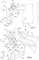
- Fig. 1 shows schematically a holding frame 10 with a link part 12 and a connecting part 14.
- the holding frame 10 is fastened to a schematically illustrated support structure 16 (eg chassis) of a tractor 18 and is used for the articulated mounting of a front linkage (not shown here) with two lower links and one upper link.
- Two lower links of the front linkage are articulated at a parallel distance to a hinge pin 20 of the articulation part 12 in order to be able to carry out pivoting movements of the front linkage approximately along a vertical direction 22.
- the hinge axis of the hinge pin 20 runs in Fig. 1 perpendicular to the drawing plane.
- the upper link of the front linkage is articulated on a joint section 21 of the articulation part 12 ( Fig. 2 ).
- the connecting part 14 is aligned at least in sections along a longitudinal direction 24.
- the vertical direction 22 and the longitudinal direction 24 are arranged at right angles to one another and each run perpendicular to a transverse direction 26, along which the hinge axis of the hinge pin 20 extends.
- the articulation part 12 has a contact area 28 which cooperates with a counter-contact area 30 of the connecting part 14 in order to achieve a mechanical coupling between the articulation part 12 and the connecting part 14.
- the contact area 28 has a contact surface 32 which cooperates with a counter contact surface 34 of the counter contact area 30 for coupling.
- the contact surface 32 and the counter contact surface 34 remain fixed to one another by clamping means 36 in the form of a plurality of clamping screws.
- a clamping force direction 38 of the clamping means 36 extends transversely to the contact surface 32 and the counter-contact surface 34.
- cross can mean different angles greater than 0 ° and less than 180 ° of the clamping force direction 38 with respect to the contact surface 32 and / or the counter-contact surface 34. at according to the embodiment Fig. 1 the clamping force direction 38 is oriented at an angle of 90 ° relative to the contact surface 32 and the counter contact surface 34.
- the design and number of the individual clamping means 36 can be different. While in the embodiment according to 1 and 2 two sets of three, that is a total of six, clamping screws are provided, depending on the required power transmission between the articulation part 12 and the connecting part 14, a different number may also be suitable.
- a coupling area 48 (ie a cooperating pair of a contact area 28 and a counter-contact area 30 with possibly at least one spacer 40) along the transverse direction 26 is supplemented by a second such coupling area 48.
- the two side cheeks 50 of the articulation part 12 of identical design are each coupled to one of the two connecting struts 52 of the connecting part 14, which are likewise of identical design.
- the second coupling area 48 is invisible.
- the cross section of the contact surface 32 and / or the counter contact surface 34 can be configured differently. If the surfaces do not have a flat plane, they are preferably designed as mutual negative reliefs in order to enable a form-fitting contact position with one another.
- the contact surface 32 and the counter contact surface 34 are each formed as a flat plane and lie parallel to one another during the coupling.
- the contact surface 32 and the counter-contact surface 34 with the vertical direction 22 as a reference straight line include a coupling angle w_K of approximately 45 °. Other preferred coupling angles w_K are in the range from 30 ° to 60 ° with respect to the vertical direction 22.
- At least one spacer 40 achieve different coupling positions of the articulation part 12 with respect to the vertical direction 22 and the longitudinal direction 24. Consequently, these coupling positions of the articulation part 12 are also arranged differently relative to the connecting part 14.
- two spacers 40 are used, so that a total of three different coupling positions Pos_1, Pos_2 and Pos_3 can be realized.
- the different coupling positions Pos_2 and Pos_3 are indicated by a shifted and dashed representation of a wall opening 42 of the articulation part 12.
- the mechanical coupling with a different number of spacers 40 can be advantageously used, for example, with different sizes of tractor tires on a front axle 44 of the tractor 18.
- the front axle 44 is arranged parallel to the transverse direction 26.
- the use of an appropriately dimensioned spacer 40 and / or a corresponding number of spacers 40 ensures that the front linkage always maintains an optimal distance from the ground and from the front axle 44.
- No spacer 40 is used for the smallest tire size (coupling position Pos_1).
- a spacer 40 is arranged between the contact surface 32 and the counter contact surface 34 (coupling position Pos_2).
- the contact surface 32 and the counter-contact surface 34 - as in FIG Fig. 2 shown - two spacers 40 arranged (coupling position Pos_3).
- the thickness of the spacer 40 in the clamping force direction 38 is e.g. 69 mm.
- the displacement of the articulation part 12 from its first coupling position Pos_1 to its third coupling position Pos_3 is 100 mm along the vertical direction 22 and 95 mm along the longitudinal direction 24, for example.
- the spacers 40 are penetrated by through holes 46 in order to brace or screw the clamping means 36 from the counter abutment area 30 to the articulation part 12.
- Fig. 3 shows a further embodiment of the holding frame 10.
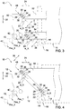
- the connecting part 14 contains an additional connecting strut 54 offset along the height direction 22, which has a counter abutment area 30 with a counter abutment surface 34.
- the latter belongs to an additional coupling area 56, which is arranged offset in the height direction 22 with respect to the coupling area 48.
- the articulation part 12 has two contact areas 28 offset along the height direction 22.
- the coupling angles w_K of both coupling areas 48, 56 are preferably identical.
- the connecting part 14 has a single connecting strut 52 along the height direction 22.
- the connecting strut 52 has two spaced apart along the height direction 22 Counter abutment areas 30 with two counter abutment surfaces 34, which are part of two coupling areas 48, 56.
- the side cheek 50 of the articulation part 12 contains two mutually spaced contact areas 28 with two contact surfaces 32 along the height direction 22.
- the coupling angles w_K of both coupling areas 48, 56 are in turn preferably dimensioned identically.
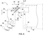
- Fig. 5 are the contact surface 32 and the counter-contact surface 34 in comparison to the variant according to Fig. 1 offset by approximately 90 ° with respect to the apex of the coupling angle w_K.
- the amount of in Fig. 5 indicated coupling angle w_K is therefore identical to the amount of in Fig. 1 shown coupling angle w_K.
- the geometric configuration of the coupling area 48 according to Fig. 5 enables the same different coupling positions Pos_1, Pos_2, Pos_3 without the use of spacers 40.
- each of the coupling positions Pos_1, Pos_2, Pos_3 it is sufficient for each of the coupling positions Pos_1, Pos_2, Pos_3 to hold a corresponding number of clamping devices 36, which then depend on the respectively desired coupling position Pos_1, Pos_2 or Pos_3 can be used.
- the respective coupling position Pos_1, Pos_2 or Pos_3 results from the selected parallel offset of the contact surface 32 with respect to the counter contact surface 34.
- Fig. 5 shown number of six clamping screws 36 only as an example.
- a different number of clamping devices 36 can also be suitable for realizing the three different coupling positions Pos_1, Pos_2 or Pos_3.
Landscapes
- Life Sciences & Earth Sciences (AREA)
- Engineering & Computer Science (AREA)
- Mechanical Engineering (AREA)
- Soil Sciences (AREA)
- Environmental Sciences (AREA)
- Zoology (AREA)
- Agricultural Machines (AREA)
- Body Structure For Vehicles (AREA)
Abstract
Description
- Die Erfindung betrifft einen Halterahmen zur Halterung eines Frontkrafthebers an einem Traktor.
- Ein derartiger Halterahmen weist einen Anlenkteil auf, an dem der Frontkraftheber gelenkig gelagert ist. Diese Anlenkung trägt dazu bei, dass der Frontkraftheber die gewünschten Bewegungsabläufe relativ zu einer Tragstruktur des Traktors durchführen kann.
- Der vorliegenden Erfindung liegt die Aufgabe zugrunde, einen Halterahmen hinsichtlich seiner Funktionalität für einen Frontkraftheber zu verbessern.
- Diese Aufgabe wird durch einen Halterahmen mit den Merkmalen des Patentanspruchs 1 gelöst.
- Weitere vorteilhafte Ausgestaltungen des erfindungsgemäßen Halterahmens gehen aus den Unteransprüchen hervor.
- Gemäß Anspruch 1 weist der Halterahmen einen Anlenkteil zur Anlenkung des Frontkrafthebers und einen Verbindungsteil zur Verbindung des Anlenkteils mit einer Tragstruktur des Traktors auf. Der Anlenkteil enthält einen Anlagebereich, während der Verbindungsteil einen Gegenanlagebereich enthält. Der Anlagebereich und der Gegenanlagebereich wirken miteinander zusammen, um eine mechanische Kopplung des Anlenkteils mit dem Verbindungsteil zu erzielen. Hierbei sind der Anlagebereich und der Gegenanlagebereich durch Spannmittel (z.B. Spannschrauben) miteinander lösbar verspannt. Es handelt sich also um eine lösbare Kopplung zwischen dem Anlenkteil und dem Verbindungsteil. Die Kopplung ist derart ausgebildet, dass sich der gekoppelte Anlenkteil während der Kopplung wahlweise in einer von mehreren möglichen, unterschiedlichen Kopplungspositionen bezüglich des Verbindungsteils befindet.
- Die unterschiedlichen Kopplungspositionen ermöglichen es, dass der Halterahmen an unterschiedliche Randbedingungen (z.B. unterschiedliche Größe der Traktorreifen) angepasst werden kann. Folglich kann der am Halterahmen montierte Frontkraftheber bzw. Unterlenker trotz unterschiedlicher Randbedingungen beispielsweise etwa dieselbe gewünschte Relativposition bezüglich des Erdbodens oder der Vorderachse des Traktors beibehalten. Hierdurch kann derselbe Frontkraftheber ohne besondere technische Veränderungen und Anpassungen an unterschiedlichen Traktoren verwendet werden, was seine Funktionalität hinsichtlich unterschiedlicher Anwendungen signifikant unterstützt.
- Die Spannmittel können unterschiedlich, z.B. als Spannschrauben oder Spannbolzen, ausgebildet sein. Die Anzahl einzelner Spannmittel an einem Anlagebereich kann abhängig von den zu übertragenden Kräften zwischen dem Anlenkteil und dem Verbindungsteil unterschiedlich festgelegt sein.
- Vorzugsweise erstreckt sich der Anlenkteil entlang einer Hochrichtung (vorzugsweise eine Hochachse des Traktors), während sich der Verbindungsteil entlang einer rechtwinklig zur Hochrichtung verlaufenden Längsrichtung (vorzugsweise eine Längsachse des Traktors) erstreckt. Mit Hilfe des Anlagebereichs und des Gegenanlagebereichs können deshalb konstruktionstechnisch einfach mehrere unterschiedliche Kopplungspositionen realisiert werden, indem der Anlenkteil beispielsweise entlang der Hochrichtung und/oder der Längsrichtung in unterschiedliche Positionen verlagerbar ist.
- Unterschiedliche Kopplungspositionen lassen sich kostengünstig und geometrisch präzise realisieren, indem vorzugsweise mindestens ein Abstandhalter zwischen dem Anlagebereich und dem Gegenanlagebereich vorgesehen ist. Abhängig von der vorgesehenen Anzahl und Dimensionierung bzw. geometrischen Ausgestaltung der Abstandhalter kann dann der Anlenkteil in unterschiedliche Kopplungspositionen überführt werden.
- In einer bevorzugten Ausführungsform weist der Anlagebereich eine Anlagefläche auf oder besteht aus einer Anlagefläche, welche mit einer Gegenanlagefläche des Gegenanlagebereichs zusammenwirkt, wobei die Spannrichtung der Spannmittel quer (insbesondere etwa rechtwinklig) zu der Anlagefläche und der Gegenanlagefläche wirksam ist. Eine derartige Konstruktion unterstützt mechanisch stabile Kopplungspositionen des Anlenkteils. Hierbei weist der Gegenanlagebereich die Gegenanlagefläche auf oder besteht aus der Gegenanlagefläche.
- Vorzugsweise sind die Anlagefläche und die Gegenanlagefläche parallel zueinander angeordnet, wodurch eine montagefreundliche Handhabung des Anlenkteils und des Verbindungsteils unterstützt wird. Insbesondere sind die Anlagefläche und die Gegenanlagefläche jeweils plan ausgebildet, was die Herstellung des Anlagebereichs und des Gegenanlagebereichs technisch einfach hält.
- Um bei der Realisierung der unterschiedlichen Kopplungspositionen den Fertigungsaufwand für den Halterahmen gering zu halten, ist die Anlagefläche und/oder die Gegenanlagefläche vorzugsweise in einem Kopplungswinkel größer 0° und kleiner 90° bezüglich einer Bezugsgeraden, insbesondere der vorgenannten Hochrichtung des Halterahmens, angeordnet.
- In weiter bevorzugten Ausführungsformen beträgt der Kopplungswinkel 30° bis 60°, insbesondere 45°, bezüglich der Bezugsgeraden. Dies unterstützt die Realisierung der gewünschten unterschiedlichen Kopplungspositionen bei einem raumsparenden Aufbau des Halterahmens. Außerdem ermöglicht diese Geometrie eine effiziente Kraftübertragung zwischen der Tragstruktur des Traktors und dem Frontkraftheber.
- Wie bereits erwähnt, ist der Verbindungsteil des Halterahmens mit dem Anlenkteil lösbar gekoppelt. Der Verbindungsteil kann einstückig oder mehrteilig ausgebildet sein. Er kann an der Tragstruktur des Traktors lösbar oder unlösbar befestigt sein, wodurch auch der gesamte Halterahmen an der Tragstruktur befestigt ist. Im Falle einer unlösbaren Befestigung an der Tragstruktur kann der Verbindungsteil von vornherein einstückiger Bestandteil der Tragstruktur sein. Alternativ kann der Verbindungsteil nachträglich mit der Tragstruktur verbunden sein, z.B. durch Verschweißen.
- In einer weiteren bevorzugten Ausführungsform weist der Anlenkteil entlang der Hochrichtung mehrere Anlagebereiche auf. Dies wirkt sich - insbesondere bei spezifischen konstruktionstechnischen Ausgestaltungen des Halterahmens - günstig auf eine stabile Kraftübertragung zwischen dem Verbindungsteil und dem Anlenkteil aus. Entsprechend kann der Verbindungsteil mit mehreren Gegenanlagebereichen ausgebildet sein oder mehrere Verbindungs-Bestandteile mit jeweils einem Gegenanlagebereich aufweisen.
- Der erfindungsgemäße Halterahmen wird im Folgenden anhand der beigefügten Zeichnungen näher erläutert. Dabei sind hinsichtlich ihrer Funktion übereinstimmende bzw. vergleichbare Bauteile mit denselben Bezugszeichen gekennzeichnet. Es zeigen:
- Fig. 1
- eine schematische Seitenansicht eines mit einem Traktor verbundenen Halterahmens,
- Fig. 2
- eine perspektivische Ansicht einer Ausführungsform des Halterahmens gemäß
Fig. 1 mit einer gegenüberFig. 1 geänderten Kopplungsposition seines Anlenkteils, - Fig. 3
- eine schematische Seitenansicht einer weiteren Ausführungsform des Halterahmens,
- Fig. 4
- eine schematische Seitenansicht einer weiteren Ausführungsform des Halterahmens, und
- Fig. 5
- eine schematische Seitenansicht einer weiteren Ausführungsform des Halterahmens.
-
Fig. 1 zeigt schematisch einen Halterahmen 10 mit einem Anlenkteil 12 und einem Verbindungsteil 14. Der Halterahmen 10 ist an einer schematisch dargestellten Tragstruktur 16 (z.B. Chassis) eines Traktors 18 befestigt und dient der gelenkigen Halterung eines hier nicht dargestellten Frontkrafthebers mit zwei Unterlenkern und einem Oberlenker. Dabei sind zwei Unterlenker des Frontkrafthebers mit Parallelabstand an einem Gelenkbolzen 20 des Anlenkteils 12 angelenkt, um Schwenkbewegungen des Frontkrafthebers etwa entlang einer Hochrichtung 22 durchführen zu können. Die Gelenkachse des Gelenkbolzens 20 verläuft inFig. 1 lotrecht zur Zeichenblattebene. - Der bereits erwähnte und hier nicht dargestellte Oberlenker des Frontkrafthebers ist an einem Gelenkabschnitt 21 des Anlenkteils 12 angelenkt (
Fig. 2 ). - Während sich der Anlenkteil 12 entlang der Hochrichtung 22 erstreckt, ist der Verbindungsteil 14 zumindest abschnittsweise entlang einer Längsrichtung 24 ausgerichtet. Die Hochrichtung 22 und die Längsrichtung 24 sind rechtwinklig zueinander angeordnet und verlaufen jeweils lotrecht zu einer Querrichtung 26, entlang der sich die Gelenkachse des Gelenkbolzens 20 erstreckt.
- Gemäß
Fig. 1 weist der Anlenkteil 12 einen Anlagebereich 28 auf, welcher mit einem Gegenanlagebereich 30 des Verbindungsteils 14 zusammenwirkt, um eine mechanische Kopplung zwischen dem Anlenkteil 12 und dem Verbindungsteil 14 zu erreichen. Der Anlagebereich 28 weist eine Anlagefläche 32 auf, welche zur Kopplung mit einer Gegenanlagefläche 34 des Gegenanlagebereichs 30 zusammenwirkt. Während der Kopplung bleiben die Anlagefläche 32 und die Gegenanlagefläche 34 durch Spannmittel 36 in Form mehrerer Spannschrauben aneinander fixiert. Hierbei verläuft eine Spannkraftrichtung 38 der Spannmittel 36 quer zu der Anlagefläche 32 und der Gegenanlagefläche 34. Mit dem Begriff "quer" können unterschiedliche Winkel größer 0° und kleiner 180° der Spannkraftrichtung 38 bezüglich der Anlagefläche 32 und/oder der Gegenanlagefläche 34 gemeint sein. Bei der Ausführungsform gemäßFig. 1 ist die Spannkraftrichtung 38 in einem Winkel von 90° relativ zu der Anlagefläche 32 und der Gegenanlagefläche 34 ausgerichtet. - Die Ausgestaltung und Anzahl der einzelnen Spannmittel 36 kann unterschiedlich sein. Während bei der Ausführungsform gemäß
Fig. 1 und Fig. 2 zwei Sätze à drei, also insgesamt sechs, Spannschrauben vorgesehen sind, kann je nach erforderlicher Kraftübertragung zwischen dem Anlenkteil 12 und dem Verbindungsteil 14 auch eine andere Anzahl geeignet sein. - In
Fig. 2 ist zudem erkennbar, dass ein Kopplungsbereich 48 (d.h. ein zusammenwirkendes Paar aus einem Anlagebereich 28 und einem Gegenanlagebereich 30 mit ggf. mindestens einem Abstandhalter 40) entlang der Querrichtung 26 durch einen zweiten solchen Kopplungsbereich 48 ergänzt wird. Hierdurch sind die beiden gleichartig ausgebildeten Seitenwangen 50 des Anlenkteils 12 jeweils mit einem der beiden ebenfalls gleichartig ausgebildeten Verbindungsstreben 52 des Verbindungsteils 14 gekoppelt.Fig. 1 hingegen ist der zweite Kopplungsbereich 48 unsichtbar. - Der Querschnitt der Anlagefläche 32 und/oder der Gegenanlagefläche 34 können unterschiedlich ausgestaltet sein. Sofern die Flächen keine plane Ebene aufweisen, sind sie vorzugsweise als gegenseitige Negativreliefs ausgebildet, um eine formschlüssige Kontaktlage aneinander zu ermöglichen. In
Fig. 1 sind die Anlagefläche 32 und die Gegenanlagefläche 34 jeweils als eine plane Ebene ausgebildet und liegen während der Kopplung parallel aneinander an. Dabei schließen die Anlagefläche 32 und die Gegenanlagefläche 34 mit der Hochrichtung 22 als Bezugsgerade einen Kopplungswinkel w_K von etwa 45° ein. Andere bevorzugte Kopplungswinkel w_K liegen in dem Bereich von 30° bis 60° bezüglich der Hochrichtung 22. - Auf der Basis der beschriebenen mechanischen Kopplung lassen sich unter Verwendung mindestens eines Abstandhalters 40 (
Fig. 2 ) unterschiedliche Kopplungspositionen des Anlenkteils 12 bezüglich der Hochrichtung 22 und der Längsrichtung 24 erzielen. Folglich sind diese Kopplungspositionen des Anlenkteils 12 auch relativ zum Verbindungsteil 14 unterschiedlich angeordnet. Bei der hier inFig. 2 dargestellten Ausführungsform sind zwei Abstandhalter 40 verwendet, so dass insgesamt drei unterschiedliche Kopplungspositionen Pos_1, Pos_2 und Pos_3 realisierbar sind. InFig.1 sind die unterschiedlichen Kopplungspositionen Pos_2 und Pos_3 durch eine verlagerte und gestrichelte Darstellung einer Wandöffnung 42 des Anlenkteils 12 angedeutet. - Die mechanische Kopplung mit einer unterschiedlichen Anzahl von Abstandhaltern 40 lässt sich beispielsweise bei unterschiedlichen Größen der Traktorreifen an einer Vorderachse 44 des Traktors 18 vorteilhaft anwenden. Die Vorderachse 44 ist parallel zur Querrichtung 26 angeordnet. Im Falle eines Austausches einer spezifischen Reifengröße gegen eine andere Reifengröße lässt sich bei Verwendung eines entsprechend dimensionierten Abstandhalters 40 und/oder einer entsprechenden Anzahl von Abstandhaltern 40 erreichen, dass der Frontkraftheber immer einen optimalen Abstand zum Erdboden und zu der Vorderachse 44 behält.
- Bei der dargestellten Ausführungsform sind drei unterschiedliche Reifengrößen vorgesehen. Bei der kleinsten Reifengröße wird kein Abstandhalter 40 eingesetzt (Kopplungsposition Pos_1). Bei der mittleren Reifengröße wird zwischen der Anlagefläche 32 und der Gegenanlagefläche 34 ein Abstandhalter 40 angeordnet (Kopplungsposition Pos_2). Im Falle der größten Reifengröße werden zwischen der Anlagefläche 32 und der Gegenanlagefläche 34 - wie in
Fig. 2 dargestellt - zwei Abstandhalter 40 angeordnet (Kopplungsposition Pos_3). - Die Dicke des Abstandhalters 40 in Spannkraftrichtung 38 beträgt z.B. 69 mm. Die Verlagerung des Anlenkteils 12 aus seiner ersten Kopplungsposition Pos_1 in seine dritte Kopplungsposition Pos_3 beträgt entlang der Hochrichtung 22 beispielsweise 100 mm und entlang der Längsrichtung 24 beispielsweise 95 mm. Die Abstandhalter 40 sind von Durchgangslöchern 46 durchsetzt, um die Spannmittel 36 von dem Gegenanlagebereich 30 aus mit dem Anlenkteil 12 zu verspannen bzw. zu verschrauben.
-
Fig. 3 zeigt eine weitere Ausführungsform des Halterahmens 10. Der Verbindungsteil 14 enthält entlang der Höhenrichtung 22 versetzt eine zusätzliche Verbindungsstrebe 54, welche einen Gegenanlagebereich 30 mit einer Gegenanlagefläche 34 aufweist. Letztere gehört zu einem bezüglich des Kopplungsbereichs 48 in Höhenrichtung 22 versetzt angeordneten zusätzlichen Kopplungsbereich 56. Entsprechend weist der Anlenkteil 12 entlang der Höhenrichtung 22 versetzt zwei Anlagebereiche 28 auf. Die Kopplungswinkel w_K beider Kopplungsbereiche 48, 56 sind vorzugsweise identisch. - In
Fig. 4 weist der Verbindungsteil 14 entlang der Höhenrichtung 22 eine einzige Verbindungsstrebe 52 auf. Im Gegensatz zur Ausführungsform gemäßFig. 1 weist die Verbindungsstrebe 52 jedoch zwei entlang der Höhenrichtung 22 voneinander beabstandete Gegenanlagebereiche 30 mit zwei Gegenanlageflächen 34 auf, welche Bestandteil zweier Kopplungsbereiche 48, 56 sind. Entsprechend enthält die Seitenwange 50 des Anlenkteils 12 entlang der Höhenrichtung 22 zwei voneinander beabstandete Anlagebereiche 28 mit zwei Anlageflächen 32 auf. Die Kopplungswinkel w_K beider Kopplungsbereiche 48, 56 sind wiederum vorzugsweise identisch dimensioniert. - Bei der Ausführungsform gemäß
Fig. 5 sind die Anlagefläche 32 und die Gegenanlagefläche 34 im Vergleich zur Variante gemäßFig. 1 um etwa 90° versetzt bezüglich des Scheitelpunktes des Kopplungswinkels w_K angeordnet. Der Betrag des inFig. 5 angedeuteten Kopplungswinkels w_K ist deshalb identisch mit dem Betrag des inFig. 1 dargestellten Kopplungswinkels w_K. Die geometrische Ausgestaltung des Kopplungsbereichs 48 gemäßFig. 5 ermöglicht die gleichen unterschiedlichen Kopplungspositionen Pos_1, Pos_2, Pos_3 ohne Verwendung von Abstandhaltern 40. Vielmehr ist es ausreichend, für jede der Kopplungspositionen Pos_1, Pos_2, Pos_3 eine entsprechende Vielzahl von Spannmitteln 36 vorzuhalten, welche dann abhängig von der jeweils gewünschten Kopplungsposition Pos_1, Pos_2 oder Pos_3 eingesetzt werden. Die jeweilige Kupplungsposition Pos_1, Pos_2 oder Pos_3 ergibt sich dabei aus dem jeweils gewählten Parallelversatz der Anlagefläche 32 gegenüber der Gegenanlagefläche 34. - Hierbei ist die in
Fig. 5 dargestellte Anzahl von sechs Spannschrauben 36 lediglich beispielhaft. Zur Realisierung der drei unterschiedlichen Kopplungspositionen Pos_1, Pos_2 oder Pos_3 kann auch eine andere Anzahl von Spannmitteln 36 geeignet sein. - Es sei noch erwähnt, dass einzelne in den Zeichnungen dargestellte Details einerseits schematisch und andererseits nicht notwendigerweise maßstäblich sind.
Claims (10)
- Halterahmen (10) zur Halterung eines Frontkrafthebers an einem Traktor (18), wobei- der Halterahmen (10) einen Anlenkteil (12) zur Anlenkung des Frontkrafthebers und einen Verbindungsteil (14) zur Verbindung des Anlenkteils (12) mit einer Tragstruktur (16) des Traktors (18) aufweist,- der Anlenkteil (12) einen Anlagebereich (28) aufweist, welcher mit einem Gegenanlagebereich (30) des Verbindungsteils (14) zur Kopplung des Anlenkteils (12) mit dem Verbindungsteil (14) zusammenwirkt,- der Anlagebereich (28) und der Gegenanlagebereich (30) in einer Kopplungsposition (Pos_1, Pos_2, Pos_3) durch Spannmittel (36) miteinander lösbar verspannt sind, und- sich der gekoppelte Anlenkteil (12) wahlweise in einer von mehreren unterschiedlichen Kopplungspositionen (Pos_1, Pos_2, Pos_3) relativ zum Verbindungsteil (14) befindet.
- Halterahmen nach Anspruch 1, dadurch gekennzeichnet, dass sich der Anlenkteil (12) entlang einer Hochrichtung (22) erstreckt und sich der Verbindungsteil (14) entlang einer rechtwinklig zur Hochrichtung (22) verlaufenden Längsrichtung (24) erstreckt.
- Halterahmen nach Anspruch 2, dadurch gekennzeichnet, dass die Kopplungspositionen (Pos_1, Pos_2, Pos_3) des Anlenkteils (12) entlang der Hochrichtung (22) und/oder entlang der Längsrichtung (24) unterschiedlich sind.
- Halterahmen nach wenigstens einem der vorhergehenden Ansprüche, dadurch gekennzeichnet, dass zwischen dem Anlagebereich (28) und dem Gegenanlagebereich (30) mindestens ein Abstandhalter (40) lösbar angeordnet ist.
- Halterahmen nach wenigstens einem der vorhergehenden Ansprüche, dadurch gekennzeichnet, dass der Anlagebereich (28) eine Anlagefläche (32) aufweist, welche mit einer Gegenanlagefläche (34) des Gegenanlagebereichs (30) zusammenwirkt bei einer quer zu der Anlagefläche (32) und der Gegenanlagefläche (34) verlaufenden Spannkraftrichtung (38) der Spannmittel (36).
- Halterahmen nach Anspruch 5, dadurch gekennzeichnet, dass die Anlagefläche (32) und die Gegenanlagefläche (34) parallel zueinander angeordnet sind.
- Halterahmen nach Anspruch 5 oder 6, dadurch gekennzeichnet, dass die Anlagefläche (32) und/oder die Gegenanlagefläche (34) in einem Kopplungswinkel (w_K) größer 0° und kleiner 90° bezüglich einer Bezugsgeraden (22) angeordnet ist.
- Halterahmen nach Anspruch 7, dadurch gekennzeichnet, dass der Kopplungswinkel (w_K) 30° bis 60°, insbesondere 45°, bezüglich der Bezugsgeraden (22) beträgt.
- Halterahmen nach wenigstens einem der Ansprüche 2 bis 8, dadurch gekennzeichnet, dass der Anlenkteil (12) entlang der Hochrichtung (22) mehrere Anlagebereiche (28) aufweist.
- Traktor (18) mit einem Halterahmen (10) nach wenigstens einem der vorhergehenden Ansprüche.
Applications Claiming Priority (1)
| Application Number | Priority Date | Filing Date | Title |
|---|---|---|---|
| DE102018209347.4A DE102018209347A1 (de) | 2018-06-12 | 2018-06-12 | Halterahmen für einen Frontkraftheber |
Publications (2)
| Publication Number | Publication Date |
|---|---|
| EP3581009A1 true EP3581009A1 (de) | 2019-12-18 |
| EP3581009B1 EP3581009B1 (de) | 2022-06-22 |
Family
ID=66912536
Family Applications (1)
| Application Number | Title | Priority Date | Filing Date |
|---|---|---|---|
| EP19179044.3A Active EP3581009B1 (de) | 2018-06-12 | 2019-06-07 | Halterahmen für einen frontkraftheber |
Country Status (3)
| Country | Link |
|---|---|
| US (1) | US11399452B2 (de) |
| EP (1) | EP3581009B1 (de) |
| DE (1) | DE102018209347A1 (de) |
Citations (6)
| Publication number | Priority date | Publication date | Assignee | Title |
|---|---|---|---|---|
| GB2182834A (en) * | 1985-11-19 | 1987-05-28 | Alo Maskiner Ab | Tractor-implement coupling |
| DE3823491C1 (en) * | 1988-07-11 | 1989-05-18 | J I Case Gmbh, 4040 Neuss, De | Device for connecting an appliance to the front of motor vehicles of agricultural use, especially farm tractors |
| US20060018746A1 (en) * | 2004-06-25 | 2006-01-26 | John Gustafson | Faceplate |
| KR101354769B1 (ko) * | 2012-11-08 | 2014-01-22 | 재욱강업(주) | 트랙터용 작업기 연결구 |
| GB2512660A (en) * | 2013-04-05 | 2014-10-08 | Dromone Engineering Ltd | A quick hitch apparatus |
| US20170290258A1 (en) * | 2016-04-07 | 2017-10-12 | Peter J. Mollick | System for connecting implement to mobile machinery |
Family Cites Families (32)
| Publication number | Priority date | Publication date | Assignee | Title |
|---|---|---|---|---|
| BE636882A (de) * | 1962-09-04 | |||
| US3231294A (en) * | 1963-01-04 | 1966-01-25 | Deere & Co | Convertible coupler |
| US3592273A (en) * | 1968-01-18 | 1971-07-13 | William E Martin | Bodily attachable bulldozing assembly for tractors |
| JPS618138Y2 (de) * | 1980-08-26 | 1986-03-13 | ||
| US4832358A (en) * | 1988-04-01 | 1989-05-23 | Bull Garland E | Trailer fifth wheel-gooseneck conversion adapter |
| US5267747A (en) * | 1992-07-09 | 1993-12-07 | Thorn Howard R | Adaptor for a three point hitch |
| US5423394A (en) * | 1993-06-21 | 1995-06-13 | Kendle; Thomas D. | Three point hitch for hummer truck and other vehicles |
| US5538088A (en) * | 1994-11-17 | 1996-07-23 | Wait; Ernest H. | Combine header adaptor for a three-point hitch |
| US5697454A (en) * | 1995-07-18 | 1997-12-16 | Wilcox Brothers Incorporated | Three-point hitch assembly |
| US5709274A (en) * | 1996-02-22 | 1998-01-20 | Herbold; Greg H. | Conversion hitch |
| US6099012A (en) * | 1998-08-06 | 2000-08-08 | Mortimer; William W. | Cycle trailer hitch adapter |
| DE19951840B4 (de) * | 1999-10-28 | 2009-01-08 | Deere & Company, Moline | Anbauschnittstelle zur Kopplung von Arbeitsgeräten an ein Arbeitsfahrzeug |
| US6244813B1 (en) * | 2000-10-03 | 2001-06-12 | Roger W. Cataldo | Motorcycle towing device |
| US6431288B1 (en) * | 2000-11-21 | 2002-08-13 | Ronald J. Hoffart | Front three-point hitch system |
| US6474673B1 (en) * | 2001-03-20 | 2002-11-05 | Douglas Biggins | Trailer hitch conversion apparatus |
| US8875419B2 (en) * | 2001-11-12 | 2014-11-04 | Agri-Cover, Inc. | Snow plow |
| US6742600B2 (en) * | 2002-10-01 | 2004-06-01 | Hoelscher, Inc. | Implement coupler |
| US20050229445A1 (en) * | 2004-04-16 | 2005-10-20 | Poquette Joseph E | Excavator and backhoe attachment adapter |
| US7487843B2 (en) * | 2004-10-19 | 2009-02-10 | Cnh America Llc | Adjustable quick hitch |
| US7549666B1 (en) * | 2005-07-28 | 2009-06-23 | Donald Peter Sahlem | Articulating hitch for fifth wheel trailers |
| US20070098538A1 (en) * | 2005-11-01 | 2007-05-03 | Zettel Daniel M | Mount apparatus and method for attaching three-point hitch implements to front arms of a front-end loader |
| US7874391B2 (en) * | 2006-08-08 | 2011-01-25 | Clark Equipment Company | Multiple configuration utility vehicle |
| US8496070B2 (en) * | 2010-09-20 | 2013-07-30 | Deere & Company | Folding hitch lift arm |
| US8353359B2 (en) * | 2010-10-08 | 2013-01-15 | Amerequip Corporation | Apparatus and method for attaching a utility vehicle 3-point hitch to an implement bracket |
| US8555995B2 (en) * | 2010-12-03 | 2013-10-15 | Jerry Harris | Three-point front hitch mountable to the frame of an agricultural tractor |
| US8763715B2 (en) * | 2011-05-11 | 2014-07-01 | Ralph L. Osgood, Inc. | Quick-connect plow hitch |
| CA2830679A1 (en) * | 2012-11-05 | 2014-05-05 | Bruce E. Seeley | Universal snow plow mounting apparatus |
| US9434289B2 (en) * | 2013-05-31 | 2016-09-06 | Blane Alan Krause | Under vehicle cargo rack and securing mechanism |
| US9765492B2 (en) * | 2014-04-28 | 2017-09-19 | Robert L. Beaird, Iii | Snowplow apparatus for a motor vehicle |
| CA3007328C (en) * | 2015-12-07 | 2025-05-06 | Multihog R&D Limited | CONSTRUCTION EQUIPMENT |
| DE102018106856A1 (de) * | 2018-03-22 | 2019-09-26 | Wabco Gmbh | Messeinrichtung zum Messen von Kräften und/oder Momenten zwischen einem motorisierten Fahrzeug und einem davon gezogenen oder geschobenen Anhänger oder Anbaugerät |
| US11606894B2 (en) * | 2019-05-28 | 2023-03-21 | Copperhead Planter Products, Llc | Implement guidance module |
-
2018
- 2018-06-12 DE DE102018209347.4A patent/DE102018209347A1/de not_active Withdrawn
-
2019
- 2019-06-06 US US16/433,618 patent/US11399452B2/en active Active
- 2019-06-07 EP EP19179044.3A patent/EP3581009B1/de active Active
Patent Citations (6)
| Publication number | Priority date | Publication date | Assignee | Title |
|---|---|---|---|---|
| GB2182834A (en) * | 1985-11-19 | 1987-05-28 | Alo Maskiner Ab | Tractor-implement coupling |
| DE3823491C1 (en) * | 1988-07-11 | 1989-05-18 | J I Case Gmbh, 4040 Neuss, De | Device for connecting an appliance to the front of motor vehicles of agricultural use, especially farm tractors |
| US20060018746A1 (en) * | 2004-06-25 | 2006-01-26 | John Gustafson | Faceplate |
| KR101354769B1 (ko) * | 2012-11-08 | 2014-01-22 | 재욱강업(주) | 트랙터용 작업기 연결구 |
| GB2512660A (en) * | 2013-04-05 | 2014-10-08 | Dromone Engineering Ltd | A quick hitch apparatus |
| US20170290258A1 (en) * | 2016-04-07 | 2017-10-12 | Peter J. Mollick | System for connecting implement to mobile machinery |
Also Published As
| Publication number | Publication date |
|---|---|
| US20190373795A1 (en) | 2019-12-12 |
| DE102018209347A1 (de) | 2019-12-12 |
| EP3581009B1 (de) | 2022-06-22 |
| US11399452B2 (en) | 2022-08-02 |
Similar Documents
| Publication | Publication Date | Title |
|---|---|---|
| DE3500529C2 (de) | ||
| DE3205979C2 (de) | Lenkachse mit Hilfskraftunterstützung | |
| EP3572275B1 (de) | Fahrzeugsitz | |
| DE102016216803A1 (de) | Stabilisator-stützstruktur | |
| EP3569443B1 (de) | Fahrzeugsitz mit einer federeinrichtung | |
| EP1749939B1 (de) | Adapter für ein Arbeitsgerät als Teil einer Schnellwechselvorrichtung und Schnellwechselvorrichtung | |
| DE3628605C2 (de) | ||
| EP3456888B1 (de) | Baggerausleger und bagger | |
| EP3183467A1 (de) | Aggregatlager-anordnung | |
| EP2782864B1 (de) | Gegengewichtsfixierung | |
| DE102021001083B4 (de) | Hydraulisch gelenktes Transportfahrzeug, vorzugsweise mit variabler Breite und Spurweite | |
| EP3549417A1 (de) | Lenkeranordnung für einen dreipunkt-kraftheber eines traktors oder einer sonstigen landwirtschaftlichen arbeitsmaschine sowie dreipunkt-kraftheber | |
| EP3581009B1 (de) | Halterahmen für einen frontkraftheber | |
| DE2613718C2 (de) | An einem Schlepper anbringbare Dreipunkt-Anbauvorrichtung | |
| EP4052994B1 (de) | Hydraulisch gelenktes transportfahrzeug, vorzugsweise mit variabler breite und spurweite | |
| EP3425122B1 (de) | Mehrteiliger adapter für ein vorsatzgerät | |
| DE1557759B1 (de) | Ruettelegge | |
| DE202017001282U1 (de) | Neigungseinstellungsbaueinheit für ein an eine Maschine montiertes Werkzeug | |
| DE10124709B4 (de) | Front für Kraftfahrzeuge | |
| DE2950554C2 (de) | Steinsicherung für Drehpflüge | |
| WO2017036875A1 (de) | Lagerbock | |
| DE102005056973B4 (de) | Etage mit Einhängeösen | |
| AT517147B1 (de) | Ausleger für ein Nutzfahrzeug | |
| DE69203173T2 (de) | Greifer. | |
| DE69925127T2 (de) | Geräteanschlussvorrichtung und -verfahren |
Legal Events
| Date | Code | Title | Description |
|---|---|---|---|
| PUAI | Public reference made under article 153(3) epc to a published international application that has entered the european phase |
Free format text: ORIGINAL CODE: 0009012 |
|
| STAA | Information on the status of an ep patent application or granted ep patent |
Free format text: STATUS: THE APPLICATION HAS BEEN PUBLISHED |
|
| AK | Designated contracting states |
Kind code of ref document: A1 Designated state(s): AL AT BE BG CH CY CZ DE DK EE ES FI FR GB GR HR HU IE IS IT LI LT LU LV MC MK MT NL NO PL PT RO RS SE SI SK SM TR |
|
| AX | Request for extension of the european patent |
Extension state: BA ME |
|
| STAA | Information on the status of an ep patent application or granted ep patent |
Free format text: STATUS: REQUEST FOR EXAMINATION WAS MADE |
|
| 17P | Request for examination filed |
Effective date: 20200618 |
|
| RBV | Designated contracting states (corrected) |
Designated state(s): AL AT BE BG CH CY CZ DE DK EE ES FI FR GB GR HR HU IE IS IT LI LT LU LV MC MK MT NL NO PL PT RO RS SE SI SK SM TR |
|
| RIC1 | Information provided on ipc code assigned before grant |
Ipc: A01B 63/108 20060101ALI20211215BHEP Ipc: A01B 59/06 20060101AFI20211215BHEP |
|
| GRAP | Despatch of communication of intention to grant a patent |
Free format text: ORIGINAL CODE: EPIDOSNIGR1 |
|
| STAA | Information on the status of an ep patent application or granted ep patent |
Free format text: STATUS: GRANT OF PATENT IS INTENDED |
|
| INTG | Intention to grant announced |
Effective date: 20220131 |
|
| GRAS | Grant fee paid |
Free format text: ORIGINAL CODE: EPIDOSNIGR3 |
|
| GRAA | (expected) grant |
Free format text: ORIGINAL CODE: 0009210 |
|
| STAA | Information on the status of an ep patent application or granted ep patent |
Free format text: STATUS: THE PATENT HAS BEEN GRANTED |
|
| AK | Designated contracting states |
Kind code of ref document: B1 Designated state(s): AL AT BE BG CH CY CZ DE DK EE ES FI FR GB GR HR HU IE IS IT LI LT LU LV MC MK MT NL NO PL PT RO RS SE SI SK SM TR |
|
| REG | Reference to a national code |
Ref country code: GB Ref legal event code: FG4D Free format text: NOT ENGLISH |
|
| REG | Reference to a national code |
Ref country code: CH Ref legal event code: EP |
|
| REG | Reference to a national code |
Ref country code: DE Ref legal event code: R096 Ref document number: 502019004698 Country of ref document: DE |
|
| REG | Reference to a national code |
Ref country code: AT Ref legal event code: REF Ref document number: 1499178 Country of ref document: AT Kind code of ref document: T Effective date: 20220715 |
|
| REG | Reference to a national code |
Ref country code: IE Ref legal event code: FG4D Free format text: LANGUAGE OF EP DOCUMENT: GERMAN |
|
| REG | Reference to a national code |
Ref country code: NL Ref legal event code: FP |
|
| REG | Reference to a national code |
Ref country code: LT Ref legal event code: MG9D |
|
| PG25 | Lapsed in a contracting state [announced via postgrant information from national office to epo] |
Ref country code: SE Free format text: LAPSE BECAUSE OF FAILURE TO SUBMIT A TRANSLATION OF THE DESCRIPTION OR TO PAY THE FEE WITHIN THE PRESCRIBED TIME-LIMIT Effective date: 20220622 Ref country code: NO Free format text: LAPSE BECAUSE OF FAILURE TO SUBMIT A TRANSLATION OF THE DESCRIPTION OR TO PAY THE FEE WITHIN THE PRESCRIBED TIME-LIMIT Effective date: 20220922 Ref country code: LT Free format text: LAPSE BECAUSE OF FAILURE TO SUBMIT A TRANSLATION OF THE DESCRIPTION OR TO PAY THE FEE WITHIN THE PRESCRIBED TIME-LIMIT Effective date: 20220622 Ref country code: HR Free format text: LAPSE BECAUSE OF FAILURE TO SUBMIT A TRANSLATION OF THE DESCRIPTION OR TO PAY THE FEE WITHIN THE PRESCRIBED TIME-LIMIT Effective date: 20220622 Ref country code: GR Free format text: LAPSE BECAUSE OF FAILURE TO SUBMIT A TRANSLATION OF THE DESCRIPTION OR TO PAY THE FEE WITHIN THE PRESCRIBED TIME-LIMIT Effective date: 20220923 Ref country code: FI Free format text: LAPSE BECAUSE OF FAILURE TO SUBMIT A TRANSLATION OF THE DESCRIPTION OR TO PAY THE FEE WITHIN THE PRESCRIBED TIME-LIMIT Effective date: 20220622 Ref country code: BG Free format text: LAPSE BECAUSE OF FAILURE TO SUBMIT A TRANSLATION OF THE DESCRIPTION OR TO PAY THE FEE WITHIN THE PRESCRIBED TIME-LIMIT Effective date: 20220922 |
|
| PG25 | Lapsed in a contracting state [announced via postgrant information from national office to epo] |
Ref country code: RS Free format text: LAPSE BECAUSE OF FAILURE TO SUBMIT A TRANSLATION OF THE DESCRIPTION OR TO PAY THE FEE WITHIN THE PRESCRIBED TIME-LIMIT Effective date: 20220622 Ref country code: LV Free format text: LAPSE BECAUSE OF FAILURE TO SUBMIT A TRANSLATION OF THE DESCRIPTION OR TO PAY THE FEE WITHIN THE PRESCRIBED TIME-LIMIT Effective date: 20220622 |
|
| PG25 | Lapsed in a contracting state [announced via postgrant information from national office to epo] |
Ref country code: SM Free format text: LAPSE BECAUSE OF FAILURE TO SUBMIT A TRANSLATION OF THE DESCRIPTION OR TO PAY THE FEE WITHIN THE PRESCRIBED TIME-LIMIT Effective date: 20220622 Ref country code: SK Free format text: LAPSE BECAUSE OF FAILURE TO SUBMIT A TRANSLATION OF THE DESCRIPTION OR TO PAY THE FEE WITHIN THE PRESCRIBED TIME-LIMIT Effective date: 20220622 Ref country code: RO Free format text: LAPSE BECAUSE OF FAILURE TO SUBMIT A TRANSLATION OF THE DESCRIPTION OR TO PAY THE FEE WITHIN THE PRESCRIBED TIME-LIMIT Effective date: 20220622 Ref country code: PT Free format text: LAPSE BECAUSE OF FAILURE TO SUBMIT A TRANSLATION OF THE DESCRIPTION OR TO PAY THE FEE WITHIN THE PRESCRIBED TIME-LIMIT Effective date: 20221024 Ref country code: ES Free format text: LAPSE BECAUSE OF FAILURE TO SUBMIT A TRANSLATION OF THE DESCRIPTION OR TO PAY THE FEE WITHIN THE PRESCRIBED TIME-LIMIT Effective date: 20220622 Ref country code: CZ Free format text: LAPSE BECAUSE OF FAILURE TO SUBMIT A TRANSLATION OF THE DESCRIPTION OR TO PAY THE FEE WITHIN THE PRESCRIBED TIME-LIMIT Effective date: 20220622 |
|
| PG25 | Lapsed in a contracting state [announced via postgrant information from national office to epo] |
Ref country code: PL Free format text: LAPSE BECAUSE OF FAILURE TO SUBMIT A TRANSLATION OF THE DESCRIPTION OR TO PAY THE FEE WITHIN THE PRESCRIBED TIME-LIMIT Effective date: 20220622 Ref country code: IS Free format text: LAPSE BECAUSE OF FAILURE TO SUBMIT A TRANSLATION OF THE DESCRIPTION OR TO PAY THE FEE WITHIN THE PRESCRIBED TIME-LIMIT Effective date: 20221022 |
|
| REG | Reference to a national code |
Ref country code: DE Ref legal event code: R097 Ref document number: 502019004698 Country of ref document: DE |
|
| PG25 | Lapsed in a contracting state [announced via postgrant information from national office to epo] |
Ref country code: AL Free format text: LAPSE BECAUSE OF FAILURE TO SUBMIT A TRANSLATION OF THE DESCRIPTION OR TO PAY THE FEE WITHIN THE PRESCRIBED TIME-LIMIT Effective date: 20220622 |
|
| PG25 | Lapsed in a contracting state [announced via postgrant information from national office to epo] |
Ref country code: DK Free format text: LAPSE BECAUSE OF FAILURE TO SUBMIT A TRANSLATION OF THE DESCRIPTION OR TO PAY THE FEE WITHIN THE PRESCRIBED TIME-LIMIT Effective date: 20220622 |
|
| PLBE | No opposition filed within time limit |
Free format text: ORIGINAL CODE: 0009261 |
|
| STAA | Information on the status of an ep patent application or granted ep patent |
Free format text: STATUS: NO OPPOSITION FILED WITHIN TIME LIMIT |
|
| 26N | No opposition filed |
Effective date: 20230323 |
|
| PG25 | Lapsed in a contracting state [announced via postgrant information from national office to epo] |
Ref country code: SI Free format text: LAPSE BECAUSE OF FAILURE TO SUBMIT A TRANSLATION OF THE DESCRIPTION OR TO PAY THE FEE WITHIN THE PRESCRIBED TIME-LIMIT Effective date: 20220622 |
|
| PG25 | Lapsed in a contracting state [announced via postgrant information from national office to epo] |
Ref country code: MC Free format text: LAPSE BECAUSE OF FAILURE TO SUBMIT A TRANSLATION OF THE DESCRIPTION OR TO PAY THE FEE WITHIN THE PRESCRIBED TIME-LIMIT Effective date: 20220622 |
|
| PG25 | Lapsed in a contracting state [announced via postgrant information from national office to epo] |
Ref country code: MC Free format text: LAPSE BECAUSE OF FAILURE TO SUBMIT A TRANSLATION OF THE DESCRIPTION OR TO PAY THE FEE WITHIN THE PRESCRIBED TIME-LIMIT Effective date: 20220622 Ref country code: IT Free format text: LAPSE BECAUSE OF FAILURE TO SUBMIT A TRANSLATION OF THE DESCRIPTION OR TO PAY THE FEE WITHIN THE PRESCRIBED TIME-LIMIT Effective date: 20220622 |
|
| REG | Reference to a national code |
Ref country code: CH Ref legal event code: PL |
|
| REG | Reference to a national code |
Ref country code: BE Ref legal event code: MM Effective date: 20230630 |
|
| GBPC | Gb: european patent ceased through non-payment of renewal fee |
Effective date: 20230607 |
|
| PG25 | Lapsed in a contracting state [announced via postgrant information from national office to epo] |
Ref country code: LU Free format text: LAPSE BECAUSE OF NON-PAYMENT OF DUE FEES Effective date: 20230607 |
|
| REG | Reference to a national code |
Ref country code: IE Ref legal event code: MM4A |
|
| PG25 | Lapsed in a contracting state [announced via postgrant information from national office to epo] |
Ref country code: LU Free format text: LAPSE BECAUSE OF NON-PAYMENT OF DUE FEES Effective date: 20230607 |
|
| PG25 | Lapsed in a contracting state [announced via postgrant information from national office to epo] |
Ref country code: IE Free format text: LAPSE BECAUSE OF NON-PAYMENT OF DUE FEES Effective date: 20230607 |
|
| PG25 | Lapsed in a contracting state [announced via postgrant information from national office to epo] |
Ref country code: IE Free format text: LAPSE BECAUSE OF NON-PAYMENT OF DUE FEES Effective date: 20230607 Ref country code: GB Free format text: LAPSE BECAUSE OF NON-PAYMENT OF DUE FEES Effective date: 20230607 Ref country code: CH Free format text: LAPSE BECAUSE OF NON-PAYMENT OF DUE FEES Effective date: 20230630 |
|
| PG25 | Lapsed in a contracting state [announced via postgrant information from national office to epo] |
Ref country code: BE Free format text: LAPSE BECAUSE OF NON-PAYMENT OF DUE FEES Effective date: 20230630 |
|
| PG25 | Lapsed in a contracting state [announced via postgrant information from national office to epo] |
Ref country code: BG Free format text: LAPSE BECAUSE OF FAILURE TO SUBMIT A TRANSLATION OF THE DESCRIPTION OR TO PAY THE FEE WITHIN THE PRESCRIBED TIME-LIMIT Effective date: 20220622 |
|
| PG25 | Lapsed in a contracting state [announced via postgrant information from national office to epo] |
Ref country code: BG Free format text: LAPSE BECAUSE OF FAILURE TO SUBMIT A TRANSLATION OF THE DESCRIPTION OR TO PAY THE FEE WITHIN THE PRESCRIBED TIME-LIMIT Effective date: 20220622 |
|
| PGFP | Annual fee paid to national office [announced via postgrant information from national office to epo] |
Ref country code: DE Payment date: 20250521 Year of fee payment: 7 |
|
| PGFP | Annual fee paid to national office [announced via postgrant information from national office to epo] |
Ref country code: NL Payment date: 20250626 Year of fee payment: 7 |
|
| PG25 | Lapsed in a contracting state [announced via postgrant information from national office to epo] |
Ref country code: EE Free format text: LAPSE BECAUSE OF FAILURE TO SUBMIT A TRANSLATION OF THE DESCRIPTION OR TO PAY THE FEE WITHIN THE PRESCRIBED TIME-LIMIT Effective date: 20220622 |
|
| PGFP | Annual fee paid to national office [announced via postgrant information from national office to epo] |
Ref country code: FR Payment date: 20250625 Year of fee payment: 7 |
|
| PG25 | Lapsed in a contracting state [announced via postgrant information from national office to epo] |
Ref country code: CY Free format text: LAPSE BECAUSE OF FAILURE TO SUBMIT A TRANSLATION OF THE DESCRIPTION OR TO PAY THE FEE WITHIN THE PRESCRIBED TIME-LIMIT; INVALID AB INITIO Effective date: 20190607 |
|
| REG | Reference to a national code |
Ref country code: AT Ref legal event code: MM01 Ref document number: 1499178 Country of ref document: AT Kind code of ref document: T Effective date: 20240607 |
|
| PG25 | Lapsed in a contracting state [announced via postgrant information from national office to epo] |
Ref country code: HU Free format text: LAPSE BECAUSE OF FAILURE TO SUBMIT A TRANSLATION OF THE DESCRIPTION OR TO PAY THE FEE WITHIN THE PRESCRIBED TIME-LIMIT; INVALID AB INITIO Effective date: 20190607 |
|
| PG25 | Lapsed in a contracting state [announced via postgrant information from national office to epo] |
Ref country code: AT Free format text: LAPSE BECAUSE OF NON-PAYMENT OF DUE FEES Effective date: 20240607 |
|
| PG25 | Lapsed in a contracting state [announced via postgrant information from national office to epo] |
Ref country code: TR Free format text: LAPSE BECAUSE OF FAILURE TO SUBMIT A TRANSLATION OF THE DESCRIPTION OR TO PAY THE FEE WITHIN THE PRESCRIBED TIME-LIMIT Effective date: 20220622 |
|
| PGFP | Annual fee paid to national office [announced via postgrant information from national office to epo] |
Ref country code: AT Payment date: 20260410 Year of fee payment: 5 |