EP3580183B1 - Device for sewage treatment - Google Patents
Device for sewage treatment Download PDFInfo
- Publication number
- EP3580183B1 EP3580183B1 EP18709076.6A EP18709076A EP3580183B1 EP 3580183 B1 EP3580183 B1 EP 3580183B1 EP 18709076 A EP18709076 A EP 18709076A EP 3580183 B1 EP3580183 B1 EP 3580183B1
- Authority
- EP
- European Patent Office
- Prior art keywords
- opening
- sewage
- tank
- bell
- air delivery
- Prior art date
- Legal status (The legal status is an assumption and is not a legal conclusion. Google has not performed a legal analysis and makes no representation as to the accuracy of the status listed.)
- Active
Links
- 239000010865 sewage Substances 0.000 title claims description 50
- 239000010802 sludge Substances 0.000 claims description 63
- 239000012530 fluid Substances 0.000 claims description 18
- 239000002028 Biomass Substances 0.000 claims description 14
- 238000000034 method Methods 0.000 claims description 13
- 238000005192 partition Methods 0.000 claims description 13
- 238000007667 floating Methods 0.000 claims description 9
- 230000000593 degrading effect Effects 0.000 claims description 7
- 239000002245 particle Substances 0.000 claims description 5
- 230000003134 recirculating effect Effects 0.000 claims description 2
- 230000003647 oxidation Effects 0.000 description 21
- 238000007254 oxidation reaction Methods 0.000 description 21
- 239000000203 mixture Substances 0.000 description 18
- 239000007788 liquid Substances 0.000 description 14
- 239000000126 substance Substances 0.000 description 14
- 238000000746 purification Methods 0.000 description 12
- QVGXLLKOCUKJST-UHFFFAOYSA-N atomic oxygen Chemical compound [O] QVGXLLKOCUKJST-UHFFFAOYSA-N 0.000 description 9
- 229910052760 oxygen Inorganic materials 0.000 description 9
- 239000001301 oxygen Substances 0.000 description 9
- 238000004519 manufacturing process Methods 0.000 description 8
- 239000008187 granular material Substances 0.000 description 7
- 230000015572 biosynthetic process Effects 0.000 description 6
- 230000006037 cell lysis Effects 0.000 description 6
- 238000007906 compression Methods 0.000 description 6
- 230000006835 compression Effects 0.000 description 6
- 230000002209 hydrophobic effect Effects 0.000 description 6
- 238000004062 sedimentation Methods 0.000 description 6
- 230000008569 process Effects 0.000 description 5
- 241000894006 Bacteria Species 0.000 description 4
- 208000034699 Vitreous floaters Diseases 0.000 description 4
- 230000001174 ascending effect Effects 0.000 description 4
- 230000001580 bacterial effect Effects 0.000 description 4
- 238000001914 filtration Methods 0.000 description 4
- 239000010815 organic waste Substances 0.000 description 4
- 238000006213 oxygenation reaction Methods 0.000 description 4
- XLYOFNOQVPJJNP-UHFFFAOYSA-N water Substances O XLYOFNOQVPJJNP-UHFFFAOYSA-N 0.000 description 4
- 230000002776 aggregation Effects 0.000 description 3
- 238000004220 aggregation Methods 0.000 description 3
- 230000018044 dehydration Effects 0.000 description 3
- 238000006297 dehydration reaction Methods 0.000 description 3
- 230000000694 effects Effects 0.000 description 3
- 238000005469 granulation Methods 0.000 description 3
- 230000003179 granulation Effects 0.000 description 3
- 244000005700 microbiome Species 0.000 description 3
- 229920000642 polymer Polymers 0.000 description 3
- 238000000926 separation method Methods 0.000 description 3
- 239000002351 wastewater Substances 0.000 description 3
- 239000008346 aqueous phase Substances 0.000 description 2
- 239000007864 aqueous solution Substances 0.000 description 2
- 238000011161 development Methods 0.000 description 2
- 230000029087 digestion Effects 0.000 description 2
- 238000010790 dilution Methods 0.000 description 2
- 239000012895 dilution Substances 0.000 description 2
- 238000005188 flotation Methods 0.000 description 2
- 238000000227 grinding Methods 0.000 description 2
- 238000009434 installation Methods 0.000 description 2
- 239000007791 liquid phase Substances 0.000 description 2
- 238000012423 maintenance Methods 0.000 description 2
- 238000007726 management method Methods 0.000 description 2
- 230000009467 reduction Effects 0.000 description 2
- 230000000630 rising effect Effects 0.000 description 2
- 238000004114 suspension culture Methods 0.000 description 2
- 230000008719 thickening Effects 0.000 description 2
- 238000011144 upstream manufacturing Methods 0.000 description 2
- OKTJSMMVPCPJKN-UHFFFAOYSA-N Carbon Chemical compound [C] OKTJSMMVPCPJKN-UHFFFAOYSA-N 0.000 description 1
- 102000003886 Glycoproteins Human genes 0.000 description 1
- 108090000288 Glycoproteins Proteins 0.000 description 1
- 230000003213 activating effect Effects 0.000 description 1
- 230000001464 adherent effect Effects 0.000 description 1
- 238000005842 biochemical reaction Methods 0.000 description 1
- 150000001720 carbohydrates Chemical class 0.000 description 1
- 235000014633 carbohydrates Nutrition 0.000 description 1
- 229910052799 carbon Inorganic materials 0.000 description 1
- 230000015556 catabolic process Effects 0.000 description 1
- 230000001413 cellular effect Effects 0.000 description 1
- 230000008614 cellular interaction Effects 0.000 description 1
- 238000006243 chemical reaction Methods 0.000 description 1
- 230000009089 cytolysis Effects 0.000 description 1
- 238000006731 degradation reaction Methods 0.000 description 1
- 230000001419 dependent effect Effects 0.000 description 1
- 238000010586 diagram Methods 0.000 description 1
- 238000005265 energy consumption Methods 0.000 description 1
- 238000005516 engineering process Methods 0.000 description 1
- 230000002349 favourable effect Effects 0.000 description 1
- 238000005189 flocculation Methods 0.000 description 1
- 230000016615 flocculation Effects 0.000 description 1
- 230000002068 genetic effect Effects 0.000 description 1
- 150000004676 glycans Chemical class 0.000 description 1
- 239000004021 humic acid Substances 0.000 description 1
- 150000002632 lipids Chemical class 0.000 description 1
- 230000007774 longterm Effects 0.000 description 1
- 239000000463 material Substances 0.000 description 1
- 230000002503 metabolic effect Effects 0.000 description 1
- 238000002156 mixing Methods 0.000 description 1
- 230000004048 modification Effects 0.000 description 1
- 238000012986 modification Methods 0.000 description 1
- 230000001546 nitrifying effect Effects 0.000 description 1
- 150000007523 nucleic acids Chemical class 0.000 description 1
- 102000039446 nucleic acids Human genes 0.000 description 1
- 108020004707 nucleic acids Proteins 0.000 description 1
- 235000015097 nutrients Nutrition 0.000 description 1
- 239000011368 organic material Substances 0.000 description 1
- 239000012071 phase Substances 0.000 description 1
- 229920000867 polyelectrolyte Polymers 0.000 description 1
- 229920001282 polysaccharide Polymers 0.000 description 1
- 239000005017 polysaccharide Substances 0.000 description 1
- 102000004169 proteins and genes Human genes 0.000 description 1
- 108090000623 proteins and genes Proteins 0.000 description 1
- 239000008213 purified water Substances 0.000 description 1
- 238000011160 research Methods 0.000 description 1
- 230000000284 resting effect Effects 0.000 description 1
- 239000013049 sediment Substances 0.000 description 1
- 238000012163 sequencing technique Methods 0.000 description 1
- 239000007787 solid Substances 0.000 description 1
- 241000894007 species Species 0.000 description 1
- 230000000087 stabilizing effect Effects 0.000 description 1
- 238000013517 stratification Methods 0.000 description 1
- 239000000758 substrate Substances 0.000 description 1
- 230000002195 synergetic effect Effects 0.000 description 1
- 239000002562 thickening agent Substances 0.000 description 1
- 238000012546 transfer Methods 0.000 description 1
- 238000009423 ventilation Methods 0.000 description 1
Images


Classifications
-
- C—CHEMISTRY; METALLURGY
- C02—TREATMENT OF WATER, WASTE WATER, SEWAGE, OR SLUDGE
- C02F—TREATMENT OF WATER, WASTE WATER, SEWAGE, OR SLUDGE
- C02F3/00—Biological treatment of water, waste water, or sewage
- C02F3/02—Aerobic processes
- C02F3/12—Activated sludge processes
- C02F3/1278—Provisions for mixing or aeration of the mixed liquor
-
- B—PERFORMING OPERATIONS; TRANSPORTING
- B01—PHYSICAL OR CHEMICAL PROCESSES OR APPARATUS IN GENERAL
- B01F—MIXING, e.g. DISSOLVING, EMULSIFYING OR DISPERSING
- B01F23/00—Mixing according to the phases to be mixed, e.g. dispersing or emulsifying
- B01F23/20—Mixing gases with liquids
- B01F23/23—Mixing gases with liquids by introducing gases into liquid media, e.g. for producing aerated liquids
- B01F23/232—Mixing gases with liquids by introducing gases into liquid media, e.g. for producing aerated liquids using flow-mixing means for introducing the gases, e.g. baffles
- B01F23/2323—Mixing gases with liquids by introducing gases into liquid media, e.g. for producing aerated liquids using flow-mixing means for introducing the gases, e.g. baffles by circulating the flow in guiding constructions or conduits
- B01F23/23231—Mixing gases with liquids by introducing gases into liquid media, e.g. for producing aerated liquids using flow-mixing means for introducing the gases, e.g. baffles by circulating the flow in guiding constructions or conduits being at least partially immersed in the liquid, e.g. in a closed circuit
- B01F23/232311—Mixing gases with liquids by introducing gases into liquid media, e.g. for producing aerated liquids using flow-mixing means for introducing the gases, e.g. baffles by circulating the flow in guiding constructions or conduits being at least partially immersed in the liquid, e.g. in a closed circuit the conduits being vertical draft pipes with a lower intake end and an upper exit end
-
- C—CHEMISTRY; METALLURGY
- C02—TREATMENT OF WATER, WASTE WATER, SEWAGE, OR SLUDGE
- C02F—TREATMENT OF WATER, WASTE WATER, SEWAGE, OR SLUDGE
- C02F3/00—Biological treatment of water, waste water, or sewage
- C02F3/02—Aerobic processes
- C02F3/12—Activated sludge processes
- C02F3/1236—Particular type of activated sludge installations
-
- C—CHEMISTRY; METALLURGY
- C02—TREATMENT OF WATER, WASTE WATER, SEWAGE, OR SLUDGE
- C02F—TREATMENT OF WATER, WASTE WATER, SEWAGE, OR SLUDGE
- C02F3/00—Biological treatment of water, waste water, or sewage
- C02F3/02—Aerobic processes
- C02F3/12—Activated sludge processes
- C02F3/20—Activated sludge processes using diffusers
-
- C—CHEMISTRY; METALLURGY
- C02—TREATMENT OF WATER, WASTE WATER, SEWAGE, OR SLUDGE
- C02F—TREATMENT OF WATER, WASTE WATER, SEWAGE, OR SLUDGE
- C02F3/00—Biological treatment of water, waste water, or sewage
- C02F3/02—Aerobic processes
- C02F3/12—Activated sludge processes
- C02F3/22—Activated sludge processes using circulation pipes
-
- C—CHEMISTRY; METALLURGY
- C02—TREATMENT OF WATER, WASTE WATER, SEWAGE, OR SLUDGE
- C02F—TREATMENT OF WATER, WASTE WATER, SEWAGE, OR SLUDGE
- C02F2101/00—Nature of the contaminant
- C02F2101/30—Organic compounds
-
- C—CHEMISTRY; METALLURGY
- C02—TREATMENT OF WATER, WASTE WATER, SEWAGE, OR SLUDGE
- C02F—TREATMENT OF WATER, WASTE WATER, SEWAGE, OR SLUDGE
- C02F2203/00—Apparatus and plants for the biological treatment of water, waste water or sewage
- C02F2203/006—Apparatus and plants for the biological treatment of water, waste water or sewage details of construction, e.g. specially adapted seals, modules, connections
-
- C—CHEMISTRY; METALLURGY
- C02—TREATMENT OF WATER, WASTE WATER, SEWAGE, OR SLUDGE
- C02F—TREATMENT OF WATER, WASTE WATER, SEWAGE, OR SLUDGE
- C02F2209/00—Controlling or monitoring parameters in water treatment
- C02F2209/40—Liquid flow rate
-
- C—CHEMISTRY; METALLURGY
- C02—TREATMENT OF WATER, WASTE WATER, SEWAGE, OR SLUDGE
- C02F—TREATMENT OF WATER, WASTE WATER, SEWAGE, OR SLUDGE
- C02F2301/00—General aspects of water treatment
- C02F2301/04—Flow arrangements
-
- Y—GENERAL TAGGING OF NEW TECHNOLOGICAL DEVELOPMENTS; GENERAL TAGGING OF CROSS-SECTIONAL TECHNOLOGIES SPANNING OVER SEVERAL SECTIONS OF THE IPC; TECHNICAL SUBJECTS COVERED BY FORMER USPC CROSS-REFERENCE ART COLLECTIONS [XRACs] AND DIGESTS
- Y02—TECHNOLOGIES OR APPLICATIONS FOR MITIGATION OR ADAPTATION AGAINST CLIMATE CHANGE
- Y02W—CLIMATE CHANGE MITIGATION TECHNOLOGIES RELATED TO WASTEWATER TREATMENT OR WASTE MANAGEMENT
- Y02W10/00—Technologies for wastewater treatment
- Y02W10/10—Biological treatment of water, waste water, or sewage
Definitions
- the present invention relates to an apparatus and to a method for the chemical and biochemical oxidation of organic material by means of the use of granular sludge in aerobic mode. More in particular, the invention relates to a system and a method for degrading the organic fraction of sewage by means of a suspension-cultured aerobic granular sludge system employing Extra-cellular Polymeric Substances (EPSs).
- EPSs are typically obtained from the active sludge of a purification plant or from the lysis of other biological cellular material.
- the system of the present invention is particularly suitable also for modifying existing active sludge purification plants.
- Such granular sludge is obtained favoring the generation and maintenance inside the reactor of adequate concentrations of Extra-cellular Polymeric Substances (EPSs).
- EPSs Extra-cellular Polymeric Substances
- the generation of such concentrations occurs in a controlled manner.
- the invention is also applicable to the degradation of organic waste fraction upon the grinding and dilution thereof, obtaining the liquid medium to be treated.
- the present invention achieves at least such object by means of an apparatus for degrading the organic fraction of sewage by means of active biomass, in particular, active sludge particles, comprising:
- EPSs Extra-cellular Polymeric Substances
- shear and compression forces are generated in the sewage at the one or more second outlet openings, i.e. outlet sections.
- the shear and compression forces are mainly obtained by means of the flow produced by the air delivery means and by the marked reduction between the inlet area, or section, and the outlet area, or section.
- the invention allows to obtain an apparatus which is more compact with respect to the background art.
- the sewage exiting the structure is typically a mixture of sewage and air.
- the sewage entering the structure may be only sewage or a mixture of sewage and air.
- the aforesaid apparatus is part of an industrial plant.
- the present invention also relates to a method for degrading the organic fraction of sewage by means of active biomass, in particular active sludge particles, wherein an apparatus in accordance with the invention is provided, the method comprising the steps of:
- the flow of sewage is generated by the air, i.e., by the drifting of the sewage produced by the rising of the air bubbles which exit from the air delivery means.
- the structure is bell-shaped.
- first opening and only one second opening are provided.
- first opening and two or four second openings are provided.
- An aspect of the invention relates to a plant for the treatment of waste water and/or of organic waste fraction and/or of any organic substance in aqueous solution comprising the apparatus in accordance with the invention.
- a suspension-cultured aerobic granular sludge system is provided.
- the generation of such granular sludge is obtained favoring the production of and employing Extra-cellular Polymeric Substances (EPSs) in a reactor in continuous flow.
- EPSs Extra-cellular Polymeric Substances
- the use of porous support masses, in particular physical masses, for the adhesion, stratification and development of the biomass, i.e. of such granular sludge, is not required.
- a preferably, but not exclusively, continuous feeding system which comprises contiguous compartments in which a different concentration of EPSs may be achieved.
- a preferably, but not exclusively, continuous feeding system is provided, which, to achieve the conditions required for the greater production of EPSs by the bacteria characteristic of active sludge purification plants or the cell lysis thereof with the resulting release of the EPSs contained in the cells thereof, provides for the employment of one or more structures arranged inside the oxidation tank, having the function of concentrating, in particular of converging, the air bubbles to locally increase oxygenation.
- such structures are substantially bell-shaped with at least one lower opening and at least one upper opening.
- Air is insufflated inside the structures by means of the air delivery means, which preferably comprise porous or perforated diffusers.
- the air coming from the ventilation network typical of the reactors, may be conveyed or ad hoc air delivery means may be provided.
- a preferably, but not necessarily, continuous feeding system or apparatus which provides for the employment of one or more substantially open bell-shaped structures arranged inside the oxygenation tank, and in which a local increase in the sewage oxygen exchange is achieved by means of a considerable narrowing of the outlet section of the oxidation bells, resulting from the convergence of the air bubbles and, by means of such narrowing, shear and compression forces are obtained, required for achieving favorable conditions for the production and release of EPSs by bacterial cells, that is, for the cell lysis thereof or for the significant increase in the release of EPSs resulting from the stress conditions and therefore for the subsequent aggregation and compacting of granular sludge granules.
- the open bell-shaped structures may be used in any organic fraction oxidation reactor, and therefore also in discontinuous feeding reactors, so as to significantly increase the concentration of oxygen dissolved in the sewage which leads to the greater release of EPSs in the liquid mixture and therefore to the formation of granular sludge.
- a preferably, but not necessarily, continuous feeding system is provided, which considerably favors the formation of granular sludge even in small-sized plants.
- a preferably, but not necessarily, continuous feeding system which produces a sludge remarkably tending to aggregation and therefore easily separable from the liquid phase, in particular by sedimentation, by virtue of the degree of density reached by the granular sludge floc.
- a preferably, but not necessarily, continuous feeding system which provides for the installation of substantially bell-shaped structures inside oxidation tanks both in fixed mode (anchored or resting on the bottom) and, alternatively, in floating mode.
- a preferably, but not necessarily, continuous feeding system is provided, in which the exit of the water-sludge mixture from the bell-shaped structures occurs by means of one or more diffusers, the structures of which are provided.
- diffusers comprise a device for adjusting the outlet section, i.e., the structures outlet flow rate.
- a preferably, but not necessarily, continuous feeding system which operates with high concentrations of sludge inside the reactor by virtue of the better sludge sedimentation features, with a resulting perceivable decrease in treatment volumes.
- a preferably, but not necessarily, continuous feeding system is provided, which is capable of managing high organic load inlet peaks by virtue of the high content of active sludge in the reactor.
- a preferably, but not necessarily, continuous feeding system in which, following the sludge aggregation and the formation of sludge granules, a multiplicity of chemical and biochemical reactions (for example, carbon fraction oxidation, nitrification, denitrification) occur inside the sludge granule itself, and therefore inside the reactor itself.
- a multiplicity of chemical and biochemical reactions for example, carbon fraction oxidation, nitrification, denitrification
- a preferably, but not necessarily, continuous feeding system is provided, which system is easily automated and provides for a great process simplicity.
- the production of sludge inside the active sludge purification plants may be reduced, since part of it is subject to cell lysis required for the production of EPSs.
- the sludge dehydration features may be increased by means of mechanical dehydration, reducing the use of thickeners, such as, for example, organic polyelectrolytes.
- the EPSs present have a thickening function.
- the present invention provides an oxidation reactor method and system substantially according to the accompanying claims.
- granular sludge In particular, these are large-sized bacterial aggregates (typically 0.2 - 5 mm), provided with a high sedimentation rate.
- Granular sludge may be of different type, depending on the substrate, for example nitrifying, heterotrophic, heterotrophic denitrifying, methane-generating and anammox.
- the size of the granules is variable, depending on the operational parameters of the reactor and ranges from a few hundred micrometers to a few millimeters.
- the aerobic granular sludge system is particularly adapted for the purification of waste water by virtue of the excellent features of the biomass, which aggregates forming a compact structure which quickly sediments and allows to obtain high concentrations of volatile suspended solids inside the reactors and ensures the simultaneous removal of organic substance and nutrients.
- Such sludge is formed by granulation.
- Granulation is the process by which the self-immobilization of microorganisms leads to the formation of dense agglomerates containing millions of organisms per gram of biomass, including different bacterial species therewithin. In order for the bacteria to form aerobic granules, the synergistic contribution of multiple physical, chemical and biological conditions, including hydrodynamic shear forces, is required.
- EPS EPS
- it is an assembly, in varying proportions, of proteins, polysaccharides (carbohydrates), humic acids, nucleic acids, lipids and hetero-polymers such as glycoproteins.
- proteins polysaccharides (carbohydrates), humic acids, nucleic acids, lipids and hetero-polymers such as glycoproteins.
- humic acids polysaccharides
- nucleic acids nucleic acids
- lipids lipids
- hetero-polymers such as glycoproteins
- the extracellular polymers secreted by the microorganisms are of great importance in the granulation process since, being involved in the adhesion events between cells, they strengthen the structure of the aerobic granular sludge, conferring it long-term stability.
- sustained cultures means microorganism cultures, for example bacterial, in the absence of physical supports to which the bacteria may adhere.
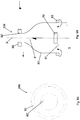
- Figures 6A and 6B show diagrammatic views, respectively a plan and a sectional view, of a component of the apparatus of the present invention according to a third embodiment thereof.
- Equal reference numerals refer to equal or similar elements.
- an apparatus for degrading the organic fraction of a liquid, in particular sewage, by means of active biomass, in particular active sludge particles, comprising:
- EPSs Extra-cellular Polymeric Substances
- the air delivery means 7, 70 preferably comprise one or more porous diffusers.
- the flow of sewage from the first opening to the one or more second openings 62 is obtained by virtue of the rising of the insufflated bubbles and therefore of the ascending motion of the liquid.
- the at least one first opening 61 faces towards the bottom of the tank, in the proximity of which the air delivery means 7, 70 are arranged.
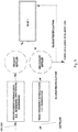
- the apparatus comprises an oxidation tank 1 or reactor.
- the oxidation tank may be obtained by modifying an existing tank.
- the apparatus, or plant comprises a tank 1 containing a fluid to be oxidized, typically waste water or organic waste fraction, upon grinding and dilution, or surplus sludge, i.e. in excess, to be subjected to digestion processes.
- a fluid to be oxidized typically waste water or organic waste fraction
- sludge i.e. in excess
- An inlet pipe 2 for the fluid to be treated is provided, preferably arranged at one side of the tank 1.
- the treated fluid outlet pipe 3 is preferably arranged at the opposite side of the tank 1 with respect to the inlet pipe 2, so as to create a flow of the fluid to be treated, avoiding hydraulic short-circuits.
- a deflector or partition 4 is provided, arranged in the final part of the tank 1, proximal to the outlet pipe 3.
- the lower end of the deflector 4 is spaced from the bottom of the tank.
- the deflector 4 is arranged so as to be spaced from the wall 31.
- the deflector 4 is inclined with respect to the wall 31, so that the end of the deflector 4 proximal to the bottom of the tank is spaced from the wall 31 by a distance smaller than the distance between the end of the distal deflector from the bottom of the tank and the wall 31.
- the deflector is substantially perpendicular to the bottom of the tank.
- the deflector 4 has the function of ensuring that the withdrawal of the purified outflow occurs at the lower part of the tank, where there is the lower concentration of EPSs, in particular the hydrophobic ones, which are concentrated in the upper part of the tank, since they tend to arrange themselves along the liquid-air interface and therefore on the surface.
- the forced ascending flow ensures that the sludge which separates in such space 55, delimited by the deflector 4 and by the wall 31, has a filtering effect on the ascending liquid flow which takes place towards the outlet pipe 3.
- EPSs are produced by virtue of stress events and cell lysis resulting from the use of the structures 6.
- each structure 6 is hollow. In particular, it delimits a circumscribed volume inside the tank 1, and the structure 6 is arranged in a condition partially or totally immersed in the tank 1.
- Each of the two structures 6 is substantially bell-shaped.
- the structures 6 are partially immersed in the tank 1 and maintained in a floating condition, by virtue of the presence of one or more floaters 60 preferably arranged on the top thereof.
- the structures are in a fixed position, preferably fastened to the bottom of the tank, by means of fastening means, for example a fastening structure.
- fastening means for example a fastening structure.
- the structures are suspended, being supported by one or more supporting structures.
- the side wall 67 of the structure 6, delimits an inlet opening 61 for letting in the fluid.
- the opening 61 is delimited by a lower end of the side wall 67 of the structure 6.
- the inlet opening 61 faces towards the bottom of the tank.
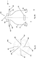
- At least two pipes preferably four pipes 65, are provided, for letting out the fluid.
- the pipes communicate with the inside of the structure 6 and each end of the pipes delimits a respective outlet opening 62 for the fluid, in particular for the air/liquid mixture, i.e., the air/sewage mixture.
- the pipes 65 extend transversally, for example orthogonally, with respect to the side wall 67 of the bell 6.
- the shape of the bell 6 provides that the area of the fluid inlet opening 61 is much greater than the area of each fluid outlet opening 62 or than the sum of the areas of the fluid outlet openings 62.
- the ratio between the area of the section of the inlet opening 61 and the area of the section of each outlet opening 62, or between the area of the section of the inlet opening 61 and the sum of the areas of the outlet openings 62 is at least 5:1, preferably between 100:10 and 100:1, according to the oxidation requirements.
- substantially bell-shaped structures 6, also called bells 6, may convey the air delivered into the tank by means of air delivery elements 70, for example porous diffusers, positioned in the lower part of the tank, connected, by means of tubings, to an air delivery system 7, partially illustrated, of the tank 1. It should be noted that the air may be introduced into the fluid contained in the tank 1 by means known to the skilled in the art.
- air delivery elements 70 for example porous diffusers
- the air may be introduced into the fluid contained in the tank 1 by means known to the skilled in the art.
- each bell 6 may include, inside, preferably fastened thereto, one or more air diffusers 70 which may be connected to the air delivery system 7.
- the bells 6 are arranged so that at least one delivery element 70, or diffuser, is provided, at each single bell 6, preferably inside thereof.
- the arrangement is such that the diffusers 70 create inside the bell 6 a water and air mixture which passes through the latter creating a flow from the opening 61 to the openings 62, for example, substantially from the bottom upwards, as illustrated in the Figure.
- the floating body 60 is provided on the upper part of the bell 6, adapted to support it in a floating condition (i.e., detached from the bottom of the tank 1).
- a ballast body 63 is preferably provided at the lower part of the bell 6, so as to ensure the vertical positioning of the bell 6 inside the tank 1.
- FIG. 2 an apparatus according to another embodiment of the invention is diagrammatically shown.
- the apparatus comprises an oxidation tank 1 or reactor.
- oxidation tank 1 or reactor For illustrative clarity, equal parts will have equal names and the detailed description thereof is omitted hereby because given earlier and valid also for this embodiment.
- the embodiment shown in this Figure differs from the preceding one in that it provides for one or more intermediate partitions or walls 10 (only one thereof being shown in the Figure) arranged in the tank 1.
- the partitions 10 are provided with a passage gap in the lower part thereof, or in other words, the lower end of each partition 10 is spaced from the bottom of the tank.
- the partitions 10 are oriented so as to extend in a direction substantially perpendicular to the bottom of the tank.
- the distance between the lower end of each partition 10 and the bottom wall of the tank is typically identified based on the hydraulic flows of the system, and varies between 10 cm and 1.5 m.
- each partition 10 is fastened to two opposite walls of the tank.
- each compartment 10 comprises at least one bell 6.
- each compartment may comprise one or more bells 6. Therefore, a sequence of compartments defined by the partitions 10, which may be characterized by different concentrations of EPSs, is achieved.
- a tubing 50 may be present, for recirculating the lighter sludge and the hydrophobic EPSs, which are therefore located in the proximity of or at the surface of the mixture to be treated.
- the tubing 50 comprises an inlet section or opening 51 arranged so as to channel inside it lighter sludge and/or hydrophobic EPSs from the surface of the mixture.
- the inlet opening 51 faces upwards, and the end of the tubing 50 is below the free surface of the fluid.
- the tubing 50 flows into a compartment which is upstream, from the hydraulic point of view, with respect to that in which the inlet section 51 of the tubing 50 is provided.
- the recirculation is typically performed by means of the depression created following the insufflation of air at the air inlet point or opening 52 in the ascending line portion of the tubing 50, i.e. where the fluid is directed upwards.
- a pipe 53 connects the tubing 50, at the air inlet point 52, to the air delivery system 70.
- the final part of the tank 1 i.e., downstream of the hydraulic circulation
- a zone 55 of partial calm during the operation of the apparatus, in which the separation of the liquid phase from the sludge phase, by means of sedimentation and filtering, and the formation of a fluid layer of granular sludge 5, capable of physically filtering the hydraulic flow exiting the reactor, occur.
- Such zone 55 is preferably delimited by the deflector 4 and by the wall 31 of the tank, which delimit a lower opening.
- the partition may be substantially perpendicular to the bottom of the tank or inclined.
- the granular sludge layer ensures the filtering of the effluent as well as ensuring a greater permanence of the EPSs in the tank, since, naturally or following the flotation produced by the air bubbles, they tend to arrange themselves in the upper part of the tank, or of the compartment where such deflector 4 is positioned.
- the hydrophobic component of the EPSs is arranged in the upper part of the tank.
- the presence of the deflector 4 and of the fluid granular sludge 5 bed also allows to retain inside the tank floating substances and "ash" formed during the cell lysis step, preventing them from being drifted towards the outlet pipe 3 in the outflow.
- the flotation thereof is also facilitated by the delivery of micro-bubbles of air inside the tank.
- the presence of the primary settler, upstream of the tank 1, is not required. Furthermore, given the capacity of the granular sludge to perform nitrification and denitrification inside the sludge granule itself, the presence of the denitrification compartment may no longer be required.
- the bell 6 preferably has a ratio between the inlet section 61, or area of the inlet opening 61, and the outlet section 62, or area of the outlet openings 62, of the liquid which may vary preferably from 100:1 to 100:10 in accordance with the oxidation potential required.
- the total outlet surface is given by the sum of the areas of the openings 62.
- the possibility of varying the aforesaid areas reduction ratio by means of respective adjustment devices 64 located directly in the outlet pipes 65 (better described below) of the water-air mixture is provided.
- Such adjustment devices 64 preferably, operate by varying the internal section of each pipe 65.
- the aforesaid ratio between the areas may therefore be varied, still remaining of at least 5:1, preferably between the limits 100:1 - 100:10.
- the same result may be obtained by means of a single centralized adjustment device mounted on the top of the bell (not shown in these figures).
- a similar result may be obtained by adjusting the flow rate of the air insufflated in the diffuser/s 70.
- the bell 6 has a lower edge which is preferably circular, which delimits the opening 61 (inlet section) for letting in the liquid.
- a ballast 63 for stabilizing the bell 6 is fastened to the edge.
- the floater 60 is arranged and configured so that the bell 6 is partially or totally submerged, in particular, in its development, and that the pipes 65 are preferably located beneath the free surface of the fluid (see Figures 1 and 2 ). It should be noted that a skilled in the art is capable of determining the features and the position of the floater to obtain such result.
- the lower end of the bell is arranged at a distance between 30 cm and 1 m from the bottom of the tank.
- the internal diameter D of the bell at the lower section 61 depends on the size of the tank and on the features of the sewage to be purified.
- the internal diameter of the bell 6 at the lower section 61 is of between 0.5 m and 5 m.
- At the top part of the bell 6 at least one outlet pipe 65 is provided, which delimits a respective opening 62.
- two or four outlet pipes 65 may be provided.
- Each outlet pipe 65 branches off from the top portion of the bell, which has an internal diameter smaller than the internal diameter of the section 61.
- each outlet pipe 65 extends from the side wall 67 of the bell 6, in a direction substantially perpendicular to the vertical axis X of the respective bell 6.
- each outlet pipe 65 is aligned two by two, so as to substantially form a cross.
- the internal diameter D of each outlet pipe 65, and of the respective opening 62 is between 5 and 20 cm.
- each outlet pipe 65 is arranged beneath the free surface of the liquid in the tank and at a distance from the free surface of the liquid of between 5 and 100 cm.
- the total outlet surface is given by the sum of the areas of each outlet section 62, net of any constrictions made to operate the aforesaid flow rate adjustment.
- the bell 6 is configured to float.
- the bell may be provided that the bell rests or is anchored to the bottom of the tank.
- the bell may provide for special support bases (not shown in the Figure).
- the bell 106 is devoid of any device for the adjustment of the exiting flow rate, i.e., the devices 64 of the preceding embodiment.
- the bell 106 has a water-air mixture inlet 61 and outlet 62 sections ratio which is established as constant, i.e., not variable during operation.
- such ratio between the inlet 61 and outlet 62 surfaces of the sewage is established during the step of constructing the bell 6 and is at least of 5:1, or in other words, the area of the first opening 61 is at least 5 times greater than the area of the second opening 62.
- the ratio between the area of the first opening 61 and the area of the second opening 62 is of between 100:1 and 100:10, in accordance with the oxidation potential required.
- the superoxidation potential of the bell may be adjusted by varying the amount of air insufflated by means of the diffuser/s 70.
- the outlet pipes 65 are preferably located beneath the free surface of the liquid ( Figures 1 and 2 ) and have the function of facilitating the mixing of the mixture by conveying the flow away from the bell 106.
- the lower end of the bell is preferably arranged at a distance between 30 cm and 1 m from the bottom of the tank.
- the internal diameter D of the bell 106 at the lower section 61 depends on the size of the tank and on the features of the sewage to be purified.
- the internal diameter D of the bell 6 at the lower section 61 is of between 0.5 m and 5 m.
- At the top part of the bell 106 at least one outlet pipe 65 for the mixture is provided, which delimits a respective opening 62.
- two or four outlet pipes 65 may be provided.
- Each outlet pipe 65 branches off from the top portion of the bell, which has an internal diameter smaller than the internal diameter of the section 61.
- each outlet pipe 65 extends in a direction substantially perpendicular to the vertical axis X of the respective bell 6.
- the internal diameter D of each outlet pipe 65 is between 5 and 20 cm.
- the total outlet surface is given by the sum of the areas of the openings 62.
- the bell may rest on the bottom of the tank, being provided with dedicated support bases.
- FIG. 6A a third embodiment of an oxidation bell 206 is diagrammatically shown.
- the bell does not have the outlet pipes previously described.
- the bell 206 is provided with an opening 62', opposite to the lower opening 61.
- the upper edge of the bell which delimits the opening 62' has an internal diameter smaller than the internal diameter D of the lower edge of the bell 206, which delimits the lower opening 61.
- this embodiment provides that the ratio between the inlet section 61 and the outlet section 62 of the liquid is at least of 5:1, preferably of between 100:1 and 100:10.
- the upper outlet surface 62 of the water/air mixture is preferably located, also in this case, beneath the free surface of the mixture.
- the superoxidation potential of the bell may be adjusted by varying the amount of air insufflated by means of the diffuser/s 70.
- the Figures show a floating application.
- the bell may rest on the bottom of the tank by means of special support bases (not shown in the Figures).
- the structures may also have a different shape, for example frustoconical.
- the system of the present invention has many advantages.
- the organic substance may be degraded in aqueous solution by means of a suspension-cultured aerobic granular sludge system characterized by reduced energy costs and high speed of separation between the active sludge and the purified water.
- the system may be easily adapted for modifying existing active sludge purification plants.
- an aqueous phase system for the low-cost oxidation of the organic waste fraction may be constituted.
- the chemical and biochemical oxidation of strongly polluting sewage of organic origin may be allowed.
- the surplus sludge may be transformed into EPSs inside the oxidation tanks of active sludge purification plants or in the aerobic digestion tanks of the sludge of the same plants.
- the surplus sludge of active sludge purification plants may be provided with better mechanical dehydration conditions by virtue of the presence of EPSs which favor the flocculation of sludge and therefore a reduced use of thickening products.
Landscapes
- Life Sciences & Earth Sciences (AREA)
- Chemical & Material Sciences (AREA)
- Water Supply & Treatment (AREA)
- Hydrology & Water Resources (AREA)
- Engineering & Computer Science (AREA)
- Environmental & Geological Engineering (AREA)
- Microbiology (AREA)
- Biodiversity & Conservation Biology (AREA)
- Organic Chemistry (AREA)
- Chemical Kinetics & Catalysis (AREA)
- Biological Treatment Of Waste Water (AREA)
- Aeration Devices For Treatment Of Activated Polluted Sludge (AREA)
- Activated Sludge Processes (AREA)
- Electrical Discharge Machining, Electrochemical Machining, And Combined Machining (AREA)
Priority Applications (2)
| Application Number | Priority Date | Filing Date | Title |
|---|---|---|---|
| PL18709076T PL3580183T3 (pl) | 2017-02-07 | 2018-02-07 | Urządzenie do oczyszczania ścieków |
| RS20210006A RS61376B1 (sr) | 2017-02-07 | 2018-02-07 | Uređaj za obradu otpadnih voda |
Applications Claiming Priority (2)
| Application Number | Priority Date | Filing Date | Title |
|---|---|---|---|
| IT102017000013252A IT201700013252A1 (it) | 2017-02-07 | 2017-02-07 | Apparato per il trattamento di fluidi inquinati |
| PCT/IB2018/050752 WO2018146597A1 (en) | 2017-02-07 | 2018-02-07 | Device for sewage treatment |
Publications (2)
| Publication Number | Publication Date |
|---|---|
| EP3580183A1 EP3580183A1 (en) | 2019-12-18 |
| EP3580183B1 true EP3580183B1 (en) | 2020-10-21 |
Family
ID=59067755
Family Applications (1)
| Application Number | Title | Priority Date | Filing Date |
|---|---|---|---|
| EP18709076.6A Active EP3580183B1 (en) | 2017-02-07 | 2018-02-07 | Device for sewage treatment |
Country Status (21)
| Country | Link |
|---|---|
| US (1) | US11643346B2 (es) |
| EP (1) | EP3580183B1 (es) |
| JP (1) | JP7110212B2 (es) |
| CN (1) | CN110573463B (es) |
| AU (1) | AU2018218560B2 (es) |
| BR (1) | BR112019016234B1 (es) |
| CA (1) | CA3051042A1 (es) |
| CO (1) | CO2019009616A2 (es) |
| DK (1) | DK3580183T3 (es) |
| EA (1) | EA039911B1 (es) |
| ES (1) | ES2843200T3 (es) |
| HU (1) | HUE053031T2 (es) |
| IT (1) | IT201700013252A1 (es) |
| MA (1) | MA47462B1 (es) |
| MD (1) | MD3580183T2 (es) |
| MX (1) | MX2019009328A (es) |
| PL (1) | PL3580183T3 (es) |
| PT (1) | PT3580183T (es) |
| RS (1) | RS61376B1 (es) |
| WO (1) | WO2018146597A1 (es) |
| ZA (1) | ZA201905904B (es) |
Families Citing this family (1)
| Publication number | Priority date | Publication date | Assignee | Title |
|---|---|---|---|---|
| IT202000001711A1 (it) * | 2020-01-29 | 2021-07-29 | Novideas S R L | Struttura per il trattamento di liquidi inquinati |
Family Cites Families (11)
| Publication number | Priority date | Publication date | Assignee | Title |
|---|---|---|---|---|
| US2077907A (en) * | 1935-05-14 | 1937-04-20 | Underpinning & Foundation Comp | Means for treating sewage, industrial wastes, and the like |
| DE2844934C2 (de) * | 1978-10-16 | 1980-07-10 | Josef Eckart & Soehne, 8351 Schaufling | Vorrichtung zum Belüften von Gülle o.dgl |
| AT392261B (de) * | 1985-05-31 | 1991-02-25 | Goerlich Franz Ing | Abwasserklaeranlage |
| SU1613437A1 (ru) * | 1988-03-17 | 1990-12-15 | Ростовский инженерно-строительный институт | Аэротенк |
| JPH0688031B2 (ja) * | 1989-12-05 | 1994-11-09 | 新日本製鐵株式会社 | 生物学的処理方法 |
| JPH06226292A (ja) * | 1993-02-04 | 1994-08-16 | Nippon Steel Corp | 生物学的汚水処理装置 |
| US5441634A (en) * | 1993-07-06 | 1995-08-15 | Edwards Laboratories, Inc. | Apparatus and method of circulating a body of fluid containing a mixture of solid waste and water and separating them |
| JP2000176485A (ja) * | 1998-12-21 | 2000-06-27 | Norihiko Hirano | 水流分散板及び該水流分散板を備えた静水域用浄化装置 |
| JP2006136783A (ja) * | 2004-11-11 | 2006-06-01 | Ishikawajima Harima Heavy Ind Co Ltd | 排水処理装置及び排水処理方法 |
| JP5918544B2 (ja) * | 2012-01-13 | 2016-05-18 | 有限会社山口ティー・エル・オー | 液膜式酸素供給装置 |
| CN106219745B (zh) * | 2016-09-20 | 2019-10-15 | 河海大学 | 一种节能型快速启动好氧颗粒污泥反应器 |
-
2017
- 2017-02-07 IT IT102017000013252A patent/IT201700013252A1/it unknown
-
2018
- 2018-02-07 MA MA47462A patent/MA47462B1/fr unknown
- 2018-02-07 MD MDE20191380T patent/MD3580183T2/ro unknown
- 2018-02-07 CA CA3051042A patent/CA3051042A1/en active Pending
- 2018-02-07 DK DK18709076.6T patent/DK3580183T3/da active
- 2018-02-07 MX MX2019009328A patent/MX2019009328A/es unknown
- 2018-02-07 WO PCT/IB2018/050752 patent/WO2018146597A1/en active Search and Examination
- 2018-02-07 BR BR112019016234-8A patent/BR112019016234B1/pt active IP Right Grant
- 2018-02-07 CN CN201880010440.1A patent/CN110573463B/zh active Active
- 2018-02-07 US US16/479,577 patent/US11643346B2/en active Active
- 2018-02-07 PL PL18709076T patent/PL3580183T3/pl unknown
- 2018-02-07 ES ES18709076T patent/ES2843200T3/es active Active
- 2018-02-07 PT PT187090766T patent/PT3580183T/pt unknown
- 2018-02-07 HU HUE18709076A patent/HUE053031T2/hu unknown
- 2018-02-07 AU AU2018218560A patent/AU2018218560B2/en active Active
- 2018-02-07 EA EA201991858A patent/EA039911B1/ru unknown
- 2018-02-07 JP JP2019541771A patent/JP7110212B2/ja active Active
- 2018-02-07 EP EP18709076.6A patent/EP3580183B1/en active Active
- 2018-02-07 RS RS20210006A patent/RS61376B1/sr unknown
-
2019
- 2019-09-04 CO CONC2019/0009616A patent/CO2019009616A2/es unknown
- 2019-09-06 ZA ZA2019/05904A patent/ZA201905904B/en unknown
Non-Patent Citations (1)
| Title |
|---|
| None * |
Also Published As
| Publication number | Publication date |
|---|---|
| JP7110212B2 (ja) | 2022-08-01 |
| CO2019009616A2 (es) | 2020-01-17 |
| CA3051042A1 (en) | 2018-08-16 |
| CN110573463B (zh) | 2022-04-08 |
| MX2019009328A (es) | 2019-12-11 |
| HUE053031T2 (hu) | 2021-06-28 |
| EA201991858A1 (ru) | 2020-02-03 |
| US20210363038A1 (en) | 2021-11-25 |
| MA47462A (fr) | 2019-12-18 |
| AU2018218560B2 (en) | 2023-05-18 |
| EP3580183A1 (en) | 2019-12-18 |
| AU2018218560A1 (en) | 2019-09-26 |
| IT201700013252A1 (it) | 2018-08-07 |
| PL3580183T3 (pl) | 2021-07-26 |
| WO2018146597A1 (en) | 2018-08-16 |
| ES2843200T3 (es) | 2021-07-16 |
| DK3580183T3 (da) | 2021-01-11 |
| BR112019016234B1 (pt) | 2023-10-10 |
| CN110573463A (zh) | 2019-12-13 |
| JP2020514032A (ja) | 2020-05-21 |
| MA47462B1 (fr) | 2021-02-26 |
| US11643346B2 (en) | 2023-05-09 |
| BR112019016234A2 (pt) | 2020-04-07 |
| ZA201905904B (en) | 2021-02-24 |
| EA039911B1 (ru) | 2022-03-25 |
| PT3580183T (pt) | 2021-01-12 |
| RS61376B1 (sr) | 2021-02-26 |
| MD3580183T2 (ro) | 2021-03-31 |
Similar Documents
| Publication | Publication Date | Title |
|---|---|---|
| EP2254842B1 (en) | Method and device for the treatment of waste water | |
| US6048459A (en) | Method and apparatus for fluidization of particulate bed materials | |
| CN102173510B (zh) | 具有snd脱氮功能的污泥无回流装置及其运行控制方法 | |
| US5534141A (en) | Wastewater treatment system with in-pond clarifier | |
| CN110510815A (zh) | 基于同时硝化反硝化的一体化污水处理装置及污水处理方法 | |
| EP3580183B1 (en) | Device for sewage treatment | |
| CN105884152A (zh) | Ifbr-uasb-a/obr处理化工废水组合工艺 | |
| JP5786998B1 (ja) | 有機性排水の生物処理方法及び装置 | |
| CN210505759U (zh) | 一种自循环高效生物脱氮装置 | |
| CN209835753U (zh) | 一种污水高效脱氮的生物膜反应器 | |
| CN105948411A (zh) | 一种新型工业废水处理工艺 | |
| US20180280907A1 (en) | Light particle or mixed particle system for wastewater treatment | |
| EP2488457B1 (en) | Anaerobic/aerobic liquid purification system and method therefor | |
| KR101634292B1 (ko) | 변형 a2o공법에 기반한 유동상여재 활용 수처리시스템 | |
| CN211644993U (zh) | 一种城镇生活污水一体化处理装置 | |
| KR101577063B1 (ko) | 폭기/침전 일체형 반응조를 구비한 하폐수 처리장치 | |
| CN105884151A (zh) | 新型组合工艺处理工业废水的方法 | |
| CN109485153A (zh) | 一种污水高效脱氮的生物膜反应器及方法 | |
| CN213202515U (zh) | 一种ifas-mbr污水深度处理装置 | |
| CN217709003U (zh) | 一种用于降解污水中有机物的生态系统 | |
| CN114988564B (zh) | 压力驱动旋流强化连续流好氧活性污泥颗粒化装置及方法 | |
| RU2758398C1 (ru) | Способ и установка биологической очистки стоков | |
| KR101761566B1 (ko) | 수처리 유용미생물 증폭장치 | |
| Brade et al. | Advances in the design of fine bubble aeration plants | |
| JPS5835118B2 (ja) | 廃水の生物学的処理のための二帯法 |
Legal Events
| Date | Code | Title | Description |
|---|---|---|---|
| STAA | Information on the status of an ep patent application or granted ep patent |
Free format text: STATUS: UNKNOWN |
|
| STAA | Information on the status of an ep patent application or granted ep patent |
Free format text: STATUS: THE INTERNATIONAL PUBLICATION HAS BEEN MADE |
|
| PUAI | Public reference made under article 153(3) epc to a published international application that has entered the european phase |
Free format text: ORIGINAL CODE: 0009012 |
|
| STAA | Information on the status of an ep patent application or granted ep patent |
Free format text: STATUS: REQUEST FOR EXAMINATION WAS MADE |
|
| 17P | Request for examination filed |
Effective date: 20190905 |
|
| AK | Designated contracting states |
Kind code of ref document: A1 Designated state(s): AL AT BE BG CH CY CZ DE DK EE ES FI FR GB GR HR HU IE IS IT LI LT LU LV MC MK MT NL NO PL PT RO RS SE SI SK SM TR |
|
| AX | Request for extension of the european patent |
Extension state: BA ME |
|
| GRAP | Despatch of communication of intention to grant a patent |
Free format text: ORIGINAL CODE: EPIDOSNIGR1 |
|
| STAA | Information on the status of an ep patent application or granted ep patent |
Free format text: STATUS: GRANT OF PATENT IS INTENDED |
|
| INTG | Intention to grant announced |
Effective date: 20200529 |
|
| GRAS | Grant fee paid |
Free format text: ORIGINAL CODE: EPIDOSNIGR3 |
|
| GRAA | (expected) grant |
Free format text: ORIGINAL CODE: 0009210 |
|
| STAA | Information on the status of an ep patent application or granted ep patent |
Free format text: STATUS: THE PATENT HAS BEEN GRANTED |
|
| AK | Designated contracting states |
Kind code of ref document: B1 Designated state(s): AL AT BE BG CH CY CZ DE DK EE ES FI FR GB GR HR HU IE IS IT LI LT LU LV MC MK MT NL NO PL PT RO RS SE SI SK SM TR |
|
| AX | Request for extension of the european patent |
Extension state: BA ME |
|
| REG | Reference to a national code |
Ref country code: GB Ref legal event code: FG4D |
|
| REG | Reference to a national code |
Ref country code: CH Ref legal event code: EP |
|
| REG | Reference to a national code |
Ref country code: IE Ref legal event code: FG4D |
|
| REG | Reference to a national code |
Ref country code: DE Ref legal event code: R096 Ref document number: 602018008969 Country of ref document: DE |
|
| REG | Reference to a national code |
Ref country code: AT Ref legal event code: REF Ref document number: 1325686 Country of ref document: AT Kind code of ref document: T Effective date: 20201115 |
|
| REG | Reference to a national code |
Ref country code: RO Ref legal event code: EPE |
|
| REG | Reference to a national code |
Ref country code: DK Ref legal event code: T3 Effective date: 20210108 |
|
| REG | Reference to a national code |
Ref country code: PT Ref legal event code: SC4A Ref document number: 3580183 Country of ref document: PT Date of ref document: 20210112 Kind code of ref document: T Free format text: AVAILABILITY OF NATIONAL TRANSLATION Effective date: 20210105 Ref country code: FI Ref legal event code: FGE |
|
| REG | Reference to a national code |
Ref country code: NL Ref legal event code: FP |
|
| REG | Reference to a national code |
Ref country code: SE Ref legal event code: TRGR |
|
| REG | Reference to a national code |
Ref country code: GR Ref legal event code: EP Ref document number: 20210400065 Country of ref document: GR Effective date: 20210215 |
|
| REG | Reference to a national code |
Ref country code: MA Ref legal event code: VAGR Ref document number: 47462 Country of ref document: MA Kind code of ref document: B1 |
|
| REG | Reference to a national code |
Ref country code: NO Ref legal event code: T2 Effective date: 20201021 |
|
| REG | Reference to a national code |
Ref country code: SK Ref legal event code: T3 Ref document number: E 36484 Country of ref document: SK |
|
| REG | Reference to a national code |
Ref country code: MD Ref legal event code: VAGR Ref document number: 3580183 Country of ref document: MD Date of ref document: 20210331 Kind code of ref document: T2 |
|
| REG | Reference to a national code |
Ref country code: LT Ref legal event code: MG4D |
|
| PG25 | Lapsed in a contracting state [announced via postgrant information from national office to epo] |
Ref country code: BG Free format text: LAPSE BECAUSE OF FAILURE TO SUBMIT A TRANSLATION OF THE DESCRIPTION OR TO PAY THE FEE WITHIN THE PRESCRIBED TIME-LIMIT Effective date: 20210121 Ref country code: LV Free format text: LAPSE BECAUSE OF FAILURE TO SUBMIT A TRANSLATION OF THE DESCRIPTION OR TO PAY THE FEE WITHIN THE PRESCRIBED TIME-LIMIT Effective date: 20201021 Ref country code: IS Free format text: LAPSE BECAUSE OF FAILURE TO SUBMIT A TRANSLATION OF THE DESCRIPTION OR TO PAY THE FEE WITHIN THE PRESCRIBED TIME-LIMIT Effective date: 20210221 |
|
| VSFP | Annual fee paid to validation state [announced via postgrant information from national office to epo] |
Ref country code: MD Payment date: 20210203 Year of fee payment: 4 |
|
| REG | Reference to a national code |
Ref country code: HU Ref legal event code: AG4A Ref document number: E053031 Country of ref document: HU |
|
| PG25 | Lapsed in a contracting state [announced via postgrant information from national office to epo] |
Ref country code: HR Free format text: LAPSE BECAUSE OF FAILURE TO SUBMIT A TRANSLATION OF THE DESCRIPTION OR TO PAY THE FEE WITHIN THE PRESCRIBED TIME-LIMIT Effective date: 20201021 |
|
| REG | Reference to a national code |
Ref country code: ES Ref legal event code: FG2A Ref document number: 2843200 Country of ref document: ES Kind code of ref document: T3 Effective date: 20210716 |
|
| REG | Reference to a national code |
Ref country code: DE Ref legal event code: R097 Ref document number: 602018008969 Country of ref document: DE |
|
| PG25 | Lapsed in a contracting state [announced via postgrant information from national office to epo] |
Ref country code: SM Free format text: LAPSE BECAUSE OF FAILURE TO SUBMIT A TRANSLATION OF THE DESCRIPTION OR TO PAY THE FEE WITHIN THE PRESCRIBED TIME-LIMIT Effective date: 20201021 Ref country code: EE Free format text: LAPSE BECAUSE OF FAILURE TO SUBMIT A TRANSLATION OF THE DESCRIPTION OR TO PAY THE FEE WITHIN THE PRESCRIBED TIME-LIMIT Effective date: 20201021 Ref country code: LT Free format text: LAPSE BECAUSE OF FAILURE TO SUBMIT A TRANSLATION OF THE DESCRIPTION OR TO PAY THE FEE WITHIN THE PRESCRIBED TIME-LIMIT Effective date: 20201021 |
|
| PLBE | No opposition filed within time limit |
Free format text: ORIGINAL CODE: 0009261 |
|
| STAA | Information on the status of an ep patent application or granted ep patent |
Free format text: STATUS: NO OPPOSITION FILED WITHIN TIME LIMIT |
|
| 26N | No opposition filed |
Effective date: 20210722 |
|
| PG25 | Lapsed in a contracting state [announced via postgrant information from national office to epo] |
Ref country code: MC Free format text: LAPSE BECAUSE OF FAILURE TO SUBMIT A TRANSLATION OF THE DESCRIPTION OR TO PAY THE FEE WITHIN THE PRESCRIBED TIME-LIMIT Effective date: 20201021 |
|
| PG25 | Lapsed in a contracting state [announced via postgrant information from national office to epo] |
Ref country code: LU Free format text: LAPSE BECAUSE OF NON-PAYMENT OF DUE FEES Effective date: 20210207 Ref country code: AL Free format text: LAPSE BECAUSE OF FAILURE TO SUBMIT A TRANSLATION OF THE DESCRIPTION OR TO PAY THE FEE WITHIN THE PRESCRIBED TIME-LIMIT Effective date: 20201021 |
|
| PG25 | Lapsed in a contracting state [announced via postgrant information from national office to epo] |
Ref country code: SI Free format text: LAPSE BECAUSE OF FAILURE TO SUBMIT A TRANSLATION OF THE DESCRIPTION OR TO PAY THE FEE WITHIN THE PRESCRIBED TIME-LIMIT Effective date: 20201021 |
|
| VSFP | Annual fee paid to validation state [announced via postgrant information from national office to epo] |
Ref country code: MD Payment date: 20220114 Year of fee payment: 5 |
|
| PG25 | Lapsed in a contracting state [announced via postgrant information from national office to epo] |
Ref country code: IS Free format text: LAPSE BECAUSE OF FAILURE TO SUBMIT A TRANSLATION OF THE DESCRIPTION OR TO PAY THE FEE WITHIN THE PRESCRIBED TIME-LIMIT Effective date: 20210221 |
|
| VSFP | Annual fee paid to validation state [announced via postgrant information from national office to epo] |
Ref country code: TN Payment date: 20210228 Year of fee payment: 4 |
|
| PGFP | Annual fee paid to national office [announced via postgrant information from national office to epo] |
Ref country code: NO Payment date: 20230309 Year of fee payment: 6 Ref country code: DK Payment date: 20230314 Year of fee payment: 6 |
|
| PGFP | Annual fee paid to national office [announced via postgrant information from national office to epo] |
Ref country code: TR Payment date: 20230320 Year of fee payment: 6 Ref country code: RS Payment date: 20230307 Year of fee payment: 6 Ref country code: IT Payment date: 20230328 Year of fee payment: 6 Ref country code: BE Payment date: 20230315 Year of fee payment: 6 |
|
| PG25 | Lapsed in a contracting state [announced via postgrant information from national office to epo] |
Ref country code: CY Free format text: LAPSE BECAUSE OF FAILURE TO SUBMIT A TRANSLATION OF THE DESCRIPTION OR TO PAY THE FEE WITHIN THE PRESCRIBED TIME-LIMIT Effective date: 20201021 |
|
| P01 | Opt-out of the competence of the unified patent court (upc) registered |
Effective date: 20230525 |
|
| REG | Reference to a national code |
Ref country code: AT Ref legal event code: UEP Ref document number: 1325686 Country of ref document: AT Kind code of ref document: T Effective date: 20201021 |
|
| REG | Reference to a national code |
Ref country code: MD Ref legal event code: KA4A Ref document number: 3580183 Country of ref document: MD Kind code of ref document: T2 |
|
| VSFP | Annual fee paid to validation state [announced via postgrant information from national office to epo] |
Ref country code: TN Payment date: 20220228 Year of fee payment: 5 |
|
| PGFP | Annual fee paid to national office [announced via postgrant information from national office to epo] |
Ref country code: SK Payment date: 20231227 Year of fee payment: 7 |
|
| PGFP | Annual fee paid to national office [announced via postgrant information from national office to epo] |
Ref country code: GB Payment date: 20231214 Year of fee payment: 7 |
|
| PGFP | Annual fee paid to national office [announced via postgrant information from national office to epo] |
Ref country code: SE Payment date: 20231213 Year of fee payment: 7 Ref country code: NL Payment date: 20231215 Year of fee payment: 7 Ref country code: IE Payment date: 20231211 Year of fee payment: 7 Ref country code: FR Payment date: 20231212 Year of fee payment: 7 Ref country code: FI Payment date: 20231219 Year of fee payment: 7 |
|
| VS25 | Lapsed in a validation state [announced via postgrant information from nat. office to epo] |
Ref country code: MD Free format text: LAPSE BECAUSE OF NON-PAYMENT OF DUE FEES Effective date: 20230207 |
|
| PGFP | Annual fee paid to national office [announced via postgrant information from national office to epo] |
Ref country code: PL Payment date: 20231116 Year of fee payment: 7 |
|
| PGFP | Annual fee paid to national office [announced via postgrant information from national office to epo] |
Ref country code: GR Payment date: 20240110 Year of fee payment: 7 |
|
| PGFP | Annual fee paid to national office [announced via postgrant information from national office to epo] |
Ref country code: ES Payment date: 20240305 Year of fee payment: 7 |
|
| PGFP | Annual fee paid to national office [announced via postgrant information from national office to epo] |
Ref country code: AT Payment date: 20240125 Year of fee payment: 7 |
|
| PG25 | Lapsed in a contracting state [announced via postgrant information from national office to epo] |
Ref country code: MK Free format text: LAPSE BECAUSE OF FAILURE TO SUBMIT A TRANSLATION OF THE DESCRIPTION OR TO PAY THE FEE WITHIN THE PRESCRIBED TIME-LIMIT Effective date: 20201021 |
|
| PGFP | Annual fee paid to national office [announced via postgrant information from national office to epo] |
Ref country code: RO Payment date: 20240112 Year of fee payment: 7 Ref country code: HU Payment date: 20240111 Year of fee payment: 7 Ref country code: DE Payment date: 20231212 Year of fee payment: 7 Ref country code: CZ Payment date: 20240118 Year of fee payment: 7 Ref country code: PT Payment date: 20240207 Year of fee payment: 7 Ref country code: CH Payment date: 20240301 Year of fee payment: 7 |