EP3579330A1 - Dispositif de refroidissement de batterie pour véhicule - Google Patents
Dispositif de refroidissement de batterie pour véhicule Download PDFInfo
- Publication number
- EP3579330A1 EP3579330A1 EP18203431.4A EP18203431A EP3579330A1 EP 3579330 A1 EP3579330 A1 EP 3579330A1 EP 18203431 A EP18203431 A EP 18203431A EP 3579330 A1 EP3579330 A1 EP 3579330A1
- Authority
- EP
- European Patent Office
- Prior art keywords
- refrigerant
- plate
- battery cells
- battery
- channel
- Prior art date
- Legal status (The legal status is an assumption and is not a legal conclusion. Google has not performed a legal analysis and makes no representation as to the accuracy of the status listed.)
- Pending
Links
Images


Classifications
-
- H—ELECTRICITY
- H01—ELECTRIC ELEMENTS
- H01M—PROCESSES OR MEANS, e.g. BATTERIES, FOR THE DIRECT CONVERSION OF CHEMICAL ENERGY INTO ELECTRICAL ENERGY
- H01M10/00—Secondary cells; Manufacture thereof
- H01M10/60—Heating or cooling; Temperature control
- H01M10/61—Types of temperature control
- H01M10/613—Cooling or keeping cold
-
- B—PERFORMING OPERATIONS; TRANSPORTING
- B60—VEHICLES IN GENERAL
- B60L—PROPULSION OF ELECTRICALLY-PROPELLED VEHICLES; SUPPLYING ELECTRIC POWER FOR AUXILIARY EQUIPMENT OF ELECTRICALLY-PROPELLED VEHICLES; ELECTRODYNAMIC BRAKE SYSTEMS FOR VEHICLES IN GENERAL; MAGNETIC SUSPENSION OR LEVITATION FOR VEHICLES; MONITORING OPERATING VARIABLES OF ELECTRICALLY-PROPELLED VEHICLES; ELECTRIC SAFETY DEVICES FOR ELECTRICALLY-PROPELLED VEHICLES
- B60L58/00—Methods or circuit arrangements for monitoring or controlling batteries or fuel cells, specially adapted for electric vehicles
- B60L58/10—Methods or circuit arrangements for monitoring or controlling batteries or fuel cells, specially adapted for electric vehicles for monitoring or controlling batteries
- B60L58/24—Methods or circuit arrangements for monitoring or controlling batteries or fuel cells, specially adapted for electric vehicles for monitoring or controlling batteries for controlling the temperature of batteries
- B60L58/26—Methods or circuit arrangements for monitoring or controlling batteries or fuel cells, specially adapted for electric vehicles for monitoring or controlling batteries for controlling the temperature of batteries by cooling
-
- F—MECHANICAL ENGINEERING; LIGHTING; HEATING; WEAPONS; BLASTING
- F28—HEAT EXCHANGE IN GENERAL
- F28D—HEAT-EXCHANGE APPARATUS, NOT PROVIDED FOR IN ANOTHER SUBCLASS, IN WHICH THE HEAT-EXCHANGE MEDIA DO NOT COME INTO DIRECT CONTACT
- F28D15/00—Heat-exchange apparatus with the intermediate heat-transfer medium in closed tubes passing into or through the conduit walls ; Heat-exchange apparatus employing intermediate heat-transfer medium or bodies
- F28D15/02—Heat-exchange apparatus with the intermediate heat-transfer medium in closed tubes passing into or through the conduit walls ; Heat-exchange apparatus employing intermediate heat-transfer medium or bodies in which the medium condenses and evaporates, e.g. heat pipes
- F28D15/0233—Heat-exchange apparatus with the intermediate heat-transfer medium in closed tubes passing into or through the conduit walls ; Heat-exchange apparatus employing intermediate heat-transfer medium or bodies in which the medium condenses and evaporates, e.g. heat pipes the conduits having a particular shape, e.g. non-circular cross-section, annular
-
- F—MECHANICAL ENGINEERING; LIGHTING; HEATING; WEAPONS; BLASTING
- F28—HEAT EXCHANGE IN GENERAL
- F28D—HEAT-EXCHANGE APPARATUS, NOT PROVIDED FOR IN ANOTHER SUBCLASS, IN WHICH THE HEAT-EXCHANGE MEDIA DO NOT COME INTO DIRECT CONTACT
- F28D9/00—Heat-exchange apparatus having stationary plate-like or laminated conduit assemblies for both heat-exchange media, the media being in contact with different sides of a conduit wall
- F28D9/0062—Heat-exchange apparatus having stationary plate-like or laminated conduit assemblies for both heat-exchange media, the media being in contact with different sides of a conduit wall the conduits for one heat-exchange medium being formed by spaced plates with inserted elements
-
- H—ELECTRICITY
- H01—ELECTRIC ELEMENTS
- H01M—PROCESSES OR MEANS, e.g. BATTERIES, FOR THE DIRECT CONVERSION OF CHEMICAL ENERGY INTO ELECTRICAL ENERGY
- H01M10/00—Secondary cells; Manufacture thereof
- H01M10/60—Heating or cooling; Temperature control
- H01M10/61—Types of temperature control
- H01M10/617—Types of temperature control for achieving uniformity or desired distribution of temperature
-
- H—ELECTRICITY
- H01—ELECTRIC ELEMENTS
- H01M—PROCESSES OR MEANS, e.g. BATTERIES, FOR THE DIRECT CONVERSION OF CHEMICAL ENERGY INTO ELECTRICAL ENERGY
- H01M10/00—Secondary cells; Manufacture thereof
- H01M10/60—Heating or cooling; Temperature control
- H01M10/62—Heating or cooling; Temperature control specially adapted for specific applications
- H01M10/625—Vehicles
-
- H—ELECTRICITY
- H01—ELECTRIC ELEMENTS
- H01M—PROCESSES OR MEANS, e.g. BATTERIES, FOR THE DIRECT CONVERSION OF CHEMICAL ENERGY INTO ELECTRICAL ENERGY
- H01M10/00—Secondary cells; Manufacture thereof
- H01M10/60—Heating or cooling; Temperature control
- H01M10/64—Heating or cooling; Temperature control characterised by the shape of the cells
- H01M10/647—Prismatic or flat cells, e.g. pouch cells
-
- H—ELECTRICITY
- H01—ELECTRIC ELEMENTS
- H01M—PROCESSES OR MEANS, e.g. BATTERIES, FOR THE DIRECT CONVERSION OF CHEMICAL ENERGY INTO ELECTRICAL ENERGY
- H01M10/00—Secondary cells; Manufacture thereof
- H01M10/60—Heating or cooling; Temperature control
- H01M10/65—Means for temperature control structurally associated with the cells
- H01M10/653—Means for temperature control structurally associated with the cells characterised by electrically insulating or thermally conductive materials
-
- H—ELECTRICITY
- H01—ELECTRIC ELEMENTS
- H01M—PROCESSES OR MEANS, e.g. BATTERIES, FOR THE DIRECT CONVERSION OF CHEMICAL ENERGY INTO ELECTRICAL ENERGY
- H01M10/00—Secondary cells; Manufacture thereof
- H01M10/60—Heating or cooling; Temperature control
- H01M10/65—Means for temperature control structurally associated with the cells
- H01M10/655—Solid structures for heat exchange or heat conduction
- H01M10/6551—Surfaces specially adapted for heat dissipation or radiation, e.g. fins or coatings
-
- H—ELECTRICITY
- H01—ELECTRIC ELEMENTS
- H01M—PROCESSES OR MEANS, e.g. BATTERIES, FOR THE DIRECT CONVERSION OF CHEMICAL ENERGY INTO ELECTRICAL ENERGY
- H01M10/00—Secondary cells; Manufacture thereof
- H01M10/60—Heating or cooling; Temperature control
- H01M10/65—Means for temperature control structurally associated with the cells
- H01M10/655—Solid structures for heat exchange or heat conduction
- H01M10/6554—Rods or plates
-
- H—ELECTRICITY
- H01—ELECTRIC ELEMENTS
- H01M—PROCESSES OR MEANS, e.g. BATTERIES, FOR THE DIRECT CONVERSION OF CHEMICAL ENERGY INTO ELECTRICAL ENERGY
- H01M10/00—Secondary cells; Manufacture thereof
- H01M10/60—Heating or cooling; Temperature control
- H01M10/65—Means for temperature control structurally associated with the cells
- H01M10/655—Solid structures for heat exchange or heat conduction
- H01M10/6556—Solid parts with flow channel passages or pipes for heat exchange
-
- H—ELECTRICITY
- H01—ELECTRIC ELEMENTS
- H01M—PROCESSES OR MEANS, e.g. BATTERIES, FOR THE DIRECT CONVERSION OF CHEMICAL ENERGY INTO ELECTRICAL ENERGY
- H01M10/00—Secondary cells; Manufacture thereof
- H01M10/60—Heating or cooling; Temperature control
- H01M10/65—Means for temperature control structurally associated with the cells
- H01M10/656—Means for temperature control structurally associated with the cells characterised by the type of heat-exchange fluid
- H01M10/6567—Liquids
-
- H—ELECTRICITY
- H01—ELECTRIC ELEMENTS
- H01M—PROCESSES OR MEANS, e.g. BATTERIES, FOR THE DIRECT CONVERSION OF CHEMICAL ENERGY INTO ELECTRICAL ENERGY
- H01M10/00—Secondary cells; Manufacture thereof
- H01M10/60—Heating or cooling; Temperature control
- H01M10/65—Means for temperature control structurally associated with the cells
- H01M10/656—Means for temperature control structurally associated with the cells characterised by the type of heat-exchange fluid
- H01M10/6569—Fluids undergoing a liquid-gas phase change or transition, e.g. evaporation or condensation
-
- H—ELECTRICITY
- H01—ELECTRIC ELEMENTS
- H01M—PROCESSES OR MEANS, e.g. BATTERIES, FOR THE DIRECT CONVERSION OF CHEMICAL ENERGY INTO ELECTRICAL ENERGY
- H01M50/00—Constructional details or processes of manufacture of the non-active parts of electrochemical cells other than fuel cells, e.g. hybrid cells
- H01M50/20—Mountings; Secondary casings or frames; Racks, modules or packs; Suspension devices; Shock absorbers; Transport or carrying devices; Holders
- H01M50/204—Racks, modules or packs for multiple batteries or multiple cells
- H01M50/207—Racks, modules or packs for multiple batteries or multiple cells characterised by their shape
- H01M50/209—Racks, modules or packs for multiple batteries or multiple cells characterised by their shape adapted for prismatic or rectangular cells
-
- B—PERFORMING OPERATIONS; TRANSPORTING
- B60—VEHICLES IN GENERAL
- B60Y—INDEXING SCHEME RELATING TO ASPECTS CROSS-CUTTING VEHICLE TECHNOLOGY
- B60Y2200/00—Type of vehicle
- B60Y2200/90—Vehicles comprising electric prime movers
- B60Y2200/91—Electric vehicles
-
- B—PERFORMING OPERATIONS; TRANSPORTING
- B60—VEHICLES IN GENERAL
- B60Y—INDEXING SCHEME RELATING TO ASPECTS CROSS-CUTTING VEHICLE TECHNOLOGY
- B60Y2306/00—Other features of vehicle sub-units
- B60Y2306/05—Cooling
-
- F—MECHANICAL ENGINEERING; LIGHTING; HEATING; WEAPONS; BLASTING
- F28—HEAT EXCHANGE IN GENERAL
- F28D—HEAT-EXCHANGE APPARATUS, NOT PROVIDED FOR IN ANOTHER SUBCLASS, IN WHICH THE HEAT-EXCHANGE MEDIA DO NOT COME INTO DIRECT CONTACT
- F28D21/00—Heat-exchange apparatus not covered by any of the groups F28D1/00 - F28D20/00
- F28D2021/0019—Other heat exchangers for particular applications; Heat exchange systems not otherwise provided for
- F28D2021/0028—Other heat exchangers for particular applications; Heat exchange systems not otherwise provided for for cooling heat generating elements, e.g. for cooling electronic components or electric devices
-
- F—MECHANICAL ENGINEERING; LIGHTING; HEATING; WEAPONS; BLASTING
- F28—HEAT EXCHANGE IN GENERAL
- F28D—HEAT-EXCHANGE APPARATUS, NOT PROVIDED FOR IN ANOTHER SUBCLASS, IN WHICH THE HEAT-EXCHANGE MEDIA DO NOT COME INTO DIRECT CONTACT
- F28D21/00—Heat-exchange apparatus not covered by any of the groups F28D1/00 - F28D20/00
- F28D2021/0019—Other heat exchangers for particular applications; Heat exchange systems not otherwise provided for
- F28D2021/008—Other heat exchangers for particular applications; Heat exchange systems not otherwise provided for for vehicles
-
- F—MECHANICAL ENGINEERING; LIGHTING; HEATING; WEAPONS; BLASTING
- F28—HEAT EXCHANGE IN GENERAL
- F28F—DETAILS OF HEAT-EXCHANGE AND HEAT-TRANSFER APPARATUS, OF GENERAL APPLICATION
- F28F3/00—Plate-like or laminated elements; Assemblies of plate-like or laminated elements
- F28F3/02—Elements or assemblies thereof with means for increasing heat-transfer area, e.g. with fins, with recesses, with corrugations
-
- H—ELECTRICITY
- H01—ELECTRIC ELEMENTS
- H01M—PROCESSES OR MEANS, e.g. BATTERIES, FOR THE DIRECT CONVERSION OF CHEMICAL ENERGY INTO ELECTRICAL ENERGY
- H01M2220/00—Batteries for particular applications
- H01M2220/20—Batteries in motive systems, e.g. vehicle, ship, plane
-
- Y—GENERAL TAGGING OF NEW TECHNOLOGICAL DEVELOPMENTS; GENERAL TAGGING OF CROSS-SECTIONAL TECHNOLOGIES SPANNING OVER SEVERAL SECTIONS OF THE IPC; TECHNICAL SUBJECTS COVERED BY FORMER USPC CROSS-REFERENCE ART COLLECTIONS [XRACs] AND DIGESTS
- Y02—TECHNOLOGIES OR APPLICATIONS FOR MITIGATION OR ADAPTATION AGAINST CLIMATE CHANGE
- Y02E—REDUCTION OF GREENHOUSE GAS [GHG] EMISSIONS, RELATED TO ENERGY GENERATION, TRANSMISSION OR DISTRIBUTION
- Y02E60/00—Enabling technologies; Technologies with a potential or indirect contribution to GHG emissions mitigation
- Y02E60/10—Energy storage using batteries
-
- Y—GENERAL TAGGING OF NEW TECHNOLOGICAL DEVELOPMENTS; GENERAL TAGGING OF CROSS-SECTIONAL TECHNOLOGIES SPANNING OVER SEVERAL SECTIONS OF THE IPC; TECHNICAL SUBJECTS COVERED BY FORMER USPC CROSS-REFERENCE ART COLLECTIONS [XRACs] AND DIGESTS
- Y02—TECHNOLOGIES OR APPLICATIONS FOR MITIGATION OR ADAPTATION AGAINST CLIMATE CHANGE
- Y02T—CLIMATE CHANGE MITIGATION TECHNOLOGIES RELATED TO TRANSPORTATION
- Y02T10/00—Road transport of goods or passengers
- Y02T10/60—Other road transportation technologies with climate change mitigation effect
- Y02T10/70—Energy storage systems for electromobility, e.g. batteries
Definitions
- the present invention relates generally to a battery cooling device for a vehicle, and more particularly, to a battery cooling device for a vehicle, wherein the phase change of a refrigerant is used to maintain temperatures of battery cells of a battery module within a predetermined range.
- an electric vehicle requires long-distance driving, high-power/high-performance driving, and quick charging, and a battery system as an energy source of the electric vehicle has high levels of electric current flowing in battery cells thereof, which causes heat greater than the capacity of conventional battery cooling device applied to existing electric vehicles. Since the heat produced in the battery cells has an adverse effect on battery life, the heat is required to be maintained at a predetermined temperature range.
- the air cooling system provides air within a vehicle cabin to the battery system by using a cooling fan to cool the battery cells.
- the water cooling system provides a coolant cooled by an additional battery chiller in a front of the vehicle, the battery chiller operating in cooperation with a radiator or an air conditioner compressor, to the battery system by using a pump to cool the battery cells.
- an electric vehicle uses high levels of electric current for long-distance driving and high-power/high-performance driving, and accordingly even though the electric vehicle uses a water cooling system having cooling performance greater than cooling performance of an air cooling system, increasing the capacities of the air conditioner compressor (or the radiator) and the battery chiller to cool heat produced in the battery cells is unavoidable.
- the present invention provides a battery cooling device for a vehicle, wherein the battery cooling device generates a continuous phase change of the refrigerant within an entire area of a refrigerant channel having a refrigerant flowing for cooling a battery module, thereby maximizing a cooling performance of all battery cells of the battery module, and enabling cooling of the battery cells.
- the refrigerant evaporated by heat produced in the battery cells may be restored to a liquid refrigerant using a coolant, thereby maintaining an even cooling performance for the battery cells, from the battery cells disposed at an upper flow side in a flow direction of the refrigerant to the battery cells disposed at a lower flow side thereof, relative to the flow direction of the refrigerant.
- the present invention also provides a battery cooling device for a vehicle, wherein a pair of plate members having corrugated parts are used to configure a refrigerant plate having the refrigerant channel, thereby increasing heat exchange efficiency of the refrigerant flowing in the refrigerant channel, and improving manufacturing efficiency and rigidity of the refrigerant plate.
- a battery cooling device for a vehicle to cool a battery module composed of a plurality of battery cells may include: a refrigerant plate that extends in arranged directions of the plurality of battery cells and has a refrigerant flowing for cooling the plurality of battery cells; and a coolant plate arranged to enable heat exchange with the refrigerant plate, and having a coolant flowing for liquefying a refrigerant evaporated by heat produced in the battery cells.
- the refrigerant plate may include: a first plate member arranged to enable heat exchange with the plurality of battery cells; a second plate member arranged to enable heat exchange with the coolant plate; and a refrigerant channel disposed between the first plate member and the second plate member, and having the refrigerant flowing in the refrigerant channel.
- the first plate member may be disposed to be in contact with the plurality of battery cells to enable heat exchange therewith
- the second plate member may be disposed to be in contact with the coolant plate to enable heat exchange therewith
- the first plate member may include a first corrugated part having ridges and grooves on a surface of the first plate member which is not in contact with the plurality of battery cells
- the second plate member may include a second corrugated part having ridges and grooves on a surface of the second plate member which is not in contact with the coolant plate
- the first corrugated part and the second corrugated part may be spaced apart from each other at an interval corresponding to a width of the refrigerant channel.
- first plate member and the second plate member may be configured to be flat plates.
- the first corrugated part may include at least one fin that extends therefrom toward the refrigerant heating channel
- the second corrugated part may include at least one fin that extends therefrom toward the refrigerant cooling channel.
- the fin provided on the first corrugated part and the fin provided on the second corrugated part may be joined on surfaces of the first corrugated part and the second corrugated part respectively by any one joining method selected among furnace brazing, resistance welding, ultrasonic welding, and laser welding.
- the refrigerant channel may include a plurality of refrigerant heating channels in which the refrigerant is heated by heat exchange with the battery cells, and a plurality of refrigerant cooling channels in which the refrigerant is cooled by heat exchange with the coolant plate, each of the refrigerant heating channels and each of the refrigerant cooling channels being alternately arranged in the arranged directions of the battery cells.
- the refrigerant heating channel may be disposed between the battery cells and the coolant plate to neighbor (e.g., by proximate to) the battery cells, and the refrigerant cooling channel may be disposed between the battery cells and the coolant plate to neighbor the coolant plate.
- the refrigerant channel may include a refrigerant transfer channel arranged between the refrigerant heating channel and the refrigerant cooling channel.
- cell covers supporting the plurality of battery cells and the refrigerant plate may be in contact with each other via a first interface member made of a thermal interface material which enhance the cooling performance by filling the gap or air-filled pore space between the cell covers and the refrigerant plate.
- the coolant plate and the refrigerant plate may be in contact with each other via a second interface member made of a thermal interface material which enhance the cooling performance by filling the gap or air-filled pore space between the coolant plate and the refrigerant plate.
- the battery cooling device has the following advantages.
- the evaporated refrigerant may be restored to the liquid refrigerant.
- the liquid refrigerant in an entire area of the refrigerant channel may be used to cool the battery cells, and a cooling effect on the battery cells arranged in a flow direction of the refrigerant may be evenly maintained regardless of positions of the battery cells.
- cooling performance of the refrigerant for the battery cells may be evenly maintained from the battery cells arranged at an upper flow side of the flow direction to the battery cells arranged at a lower flow side thereof relative to the flow direction of the refrigerant, and thus the cooling effect on the battery cells may be prevented from decreasing in the flow direction of the refrigerant. Accordingly, it may be possible to maximize the cooling effect on all of the battery cells cooled by the refrigerant, and to cool the battery cells evenly.
- latent heat of vaporization produced during a phase change of the refrigerant from liquid to gas may be used to cool the battery cells, and thus cooling performance may be improved, compared to when a sensible heat of the refrigerant is used to cool the battery cells.
- cooling the battery cells by using the latent heat can have several times higher cooling effect than cooling the battery cells by using the sensible heat.
- a relatively minimal amount of the refrigerant may be used to maintain temperature of each of the battery cells within a predetermined range.
- vehicle or “vehicular” or other similar term as used herein is inclusive of motor vehicles in general such as passenger automobiles including sports utility vehicles (SUV), buses, trucks, various commercial vehicles, watercraft including a variety of boats and ships, aircraft, and the like, and includes hybrid vehicles, electric vehicles, plug-in hybrid electric vehicles, hydrogen-powered vehicles and other alternative fuel vehicles (e.g. fuels derived from resources other than petroleum).
- a hybrid vehicle is a vehicle that has two or more sources of power, for example both gasoline-powered and electric-powered vehicles.
- controller/control unit refers to a hardware device that includes a memory and a processor.
- the memory is configured to store the modules and the processor is specifically configured to execute said modules to perform one or more processes which are described further below.
- the refrigerant When a liquid refrigerant is used to cool a battery module as an energy source of an electric vehicle, the refrigerant absorbs heat produced in the battery module while flowing in a refrigerant channel, and cools the battery module. While being evaporated by heat produced in the battery module, the liquid refrigerant cools the battery module, and after evaporation of the liquid refrigerant, an evaporated refrigerant absorbs the heat of the battery module and cools the battery module.
- the difference between the first energy value and the second energy value may be different depending on the type of the refrigerant, the first energy value is around six times higher than the second energy value.
- the difference is caused due to cooling the battery module by using a phase change of the refrigerant without temperature change thereof is substantially greater in cooling performance than cooling the battery module by using the temperature change alone without the phase change of the refrigerant. Accordingly, a difference between an energy value in the unit of calorie absorbed from the battery module before the refrigerant is evaporated and an energy value in the unit of calorie absorbed therefrom after the refrigerant is evaporated occurs, and after the evaporation of the refrigerant, the cooling of the battery module is rarely performed.
- the refrigerant in an evaporated state has even less cooling performance than the refrigerant in a liquid state. Further, since even after the refrigerant turns to the evaporated refrigerant, the evaporated refrigerant is heated by heat produced in the battery cells, it is difficult for the evaporated refrigerant to restore to an original phase.
- a battery cooling device for a vehicle is configured to have a battery cooling structure capable of restoring the evaporated refrigerant to the liquid refrigerant to maximize a cooling effect on the battery cells of the battery module, and to enable the even cooling of the battery cells.
- the battery cooling device may generate a continuous phase change of the refrigerant, thereby improving the cooling effect on all the battery cells arranged in a flow direction of the refrigerant.
- FIGS. 1 and 2 are views showing the battery cooling device for a vehicle according to an exemplary embodiment of the present invention
- FIG. 3 is a cross-sectional view taken along line A-A of FIG. 1
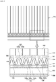
- FIG. 4 is a cross-sectional view showing a phase change of the refrigerant occurring in the refrigerant channel.
- the battery cooling device may be configured to cool the battery module 110 having a plurality of battery cells 112, and a refrigerant plate 120 may be used to restore the refrigerant evaporated by heat produced in the battery cells disposed at an upper flow side of the flow direction of the refrigerant, relative to the flow direction, to the liquid refrigerant, and the refrigerant plate 120 may be configured to perform the continuous phase change of the refrigerant in a flow direction of the refrigerant.
- the battery cooling device may include the refrigerant plate 120 in which the refrigerant flows for cooling the battery module 110, and a coolant plate 130 in which a coolant flows for cooling the refrigerant.
- the battery module 110 may include the plurality of battery cells 112 electrically connected in series, and cell covers 114 that support the plurality of battery cells 112. Each of the battery cells 112 as a least unit for generating electricity may be structurally divided by the cell covers 114 from each other. Furthermore, the plurality of battery cells 112 may be held in compartments provided in the cell covers 114 respectively, and may be arranged and supported in a line while held within the compartment. As shown in the drawings, the battery module 110 may be held in a battery case that surrounds the battery module 110, and may be submerged in an electrolyte in the battery case.
- the refrigerant plate 120 may be disposed on one side of the battery module 110 to enable heat exchange with the plurality of battery cells 112. Particularly, when the battery module 110 is loaded in a vehicle, the battery module 110 may be arranged in such a manner that the refrigerant plate is in contact with a lower end of the battery module 110. In particular, the refrigerant plate 120 may be disposed between the battery module 110 and the battery case, and may be disposed at lower ends of the plurality of battery cells 112, with the cell covers 114 between the refrigerant plate and the battery module (see FIG. 3 ). Heat produced in the battery cells 112 may be transferred via the cell covers 114 to the refrigerant plate 120.
- the cell covers 114 may be made of a material which allows the heat produced in the battery cells 112 to be efficiently transferred to the refrigerant plate 120.
- the refrigerant plate 120 may be disposed to extend in the arranged directions of the plurality of battery cells 112, and may include the refrigerant channel 122 which enables the refrigerant to flow in the arranged directions of the battery cells 112. As shown in FIGS. 1 to 3 , the refrigerant plate 120 may include a first plate member 124 and a second plate member 127, and the refrigerant channel 122 disposed between the first plate member 124 and the second plate member 127.
- the refrigerant flowing in the refrigerant channel 122 may be heated by heat produced in the plurality of battery cells 112, and may be cooled by the coolant flowing in the coolant plate 130.
- the refrigerant plate 120 may be arranged to neighbor (e.g., be proximate to) the plurality of battery cells 112 to enable heat transfer with the plurality of battery cells 112, and may be disposed to extend in the arranged directions of the battery cells 112.
- the refrigerant plate 120 may be disposed to neighbor (e.g., be proximate to) the coolant plate 130 to enable heat transfer with the coolant plate 130 for cooling the refrigerant.
- the refrigerant plate 120 may be disposed to neighbor (e.g., be proximate to) the battery cells 112 and the coolant plate 130, thereby performing heat exchange with the battery cells 112 and the coolant plate 130 due to contact therewith.
- the refrigerant plate 120 may be disposed between the plurality of battery cells 112 and the coolant plate 130 to perform heat exchange therewith, and the refrigerant of the refrigerant plate may be heated by heat released from the battery cells 112, and cooled by heat released from the coolant plate 130.
- the refrigerant flowing in the refrigerant channel 122 of the refrigerant plate 120 is heated by heat produced in the battery cells 112, the refrigerant may be evaporated, and when the refrigerant is cooled by heat (a chill) produced in the coolant plate 130, the refrigerant may be liquefied.
- the refrigerant channel 122 may include a corrugated structure repeating alternate ridges and grooves at an upper and a lower side thereof for generating repeated evaporation and liquefaction of the refrigerant.
- the refrigerant channel 122 may include a plurality of refrigerant heating channels 122a in which the refrigerant may be heated and evaporated by heat exchange with the battery cells 112, and a plurality of refrigerant cooling channels 122b in which the refrigerant may be cooled and liquefied by heat exchange with the coolant plate 130.
- the refrigerant heating channels 122a may be in contact with (e.g., abut) the battery cells 112 between the battery cells 112 and the coolant plate 130, and the refrigerant passing through the refrigerant heating channels 122a may be heated and evaporated by heat transferred from the battery cells 112 (see FIG. 4 ). Evaporation heat (e.g., the latent heat of vaporization) produced during the evaporation of the refrigerant may be used to cool the battery cells 112.
- Evaporation heat e.g., the latent heat of vaporization
- the refrigerant cooling channels 122b may be in contact with the coolant plate 130 between the battery cells 112 and the coolant plate 130, and the refrigerant passing through the refrigerant cooling channels 122b may be cooled and liquefied by heat transferred from the coolant plate 130 (see FIG. 4 ).
- each of the refrigerant heating channels 122a and each of the refrigerant cooling channels 122b may be alternately arranged in the arranged directions of the battery cells 112.
- Each of refrigerant transfer channels 122c may integrally extend from the refrigerant heating channel 122a to the refrigerant cooling channel 122b therebetween, and the refrigerant transfer channels 122c may be slantingly arranged at a predetermined angle (e.g., disposed at an incline) to achieve the flow efficiency of the refrigerant.
- FIG. 4 shows a state of the refrigerant being evaporated while the refrigerant receiving heat of the battery cells 112 transferred from the refrigerant heating channel 122a flows to a refrigerant transfer channel 122c-2, and a state of the refrigerant being liquefied while the refrigerant receiving heat of the coolant transferred from the refrigerant cooling channel 122b flows to a refrigerant transfer channel 122c-1.
- the liquid refrigerant may be evaporated by heat transferred from the battery cells 112.
- the refrigerant heated in the refrigerant heating channel 122a constantly flows to the refrigerant transfer channel 122c, the refrigerant may be evaporated and generate evaporation heat even while the refrigerant is flowing from the refrigerant heating channel 122a to the refrigerant transfer channel 122c.
- the evaporated refrigerant may be liquefied by heat transferred from the coolant plate 130.
- the refrigerant cooled in the refrigerant cooling channel 122b may constantly flow into the refrigerant transfer channel 122c disposed at a lower flow side of the refrigerant cooling channel 122b relative to the flow direction of the refrigerant. Accordingly, even when the refrigerant flows from the refrigerant cooling channel 122b to the refrigerant transfer channel 122c, the refrigerant may be condensed and restored to the liquid refrigerant.
- the refrigerant When the refrigerant passes through the refrigerant channel 122, the refrigerant may be evaporated by heat transferred from the battery cells 112, and then may be liquefied by heat transferred from the coolant plate 130, and such a phase change of the refrigerant may be repeated while the refrigerant flows in the refrigerant channel 122.
- the refrigerant may cool all of the battery cells 112 neighboring the refrigerant channel 122, and the evaporation heat (the latent heat of vaporization) produced when the refrigerant is evaporated by heat produced in the battery cells 112 is used to cool the battery cells 112 efficiently.
- the refrigerant plate 120 may cool all of the battery cells 112 of the battery module 110 by using the latent heat of vaporization, not by using the single-phase sensible heat, thereby increasing the cooling effect on each of the battery cells 112, and enabling the even cooling of all of the battery cells 112.
- FIG. 4 shows one example of a state change of the refrigerant. While maintaining a state changed in the refrigerant heating channel 122a (or the refrigerant cooling channel) at the upper flow side of the flow direction of the refrigerant, the refrigerant passing through the refrigerant transfer channel 122c may flow to the refrigerant cooling channel 122b (or the refrigerant heating channel) at the lower flow side of the flow direction of the refrigerant, whereby the phase of the refrigerant may turn into liquid or gas.
- first plate member 124 and the second plate member 127 of the refrigerant plate 120 may be disposed to oppose each other, with the refrigerant channel 122 disposed therebetween.
- the first plate member 124 and the second plate member 127 may be combined with and be fixed to each other while the first plate member 124 and the second plate member 127 are spaced apart from each other in parallel at an interval that corresponds to a height between an upper end of the refrigerant channel 122 and a lower end of the refrigerant channel 122.
- Combination of the first plate member 124 and the second plate member 127 may be performed at a position at which the refrigerant channel 122 is not interfered with the plate members.
- the first plate member 124 and the second plate member 127 may be disposed between the plurality of battery cells 112 and the coolant plate 130.
- the first plate member 124 may be arranged to enable heat exchange with the plurality of battery cells 112 due to contact therewith, and the second plate member 127 may be arranged to enable heat exchange with the coolant plate 130 due to contact therewith.
- the first plate member 124 may be arranged to be in contact with (e.g., abut) the lower ends (e.g., surfaces facing the coolant plate) of the plurality of battery cells 112 arranged in a line
- the second plate member 127 may be arranged to be in contact with an upper end (e.g., a surface facing the plurality of battery cells) of the coolant plate 130.
- a surface of the first plate member 124 in contact with the surfaces of the plurality of battery cells 112 may be configured as a surface (e.g., a flat surface) that corresponds to or marches the surfaces (exactly, surfaces of the cell covers holding the plurality of battery cells) of the plurality of battery cells 112, and a surface of the second plate member 127 in contact with a surface of the coolant plate 130 may be configured as a surface that corresponds to or marches the surface of the coolant plate 130.
- the first plate member 124 having surface in contact with the plurality of battery cells 112 may be formed as a flat surface and may be a flat plate
- the second plate member 127 with a surface in contact with the coolant plate 130 may be formed as a flat surface and may be a flat plate.
- the refrigerant channel 122 may be configured to have the corrugated structure which allows the refrigerant to flow in the arranged directions of the battery cells 112.
- the first plate member 124 and the second plate member 127 may have a first corrugated part 125 and a second corrugated part 128 thereon respectively to include the refrigerant channel 122 having the corrugated structure.
- the first plate member 124 may include the first corrugated part 125 on a surface thereof (e.g., a surface facing the coolant plate) which is not in contact with the battery cells 112 (e.g., spaced apart from the cells), and the second plate member 127 may include the second corrugated part 128 on a surface thereof (e.g., a surface facing the battery cells) which is not in contact with the coolant plate 130 (e.g., spaced apart from the coolant plate).
- Each of the first corrugated part 125 and the second corrugated part 128 may be formed to be a plate type having a cross-section of the corrugated structure, and may be joined and fixed by welding to the first plate member 124 and the second plate member 127 respectively.
- the first plate member 124 and the second plate member 127 may be combined with each other, with an interval between the first corrugated part 125 and the second corrugated part 128 maintained at a predetermined interval, and a space corresponding to the interval may be the refrigerant channel 122.
- the interval may be constantly maintained in an extending direction of the refrigerant channel 122.
- the first corrugated part 125 may have an area 125a (hereinbelow, referred to as 'a first joined area') joined to the surface of the first plate member 124 while being in surface contact with the surface of the first plate member 124, and an area 125b (hereinbelow, referred to as 'a first disjoined area') not being joined to the surface of the first plate member 124 and the two areas may be arranged alternately.
- 'a first joined area' joined to the surface of the first plate member 124 while being in surface contact with the surface of the first plate member 124
- an area 125b hereinbelow, referred to as 'a first disjoined area'
- the second corrugated part 128 may have an area 128a (hereinbelow, referred to as 'a second joined area') joined to the surface of the second plate member 127 while being in surface contact with the surface of the second plate member 127, and an area 128b (hereinbelow, referred to as 'a second disjoined area') not being joined to the surface of the second plate member 127 and the two areas may be arranged alternately.
- 'a second joined area' an area 128a (hereinbelow, referred to as 'a second joined area') joined to the surface of the second plate member 127 while being in surface contact with the surface of the second plate member 127
- an area 128b hereinbelow, referred to as 'a second disjoined area'
- the first corrugated part 125 and the second corrugated part 128 may be arranged such that the first joined area 125a faces the second disjoined area 128b, and the second joined area 128a faces the first disjoined area 125b.
- a space between the first joined area 125a and the second disjoined area may be the refrigerant heating channel 122a
- a space between the second joined area 128a and the first disjoined area 125b may be the refrigerant cooling channel 122b
- a space between the first disjoined area 125b and the second disjoined area 128b may be the refrigerant transfer channel 122c.
- Empty spaces in which the refrigerant does not flow may be provided between the first disjoined area 125b and the first plate member 124, and between the second disjoined area 128b and the second plate member 127.
- At least one first fin 126 may be disposed on a surface of the first corrugated part 125 corresponding to the first joined area 125a by protruding from the surface of the first corrugated part, and at least one second fin 129 may be disposed on a surface of the second corrugated part 128 corresponding to the second joined area 128a by protruding from the surface of the second corrugated part.
- the first fin 126 may be joined by welding to a surface of the first joined area 125a, and the first fin 126 may be joined by welding to a surface of the second joined area 128a.
- the first fin 126 may extend toward the refrigerant heating channel 122a, and the second fin 129 may extend toward the refrigerant cooling channel 122b.
- the first fin 126 and the second fin 129 may be fixed by furnace brazing, resistance welding, ultrasonic welding, and laser welding, etc. to the surfaces of the first corrugated part 125 and the second corrugated part 128 respectively.
- the first fin 126 and the second fin 129 increase contact surfaces between the refrigerant plate 120 and the refrigerant, thereby increasing a heat exchange amount of the refrigerant.
- the refrigerant plate 120 may include the first corrugated part 125 and the second corrugated part 128 having the refrigerant channel 122 defined by surrounding the refrigerant channel 122 and the first corrugated part 125 and the second corrugated part 128 may be joined to and supported by the first plate member 124 and the second plate member 127 respectively, thereby increasing rigidity of the refrigerant plate 120 and the heat exchange efficiency of the refrigerant.
- the refrigerant plate when the first plate member 124 and the second plate member 127 are not used, the refrigerant plate is in contact with the battery cells 112 and the coolant plate 130 only on the first joined area 125a of the first corrugated part 125 and the second joined area 128a of the second corrugated part 128, and the refrigerant plate is not in contact with the battery cells 112 and the coolant plate 130 on the first disjoined area 125b of the first corrugated part 125 and the second disjoined area 128b of the second corrugated part 128, and thus the heat exchange efficiency achieved by the refrigerant plate being in contact therewith decreases.
- the first plate member 124 and the second plate member 127 are provided to form the refrigerant plate 120, the first plate member 124 and the second plate member 127 are in contact with the battery cells 112 and the coolant plate 130 respectively without disjoined areas, and thus heat exchange efficiency achieved by the refrigerant plate 120 being in contact therewith increases.
- first corrugated part 125 and the second corrugated part 128 may be bent in structure. Accordingly, defining the refrigerant channel 122 between the first corrugated part 125 and the second corrugated part 128 by combining the first plate member 124 with the second plate member 127 in such a manner that the first corrugated part 125 and the second corrugated part 128 are joined to the first plate member 124 and the second plate member 127 respectively is easier in manufacturing process than defining the refrigerant channel 122 by combining the first corrugated part 125 with the second corrugated part 128 directly.
- the coolant plate 130 may be disposed at one side of the refrigerant plate 120 to enable heat exchange of the coolant plate with the refrigerant plate 120 due to contact therewith, and may be disposed at a side opposing the battery module 110, with the refrigerant plate 120 between the battery module and the coolant plate.
- the coolant plate 130 may include the coolant channel 132 in which the coolant flows, and the coolant may liquefy the refrigerant evaporated by heat produced in the battery cells 112. At least one coolant channel 132 may be provided in the coolant plate 130.
- the coolant plate 130 includes a plurality of coolant channels, the plurality of coolant channels 132 may be disposed in directions orthogonal to the arranged directions of the battery cells 112.
- each of the plurality of coolant channels 132 may extend in the arranged directions of the battery cells 112, and the flow direction of the coolant flowing in the coolant channels 132 may be the same as the flow direction of the refrigerant flowing in the refrigerant channel 122.
- the plurality of coolant channels 132 provided in the coolant plate 130 may be disposed in the same directions as the arranged directions of the battery cells 112.
- the coolant may turn a gas-phase refrigerant into a liquid-phase refrigerant to enable the continuous phase change of the refrigerant in the refrigerant channel 122, and the refrigerant may be selected and used in consideration of an operation temperature range of the battery cells 112.
- the refrigerant plate 120 may include interface members 141, 142 disposed on opposite sides thereof to improve a heat exchange performance of the refrigerant.
- a first interface member 141 may be disposed between the refrigerant plate 120 and the battery cells 112
- a second interface member 142 may be disposed between the refrigerant plate 120 and the coolant plate 130.
- the first interface member 141 and the second interface member 142 which are made of a thermal interface material (TIM), may be configured as flat plates such that the first interface member is in close contact with the cell covers 114 and the refrigerant plate 120 therebetween, and the second interface member is in close contact with the refrigerant plate 120 and the coolant plate 130 therebetween.
- TIM thermal interface material
- the TIM is a material which fills the gap or air-filled pore space between the cell covers 114 and the refrigerant plate 120 and between the refrigerant plate 120 and the coolant plate 130.
- the TIM is a material capable of improving heat exchange performance of the refrigerant when the first interface member 141 and the second interface member 142 are used, compared to when the first interface member 141 and the second interface member 142 are not used.
- FIG. 5 is a block diagram showing a circulation method of the refrigerant and the coolant provided into a battery system.
- the battery system B in which the refrigerant plate and the coolant plate are provided for cooling the battery module, may include a refrigerant pump P1 for circulating the refrigerant, and a coolant pump P2 for circulating the coolant to maintain temperature of the coolant at a predetermined range (e.g., a temperature range capable of restoring the evaporated refrigerant to the liquid refrigerant) for cooling the refrigerant, whereby the coolant discharged from the coolant plate may be cooled by a battery chiller C and/or a radiator R.
- a predetermined range e.g., a temperature range capable of restoring the evaporated refrigerant to the liquid refrigerant
Landscapes
- Engineering & Computer Science (AREA)
- Chemical & Material Sciences (AREA)
- Chemical Kinetics & Catalysis (AREA)
- Electrochemistry (AREA)
- General Chemical & Material Sciences (AREA)
- Manufacturing & Machinery (AREA)
- Mechanical Engineering (AREA)
- Life Sciences & Earth Sciences (AREA)
- Sustainable Development (AREA)
- Physics & Mathematics (AREA)
- Thermal Sciences (AREA)
- General Engineering & Computer Science (AREA)
- Sustainable Energy (AREA)
- Power Engineering (AREA)
- Transportation (AREA)
- Secondary Cells (AREA)
- Battery Mounting, Suspending (AREA)
Applications Claiming Priority (1)
| Application Number | Priority Date | Filing Date | Title |
|---|---|---|---|
| KR1020180065219A KR20190138919A (ko) | 2018-06-07 | 2018-06-07 | 차량용 배터리 냉각 장치 |
Publications (1)
| Publication Number | Publication Date |
|---|---|
| EP3579330A1 true EP3579330A1 (fr) | 2019-12-11 |
Family
ID=64048792
Family Applications (1)
| Application Number | Title | Priority Date | Filing Date |
|---|---|---|---|
| EP18203431.4A Pending EP3579330A1 (fr) | 2018-06-07 | 2018-10-30 | Dispositif de refroidissement de batterie pour véhicule |
Country Status (4)
| Country | Link |
|---|---|
| US (1) | US11038233B2 (fr) |
| EP (1) | EP3579330A1 (fr) |
| KR (1) | KR20190138919A (fr) |
| CN (1) | CN110581326B (fr) |
Cited By (4)
| Publication number | Priority date | Publication date | Assignee | Title |
|---|---|---|---|---|
| WO2020249906A1 (fr) * | 2019-06-11 | 2020-12-17 | Hutchinson | Ensemble a boitier thermiquement controle, pour cellules electriques |
| FR3111690A1 (fr) * | 2020-06-23 | 2021-12-24 | Hutchinson | Dispositif thermique à alimentation controlee en fluide fusible |
| WO2022053280A1 (fr) * | 2020-09-11 | 2022-03-17 | Daimler Ag | Agencement de refroidissement et agencement de batterie ayant une feuille de conduction thermique à plis multiples |
| DE102021115810A1 (de) | 2021-06-18 | 2022-12-22 | Audi Aktiengesellschaft | Kühleinrichtung für eine Batterie, Batterie, Kraftfahrzeug und Verfahren zum Herstellen einer Kühleinrichtung |
Families Citing this family (8)
| Publication number | Priority date | Publication date | Assignee | Title |
|---|---|---|---|---|
| US11254236B2 (en) * | 2019-10-25 | 2022-02-22 | Hanon Systems | High performance uniform temperature cold plate |
| JP7478922B2 (ja) * | 2020-09-28 | 2024-05-08 | パナソニックオートモーティブシステムズ株式会社 | 車両、及び、電池パック |
| CN113113696A (zh) * | 2021-04-12 | 2021-07-13 | 上海工程技术大学 | 一种电池热管理系统 |
| CN113540618B (zh) * | 2021-07-16 | 2022-07-22 | 重庆电子工程职业学院 | 一种工况稳定的电动汽车配电系统 |
| DE102021209304A1 (de) * | 2021-08-25 | 2023-03-02 | Robert Bosch Gesellschaft mit beschränkter Haftung | Kühlvorrichtung zur Kühlung eines Batteriezellstapels und Batteriesystem |
| FR3129717B1 (fr) * | 2021-11-29 | 2024-03-15 | Valeo Systemes Thermiques | Echangeur de chaleur pour vehicule electrique ou hybride |
| KR20230126173A (ko) * | 2022-02-21 | 2023-08-29 | 컨템포러리 엠퍼렉스 테크놀로지 씨오., 리미티드 | 배터리, 전기 장치, 배터리 제조 방법 및 장치 |
| WO2023239064A1 (fr) * | 2022-06-10 | 2023-12-14 | 삼성전자주식회사 | Structure de cadre et dispositif électronique la comprenant |
Citations (4)
| Publication number | Priority date | Publication date | Assignee | Title |
|---|---|---|---|---|
| US20100307723A1 (en) * | 2007-11-13 | 2010-12-09 | Behr Gmbh & Co. Kg | Device for cooling a heat source of a motor vehicle |
| US20110262794A1 (en) * | 2010-04-21 | 2011-10-27 | Jihyoung Yoon | Battery pack and cooling system for a battery pack |
| US20140138075A1 (en) * | 2012-11-19 | 2014-05-22 | Industrial Technology Research Institute | Heat exchanger and semiconductor module |
| US20150194714A1 (en) * | 2012-07-19 | 2015-07-09 | Sk Innovation Co., Ltd. | Battery module assembly |
Family Cites Families (3)
| Publication number | Priority date | Publication date | Assignee | Title |
|---|---|---|---|---|
| KR101021114B1 (ko) | 2008-11-14 | 2011-03-14 | 현대자동차일본기술연구소 | 차량 구동용 배터리 냉각장치 |
| KR20180062501A (ko) * | 2016-11-30 | 2018-06-11 | 현대자동차주식회사 | 배터리 수냉각 시스템 |
| KR102394801B1 (ko) * | 2017-10-20 | 2022-05-04 | 현대자동차주식회사 | 차량용 배터리 냉각 장치 |
-
2018
- 2018-06-07 KR KR1020180065219A patent/KR20190138919A/ko active IP Right Grant
- 2018-10-26 US US16/172,666 patent/US11038233B2/en active Active
- 2018-10-30 EP EP18203431.4A patent/EP3579330A1/fr active Pending
- 2018-11-20 CN CN201811382358.XA patent/CN110581326B/zh active Active
Patent Citations (4)
| Publication number | Priority date | Publication date | Assignee | Title |
|---|---|---|---|---|
| US20100307723A1 (en) * | 2007-11-13 | 2010-12-09 | Behr Gmbh & Co. Kg | Device for cooling a heat source of a motor vehicle |
| US20110262794A1 (en) * | 2010-04-21 | 2011-10-27 | Jihyoung Yoon | Battery pack and cooling system for a battery pack |
| US20150194714A1 (en) * | 2012-07-19 | 2015-07-09 | Sk Innovation Co., Ltd. | Battery module assembly |
| US20140138075A1 (en) * | 2012-11-19 | 2014-05-22 | Industrial Technology Research Institute | Heat exchanger and semiconductor module |
Cited By (5)
| Publication number | Priority date | Publication date | Assignee | Title |
|---|---|---|---|---|
| WO2020249906A1 (fr) * | 2019-06-11 | 2020-12-17 | Hutchinson | Ensemble a boitier thermiquement controle, pour cellules electriques |
| FR3111690A1 (fr) * | 2020-06-23 | 2021-12-24 | Hutchinson | Dispositif thermique à alimentation controlee en fluide fusible |
| WO2021260324A1 (fr) * | 2020-06-23 | 2021-12-30 | Hutchinson | Dispositif thermique a alimentation controlee en fluide fusible |
| WO2022053280A1 (fr) * | 2020-09-11 | 2022-03-17 | Daimler Ag | Agencement de refroidissement et agencement de batterie ayant une feuille de conduction thermique à plis multiples |
| DE102021115810A1 (de) | 2021-06-18 | 2022-12-22 | Audi Aktiengesellschaft | Kühleinrichtung für eine Batterie, Batterie, Kraftfahrzeug und Verfahren zum Herstellen einer Kühleinrichtung |
Also Published As
| Publication number | Publication date |
|---|---|
| US11038233B2 (en) | 2021-06-15 |
| US20190379014A1 (en) | 2019-12-12 |
| CN110581326B (zh) | 2023-07-14 |
| KR20190138919A (ko) | 2019-12-17 |
| CN110581326A (zh) | 2019-12-17 |
Similar Documents
| Publication | Publication Date | Title |
|---|---|---|
| US11038233B2 (en) | Battery cooling device for vehicle | |
| CN109698394B (zh) | 用于车辆的电池冷却装置 | |
| JP7122664B2 (ja) | 車両、熱交換プレート、及び電池パック | |
| JP6601573B2 (ja) | 蒸発器 | |
| EP2659543B1 (fr) | Module de batterie, système de gestion de température de batterie et véhicule équipé de celui-ci | |
| JP6756278B2 (ja) | バッテリ冷却システム | |
| JP6693480B2 (ja) | 端子冷却装置 | |
| EP2068390A1 (fr) | Système de batterie avec des cellules de batterie agencées dans un alignement de réseau | |
| KR20210157429A (ko) | 고성능 균일 온도 냉각판 | |
| JP2012190674A (ja) | バッテリー装置 | |
| JP2012190675A (ja) | バッテリー装置 | |
| JP2011183862A (ja) | 車両走行用バッテリーの温度調整装置 | |
| US20190372185A1 (en) | Cooling structure for vehicle battery | |
| JP5450043B2 (ja) | バッテリー温調システム用の熱交換器とその製造方法 | |
| WO2020203152A1 (fr) | Dispositif de refroidissement de type à thermosiphon pour véhicule | |
| WO2020213535A1 (fr) | Dispositif de refroidissement du type à thermosiphon pour véhicules | |
| WO2019123881A1 (fr) | Appareil de réglage de température de dispositif | |
| JP2019113301A (ja) | 機器温調装置 | |
| JP7300633B2 (ja) | 車両、熱交換プレート、及び電池パック | |
| CN113764770B (zh) | 冷却器 | |
| CN216436002U (zh) | 用于电气部件的热调节装置和热调节壳体 | |
| WO2019146262A1 (fr) | Dispositif de refroidissement de thermosiphon pour véhicule | |
| JP2020136040A (ja) | 温度調整装置 | |
| CN118235008A (zh) | 机动车辆的电气和/或电子元件的热交换器 |
Legal Events
| Date | Code | Title | Description |
|---|---|---|---|
| PUAI | Public reference made under article 153(3) epc to a published international application that has entered the european phase |
Free format text: ORIGINAL CODE: 0009012 |
|
| STAA | Information on the status of an ep patent application or granted ep patent |
Free format text: STATUS: THE APPLICATION HAS BEEN PUBLISHED |
|
| AK | Designated contracting states |
Kind code of ref document: A1 Designated state(s): AL AT BE BG CH CY CZ DE DK EE ES FI FR GB GR HR HU IE IS IT LI LT LU LV MC MK MT NL NO PL PT RO RS SE SI SK SM TR |
|
| AX | Request for extension of the european patent |
Extension state: BA ME |
|
| STAA | Information on the status of an ep patent application or granted ep patent |
Free format text: STATUS: REQUEST FOR EXAMINATION WAS MADE |
|
| 17P | Request for examination filed |
Effective date: 20200610 |
|
| RBV | Designated contracting states (corrected) |
Designated state(s): AL AT BE BG CH CY CZ DE DK EE ES FI FR GB GR HR HU IE IS IT LI LT LU LV MC MK MT NL NO PL PT RO RS SE SI SK SM TR |
|
| RAP3 | Party data changed (applicant data changed or rights of an application transferred) |
Owner name: HYUNDAI MOTOR COMPANY Owner name: KIA CORPORATION |
|
| STAA | Information on the status of an ep patent application or granted ep patent |
Free format text: STATUS: EXAMINATION IS IN PROGRESS |
|
| 17Q | First examination report despatched |
Effective date: 20221019 |
|
| P01 | Opt-out of the competence of the unified patent court (upc) registered |
Effective date: 20230511 |