EP3578747B1 - Fenêtre de toît à ventilation améliorée - Google Patents
Fenêtre de toît à ventilation améliorée Download PDFInfo
- Publication number
- EP3578747B1 EP3578747B1 EP19178718.3A EP19178718A EP3578747B1 EP 3578747 B1 EP3578747 B1 EP 3578747B1 EP 19178718 A EP19178718 A EP 19178718A EP 3578747 B1 EP3578747 B1 EP 3578747B1
- Authority
- EP
- European Patent Office
- Prior art keywords
- sash
- ventilation device
- unit
- top member
- roof window
- Prior art date
- Legal status (The legal status is an assumption and is not a legal conclusion. Google has not performed a legal analysis and makes no representation as to the accuracy of the status listed.)
- Active
Links
Images


Classifications
-
- E—FIXED CONSTRUCTIONS
- E06—DOORS, WINDOWS, SHUTTERS, OR ROLLER BLINDS IN GENERAL; LADDERS
- E06B—FIXED OR MOVABLE CLOSURES FOR OPENINGS IN BUILDINGS, VEHICLES, FENCES OR LIKE ENCLOSURES IN GENERAL, e.g. DOORS, WINDOWS, BLINDS, GATES
- E06B7/00—Special arrangements or measures in connection with doors or windows
- E06B7/02—Special arrangements or measures in connection with doors or windows for providing ventilation, e.g. through double windows; Arrangement of ventilation roses
- E06B7/10—Special arrangements or measures in connection with doors or windows for providing ventilation, e.g. through double windows; Arrangement of ventilation roses by special construction of the frame members
-
- E—FIXED CONSTRUCTIONS
- E04—BUILDING
- E04D—ROOF COVERINGS; SKY-LIGHTS; GUTTERS; ROOF-WORKING TOOLS
- E04D13/00—Special arrangements or devices in connection with roof coverings; Protection against birds; Roof drainage ; Sky-lights
- E04D13/03—Sky-lights; Domes; Ventilating sky-lights
- E04D13/035—Sky-lights; Domes; Ventilating sky-lights characterised by having movable parts
-
- F—MECHANICAL ENGINEERING; LIGHTING; HEATING; WEAPONS; BLASTING
- F24—HEATING; RANGES; VENTILATING
- F24F—AIR-CONDITIONING; AIR-HUMIDIFICATION; VENTILATION; USE OF AIR CURRENTS FOR SCREENING
- F24F13/00—Details common to, or for air-conditioning, air-humidification, ventilation or use of air currents for screening
- F24F13/08—Air-flow control members, e.g. louvres, grilles, flaps or guide plates
- F24F13/18—Air-flow control members, e.g. louvres, grilles, flaps or guide plates specially adapted for insertion in flat panels, e.g. in door or window-pane
Definitions
- the present invention relates to a roof window comprising a frame having a plurality of frame members including a top member, two side members and a bottom member, a sash having a plurality of sash members including a top member, two side members and a bottom member, of which at least the sash top member includes a separate sash top unit forming part of or constituting the sash top member, and at least one ventilation device including a plurality of ventilation openings to provide ventilation between an exterior side and an interior side of the window.
- Such windows come in a number of varieties and models.
- the windows are generally equipped with operating means as well as ventilation means.
- Some roof windows are provided with a ventilation flap rotatably connected to the sash, which at the same time fulfils the role of operating means to release and activate a lock cooperating with the frame.
- FR 2 899 930 A1 discloses an air inlet system comprising a front grille and a rear mounting frame mounted in a recess of a sash.
- the ventilation device By forming the ventilation device in the sash top unit and at the same time allowing the ventilation device to be releasably inserted into and removed from the sash top unit, a number of advantages are obtained. Based on the recognition that the need for maintenance or even replacement of components of the ventilation device surpasses the maintenance interval of other parts of the roof window, it is now easy and flexible to simply remove the ventilation device from the top sash unit, and then either re-introduce the same ventilation device, or a new one, when needed.
- the releasable engagement by non-positive engagement only renders the use of structure penetrating fastening means such as screws redundant. This is particularly an advantage in those circumstances that the top sash unit is made of a plastic material.
- the ventilation device has a longitudinal configuration extending between a first end and a second end, a length dimension being defined between the first and second ends substantially in parallel with a length direction of the sash top member, a height dimension perpendicular to the length dimension substantially in parallel with a width direction of the sash top member, and a thickness dimension perpendicular to the length dimension substantially in parallel with a thickness direction of the sash top member.
- the engagement means are positioned at one or both of said first and second end and comprise at least one biasing device connected to the ventilation device and contacting the top sash unit of the sash top member in frictional engagement. This provides for excellent retention of the ventilation device in the top sash unit, while at the same time making retraction of the ventilation device easy and logical.
- the top sash unit is provided with a track to accommodate the ventilation device, and the top sash unit is provided with a plurality of ventilation openings to match the ventilation openings of the ventilation device. This improves the ventilation conditions even further.
- the top sash unit forms part of the sash top member and has a longitudinal extension defining a length exceeding the length of the at least one ventilation device, and the top sash unit is connected to the remaining parts of the sash top member at a respective longitudinal end.
- the top sash unit is accommodated in a recessed portion of the sash top member and is held by its longitudinal ends to a respective end portion of the sash top member, the end portions of the sash top member being optionally formed by extended portions of the sash side members, by means of a flange portion of the top sash unit contacting an abutment portion associated to a transition portion.
- This provides for a reliable and inconspicuous connection.
- the top sash unit is fastened to the remaining parts of the sash top member by means of fastening means, such as screws, introduced through a plurality of apertures.
- the sash top member is provided with an additional set of ventilation openings, preferably in the form of a first plurality of vent slits facing the top sash unit and a second plurality of vent slits in connection with the first plurality of vent slits and facing the interior side of the window.
- an additional set of ventilation openings preferably in the form of a first plurality of vent slits facing the top sash unit and a second plurality of vent slits in connection with the first plurality of vent slits and facing the interior side of the window.
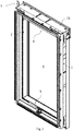
- FIG. 1 the general configuration of a roof window is shown.
- the roof window here comprises a primary frame in the form of a stationary frame 1 configured for installation in an inclined roof surface, here by means of mounting brackets 3 provided at the corners, but other installation principles may be applied as well.
- the frame 1 comprises a plurality of frame members, here including a frame top member 11, two frame side members 12 and 13, and a frame bottom member 14.
- At least one secondary frame is connected to the stationary frame 1, in the embodiment shown a sash 2 carrying a pane 4.
- the sash 2 is pivotally connected to the stationary frame 2 in order to be able to rotate the sash 2 to an open position.
- the sash 2 is provided hinge fitting part (not shown), cooperating with a counterpart hinge fitting part (not shown) provided on the frame 1.
- the sash 2 comprises, corresponding to the frame 1, a sash top member 21, two sash side members 22 and 23, and a sash bottom member 24.
- the hinge axis could be located arbitrarily in the roof window, but is here substantially centre-hinged.
- the roof window could be top-hinged as well, meaning that the hinge axis is located near the frame top member 11 and the sash top member 21.
- the user operates the operating device of the window, here in the form of a handle 5 at the bottom member 24 of the sash 2. Further details of the handle 5 are the subject of Applicant's copending patent application having the same filing date as the present application, and the contents thereof are incorporated herein by reference.
- the roof window is provided with a ventilation device 6 accommodated in a top sash unit 7, acting to allow passage of air also in the closed position of the window.
- the top sash unit 7 has a length dimension, a width dimension and a thickness dimension configured to cover a substantial part of the sash top member 21.
- roof windows come in different sizes, it is understood that the person skilled in the art will be able to select such suitable length and width dimensions without undue burden.
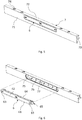
- the roof window is shown to comprise frame 1 with top member, two side members and a bottom member 11, 12, 13, 14, and sash 2 with top member, two side members and a bottom member 21, 22, 23, 24.
- At least the sash top member 21 includes a separate sash top unit 7 forming part of or constituting the sash top member 21.
- Other sash members may in principle be provided with separate sash units as well to form part of or constitute the sash member in question. The principles of such a separate unit could in principle be transferred to the frame as well, and also applies to fixed, i.e. not openable windows.
- More than one ventilation device 6 may be provided in one sash or frame member. In the following, only one ventilation device 6 accommodated in the top sash unit 7 forming part of the sash top member 21 will be referred to.
- the ventilation device 6 includes a plurality of ventilation openings 67 to provide ventilation between an exterior side and an interior side of the window.
- the ventilation openings 67 are formed between bars 66 spaced apart by a certain distance.
- the ventilation device 6 has a longitudinal configuration extending between a first end 6a and a second end 6b, a length dimension being defined between the first and second ends 6a, 6b substantially in parallel with a length direction of the sash top member 21, a height dimension perpendicular to the length dimension substantially in parallel with a width direction of the sash top member, and a thickness dimension perpendicular to the length dimension substantially in parallel with a thickness direction of the sash top member.
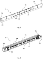
- the ventilation device 6 functions as a well-known so-called click valve, in which a cover section 62 surrounded by border section 61 includes two push buttons 63 which may be activated independently of each other such that if one is activated, the cover section 62 will assume an inclined position and allowing air to flow in and out via a wedge-shaped opening, and if both push buttons 63 are activated, the cover section 62 will assume a position substantially in parallel with the border section 61.
- the operating principles resemble those of a pen, i.e. reactivation of the lock is achieved by pushing the push buttons 63 back. Such principles are well-known and will not be described in further detail, although snap lock 60 responding to the activating push-buttons 63 is shown in Fig. 9 .
- a back section 64 is provided adjacent but retracted from the border section 61.
- engagement means generally designated 65 are provided at the back section 64.
- the engagement means 65 are non-positive, i.e. force dependent only, and do not require removal of an obstacle in order to be released.
- the engagement means 65 serve to releasably connect the ventilation device 6 to the sash top unit 7.
- the engagement means 65 are positioned at both of the first and second end 6a, 6b and comprise at least one biasing device connected to the ventilation device 6 and contacting the top sash unit 7 of the sash top member 21 in frictional engagement, as will be described in further detail below.
- the top sash unit 7 is provided with a track 75.
- the top sash unit 7 is provided with a plurality of ventilation openings 77 to match the ventilation openings 67 of the ventilation device 6, also separated by bars 76.
- top sash unit 7 forms part of the sash top member 21 and has a longitudinal extension defining a length exceeding the length of the ventilation device 6.
- the top sash unit 7 is connected to the remaining parts of the sash top member 21 at a respective longitudinal end 7a, 7b.
- the top sash unit 7 has a front face 71 to which the border section 61 of the ventilation device 6 is substantially flush.
- a top face 72 adjoins the front face 71.
- a ledge 78 is provided at a distance in the height direction from the top face 72. Bars 76 thus extend between the ledge 78 and the underside of the top face 72.
- the top sash unit 7 is accommodated in a recessed portion 211 of the sash top member 21 and is held by its longitudinal ends 7a, 7b to a respective end portion 210 of the sash top member 21, the end portions 210 of the sash top member 21 being here formed by extended portions of the sash side members 22, 23.
- a flange portion 73 at each end 7a, 7b of the top sash unit 7 contacts an abutment portion 212 associated to a transition portion 213.
- top sash unit 7 is fastened to the remaining parts of the sash top member 21 by means of fastening means, such as screws, introduced through a plurality of apertures 74.
- the top sash unit 7 may for instance be provided as a moulded element and may be used both with a sash of wood and of a plastic material such as polyurethane (PU).
- PU polyurethane
- the top sash unit 7 is a plastic injection moulded element, with a surface adapted to be painted with a lacquer in order to resemble the surface finish of PU
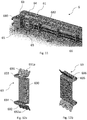
- FIGs 9 to 11 and Figs 12a and 12b another embodiment will be described with particular focus on the biasing device of the engagement means of the ventilation device 6.
- elements having the same or analogous function carry the same reference numerals.
- the biasing means comprises a spring lever 69 having at least one engagement portion 691, 692 to contact a corresponding flange portion 791, 792 on the top sash unit 7 in frictional engagement. Furthermore, at least one fastening portion 693, 694 is provided for fastening the spring lever 69 to the remaining parts of the ventilation device 6.
- the spring lever 69 is formed as a substantially plate-shaped element comprising a number of bent portions with a length direction substantially parallel with the height dimension of the ventilation device 6, said bent portions including said at least one fastening portion 691, 692.
- a first and a second engagement portion 691, 692 are provided as each an inclined plate section at opposite ends of a substantially plane bridge portion 690. In this way, the first and second engagement portions 691, 692 are allowed to flex resiliently when contacting the top sash unit 7.
- a first and second fastening portions 693, 694 are provided as respective folded sections between a respective engagement portion 691, 692 and said bridge portion 690.
- Each engagement portion 691, 692 is provided with friction-increasing means, preferably in the form of a set of teeth 691a, 692a.
- opening 696 in plane section 695 of each fastening portion 693, 694 In addition to being an advantage during manufacture, this also assists in the resilient flexing of the engagement portions 691, 692.
- the back side of the ventilation device 6 comprises an end block 680 at each longitudinal end 6a, 6b, between which a first and a second ledge 681, 682 extend. It is apparent that the bars 66 separating the ventilation openings 67 extend in the height direction between the first and second ledges 681, 682.
- Simple fastening of the spring lever 6 to the remaining parts of the ventilation device 6 is here obtained in that the respective folded sections forming the first and second fastening portions 693, 694 of the ventilation device are clamped on to the respective first and second ledge 681, 682 of the ventilation device 6.
- the parts of the ventilation device 6 are typically made of moulded plastic parts.
- the biasing means here the spring lever 69, may be made of metal, for instance spring steel.
- the sash top member 21 is provided with an additional set of ventilation openings, preferably in the form of a first plurality of vent slits, here in the form of recess vent slits 214, facing the top sash unit 7 and a second plurality of vent slits, here in the form of inner vent slits 215, in connection with the recess vent slits 214 and facing the interior side of the window.
- the sash 2 is also provided with a lock bolt 216 interacting with an aperture (not shown) in the frame, for holding the sash 2 parked in a ventilation or cleaning position.
Landscapes
- Engineering & Computer Science (AREA)
- Civil Engineering (AREA)
- Structural Engineering (AREA)
- Chemical & Material Sciences (AREA)
- Combustion & Propulsion (AREA)
- Mechanical Engineering (AREA)
- General Engineering & Computer Science (AREA)
- Architecture (AREA)
- Specific Sealing Or Ventilating Devices For Doors And Windows (AREA)
Claims (11)
- Fenêtre de toit comprenant
un cadre (1) ayant une pluralité d'organes de cadre comportant un organe supérieur, deux organes latéraux et un organe inférieur (11, 12, 13, 14),
un châssis (2) ayant une pluralité d'organes de châssis comportant un organe supérieur, deux organes latéraux et un organe inférieur (21, 22, 23, 24), dont au moins l'organe de châssis supérieur (21) comporte une unité de châssis supérieure (7) faisant partie de l'organe de châssis supérieur (21) ou constituant celui-ci, et
au moins un dispositif de ventilation (6) comportant une pluralité d'ouvertures de ventilation (67) pour assurer la ventilation entre un côté extérieur et un côté intérieur de la fenêtre,
ledit au moins un dispositif de ventilation (6) étant reçu dans l'unité de châssis supérieure (7),
ledit au moins un dispositif de ventilation (6) étant connecté de manière amovible à l'unité de châssis supérieure (7) par le biais d'un moyen d'engagement non positif (65),
l'au moins un dispositif de ventilation (6) ayant une configuration longitudinale s'étendant entre une première extrémité (6a) et une deuxième extrémité (6b), une dimension en longueur étant définie entre les première et deuxième extrémités (6a, 6b) sensiblement parallèlement à une direction en longueur de l'organe de châssis supérieur (21), une dimension en hauteur perpendiculaire à la dimension en longueur sensiblement parallèlement à une direction en largeur de l'organe de châssis supérieur, et une dimension d'épaisseur perpendiculaire à la dimension en longueur sensiblement parallèlement à une direction d'épaisseur de l'organe de châssis supérieur, ledit moyen d'engagement non positif (65) étant positionné à une desdites première et deuxième extrémités (6a, 6b)ou aux deux et comprenant au moins un dispositif de sollicitation connecté au dispositif de ventilation (6) et venant en contact avec l'unité de châssis supérieure (7) de l'organe de châssis supérieur (21) avec engagement par friction et
l'unité de châssis supérieure (7) étant pourvue d'une glissière (75) pour recevoir le dispositif de ventilation (6), et l'unité de châssis supérieure (7) étant pourvue d'une pluralité d'ouvertures de ventilation (77) prévues pour coïncider avec les ouvertures de ventilation (67) du dispositif de ventilation (6),
caractérisée en ce que
l'au moins un dispositif de sollicitation du moyen d'engagement non positif (65) de l'au moins un dispositif de ventilation (6) comprend un levier à ressort (69) ayant au moins une portion d'engagement (691, 692) prévue pour venir en contact avec une portion de bride correspondante (791, 792) sur l'unité de châssis supérieure (7) avec engagement par friction, et au moins une portion d'attache (693, 694) pour attacher le levier à ressort (69) aux parties restantes de l'au moins un dispositif de ventilation (6). - Fenêtre de toit selon la revendication 1, dans laquelle l'unité de châssis supérieure (7) fait partie de l'organe de châssis supérieur (21) et présente une extension longitudinale définissant une longueur dépassant la longueur de l'au moins un dispositif de ventilation (6), et dans laquelle l'unité de châssis supérieure (7) est connectée aux parties restantes de l'organe de châssis supérieur (21) au niveau d'une extrémité longitudinale respective (7a, 7b).
- Fenêtre de toit selon la revendication 2, dans laquelle l'unité de châssis supérieure (7) est reçue dans une portion en retrait (211) de l'organe de châssis supérieur (21) et est retenue par ses extrémités longitudinales (7a, 7b) au niveau d'une portion d'extrémité respective (210) de l'organe de châssis supérieur (21), les portions d'extrémité (210) de l'organe de châssis supérieur (21) étant facultativement formées par des portions prolongées des organes de châssis latéraux (22, 23), au moyen d'une portion de bride (73) de l'unité de châssis supérieure (7) venant en contact avec une portion de butée (212) associée à une portion de transition (213).
- Fenêtre de toit selon la revendication 3, dans laquelle l'unité de châssis supérieure (7) est attachée aux parties restantes de l'organe de châssis supérieur (21) au moyen de moyens d'attache tels que des vis, introduits à travers une pluralité d'ouvertures (74).
- Fenêtre de toit selon l'une quelconque des revendications précédentes, dans laquelle l'organe de châssis supérieur (21) est pourvu d'un jeu supplémentaire d'ouvertures de ventilation, de préférence sous la forme d'une première pluralité de fentes de ventilation (214) faisant face à l'unité de châssis supérieure (7) et une deuxième pluralité de fentes de ventilation (215) en liaison avec la première pluralité de fentes de ventilation (214) et faisant face au côté intérieur de la fenêtre.
- Fenêtre de toit selon l'une quelconque des revendications précédentes, dans laquelle le levier à ressort (69) est formé sous forme d'élément substantiellement en forme de plaque, comprenant un certain nombre de portions recourbées avec une direction en longueur sensiblement parallèle à la dimension en hauteur du dispositif de ventilation (6), lesdites portions recourbées comportant ladite au moins une portion d'attache (691, 692).
- Fenêtre de toit selon la revendication 6, dans laquelle une première et une deuxième portion d'engagement (691, 692) sont prévues chacune sous la forme d'une section de plaque inclinée à des extrémités opposées d'une portion de pont sensiblement plane (690) .
- Fenêtre de toit selon la revendication 7, dans laquelle une première et une deuxième portion d'attache (693, 694) sont prévues au niveau de sections pliées respectives entre une portion d'engagement respective (691, 692) et ladite portion de pont (690).
- Fenêtre de toit selon la revendication 8, dans laquelle chaque portion d'engagement (691, 692) est pourvue de moyens pour augmenter la friction, de préférence sous la forme d'un jeu de dents (691a, 692a) .
- Fenêtre de toit selon l'une quelconque des revendications précédentes, dans laquelle le dispositif de ventilation (6) comprend une section de bordure (61), une section de recouvrement (62) avec au moins un moyen d'activation, de préférence sous la forme d'au moins un bouton poussoir (63), et une section arrière (64) reçue dans la glissière (75) dans l'unité de châssis supérieure (7), associée au moyen d'engagement (65) .
- Fenêtre de toit selon l'une quelconque des revendications 8 à 10, dans laquelle les sections pliées respectives formant la première et la deuxième portion d'attache (693, 694) du dispositif de ventilation sont serrées sur un premier et un deuxième rebord respectif (681, 682) du dispositif de ventilation (6).
Priority Applications (1)
| Application Number | Priority Date | Filing Date | Title |
|---|---|---|---|
| PL19178718T PL3578747T3 (pl) | 2018-06-06 | 2019-06-06 | Okno dachowe z ulepszoną wentylacją |
Applications Claiming Priority (1)
| Application Number | Priority Date | Filing Date | Title |
|---|---|---|---|
| DKPA201870326A DK180433B1 (en) | 2018-06-06 | 2018-06-06 | Roof window with ventilation |
Publications (2)
| Publication Number | Publication Date |
|---|---|
| EP3578747A1 EP3578747A1 (fr) | 2019-12-11 |
| EP3578747B1 true EP3578747B1 (fr) | 2020-11-18 |
Family
ID=66776202
Family Applications (1)
| Application Number | Title | Priority Date | Filing Date |
|---|---|---|---|
| EP19178718.3A Active EP3578747B1 (fr) | 2018-06-06 | 2019-06-06 | Fenêtre de toît à ventilation améliorée |
Country Status (4)
| Country | Link |
|---|---|
| EP (1) | EP3578747B1 (fr) |
| CN (1) | CN211473932U (fr) |
| DK (1) | DK180433B1 (fr) |
| PL (1) | PL3578747T3 (fr) |
Family Cites Families (5)
| Publication number | Priority date | Publication date | Assignee | Title |
|---|---|---|---|---|
| GB0302805D0 (en) * | 2003-02-07 | 2003-03-12 | Harding Jane C M | Window vent |
| FR2899930B1 (fr) * | 2006-04-18 | 2008-06-27 | Ind De Moules Et Moulages Plas | Systeme d'entree d'air et montant equipe d'un tel systeme |
| DK176947B1 (da) * | 2007-12-03 | 2010-06-21 | Form & Plast As | Friskluftventil |
| PL2751355T5 (pl) | 2011-10-04 | 2019-04-30 | Vkr Holding As | Okno dachowe z górnym modułem skrzydła okiennego |
| EP2757222B1 (fr) * | 2013-01-18 | 2018-05-30 | VKR Holding A/S | Clapet d'appel d'air frais avec mécanisme de verrouillage pour plaque de couverture |
-
2018
- 2018-06-06 DK DKPA201870326A patent/DK180433B1/en not_active IP Right Cessation
-
2019
- 2019-06-04 CN CN201920837634.0U patent/CN211473932U/zh active Active
- 2019-06-06 PL PL19178718T patent/PL3578747T3/pl unknown
- 2019-06-06 EP EP19178718.3A patent/EP3578747B1/fr active Active
Non-Patent Citations (1)
| Title |
|---|
| None * |
Also Published As
| Publication number | Publication date |
|---|---|
| DK180433B1 (en) | 2021-04-23 |
| EP3578747A1 (fr) | 2019-12-11 |
| PL3578747T3 (pl) | 2021-06-14 |
| CN211473932U (zh) | 2020-09-11 |
| DK201870326A1 (en) | 2020-01-14 |
Similar Documents
| Publication | Publication Date | Title |
|---|---|---|
| US6988759B2 (en) | Multi-configuration vehicle door system | |
| EP0269701B2 (fr) | Charniere pour meuble | |
| US8096593B2 (en) | Latch for sliding door or frame | |
| KR20010042829A (ko) | 슬라이드 래치 | |
| US6176040B1 (en) | Slotted lever device for keeping an automotive door in an open position | |
| EP3578747B1 (fr) | Fenêtre de toît à ventilation améliorée | |
| EP1069273B1 (fr) | Porte pour toilette | |
| GB2112059A (en) | Latch mechanism for hinged panels | |
| US5803526A (en) | Ergonomic automotive compartment access system | |
| MXPA01001951A (es) | Montaje guia para ventana de guillotina con inclinacion hacia fuera. | |
| EP2011936B1 (fr) | Poignée détachable pour portes ou fenêtres | |
| JP3898006B2 (ja) | キャビネット | |
| KR100279572B1 (ko) | 자동차의 도어핸들 그립구조 | |
| DE102018007867A1 (de) | Griffeinheit für eine Tür oder Klappe eines Kraftfahrzeugs | |
| JP3405272B2 (ja) | スライドドアの支持構造 | |
| US4862641A (en) | Door latch and stop mechanism | |
| GB1589512A (en) | Drawers | |
| JP5118955B2 (ja) | 建具や家具の取付け台座 | |
| US20190119919A1 (en) | Gutter assembly utilizing a latch actuated bottom debris release door | |
| USRE33554E (en) | Toilets | |
| KR200150745Y1 (ko) | 버스 선반의 도어잠금장치 | |
| DE19608402A1 (de) | Schloßinnenbetätigung an einer Fahrzeugtür | |
| JP3302584B2 (ja) | 上げ落し金具の落し棒ガイドおよびこれを備えた扉体 | |
| KR20030097214A (ko) | 도어체커 기능을 갖는 도어힌지장치 | |
| EP1186734A1 (fr) | Système d'actionnement pour une porte de véhicule |
Legal Events
| Date | Code | Title | Description |
|---|---|---|---|
| PUAI | Public reference made under article 153(3) epc to a published international application that has entered the european phase |
Free format text: ORIGINAL CODE: 0009012 |
|
| STAA | Information on the status of an ep patent application or granted ep patent |
Free format text: STATUS: THE APPLICATION HAS BEEN PUBLISHED |
|
| AK | Designated contracting states |
Kind code of ref document: A1 Designated state(s): AL AT BE BG CH CY CZ DE DK EE ES FI FR GB GR HR HU IE IS IT LI LT LU LV MC MK MT NL NO PL PT RO RS SE SI SK SM TR |
|
| AX | Request for extension of the european patent |
Extension state: BA ME |
|
| STAA | Information on the status of an ep patent application or granted ep patent |
Free format text: STATUS: REQUEST FOR EXAMINATION WAS MADE |
|
| 17P | Request for examination filed |
Effective date: 20200227 |
|
| RBV | Designated contracting states (corrected) |
Designated state(s): AL AT BE BG CH CY CZ DE DK EE ES FI FR GB GR HR HU IE IS IT LI LT LU LV MC MK MT NL NO PL PT RO RS SE SI SK SM TR |
|
| GRAP | Despatch of communication of intention to grant a patent |
Free format text: ORIGINAL CODE: EPIDOSNIGR1 |
|
| STAA | Information on the status of an ep patent application or granted ep patent |
Free format text: STATUS: GRANT OF PATENT IS INTENDED |
|
| INTG | Intention to grant announced |
Effective date: 20200710 |
|
| GRAS | Grant fee paid |
Free format text: ORIGINAL CODE: EPIDOSNIGR3 |
|
| GRAA | (expected) grant |
Free format text: ORIGINAL CODE: 0009210 |
|
| STAA | Information on the status of an ep patent application or granted ep patent |
Free format text: STATUS: THE PATENT HAS BEEN GRANTED |
|
| AK | Designated contracting states |
Kind code of ref document: B1 Designated state(s): AL AT BE BG CH CY CZ DE DK EE ES FI FR GB GR HR HU IE IS IT LI LT LU LV MC MK MT NL NO PL PT RO RS SE SI SK SM TR |
|
| REG | Reference to a national code |
Ref country code: GB Ref legal event code: FG4D |
|
| REG | Reference to a national code |
Ref country code: CH Ref legal event code: EP |
|
| REG | Reference to a national code |
Ref country code: IE Ref legal event code: FG4D |
|
| REG | Reference to a national code |
Ref country code: DE Ref legal event code: R096 Ref document number: 602019001358 Country of ref document: DE |
|
| REG | Reference to a national code |
Ref country code: AT Ref legal event code: REF Ref document number: 1335974 Country of ref document: AT Kind code of ref document: T Effective date: 20201215 |
|
| REG | Reference to a national code |
Ref country code: NL Ref legal event code: FP |
|
| PG25 | Lapsed in a contracting state [announced via postgrant information from national office to epo] |
Ref country code: RS Free format text: LAPSE BECAUSE OF FAILURE TO SUBMIT A TRANSLATION OF THE DESCRIPTION OR TO PAY THE FEE WITHIN THE PRESCRIBED TIME-LIMIT Effective date: 20201118 Ref country code: PT Free format text: LAPSE BECAUSE OF FAILURE TO SUBMIT A TRANSLATION OF THE DESCRIPTION OR TO PAY THE FEE WITHIN THE PRESCRIBED TIME-LIMIT Effective date: 20210318 Ref country code: FI Free format text: LAPSE BECAUSE OF FAILURE TO SUBMIT A TRANSLATION OF THE DESCRIPTION OR TO PAY THE FEE WITHIN THE PRESCRIBED TIME-LIMIT Effective date: 20201118 Ref country code: GR Free format text: LAPSE BECAUSE OF FAILURE TO SUBMIT A TRANSLATION OF THE DESCRIPTION OR TO PAY THE FEE WITHIN THE PRESCRIBED TIME-LIMIT Effective date: 20210219 Ref country code: NO Free format text: LAPSE BECAUSE OF FAILURE TO SUBMIT A TRANSLATION OF THE DESCRIPTION OR TO PAY THE FEE WITHIN THE PRESCRIBED TIME-LIMIT Effective date: 20210218 |
|
| PG25 | Lapsed in a contracting state [announced via postgrant information from national office to epo] |
Ref country code: BG Free format text: LAPSE BECAUSE OF FAILURE TO SUBMIT A TRANSLATION OF THE DESCRIPTION OR TO PAY THE FEE WITHIN THE PRESCRIBED TIME-LIMIT Effective date: 20210218 Ref country code: IS Free format text: LAPSE BECAUSE OF FAILURE TO SUBMIT A TRANSLATION OF THE DESCRIPTION OR TO PAY THE FEE WITHIN THE PRESCRIBED TIME-LIMIT Effective date: 20210318 Ref country code: LV Free format text: LAPSE BECAUSE OF FAILURE TO SUBMIT A TRANSLATION OF THE DESCRIPTION OR TO PAY THE FEE WITHIN THE PRESCRIBED TIME-LIMIT Effective date: 20201118 Ref country code: SE Free format text: LAPSE BECAUSE OF FAILURE TO SUBMIT A TRANSLATION OF THE DESCRIPTION OR TO PAY THE FEE WITHIN THE PRESCRIBED TIME-LIMIT Effective date: 20201118 |
|
| REG | Reference to a national code |
Ref country code: LT Ref legal event code: MG9D |
|
| PG25 | Lapsed in a contracting state [announced via postgrant information from national office to epo] |
Ref country code: HR Free format text: LAPSE BECAUSE OF FAILURE TO SUBMIT A TRANSLATION OF THE DESCRIPTION OR TO PAY THE FEE WITHIN THE PRESCRIBED TIME-LIMIT Effective date: 20201118 |
|
| PG25 | Lapsed in a contracting state [announced via postgrant information from national office to epo] |
Ref country code: EE Free format text: LAPSE BECAUSE OF FAILURE TO SUBMIT A TRANSLATION OF THE DESCRIPTION OR TO PAY THE FEE WITHIN THE PRESCRIBED TIME-LIMIT Effective date: 20201118 Ref country code: SM Free format text: LAPSE BECAUSE OF FAILURE TO SUBMIT A TRANSLATION OF THE DESCRIPTION OR TO PAY THE FEE WITHIN THE PRESCRIBED TIME-LIMIT Effective date: 20201118 Ref country code: SK Free format text: LAPSE BECAUSE OF FAILURE TO SUBMIT A TRANSLATION OF THE DESCRIPTION OR TO PAY THE FEE WITHIN THE PRESCRIBED TIME-LIMIT Effective date: 20201118 Ref country code: LT Free format text: LAPSE BECAUSE OF FAILURE TO SUBMIT A TRANSLATION OF THE DESCRIPTION OR TO PAY THE FEE WITHIN THE PRESCRIBED TIME-LIMIT Effective date: 20201118 Ref country code: RO Free format text: LAPSE BECAUSE OF FAILURE TO SUBMIT A TRANSLATION OF THE DESCRIPTION OR TO PAY THE FEE WITHIN THE PRESCRIBED TIME-LIMIT Effective date: 20201118 |
|
| REG | Reference to a national code |
Ref country code: DE Ref legal event code: R097 Ref document number: 602019001358 Country of ref document: DE |
|
| PG25 | Lapsed in a contracting state [announced via postgrant information from national office to epo] |
Ref country code: DK Free format text: LAPSE BECAUSE OF FAILURE TO SUBMIT A TRANSLATION OF THE DESCRIPTION OR TO PAY THE FEE WITHIN THE PRESCRIBED TIME-LIMIT Effective date: 20201118 |
|
| PLBE | No opposition filed within time limit |
Free format text: ORIGINAL CODE: 0009261 |
|
| STAA | Information on the status of an ep patent application or granted ep patent |
Free format text: STATUS: NO OPPOSITION FILED WITHIN TIME LIMIT |
|
| 26N | No opposition filed |
Effective date: 20210819 |
|
| PG25 | Lapsed in a contracting state [announced via postgrant information from national office to epo] |
Ref country code: AL Free format text: LAPSE BECAUSE OF FAILURE TO SUBMIT A TRANSLATION OF THE DESCRIPTION OR TO PAY THE FEE WITHIN THE PRESCRIBED TIME-LIMIT Effective date: 20201118 Ref country code: IT Free format text: LAPSE BECAUSE OF FAILURE TO SUBMIT A TRANSLATION OF THE DESCRIPTION OR TO PAY THE FEE WITHIN THE PRESCRIBED TIME-LIMIT Effective date: 20201118 |
|
| PG25 | Lapsed in a contracting state [announced via postgrant information from national office to epo] |
Ref country code: SI Free format text: LAPSE BECAUSE OF FAILURE TO SUBMIT A TRANSLATION OF THE DESCRIPTION OR TO PAY THE FEE WITHIN THE PRESCRIBED TIME-LIMIT Effective date: 20201118 |
|
| PG25 | Lapsed in a contracting state [announced via postgrant information from national office to epo] |
Ref country code: ES Free format text: LAPSE BECAUSE OF FAILURE TO SUBMIT A TRANSLATION OF THE DESCRIPTION OR TO PAY THE FEE WITHIN THE PRESCRIBED TIME-LIMIT Effective date: 20201118 Ref country code: MC Free format text: LAPSE BECAUSE OF FAILURE TO SUBMIT A TRANSLATION OF THE DESCRIPTION OR TO PAY THE FEE WITHIN THE PRESCRIBED TIME-LIMIT Effective date: 20201118 |
|
| PG25 | Lapsed in a contracting state [announced via postgrant information from national office to epo] |
Ref country code: LU Free format text: LAPSE BECAUSE OF NON-PAYMENT OF DUE FEES Effective date: 20210606 |
|
| PG25 | Lapsed in a contracting state [announced via postgrant information from national office to epo] |
Ref country code: IE Free format text: LAPSE BECAUSE OF NON-PAYMENT OF DUE FEES Effective date: 20210606 |
|
| PG25 | Lapsed in a contracting state [announced via postgrant information from national office to epo] |
Ref country code: IS Free format text: LAPSE BECAUSE OF FAILURE TO SUBMIT A TRANSLATION OF THE DESCRIPTION OR TO PAY THE FEE WITHIN THE PRESCRIBED TIME-LIMIT Effective date: 20210318 |
|
| REG | Reference to a national code |
Ref country code: AT Ref legal event code: UEP Ref document number: 1335974 Country of ref document: AT Kind code of ref document: T Effective date: 20201118 |
|
| REG | Reference to a national code |
Ref country code: CH Ref legal event code: PL |
|
| PG25 | Lapsed in a contracting state [announced via postgrant information from national office to epo] |
Ref country code: LI Free format text: LAPSE BECAUSE OF NON-PAYMENT OF DUE FEES Effective date: 20220630 Ref country code: CH Free format text: LAPSE BECAUSE OF NON-PAYMENT OF DUE FEES Effective date: 20220630 |
|
| PG25 | Lapsed in a contracting state [announced via postgrant information from national office to epo] |
Ref country code: CY Free format text: LAPSE BECAUSE OF FAILURE TO SUBMIT A TRANSLATION OF THE DESCRIPTION OR TO PAY THE FEE WITHIN THE PRESCRIBED TIME-LIMIT Effective date: 20201118 |
|
| PG25 | Lapsed in a contracting state [announced via postgrant information from national office to epo] |
Ref country code: HU Free format text: LAPSE BECAUSE OF FAILURE TO SUBMIT A TRANSLATION OF THE DESCRIPTION OR TO PAY THE FEE WITHIN THE PRESCRIBED TIME-LIMIT; INVALID AB INITIO Effective date: 20190606 |
|
| PG25 | Lapsed in a contracting state [announced via postgrant information from national office to epo] |
Ref country code: MK Free format text: LAPSE BECAUSE OF FAILURE TO SUBMIT A TRANSLATION OF THE DESCRIPTION OR TO PAY THE FEE WITHIN THE PRESCRIBED TIME-LIMIT Effective date: 20201118 |
|
| PG25 | Lapsed in a contracting state [announced via postgrant information from national office to epo] |
Ref country code: TR Free format text: LAPSE BECAUSE OF FAILURE TO SUBMIT A TRANSLATION OF THE DESCRIPTION OR TO PAY THE FEE WITHIN THE PRESCRIBED TIME-LIMIT Effective date: 20201118 |
|
| PG25 | Lapsed in a contracting state [announced via postgrant information from national office to epo] |
Ref country code: MT Free format text: LAPSE BECAUSE OF FAILURE TO SUBMIT A TRANSLATION OF THE DESCRIPTION OR TO PAY THE FEE WITHIN THE PRESCRIBED TIME-LIMIT Effective date: 20201118 |
|
| PGFP | Annual fee paid to national office [announced via postgrant information from national office to epo] |
Ref country code: NL Payment date: 20250516 Year of fee payment: 7 |
|
| PGFP | Annual fee paid to national office [announced via postgrant information from national office to epo] |
Ref country code: DE Payment date: 20250507 Year of fee payment: 7 Ref country code: PL Payment date: 20250515 Year of fee payment: 7 |
|
| PGFP | Annual fee paid to national office [announced via postgrant information from national office to epo] |
Ref country code: GB Payment date: 20250501 Year of fee payment: 7 |
|
| PGFP | Annual fee paid to national office [announced via postgrant information from national office to epo] |
Ref country code: BE Payment date: 20250516 Year of fee payment: 7 |
|
| PGFP | Annual fee paid to national office [announced via postgrant information from national office to epo] |
Ref country code: FR Payment date: 20250523 Year of fee payment: 7 |
|
| PGFP | Annual fee paid to national office [announced via postgrant information from national office to epo] |
Ref country code: AT Payment date: 20250528 Year of fee payment: 7 |
|
| PGFP | Annual fee paid to national office [announced via postgrant information from national office to epo] |
Ref country code: CZ Payment date: 20250529 Year of fee payment: 7 |