EP3578741B1 - Felgenschloss - Google Patents
Felgenschloss Download PDFInfo
- Publication number
- EP3578741B1 EP3578741B1 EP19178075.8A EP19178075A EP3578741B1 EP 3578741 B1 EP3578741 B1 EP 3578741B1 EP 19178075 A EP19178075 A EP 19178075A EP 3578741 B1 EP3578741 B1 EP 3578741B1
- Authority
- EP
- European Patent Office
- Prior art keywords
- cog wheel
- bolt
- support plate
- casing
- lock
- Prior art date
- Legal status (The legal status is an assumption and is not a legal conclusion. Google has not performed a legal analysis and makes no representation as to the accuracy of the status listed.)
- Active
Links
Images


Classifications
-
- E—FIXED CONSTRUCTIONS
- E05—LOCKS; KEYS; WINDOW OR DOOR FITTINGS; SAFES
- E05C—BOLTS OR FASTENING DEVICES FOR WINGS, SPECIALLY FOR DOORS OR WINDOWS
- E05C9/00—Arrangements of simultaneously actuated bolts or other securing devices at well-separated positions on the same wing
- E05C9/04—Arrangements of simultaneously actuated bolts or other securing devices at well-separated positions on the same wing with two sliding bars moved in opposite directions when fastening or unfastening
- E05C9/047—Arrangements of simultaneously actuated bolts or other securing devices at well-separated positions on the same wing with two sliding bars moved in opposite directions when fastening or unfastening comprising key-operated locks, e.g. a lock cylinder to drive auxiliary deadbolts or latch bolts
-
- E—FIXED CONSTRUCTIONS
- E05—LOCKS; KEYS; WINDOW OR DOOR FITTINGS; SAFES
- E05B—LOCKS; ACCESSORIES THEREFOR; HANDCUFFS
- E05B17/00—Accessories in connection with locks
- E05B17/04—Devices for coupling the turning cylinder of a single or a double cylinder lock with the bolt operating member
- E05B17/042—Devices for coupling the turning cylinder of a single or a double cylinder lock with the bolt operating member using toothed wheels or geared sectors
-
- E—FIXED CONSTRUCTIONS
- E05—LOCKS; KEYS; WINDOW OR DOOR FITTINGS; SAFES
- E05B—LOCKS; ACCESSORIES THEREFOR; HANDCUFFS
- E05B59/00—Locks with latches separate from the lock-bolts or with a plurality of latches or lock-bolts
-
- E—FIXED CONSTRUCTIONS
- E05—LOCKS; KEYS; WINDOW OR DOOR FITTINGS; SAFES
- E05B—LOCKS; ACCESSORIES THEREFOR; HANDCUFFS
- E05B17/00—Accessories in connection with locks
- E05B17/20—Means independent of the locking mechanism for preventing unauthorised opening, e.g. for securing the bolt in the fastening position
- E05B17/2007—Securing, deadlocking or "dogging" the bolt in the fastening position
-
- E—FIXED CONSTRUCTIONS
- E05—LOCKS; KEYS; WINDOW OR DOOR FITTINGS; SAFES
- E05B—LOCKS; ACCESSORIES THEREFOR; HANDCUFFS
- E05B63/00—Locks or fastenings with special structural characteristics
- E05B63/0056—Locks with adjustable or exchangeable lock parts
-
- E—FIXED CONSTRUCTIONS
- E05—LOCKS; KEYS; WINDOW OR DOOR FITTINGS; SAFES
- E05B—LOCKS; ACCESSORIES THEREFOR; HANDCUFFS
- E05B9/00—Lock casings or latch-mechanism casings ; Fastening locks or fasteners or parts thereof to the wing
- E05B9/08—Fastening locks or fasteners or parts thereof, e.g. the casings of latch-bolt locks or cylinder locks to the wing
- E05B9/084—Fastening of lock cylinders, plugs or cores
-
- E—FIXED CONSTRUCTIONS
- E05—LOCKS; KEYS; WINDOW OR DOOR FITTINGS; SAFES
- E05C—BOLTS OR FASTENING DEVICES FOR WINGS, SPECIALLY FOR DOORS OR WINDOWS
- E05C9/00—Arrangements of simultaneously actuated bolts or other securing devices at well-separated positions on the same wing
- E05C9/04—Arrangements of simultaneously actuated bolts or other securing devices at well-separated positions on the same wing with two sliding bars moved in opposite directions when fastening or unfastening
- E05C9/045—Arrangements of simultaneously actuated bolts or other securing devices at well-separated positions on the same wing with two sliding bars moved in opposite directions when fastening or unfastening with inclined surfaces, e.g. spiral or helicoidal
Definitions
- the present invention relates to a rim lock that ensures high security and flexibility of use.
- a rim lock generally has a casing that houses a cylinder for actuating a bolt and a spring latch.
- rim locks are present on the market; they differ in the type of cylinder, for example the European cylinder, Swiss cylinder, pump cylinder, etc., and the mechanism inside the casing designed to actuate the bolt and the spring latch.
- WO 2009/087464 A1 discloses a mortise lock fitted with multiple locking bolts, the lock being actuated in different operable position;
- WO2015/000898 A1 discloses a lock cylinder of the type comprising a toothed wheel actuable by one key cylinder of the cylinder, where the toothed wheel is intended to drive one pin of a lock receiving the cylinder
- the technical task of the present invention is thus to provide a rim lock which enables the aforesaid technical drawbacks of the prior art to be eliminated.
- one object of the invention is to provide a high-security rim lock that uses components which are compatible for operation with cylinders of a varying type.
- a further object of the invention is to provide a rim lock which offers a high standard of security, irrespective of the type of cylinder used.
- Yet another object of the invention is to provide a high-security rim lock that has a simple and inexpensive construction.
- a rim lock comprising a casing which houses a bolt and a spring latch extractable through a flank of said casing, and a cylinder for actuating said bolt and said spring latch having a drive cog wheel, characterised in that said casing houses a first support plate of the bolt which is translatable in the extraction direction of the bolt, a second support plate of the spring latch which is translatable in the extraction direction of the spring latch parallel to said first plate, at least a first driven cog wheel connected to said drive cog wheel and having a rotation axis fixed to said casing, a drawing pin of said first plate supported by said first driven cog wheel, a return lever of the spring latch oscillating in opposition to and by action of an elastic element, a drawing member of said return lever supported by said first driven cog wheel, and in that, when said bolt is in a completely extracted position, said drawing pin and said rotation axis of said first driven wheel are aligned in the extraction direction
- a wall of said casing preferably has an end stop of said drawing pin, and when said bolt is in a completely extracted position, said drawing pin engages said end stop.
- said first driven cog wheel and a second driven cog wheel are provided, said first driven cog wheel is driven by said second drive cog wheel, which is in turn driven by said drive cog wheel.
- the second drive cog wheel if present, has the primary purpose of modifying the transmission ratio so as to reduce the actuating strain on the key.
- said first plate has a wall interfering with said second plate when said bolt is in a completely extracted position so as to lock said spring latch in a completely extracted position.
- a second drive cog wheel interposed between said drive cog wheel and said first driven cog wheel.
- said second drive cog wheel meshes directly with said drive cog wheel and has a pinion that meshes with said first driven cog wheel.
- said casing houses at least a relay member for a locking peg, said relay member being constrained to said bolt translatable perpendicularly to said bolt.
- the present invention further discloses a set of rim locks which differ in the type of cylinder used and have the same bolt, same spring latch, same first and second support plate, same wall of said casing, same first driven cog wheel and same transmission ratio between said drive cog wheel and said first driven cog wheel.
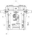
- the lock 1 comprises a casing 2, 3, 4, 5, 6, 7 which houses a bolt 8 translatable for extraction and retraction into the casing 2, 3, 4, 5, 6, 7, a spring latch 9 which is translatable parallel to the bolt 8 for extraction from and retraction into the casing 2, 3, 4, 5, 6, 7, and a cylinder 10 for actuating the bolt 8 and the spring latch 9.
- the casing 2, 3, 4, 5, 6, 7 has the shape of a parallelepiped and has a front wall 2, a rear wall 3, and two flanks 4, 5.
- the front wall 2 of the casing 2, 3, 4, 5, 6, 7 is formed by a flat front plate 11
- the rear wall 3 and the two flanks 4, 5 are formed by a "U"-shaped rear plate 12
- the upper side 6 and the lower side 7 of the casing 2, 3, 4, 5 are delimited by the upper and lower walls of a cover 13, which also covers the front wall 2 and the two flanks 4, 5, of the casing 2, 3, 4, 5, 6, 7.
- the flat front plate 11 is fixed by means of screws 14 to the "U"-shaped rear plate 12, whilst the cover 13 is fixed by means of screws 15 to the flanks 4, 5 of the "U"-shaped rear plate 12.
- the casing 2, 3, 4, 5, 6, 7 houses a first support plate 16 of the bolt 8 and a second support plate 17 of the spring latch 9.
- the first support plate 16 is supported by the casing 2, 3, 4, 5, 6, 7 translatably in the direction of extraction and retraction of the bolt 8 from the flank 4 of the casing 2, 3, 4, 5, 6, 7.
- the second support plate 17 is supported by the casing 2, 3, 4, 5, 6, 7 translatably in the direction of extraction and retraction of the spring latch 8 from the same flank 4 of the casing 2, 3, 4, 5, 6, 7.
- the first support plate 16 and the second support plate 17 lie mainly in parallel planes positioned adjacent to each other.
- first support plate 16 and the second support plate 17 lie mainly in planes parallel to the plane in which the flat front plate 11 delimiting the casing 2, 3, 4, 5, 6, 7 lies.
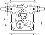
- the cylinder 10 has a drive cog wheel 18 connected to at least a first driven cog wheel 19.
- the drive cog wheel 18 has a rotation axis 20 perpendicular to the planes in which the first support plate 16 and the second support plate 17 mainly lie.
- the first driven cog wheel 19 has a rotation axis 21 parallel to the rotation axis of the drive cog wheel 18.
- the rotation axis 21 of the first driven cog wheel 19 is fixed between the front wall 2 and the rear wall 3 of the casing 2, 3, 4, 5, 6, 7.
- the second drive cog wheel 35 meshes directly with the drive cog wheel 18 and has a coaxial pinion 36 that meshes with the first driven cog wheel 19.
- the rotation axis 37 of the second drive cog wheel 35 is fixed to the casing 2, 3, 4, 5, 6, 7 parallel to the rotation axis 21 of the first driven cog wheel 19.
- the casing 2, 3, 4, 5, 6, 7 internally comprises an insert 38 fixed by means of screws 48 to the rear wall 3 of the casing 2, 3, 4, 5, 6, 7 and said insert 38 directly supports the cylinder 10 with the drive cog wheel 18 and the rotation axis 37 of the second drive cog wheel 35.
- the insert 38 has an engagement seat 60 for a screw 61 fastened against a pawl 62 projecting laterally from the cylinder 10 so as to lock the cylinder 10 in the lock.
- the first driven cog wheel 19 supports a drawing pin 22 for drawing the first support plate 16 of the bolt 8.
- the drawing pin 22 is fixed to the first driven cog wheel 19 in an eccentric position parallel to the rotation axis 21 of the first driven cog wheel 19 and engages slidingly in a slot 23 of the first support plate 16.
- the first driven cog wheel 19 further supports a drawing member 24 for drawing a return lever 25 of the spring latch 9.
- the drawing member 24 is fixed to the first driven cog wheel 19 in a peripheral position and engages with a tooth 27 for picking up the movement formed on a first arm of the return lever 25.
- the return lever 25 oscillates in opposition to and by the action of an elastic element 26.
- the rotation axis 28 of the return lever 25 is parallel to the axis 21 of the first driven cog wheel 19 and is fixed to the casing 2, 3, 4, 5, 6, 7.
- the second arm of the return lever 25 has a slot 29 in which a pin 30 fixed to the second support plate 17 is slidingly engaged so that the rotation of the return lever 25 may be transmitted to the spring latch 9.
- the elastic element 26 is in particular a torsion spring having one attached to the casing 2, 3, 4, 5, 6, 7 and one end attached to the return lever 25.
- the elastic element 26 retains the return lever 25 in a position associated with the complete extraction of the spring latch 9.
- the retraction of the spring latch 9 can be effected by overcoming the force of the elastic element 26 or manually by means of a grip 31 fixed to the second support plate 17 or by being driven by the cylinder 10.
- the drawing pin 22 is engaged in a slot 32 present on a wall of the casing 2, 3, 4, 5, 6, 7.
- the slot 32 defines, at one end thereof, an end stop for the drawing pin 22.
- the slot 32 is fashioned on the front wall 2 of the casing 2, 3, 4, 5, 6, 7.
- the slot 32 has the shape of an arch centred on the rotation axis 21 of the first driven cog wheel 19.
- the drawing pin 22 is engaged with the end stop and is aligned with the axis 21 of the first driven cog wheel 19 in the extraction direction of the bolt 8.
- the lock has an incremental break-in resistance, since in a break-in attempt, if a force is applied in the retraction direction of the bolt 8, part of this force is released by the drawing pin 22 onto the wall of the slot 32 and from the latter directly onto the axis 21 of the first driven cog wheel 19.
- the first support plate 16 has a wall 33 interfering with the second support plate 17 when the bolt 8 is in a completely extracted position so as to lock the spring latch 9 in a completely extracted position.
- the wall 33 is in particular a perimeter wall of the first support plate 16 proximal to the bolt 8 and interferes with a projection 34 of the second support plate 17.
- the projection 34 is perpendicular to the plane in which the second support plate 17 mainly lies and is set in a position proximal to the spring latch 9.
- the casing 2, 3, 4, 5, 6, 7 houses at least a relay member for a locking peg, in particular a first relay member 40 for a first locking peg and a second relay member 41 for a second locking peg.
- Each relay member 40, 41 is guided in translation perpendicular to the bolt 8.
- each relay member 40, 41 has an inclined slot 42, 43 in which a pin 44, 45 mounted in the first support plate 16 slidingly engages.
- the first plate 16, the second plate 17, and the wall 2 of the casing in which the slot 32 is provided have passage openings 46, 47 compatible for introducing and fixing various types of cylinder 10 to the casing 2, 3, 4, 5, 6, 7.
- the various locks thus differ in the type of cylinder used, but they have the same bolt 8, the same spring latch 9, the same first and second support plate 16, 17, a casing with the same wall 2 which includes the slot 32, the same first driven cog wheel 19 and the same transmission ratio between the drive cog wheel 19 and the first driven cog wheel 18.
- a part of the casing 2, 3, 4, 5, 6, 7, as well as the cylinder 10, can vary from one lock to another.
- the drive cog wheel 18 When the key is inserted and turned in the cylinder 10, the drive cog wheel 18 is set into rotation and thus actuates the gear which also comprises the first driven cog wheel 19 and the second driven cog wheel 35 with its pinion 36.
- the first driven cog wheel 19 moves the drawing pin 22, which moves the first support plate 16, which in turn moves the bolt 8 in the extraction direction and the relay members 40, 41 with the respective locking pegs.
- the materials used, as well as the dimensions, may in practice be of any type, according to needs and the state of the art.
Landscapes
- Engineering & Computer Science (AREA)
- Mechanical Engineering (AREA)
- Lock And Its Accessories (AREA)
- Pharmaceuticals Containing Other Organic And Inorganic Compounds (AREA)
Claims (11)
- Kastenschloss (1), umfassend ein Gehäuse (2, 3, 4, 5, 6, 7), das einen Bolzen (8) und einen Federriegel (9) beherbergt, der durch eine Flanke (4) des Gehäuses (2, 3, 4, 5, 6, 7) herausziehbar ist, und einen Betätigungszylinder (10) des Bolzens (8), und wobei der Federriegel (9) ein Antriebszahnrad (18) aufweist, wobei das Gehäuse (2, 3, 4, 5, 6, 7) eine erste Trägerplatte (16) des Bolzens (8), die in der Auszugsrichtung des Bolzens (8) übersetzbar ist, eine zweite Trägerplatte (17) des Federriegels (9), die in der Auszugsrichtung des Federriegels (9) parallel zu der ersten Platte (17) übersetzbar ist, mindestens ein erstes angetriebenes Zahnrad (19), das mit dem Antriebszahnrad (18) verbunden ist und eine Drehachse (21) aufweist, die an dem Gehäuse (2, 3, 4, 5, 6, 7) befestigt ist, einen Zugstift (22) der ersten Trägerplatte (16), der von dem ersten angetriebenen Zahnrad (19) getragen wird, wobei ein Rückstellhebel (25) des Federriegels (9) entgegengesetzt und durch Einwirkung eines elastischen Elements (26) einschwingt, ein Zugglied (24) des Rückstellhebels (25), der vom ersten angetriebenen Zahnrad (19) getragen wird, und wenn sich der Bolzen (8) in einer vollständig herausgezogenen Position befindet, beherbergt, wobei der Zugstift (22) und die Drehachse (21) des ersten angetriebenen Rades (19) in der Auszugsrichtung des Bolzens (8) ausgerichtet sind, dadurch gekennzeichnet, dass die erste Trägerplatte (16), die zweite Trägerplatte (17) und die Wand (2) des Gehäuses (2, 3, 4, 5, 6, 7) Durchgangsöffnungen (46, 47), die zur Montage verschiedener Zylindertypen (10) geeignet sind, aufweisen.
- Kastenschloss (1) nach Anspruch 1, dadurch gekennzeichnet, dass eine Wand (2) des Gehäuses (2, 3, 4, 5, 6, 7) einen Endanschlag des Zugstifts (22) aufweist, und dadurch, dass der Zugstift (22) in den Endanschlag eingreift, wenn sich der Bolzen (8) in einer vollständig herausgezogenen Position befindet.
- Kastenschloss (1) nach dem vorhergehenden Anspruch, dadurch gekennzeichnet, dass der Endanschlag durch das Ende eines Gleitschlitzes (32) des Zugstifts (22) gebildet wird.
- Kastenschloss (1) nach einem der vorhergehenden Ansprüche, dadurch gekennzeichnet, dass die erste Trägerplatte (16) eine Wand (33) aufweist, die mit der zweiten Trägerplatte (17) interferiert, wenn sich der Bolzen (8) in einer vollständig herausgezogenen Position befindet, um den Federriegel (9) in einer vollständig herausgezogenen Position zu verriegeln.
- Kastenschloss (1) nach einem der vorhergehenden Ansprüche, dadurch gekennzeichnet, dass die erste und die zweite Trägerplatte (16, 17) parallele Hauptliegeebenen aufweisen, die nebeneinander angeordnet sind.
- Kastenschloss (1) nach dem vorhergehenden Anspruch 4, dadurch gekennzeichnet, dass die Wand (33) mit der ersten Trägerplatte (16) durch einen Vorsprung (34) der zweiten Trägerplatte (17) interferiert, der senkrecht zu deren Liegeebene ist.
- Kastenschloss (1) nach einem der vorhergehenden Ansprüche, dadurch gekennzeichnet, dass es ein zweites angetriebenes Zahnrad (35) umfasst, das zwischen dem Antriebszahnrad (18) und dem ersten angetriebenen Zahnrad (19) angeordnet ist.
- Kastenschloss (1) nach dem vorhergehenden Anspruch, dadurch gekennzeichnet, dass das zweite angetriebene Zahnrad (35) direkt mit dem angetriebenen Zahnrad (18) kämmt und ein Ritzel (36) aufweist, das mit dem ersten angetriebenen Zahnrad (19) kämmt.
- Kastenschloss (1) nach einem der vorhergehenden Ansprüche, dadurch gekennzeichnet, dass das Gehäuse (2, 3, 4, 5, 6, 7) mindestens ein Relaisglied (40, 41) für einen Verriegelungszapfen beherbergt, wobei das Relaisglied (40, 41) auf dem Bolzen (8) festgespannt ist, der senkrecht zu dem Bolzen (8) übersetzbar ist.
- Kastenschloss (1) nach einem der vorhergehenden Ansprüche, dadurch gekennzeichnet, dass das Gehäuse (2, 3, 4, 5, 6, 7) innen einen Einsatz (38) mit einem Eingriffssitz (60) für eine Schraube (61) aufweist, die gegen eine Sperrklinke (62) befestigt ist, die seitlich aus dem Zylinder (10) herausragt, um den Zylinder (10) in dem Schloss zu verriegeln.
- Satz Kastenschlösser nach einem der vorhergehenden Ansprüche, der sich durch den verwendeten Zylindertyp (10) unterscheidet und den gleichen Bolzen (8), den gleichen Federriegel (9), die gleiche erste und zweite Trägerplatte (16, 17), die gleiche Wand (2) des Gehäuses (2, 3, 4, 5, 6, 7) aufweist, wobei er den Endanschlag, das erste angetriebene Zahnrad (19) und das Übersetzungsverhältnis zwischen dem Antriebsrad (18) und dem ersten angetriebenen Zahnrad (19) enthält.
Applications Claiming Priority (1)
| Application Number | Priority Date | Filing Date | Title |
|---|---|---|---|
| IT102018000006138A IT201800006138A1 (it) | 2018-06-08 | 2018-06-08 | Serratura da applicare |
Publications (2)
| Publication Number | Publication Date |
|---|---|
| EP3578741A1 EP3578741A1 (de) | 2019-12-11 |
| EP3578741B1 true EP3578741B1 (de) | 2021-05-19 |
Family
ID=63312425
Family Applications (1)
| Application Number | Title | Priority Date | Filing Date |
|---|---|---|---|
| EP19178075.8A Active EP3578741B1 (de) | 2018-06-08 | 2019-06-04 | Felgenschloss |
Country Status (2)
| Country | Link |
|---|---|
| EP (1) | EP3578741B1 (de) |
| IT (1) | IT201800006138A1 (de) |
Family Cites Families (5)
| Publication number | Priority date | Publication date | Assignee | Title |
|---|---|---|---|---|
| DE69203339D1 (de) * | 1992-04-14 | 1995-08-10 | Deny S A | Elektrisch oder mechanisch betätigbare Schlossvorrichtung mit schmalem Profil. |
| DE20115832U1 (de) * | 2001-09-26 | 2002-10-24 | Ernst Straub GmbH, 78464 Konstanz | Montageadapter zur adaptiven Anpassung von Einsteck-Schliessprofilzylindern |
| WO2009087464A1 (en) * | 2007-12-26 | 2009-07-16 | Goldtec Migun 2005 Ltd. | Mortise lock |
| WO2015000989A1 (fr) * | 2013-07-02 | 2015-01-08 | Tordjman | Cylindre de serrure, serrure équipée d'un tel cylindre |
| DE202017002691U1 (de) * | 2017-05-19 | 2017-06-21 | Kfv Karl Fliether Gmbh & Co. Kg | Zylinderbetätigtes Türschloss |
-
2018
- 2018-06-08 IT IT102018000006138A patent/IT201800006138A1/it unknown
-
2019
- 2019-06-04 EP EP19178075.8A patent/EP3578741B1/de active Active
Also Published As
| Publication number | Publication date |
|---|---|
| IT201800006138A1 (it) | 2019-12-08 |
| EP3578741A1 (de) | 2019-12-11 |
Similar Documents
| Publication | Publication Date | Title |
|---|---|---|
| US4154070A (en) | Locking arrangement for doors and the like | |
| DK2314808T3 (en) | Electromechanical cylinder for a lock | |
| US8677792B2 (en) | Electronic door lock apparatus | |
| NO313299B1 (no) | Returanordning for et manövreringsorgan for en lås, samt en beslaglås eller tilsvarende omfattende minst ±n mutter for enfangbolt | |
| US6212812B1 (en) | Pistol with trigger locking mechanism | |
| CN102782235B (zh) | 按钮锁 | |
| JP5431250B2 (ja) | キーインターロック装置 | |
| US20120060726A1 (en) | Emergently Openable Safe Door | |
| JP2004084460A (ja) | ボタン錠 | |
| US8127579B2 (en) | Universal lock cylinder | |
| CA2557331C (en) | Front loading lock assembly | |
| GB2269852A (en) | Door grip assembly | |
| EP3578741B1 (de) | Felgenschloss | |
| EP1134335A2 (de) | Schloss für Tür- oder Fensterrahmen mit hoher Anwendungsflexibilität | |
| CA2284769C (en) | Lock mechanism | |
| WO2004059108A2 (en) | Combination lock | |
| JP5114369B2 (ja) | ステアリングロック装置 | |
| GB2446805A (en) | Coded lock with plate to prevent deciphering of code | |
| CN111997970A (zh) | 一种led显示屏背架 | |
| EP0859108A1 (de) | Treibstangenverschluss | |
| CN214740546U (zh) | 一种防暴力开启的电子门锁驱动机构 | |
| KR200448139Y1 (ko) | 도어락의 수동노브 조립체 | |
| CN104775676B (zh) | 空转内校离合式锁芯 | |
| CN212359374U (zh) | 门锁系统 | |
| EP1707710B1 (de) | Nicht zerstörbares Zylinderschloss |
Legal Events
| Date | Code | Title | Description |
|---|---|---|---|
| PUAI | Public reference made under article 153(3) epc to a published international application that has entered the european phase |
Free format text: ORIGINAL CODE: 0009012 |
|
| STAA | Information on the status of an ep patent application or granted ep patent |
Free format text: STATUS: THE APPLICATION HAS BEEN PUBLISHED |
|
| AK | Designated contracting states |
Kind code of ref document: A1 Designated state(s): AL AT BE BG CH CY CZ DE DK EE ES FI FR GB GR HR HU IE IS IT LI LT LU LV MC MK MT NL NO PL PT RO RS SE SI SK SM TR |
|
| AX | Request for extension of the european patent |
Extension state: BA ME |
|
| STAA | Information on the status of an ep patent application or granted ep patent |
Free format text: STATUS: REQUEST FOR EXAMINATION WAS MADE |
|
| 17P | Request for examination filed |
Effective date: 20200217 |
|
| RBV | Designated contracting states (corrected) |
Designated state(s): AL AT BE BG CH CY CZ DE DK EE ES FI FR GB GR HR HU IE IS IT LI LT LU LV MC MK MT NL NO PL PT RO RS SE SI SK SM TR |
|
| RIC1 | Information provided on ipc code assigned before grant |
Ipc: E05C 9/04 20060101ALI20201214BHEP Ipc: E05B 63/00 20060101ALI20201214BHEP Ipc: E05B 59/00 20060101ALI20201214BHEP Ipc: E05B 17/04 20060101ALI20201214BHEP Ipc: E05B 9/04 20060101ALN20201214BHEP Ipc: E05B 17/20 20060101AFI20201214BHEP |
|
| GRAP | Despatch of communication of intention to grant a patent |
Free format text: ORIGINAL CODE: EPIDOSNIGR1 |
|
| STAA | Information on the status of an ep patent application or granted ep patent |
Free format text: STATUS: GRANT OF PATENT IS INTENDED |
|
| RIC1 | Information provided on ipc code assigned before grant |
Ipc: E05B 17/20 20060101AFI20210115BHEP Ipc: E05B 9/04 20060101ALN20210115BHEP Ipc: E05B 17/04 20060101ALI20210115BHEP Ipc: E05B 59/00 20060101ALI20210115BHEP Ipc: E05C 9/04 20060101ALI20210115BHEP Ipc: E05B 63/00 20060101ALI20210115BHEP |
|
| INTG | Intention to grant announced |
Effective date: 20210216 |
|
| GRAS | Grant fee paid |
Free format text: ORIGINAL CODE: EPIDOSNIGR3 |
|
| GRAA | (expected) grant |
Free format text: ORIGINAL CODE: 0009210 |
|
| STAA | Information on the status of an ep patent application or granted ep patent |
Free format text: STATUS: THE PATENT HAS BEEN GRANTED |
|
| AK | Designated contracting states |
Kind code of ref document: B1 Designated state(s): AL AT BE BG CH CY CZ DE DK EE ES FI FR GB GR HR HU IE IS IT LI LT LU LV MC MK MT NL NO PL PT RO RS SE SI SK SM TR |
|
| REG | Reference to a national code |
Ref country code: GB Ref legal event code: FG4D |
|
| REG | Reference to a national code |
Ref country code: CH Ref legal event code: EP |
|
| REG | Reference to a national code |
Ref country code: DE Ref legal event code: R096 Ref document number: 602019004644 Country of ref document: DE |
|
| REG | Reference to a national code |
Ref country code: AT Ref legal event code: REF Ref document number: 1394103 Country of ref document: AT Kind code of ref document: T Effective date: 20210615 |
|
| REG | Reference to a national code |
Ref country code: IE Ref legal event code: FG4D |
|
| REG | Reference to a national code |
Ref country code: LT Ref legal event code: MG9D |
|
| REG | Reference to a national code |
Ref country code: AT Ref legal event code: MK05 Ref document number: 1394103 Country of ref document: AT Kind code of ref document: T Effective date: 20210519 |
|
| REG | Reference to a national code |
Ref country code: NL Ref legal event code: MP Effective date: 20210519 |
|
| PG25 | Lapsed in a contracting state [announced via postgrant information from national office to epo] |
Ref country code: AT Free format text: LAPSE BECAUSE OF FAILURE TO SUBMIT A TRANSLATION OF THE DESCRIPTION OR TO PAY THE FEE WITHIN THE PRESCRIBED TIME-LIMIT Effective date: 20210519 Ref country code: BG Free format text: LAPSE BECAUSE OF FAILURE TO SUBMIT A TRANSLATION OF THE DESCRIPTION OR TO PAY THE FEE WITHIN THE PRESCRIBED TIME-LIMIT Effective date: 20210819 Ref country code: FI Free format text: LAPSE BECAUSE OF FAILURE TO SUBMIT A TRANSLATION OF THE DESCRIPTION OR TO PAY THE FEE WITHIN THE PRESCRIBED TIME-LIMIT Effective date: 20210519 Ref country code: HR Free format text: LAPSE BECAUSE OF FAILURE TO SUBMIT A TRANSLATION OF THE DESCRIPTION OR TO PAY THE FEE WITHIN THE PRESCRIBED TIME-LIMIT Effective date: 20210519 Ref country code: LT Free format text: LAPSE BECAUSE OF FAILURE TO SUBMIT A TRANSLATION OF THE DESCRIPTION OR TO PAY THE FEE WITHIN THE PRESCRIBED TIME-LIMIT Effective date: 20210519 |
|
| PG25 | Lapsed in a contracting state [announced via postgrant information from national office to epo] |
Ref country code: RS Free format text: LAPSE BECAUSE OF FAILURE TO SUBMIT A TRANSLATION OF THE DESCRIPTION OR TO PAY THE FEE WITHIN THE PRESCRIBED TIME-LIMIT Effective date: 20210519 Ref country code: PT Free format text: LAPSE BECAUSE OF FAILURE TO SUBMIT A TRANSLATION OF THE DESCRIPTION OR TO PAY THE FEE WITHIN THE PRESCRIBED TIME-LIMIT Effective date: 20210920 Ref country code: SE Free format text: LAPSE BECAUSE OF FAILURE TO SUBMIT A TRANSLATION OF THE DESCRIPTION OR TO PAY THE FEE WITHIN THE PRESCRIBED TIME-LIMIT Effective date: 20210519 Ref country code: PL Free format text: LAPSE BECAUSE OF FAILURE TO SUBMIT A TRANSLATION OF THE DESCRIPTION OR TO PAY THE FEE WITHIN THE PRESCRIBED TIME-LIMIT Effective date: 20210519 Ref country code: NO Free format text: LAPSE BECAUSE OF FAILURE TO SUBMIT A TRANSLATION OF THE DESCRIPTION OR TO PAY THE FEE WITHIN THE PRESCRIBED TIME-LIMIT Effective date: 20210819 Ref country code: LV Free format text: LAPSE BECAUSE OF FAILURE TO SUBMIT A TRANSLATION OF THE DESCRIPTION OR TO PAY THE FEE WITHIN THE PRESCRIBED TIME-LIMIT Effective date: 20210519 Ref country code: IS Free format text: LAPSE BECAUSE OF FAILURE TO SUBMIT A TRANSLATION OF THE DESCRIPTION OR TO PAY THE FEE WITHIN THE PRESCRIBED TIME-LIMIT Effective date: 20210919 Ref country code: GR Free format text: LAPSE BECAUSE OF FAILURE TO SUBMIT A TRANSLATION OF THE DESCRIPTION OR TO PAY THE FEE WITHIN THE PRESCRIBED TIME-LIMIT Effective date: 20210820 |
|
| PG25 | Lapsed in a contracting state [announced via postgrant information from national office to epo] |
Ref country code: NL Free format text: LAPSE BECAUSE OF FAILURE TO SUBMIT A TRANSLATION OF THE DESCRIPTION OR TO PAY THE FEE WITHIN THE PRESCRIBED TIME-LIMIT Effective date: 20210519 |
|
| REG | Reference to a national code |
Ref country code: DE Ref legal event code: R119 Ref document number: 602019004644 Country of ref document: DE |
|
| PG25 | Lapsed in a contracting state [announced via postgrant information from national office to epo] |
Ref country code: SK Free format text: LAPSE BECAUSE OF FAILURE TO SUBMIT A TRANSLATION OF THE DESCRIPTION OR TO PAY THE FEE WITHIN THE PRESCRIBED TIME-LIMIT Effective date: 20210519 Ref country code: EE Free format text: LAPSE BECAUSE OF FAILURE TO SUBMIT A TRANSLATION OF THE DESCRIPTION OR TO PAY THE FEE WITHIN THE PRESCRIBED TIME-LIMIT Effective date: 20210519 Ref country code: ES Free format text: LAPSE BECAUSE OF FAILURE TO SUBMIT A TRANSLATION OF THE DESCRIPTION OR TO PAY THE FEE WITHIN THE PRESCRIBED TIME-LIMIT Effective date: 20210519 Ref country code: SM Free format text: LAPSE BECAUSE OF FAILURE TO SUBMIT A TRANSLATION OF THE DESCRIPTION OR TO PAY THE FEE WITHIN THE PRESCRIBED TIME-LIMIT Effective date: 20210519 Ref country code: RO Free format text: LAPSE BECAUSE OF FAILURE TO SUBMIT A TRANSLATION OF THE DESCRIPTION OR TO PAY THE FEE WITHIN THE PRESCRIBED TIME-LIMIT Effective date: 20210519 Ref country code: DK Free format text: LAPSE BECAUSE OF FAILURE TO SUBMIT A TRANSLATION OF THE DESCRIPTION OR TO PAY THE FEE WITHIN THE PRESCRIBED TIME-LIMIT Effective date: 20210519 Ref country code: CZ Free format text: LAPSE BECAUSE OF FAILURE TO SUBMIT A TRANSLATION OF THE DESCRIPTION OR TO PAY THE FEE WITHIN THE PRESCRIBED TIME-LIMIT Effective date: 20210519 |
|
| REG | Reference to a national code |
Ref country code: BE Ref legal event code: MM Effective date: 20210630 |
|
| PLBE | No opposition filed within time limit |
Free format text: ORIGINAL CODE: 0009261 |
|
| STAA | Information on the status of an ep patent application or granted ep patent |
Free format text: STATUS: NO OPPOSITION FILED WITHIN TIME LIMIT |
|
| PG25 | Lapsed in a contracting state [announced via postgrant information from national office to epo] |
Ref country code: MC Free format text: LAPSE BECAUSE OF FAILURE TO SUBMIT A TRANSLATION OF THE DESCRIPTION OR TO PAY THE FEE WITHIN THE PRESCRIBED TIME-LIMIT Effective date: 20210519 Ref country code: LU Free format text: LAPSE BECAUSE OF NON-PAYMENT OF DUE FEES Effective date: 20210604 |
|
| 26N | No opposition filed |
Effective date: 20220222 |
|
| PG25 | Lapsed in a contracting state [announced via postgrant information from national office to epo] |
Ref country code: IE Free format text: LAPSE BECAUSE OF NON-PAYMENT OF DUE FEES Effective date: 20210604 Ref country code: DE Free format text: LAPSE BECAUSE OF NON-PAYMENT OF DUE FEES Effective date: 20220101 |
|
| PG25 | Lapsed in a contracting state [announced via postgrant information from national office to epo] |
Ref country code: IS Free format text: LAPSE BECAUSE OF FAILURE TO SUBMIT A TRANSLATION OF THE DESCRIPTION OR TO PAY THE FEE WITHIN THE PRESCRIBED TIME-LIMIT Effective date: 20210919 Ref country code: AL Free format text: LAPSE BECAUSE OF FAILURE TO SUBMIT A TRANSLATION OF THE DESCRIPTION OR TO PAY THE FEE WITHIN THE PRESCRIBED TIME-LIMIT Effective date: 20210519 |
|
| PG25 | Lapsed in a contracting state [announced via postgrant information from national office to epo] |
Ref country code: BE Free format text: LAPSE BECAUSE OF NON-PAYMENT OF DUE FEES Effective date: 20210630 |
|
| REG | Reference to a national code |
Ref country code: CH Ref legal event code: PL |
|
| PG25 | Lapsed in a contracting state [announced via postgrant information from national office to epo] |
Ref country code: LI Free format text: LAPSE BECAUSE OF NON-PAYMENT OF DUE FEES Effective date: 20220630 Ref country code: CH Free format text: LAPSE BECAUSE OF NON-PAYMENT OF DUE FEES Effective date: 20220630 |
|
| P01 | Opt-out of the competence of the unified patent court (upc) registered |
Effective date: 20230515 |
|
| PG25 | Lapsed in a contracting state [announced via postgrant information from national office to epo] |
Ref country code: CY Free format text: LAPSE BECAUSE OF FAILURE TO SUBMIT A TRANSLATION OF THE DESCRIPTION OR TO PAY THE FEE WITHIN THE PRESCRIBED TIME-LIMIT Effective date: 20210519 |
|
| PG25 | Lapsed in a contracting state [announced via postgrant information from national office to epo] |
Ref country code: HU Free format text: LAPSE BECAUSE OF FAILURE TO SUBMIT A TRANSLATION OF THE DESCRIPTION OR TO PAY THE FEE WITHIN THE PRESCRIBED TIME-LIMIT; INVALID AB INITIO Effective date: 20190604 |
|
| GBPC | Gb: european patent ceased through non-payment of renewal fee |
Effective date: 20230604 |
|
| PG25 | Lapsed in a contracting state [announced via postgrant information from national office to epo] |
Ref country code: MK Free format text: LAPSE BECAUSE OF FAILURE TO SUBMIT A TRANSLATION OF THE DESCRIPTION OR TO PAY THE FEE WITHIN THE PRESCRIBED TIME-LIMIT Effective date: 20210519 Ref country code: GB Free format text: LAPSE BECAUSE OF NON-PAYMENT OF DUE FEES Effective date: 20230604 |
|
| PG25 | Lapsed in a contracting state [announced via postgrant information from national office to epo] |
Ref country code: TR Free format text: LAPSE BECAUSE OF FAILURE TO SUBMIT A TRANSLATION OF THE DESCRIPTION OR TO PAY THE FEE WITHIN THE PRESCRIBED TIME-LIMIT Effective date: 20210519 |
|
| PG25 | Lapsed in a contracting state [announced via postgrant information from national office to epo] |
Ref country code: MT Free format text: LAPSE BECAUSE OF FAILURE TO SUBMIT A TRANSLATION OF THE DESCRIPTION OR TO PAY THE FEE WITHIN THE PRESCRIBED TIME-LIMIT Effective date: 20210519 |
|
| PGFP | Annual fee paid to national office [announced via postgrant information from national office to epo] |
Ref country code: FR Payment date: 20250624 Year of fee payment: 7 |
|
| PGFP | Annual fee paid to national office [announced via postgrant information from national office to epo] |
Ref country code: IT Payment date: 20250630 Year of fee payment: 7 |