EP3578243A2 - Ensemble filtre - Google Patents
Ensemble filtre Download PDFInfo
- Publication number
- EP3578243A2 EP3578243A2 EP18776966.6A EP18776966A EP3578243A2 EP 3578243 A2 EP3578243 A2 EP 3578243A2 EP 18776966 A EP18776966 A EP 18776966A EP 3578243 A2 EP3578243 A2 EP 3578243A2
- Authority
- EP
- European Patent Office
- Prior art keywords
- pipe
- flow
- filter
- upstream end
- fluid
- Prior art date
- Legal status (The legal status is an assumption and is not a legal conclusion. Google has not performed a legal analysis and makes no representation as to the accuracy of the status listed.)
- Withdrawn
Links
- 239000012530 fluid Substances 0.000 claims abstract description 73
- 238000011144 upstream manufacturing Methods 0.000 claims abstract description 57
- 239000000126 substance Substances 0.000 claims abstract description 43
- 239000007787 solid Substances 0.000 claims abstract description 19
- 230000007423 decrease Effects 0.000 claims description 4
- 230000002093 peripheral effect Effects 0.000 claims description 4
- 238000001914 filtration Methods 0.000 description 20
- 238000000034 method Methods 0.000 description 13
- 239000007789 gas Substances 0.000 description 11
- 238000010586 diagram Methods 0.000 description 6
- 238000004140 cleaning Methods 0.000 description 3
- 230000000694 effects Effects 0.000 description 3
- 229910052751 metal Inorganic materials 0.000 description 3
- 239000002184 metal Substances 0.000 description 3
- 229910000990 Ni alloy Inorganic materials 0.000 description 2
- 229910001080 W alloy Inorganic materials 0.000 description 2
- 239000000956 alloy Substances 0.000 description 2
- 238000005452 bending Methods 0.000 description 2
- 238000007772 electroless plating Methods 0.000 description 2
- 239000000463 material Substances 0.000 description 2
- 239000002245 particle Substances 0.000 description 2
- 239000011347 resin Substances 0.000 description 2
- 229920005989 resin Polymers 0.000 description 2
- 239000011343 solid material Substances 0.000 description 2
- 239000000243 solution Substances 0.000 description 2
- XLYOFNOQVPJJNP-UHFFFAOYSA-N water Substances O XLYOFNOQVPJJNP-UHFFFAOYSA-N 0.000 description 2
- 230000008602 contraction Effects 0.000 description 1
- 238000005260 corrosion Methods 0.000 description 1
- 230000007797 corrosion Effects 0.000 description 1
- 239000003651 drinking water Substances 0.000 description 1
- 235000020188 drinking water Nutrition 0.000 description 1
- 239000010419 fine particle Substances 0.000 description 1
- 239000001307 helium Substances 0.000 description 1
- 229910052734 helium Inorganic materials 0.000 description 1
- SWQJXJOGLNCZEY-UHFFFAOYSA-N helium atom Chemical compound [He] SWQJXJOGLNCZEY-UHFFFAOYSA-N 0.000 description 1
- 238000001746 injection moulding Methods 0.000 description 1
- 244000005700 microbiome Species 0.000 description 1
- 238000012986 modification Methods 0.000 description 1
- 230000004048 modification Effects 0.000 description 1
- 238000007747 plating Methods 0.000 description 1
- 239000004065 semiconductor Substances 0.000 description 1
- 238000000926 separation method Methods 0.000 description 1
- 238000004065 wastewater treatment Methods 0.000 description 1
Images


Classifications
-
- B—PERFORMING OPERATIONS; TRANSPORTING
- B01—PHYSICAL OR CHEMICAL PROCESSES OR APPARATUS IN GENERAL
- B01D—SEPARATION
- B01D29/00—Filters with filtering elements stationary during filtration, e.g. pressure or suction filters, not covered by groups B01D24/00 - B01D27/00; Filtering elements therefor
- B01D29/085—Funnel filters; Holders therefor
-
- B—PERFORMING OPERATIONS; TRANSPORTING
- B01—PHYSICAL OR CHEMICAL PROCESSES OR APPARATUS IN GENERAL
- B01D—SEPARATION
- B01D39/00—Filtering material for liquid or gaseous fluids
-
- B—PERFORMING OPERATIONS; TRANSPORTING
- B01—PHYSICAL OR CHEMICAL PROCESSES OR APPARATUS IN GENERAL
- B01D—SEPARATION
- B01D29/00—Filters with filtering elements stationary during filtration, e.g. pressure or suction filters, not covered by groups B01D24/00 - B01D27/00; Filtering elements therefor
- B01D29/62—Regenerating the filter material in the filter
- B01D29/66—Regenerating the filter material in the filter by flushing, e.g. counter-current air-bumps
- B01D29/661—Regenerating the filter material in the filter by flushing, e.g. counter-current air-bumps by using gas-bumps
-
- B—PERFORMING OPERATIONS; TRANSPORTING
- B01—PHYSICAL OR CHEMICAL PROCESSES OR APPARATUS IN GENERAL
- B01D—SEPARATION
- B01D35/00—Filtering devices having features not specifically covered by groups B01D24/00 - B01D33/00, or for applications not specifically covered by groups B01D24/00 - B01D33/00; Auxiliary devices for filtration; Filter housing constructions
- B01D35/30—Filter housing constructions
- B01D35/306—Filter mounting adapter
-
- B—PERFORMING OPERATIONS; TRANSPORTING
- B01—PHYSICAL OR CHEMICAL PROCESSES OR APPARATUS IN GENERAL
- B01D—SEPARATION
- B01D39/00—Filtering material for liquid or gaseous fluids
- B01D39/10—Filter screens essentially made of metal
-
- B—PERFORMING OPERATIONS; TRANSPORTING
- B01—PHYSICAL OR CHEMICAL PROCESSES OR APPARATUS IN GENERAL
- B01D—SEPARATION
- B01D46/00—Filters or filtering processes specially modified for separating dispersed particles from gases or vapours
- B01D46/0002—Casings; Housings; Frame constructions
- B01D46/0005—Mounting of filtering elements within casings, housings or frames
-
- B—PERFORMING OPERATIONS; TRANSPORTING
- B01—PHYSICAL OR CHEMICAL PROCESSES OR APPARATUS IN GENERAL
- B01D—SEPARATION
- B01D46/00—Filters or filtering processes specially modified for separating dispersed particles from gases or vapours
- B01D46/24—Particle separators, e.g. dust precipitators, using rigid hollow filter bodies
- B01D46/2403—Particle separators, e.g. dust precipitators, using rigid hollow filter bodies characterised by the physical shape or structure of the filtering element
-
- B—PERFORMING OPERATIONS; TRANSPORTING
- B01—PHYSICAL OR CHEMICAL PROCESSES OR APPARATUS IN GENERAL
- B01D—SEPARATION
- B01D46/00—Filters or filtering processes specially modified for separating dispersed particles from gases or vapours
- B01D46/66—Regeneration of the filtering material or filter elements inside the filter
- B01D46/70—Regeneration of the filtering material or filter elements inside the filter by acting counter-currently on the filtering surface, e.g. by flushing on the non-cake side of the filter
- B01D46/71—Regeneration of the filtering material or filter elements inside the filter by acting counter-currently on the filtering surface, e.g. by flushing on the non-cake side of the filter with pressurised gas, e.g. pulsed air
-
- B—PERFORMING OPERATIONS; TRANSPORTING
- B01—PHYSICAL OR CHEMICAL PROCESSES OR APPARATUS IN GENERAL
- B01D—SEPARATION
- B01D2201/00—Details relating to filtering apparatus
- B01D2201/02—Filtering elements having a conical form
-
- B—PERFORMING OPERATIONS; TRANSPORTING
- B01—PHYSICAL OR CHEMICAL PROCESSES OR APPARATUS IN GENERAL
- B01D—SEPARATION
- B01D2201/00—Details relating to filtering apparatus
- B01D2201/04—Supports for the filtering elements
- B01D2201/0415—Details of supporting structures
-
- B—PERFORMING OPERATIONS; TRANSPORTING
- B01—PHYSICAL OR CHEMICAL PROCESSES OR APPARATUS IN GENERAL
- B01D—SEPARATION
- B01D2201/00—Details relating to filtering apparatus
- B01D2201/18—Filters characterised by the openings or pores
- B01D2201/184—Special form, dimension of the openings, pores of the filtering elements
-
- B—PERFORMING OPERATIONS; TRANSPORTING
- B01—PHYSICAL OR CHEMICAL PROCESSES OR APPARATUS IN GENERAL
- B01D—SEPARATION
- B01D2201/00—Details relating to filtering apparatus
- B01D2201/28—Position of the filtering element
- B01D2201/282—Filtering elements with a horizontal rotation or symmetry axis
-
- B—PERFORMING OPERATIONS; TRANSPORTING
- B01—PHYSICAL OR CHEMICAL PROCESSES OR APPARATUS IN GENERAL
- B01D—SEPARATION
- B01D2239/00—Aspects relating to filtering material for liquid or gaseous fluids
- B01D2239/04—Additives and treatments of the filtering material
- B01D2239/0471—Surface coating material
-
- B—PERFORMING OPERATIONS; TRANSPORTING
- B01—PHYSICAL OR CHEMICAL PROCESSES OR APPARATUS IN GENERAL
- B01D—SEPARATION
- B01D2239/00—Aspects relating to filtering material for liquid or gaseous fluids
- B01D2239/12—Special parameters characterising the filtering material
- B01D2239/1216—Pore size
-
- B—PERFORMING OPERATIONS; TRANSPORTING
- B01—PHYSICAL OR CHEMICAL PROCESSES OR APPARATUS IN GENERAL
- B01D—SEPARATION
- B01D2275/00—Filter media structures for filters specially adapted for separating dispersed particles from gases or vapours
- B01D2275/20—Shape of filtering material
- B01D2275/201—Conical shape
-
- B—PERFORMING OPERATIONS; TRANSPORTING
- B01—PHYSICAL OR CHEMICAL PROCESSES OR APPARATUS IN GENERAL
- B01D—SEPARATION
- B01D2275/00—Filter media structures for filters specially adapted for separating dispersed particles from gases or vapours
- B01D2275/30—Porosity of filtering material
- B01D2275/305—Porosity decreasing in flow direction
-
- B—PERFORMING OPERATIONS; TRANSPORTING
- B01—PHYSICAL OR CHEMICAL PROCESSES OR APPARATUS IN GENERAL
- B01D—SEPARATION
- B01D2275/00—Filter media structures for filters specially adapted for separating dispersed particles from gases or vapours
- B01D2275/30—Porosity of filtering material
- B01D2275/307—Porosity increasing in flow direction
-
- B—PERFORMING OPERATIONS; TRANSPORTING
- B01—PHYSICAL OR CHEMICAL PROCESSES OR APPARATUS IN GENERAL
- B01D—SEPARATION
- B01D39/00—Filtering material for liquid or gaseous fluids
- B01D39/14—Other self-supporting filtering material ; Other filtering material
- B01D39/20—Other self-supporting filtering material ; Other filtering material of inorganic material, e.g. asbestos paper, metallic filtering material of non-woven wires
- B01D39/2027—Metallic material
-
- B—PERFORMING OPERATIONS; TRANSPORTING
- B01—PHYSICAL OR CHEMICAL PROCESSES OR APPARATUS IN GENERAL
- B01D—SEPARATION
- B01D46/00—Filters or filtering processes specially modified for separating dispersed particles from gases or vapours
- B01D46/0002—Casings; Housings; Frame constructions
- B01D46/0017—Filter elements installed in a branch of a pipe, e.g. with an y-shaped tubular housing
Definitions
- the present invention relates to a filter assembly configured to filter solid materials such as fine particles and microorganisms, and more particularly, to a filter assembly having filtering holes which are not clogged by solid materials.
- a filter is formed by disposing a porous plate made in a plate shape or a tubular shape in a tubular portion through which a fluid flows, to filter foreign substances contained in the flowing fluid.
- a filter for preventing such holes from being clogged is disclosed in Korean Patent Publication No. 10-2006-0037051 .
- the disclosed filter includes a cylindrical support frame having openings formed on a side surface thereof and a plurality of thin plates surrounding the side surface of the support frame and overlapping each other. Further, a plurality of micropores are formed in the thin plates, the micropores have minimum diameters at a central position in a thickness direction, and grooves configured to connect the micropores are formed on a surface of the thin plate, which is oppositing to a surface facing the support frame side, thereby improving filtering efficiency.
- the micropores formed in the filter are open in parallel to a direction in which a fluid is transferred, and inner walls formed to define the micropores have an hourglass shape, which is enlarged, reduced, and enlarged in a diameter thereof. Therefore, there is a problem in that the micropores need to be frequently backwashed by the pulse of air in a state in which a filtering process is stopped due to foreign substances often attaching to the inner walls of the micropores.
- the disclosed filter has a problem in that the foreign substances attached to the inner walls of the micropores positioned at an upstream end in the filtering direction are not separated from the inner walls of the micropores by the backwash.
- Objects of the present invention are to solve the above-mentioned problems.
- the present invention provides a filter assembly in which a filter, having a plurality of micropores i.e. openings, which are open in a thickness direction thereof in a state of being extended horizontally or inclinedly with respect to a flow direction of a fluid containing solid foreign substances and have a tapered shape gradually narrowing from upstream ends to downstream ends thereof, is installed communicatively with an upstream end of a branch pipe interposed in a portion of a flow pipe through which the fluid containing the solid foreign substances flows, so as to form, in conjunction with the flow pipe, a filtered flow path which passes through the filter and an unfiltered flow path which does not pass through the filter. Therefore, the problem can be solved.
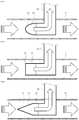
- the fluid containing the foreign substances is divided into a filtered fluid and an unfiltered fluid by the filter, comes into contact with exposed surfaces of upstream sides of the foreign substances stuck in the openings more than exposed surfaces of downstream sides of the foreign substances, so that the fluid flows faster on the exposed surfaces of the upstream sides than on the exposed surfaces of the downstream sides. Therefore, the foreign substances stuck in the openings are separated from the openings, due to a lift force which is based on a Bernoulli principle and is generated with respect to the foreign substances stuck to the openings. Accordingly, even when a filtering process for the fluid is performed for a long time, the openings formed in the filter may not be clogged, thereby providing effects that the filtering process can be continuously performed without replacing the filter or cleaning the filter.
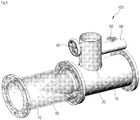
- FIG. 1 a filter assembly according to one embodiment of the present invention is indicated as numeral 100.
- the filter assembly 100 includes: a flow pipe 10 communicably interposed in a portion of a transfer pipe (not shown) through which a fluid containing solid foreign substances is transferred; a branch pipe 20, for example, in a form of a pitot tube, having a size smaller than a size of the flow pipe 10 and being interposed in a part of the flow pipe 10 to form two flow paths in the flow pipe 10 in conjunction with the flow pipe 10, so that an upstream end of the branch pipe 20 is disposed inside the flow pipe 10 and a downstream end of the branch pipe 20 is disposed outside the flow pipe 10; a filter portion 30 connected to the upstream end of the branch pipe 20 disposed in the flow pipe 10, to inclinedly extend with respect to a direction in which a fluid flows and communicate with a downstream end of the flow pipe 10 at an upstream end of the flow pipe 10; a first valve 40 disposed on the downstream end of the branch pipe 20 disposed outside the flow pipe 10; a gas supply pipe 50 having a downstream end communicably
- the branch pipe 20 has a size and a shape to configure an unfiltered flow path for a fluid containing foreign substances which flow through the upstream end of the flow pipe 10 and do not pass through the filter portion 30 and a filtered flow path for a fluid from which foreign substances are filtered.
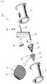
- the filter portion 30 includes: a hollow conical filter 32 that has a plurality of micropores 31 formed in a lattice pattern with an interval of, for example, 1 ⁇ m or less, and is formed by bending a metal plate in a conical shape or by injection molding of a resin material so that a vertex portion thereof is disposed on an upstream side in the direction in which the fluid flows; a plurality of ribs 33 fixedly inscribed on the conical filter 32 to support the conical filter 32; and a connector 34 having an upstream end to which base ends of the plurality of ribs 33 are fixed and a downstream end communicably connected to the upstream end of the branch pipe 20.
- the plurality of micropores 31 formed in the filter 32 are open in a thickness direction of the filter 32 and have a taper shape with a size which gradually decreases from upstream ends to downstream ends.
- the size of the upstream end of each of the micropores 31 is in a range of 10 to 100 ⁇ m and the size of the downstream end of each of the micropores 31 is in a range of 1 to 10 ⁇ m.
- a ratio of the size (width) on the base end side of the conical filter 32 to a length of the conical filter 32 in the flow direction is, for example, 1:2.
- the filter 32 may be made of a nickel alloy material having excellent resistance to chemicals, and may be formed by plating the metal filter 32 made of the nickel alloy material with a tungsten alloy to a thickness of 0.5 to 5 ⁇ m by an electroless plating method to increase the resistance to chemicals to a higher level, or may be made of a resin material such as PP, PE, or PC having resistance to chemicals and durability.
- the flow pipe 10 and the branch pipe 20 may be plated with a tungsten alloy to a thickness of 10 to 40 ⁇ m by an electroless plating method to increase corrosion resistance.
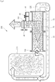
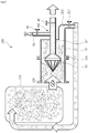
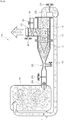
- the filter assembly 100 configured as described above may be applied to a filtering apparatus 200, as shown in FIG. 3 .
- the filtering apparatus 200 includes: a pump 230 and the flow pipe 10 of the filter assembly 100, which are sequentially interposed, in the direction in which the fluids flows, in a portion of a circulation line 220 having an upstream end communicably connected to a lower portion of a fluid storage tank 210 storing the fluid and a downstream end communicably connected to an upper portion of the fluid storage tank 210; a filtered fluid storage tank (not shown) connected to the downstream end of the branch pipe 20 of the filter assembly 100; and a gas supply source (not shown) connected to an upstream end of the gas supply pipe 50 of the filter assembly 100.
- the filtering apparatus 200 to which the filter assembly 100 configured as described above is applied, may be operated as follows.
- the pump 230 when the pump 230 is operated in a state in which the first valve 40 opens and the second valve 60 closes, the fluid containing the solid foreign substances flows from the fluid storage tank 210 and goes to an upstream end of the flow pipe 10 to face the filter portion 30.
- a fluid passing through the plurality of micropores 31 of the filter portion 30 among fluids transferred toward the filter portion 30 is transferred to the downstream end of the branch pipe 20 of the filter assembly 100 to be stored in the filtered fluid storage tank as a filtered fluid from which solid foreign substances of 10 ⁇ m or more are filtered.
- a fluid which does not pass through the plurality of micropores 31 of the filter portion 30 among the fluids transferred toward the filter portion 30 is a fluid containing solid foreign substances of 10 ⁇ m or more, and a process of returning the fluid not passing through the plurality of micropores 31 to the fluid storage tank 210 through the downstream end of the flow pipe 10 and a downstream end of the circulation line 220 is repeated. Therefore, the fluid stored in the fluid storage tank 210 is supplied to the filtered fluid storage tank as the filtered fluid from which solid foreign substances of 10 ⁇ m or more are filtered.
- the solid foreign substances may be stuck in the plurality of micropores 31 having the taper shape.
- an area with which the fluid not passing through the filter 32 and flowing along an outer surface of the filter 32 comes into contact with the solid foreign substances stuck in the micropores 31 is larger than an area with which the fluid passing through the filter 32 and flowing along an inner surface of the filter 32 comes into contact with the solid foreign substances stuck in the micropores 31. Therefore, the foreign substances stuck in the plurality of micropores are separated from the plurality of micropores due to a lift force which is generated with respect to the foreign substances stuck in the plurality of micropores, and return to the fluid storage tank 210. Accordingly, even when a filtering process for the fluid is performed for a long time, the plurality of micropores 31 formed in the filter portion 30 may not be clogged so that the filtering process can be continuously performed without replacing the filter or cleaning the filter.
- the filter assembly 100 can provide an operational effect of continuously performing a filtering process without replacing the filter or a filter cleaning operation.
- the filter 32 of the filter portion 30 is conical, collision between the fluid containing the solid foreign substances and the filter 32 is minimized, so that the flow of the fluid containing the solid foreign substances can be stably maintained.
- ballast water When the size of a downstream end of the plurality of micropores 31 is 3 ⁇ m, drinking water (water not contaminated with chemicals on the ground) can be produced, and when the size thereof is in a range of 10 to 50 ⁇ m, ballast water can be produced.
- the filter assembly 100 and the filtering apparatus 200 having the same can be applied to a wastewater treatment process, a semiconductor process, other particle separation processes, or the like.
- a venturi pipe 250 may be interposed between the pump 230 and the flow pipe 10.
- venturi pipe 250 is interposed between the pump 230 and the flow pipe 10
- a flow rate of the fluid containing the solid foreign substances discharged from the pump 230 rapidly increases as the fluid passes through the venturi pipe 250, and the fluid flows along the outer surface of the filter 32 to generate a larger lift force in the plurality of micropores. Therefore, it is preferable in that the foreign substances stuck in the plurality of micropores are further reliably separated from the plurality of micropores, and the plurality of micropores formed in the filter portion 30 are not further clogged.
- a third valve 221 is installed in a portion of the circulation line 220 positioned on the downstream side of the flow pipe 10
- a fourth valve 251 is installed at a first inlet of the venturi pipe 250 connected to a discharge side of the pump 230
- a fifth valve 252 is installed at a second inlet of the venturi pipe 250 into which outside air is introduced by a negative pressure
- a magnitude of the lift force generated in the plurality of micropores can be adjusted by adjusting an opening degree of the first, third, fourth or fifth valve.
- the filter portion 30 of the filter assembly 100 is described as being conical in the above-described embodiment, the present invention is not limited thereto, and as another embodiment, as shown in FIG. 4 , the filter portion 30 may have a dome shape, as shown in FIG. 5 , a tubular shape having a plurality of micropores 31 formed in a periphery thereof, or as shown in FIG. 6 , a combination type in which a conical portion and a tubular portion are coupled to each other.
- the branch pipe 20 is described as being connected to the flow pipe 10 in the form of a pitot tube, that is, the upstream end of the branch pipe 20 is connected to the flow pipe 10 in such a manner that the upstream end of the filtering pipe 20 extends parallel to the direction in which the fluid flows in the above-described embodiment, but the present invention is not limited thereto.
- the filter 32 of the filter portion 30 is formed in a plate shape to be installed on the upstream end of the branch pipe 20 to be inclined in the direction in which the fluid flows.
- the filter 32 of the filter portion 30 is formed in a plate shape and installed at the upstream end of the branch pipe 20 in parallel to the direction in which the fluid flows.
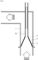
- the branch pipe 20 is described as being connected to a portion of the flow pipe 10 in the form of the L-shaped pitot tube, but the present invention is not limited thereto, and as shown in FIG. 9 , a straight tube type branch pipe 20' can be substituted for the L-shaped pitot tube type branch pipe 20.
- an upstream end of the branch pipe 20' can be communicably inserted into the flow pipe 10 and a downstream end of the branch pipe 20' communicably connected to the filtered fluid storage tank (not shown) can be disposed outside the flow pipe 10.
- the downstream end of the gas supply pipe 50 can be communicably connected to a downstream end portion of the branch pipe 20' positioned on the upstream side of the first valve 40, the upstream end of the gas supply pipe 50 can be communicably connected to the gas supply source (not shown), and the second valve 60 can be interposed in a part of the gas supply pipe 50.
- the conical filter portion 30 is described as being communicably connected to the upstream end of the branch pipe 20 directly, but the present invention is not limited thereto, and as another embodiment, as shown in FIG. 9 , in order to minimize the flow resistance of the fluid, the upstream end of the branch pipe 20' is provided with a contraction pipe 20a having a size that gradually decreases toward the downstream end thereof so that the conical filter portion 30 can be communicably connected thereto.
- a third valve 221 can be interposed in a portion of the circulation line 220 positioned on a downstream side of the flow pipe 10 to regulate a flow rate and a pressure of the filtered fluid discharged through the first valve 40.
- the conical filter 32 is described being installed at the upstream end of the one branch pipe 20, but the present invention is not limited thereto.
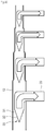
- FIG. 10 in a state in which the flow pipe 10 is formed by connecting a plurality of partial flow pipes having sizes which are gradually reduced from the upstream side to the downstream side, each of a plurality of branch pipes 20 is interposed in a portion of each of the plurality of partial flow pipes.
- the plurality of branch pipes 20 and a plurality of conical filters 32 installed at each of the upstream ends of the plurality of branch pipes 20 have sizes and shapes to form an unfiltered flow path for a fluid containing foreign substances which flow at the upstream end of the plurality of partial flow pipes and do not pass through the plurality of filters 32 and a filtered flow path for a fluid from which foreign substances are filtered.
- the filter assembly of the embodiment of FIG. 10 since the filtered fluid passes through the branch pipe, it is preferable from the viewpoint that a constant flow rate can be stably maintained through the entire length of the flow pipe.
- the plurality of conical filters 32 installed in the filter assembly of the embodiment of FIG. 10 have a plurality of micropores 31 having the size different to each other, particles in the fluid can be separated and discharged by size.
- the filter 32 is described being mounted only on the branch pipe 20, but as shown in FIG. 11 , the filter 32 has a taper shape of which a size is gradually reduced from the upstream end to the downstream end, the upstream end thereof is fixed to the flow pipe 10, the downstream end thereof is fixed to the upstream end of the branch pipe 20, and a plurality of micropores 31 can be formed on a peripheral surface thereof. If the downstream end of the flow pipe 10 is bent from the state of FIG. 11 , as shown in FIG. 12 , the branch pipe 20 is not interposed in the L-shaped pitot tube type in a portion of the flow pipe 10, and becomes a straight tube type branch pipe 20'. Therefore, a downstream end of the branch pipe 20' may pass through a bending portion of the flow pipe 10.
Landscapes
- Chemical & Material Sciences (AREA)
- Chemical Kinetics & Catalysis (AREA)
- Physics & Mathematics (AREA)
- Geometry (AREA)
- Filtering Materials (AREA)
- Separation Using Semi-Permeable Membranes (AREA)
- Lubrication Details And Ventilation Of Internal Combustion Engines (AREA)
Applications Claiming Priority (2)
| Application Number | Priority Date | Filing Date | Title |
|---|---|---|---|
| KR1020170040724A KR101893580B1 (ko) | 2017-03-30 | 2017-03-30 | 필터조립체 |
| PCT/KR2018/003684 WO2018182319A2 (fr) | 2017-03-30 | 2018-03-29 | Ensemble filtre |
Publications (2)
| Publication Number | Publication Date |
|---|---|
| EP3578243A2 true EP3578243A2 (fr) | 2019-12-11 |
| EP3578243A4 EP3578243A4 (fr) | 2020-12-23 |
Family
ID=63678065
Family Applications (1)
| Application Number | Title | Priority Date | Filing Date |
|---|---|---|---|
| EP18776966.6A Withdrawn EP3578243A4 (fr) | 2017-03-30 | 2018-03-29 | Ensemble filtre |
Country Status (6)
| Country | Link |
|---|---|
| US (1) | US20210113951A1 (fr) |
| EP (1) | EP3578243A4 (fr) |
| KR (1) | KR101893580B1 (fr) |
| CN (1) | CN110446540A (fr) |
| CA (1) | CA3054545A1 (fr) |
| WO (1) | WO2018182319A2 (fr) |
Families Citing this family (5)
| Publication number | Priority date | Publication date | Assignee | Title |
|---|---|---|---|---|
| WO2019116681A1 (fr) * | 2017-12-14 | 2019-06-20 | 工機ホールディングス株式会社 | Collecteur de poussière |
| DE102019121342B4 (de) * | 2018-08-15 | 2021-03-18 | Mann+Hummel Gmbh | Filterelement für den Einsatz als Partikelfilter in einem Kühlkreislauf eines elektrochemischen Energiewandlers und Verwendung des Filterelements in einer Anordnung mit einem elektrochemischen Energiewandler und einem Kühlkreislauf |
| KR20210055984A (ko) * | 2019-11-08 | 2021-05-18 | 삼성전자주식회사 | 환기장치 및 이를 포함하는 공기조화기 |
| KR102357909B1 (ko) * | 2019-11-28 | 2022-02-03 | 한국가스공사 | 펌프용 필터 |
| US11938437B2 (en) * | 2021-02-04 | 2024-03-26 | Transportation Ip Holdings, Llc | Filter system and method |
Family Cites Families (14)
| Publication number | Priority date | Publication date | Assignee | Title |
|---|---|---|---|---|
| US4725364A (en) * | 1982-04-05 | 1988-02-16 | Basf Corporation | Laminar flow filtration process |
| DE3716257A1 (de) * | 1987-05-15 | 1988-11-24 | Takeo Imai | Verfahren und vorrichtung zum auffangen verschmutzter substanzen |
| DE102004054246A1 (de) * | 2004-09-27 | 2006-04-06 | Carl Freudenberg Kg | Anordnung für ein plattenförmiges Filterelement in einem Gasfiltergehäuse |
| EP1652565A1 (fr) * | 2004-10-27 | 2006-05-03 | Martin Eurlings | Filtre à flux transversal avec éléments filtrants concentriques |
| KR100628990B1 (ko) | 2004-10-27 | 2006-09-27 | 엘지마이크론 주식회사 | 대면적 일체형 금속필터 |
| KR20070004340A (ko) * | 2005-07-04 | 2007-01-09 | 삼성전자주식회사 | 배관 내장형 필터 및 이를 갖춘 공기조화기 |
| JP2007275893A (ja) * | 2007-06-20 | 2007-10-25 | Eiji Matsumura | 気体混合液生成方法及び気体混合液 |
| WO2009018212A1 (fr) * | 2007-07-30 | 2009-02-05 | Innovative Wireless Technologies, Inc. | Protocole de réseau ad hoc distribué utilisant une signalisation de balise partagée synchrone |
| DE202007011099U1 (de) * | 2007-08-08 | 2008-12-18 | Mann + Hummel Gmbh | Filtereinrichtung |
| JP2011224450A (ja) * | 2010-04-19 | 2011-11-10 | Seiko Epson Corp | 濾過装置 |
| CN201978568U (zh) * | 2011-01-17 | 2011-09-21 | 辽宁裕通石化机械仪表有限公司 | 管道用v形丝网过滤器 |
| JP2014147893A (ja) * | 2013-02-01 | 2014-08-21 | Hitachi Cable Ltd | フィルタ材及びフィルタ材の製造方法 |
| US20150053627A1 (en) * | 2013-08-26 | 2015-02-26 | Hollingsworth & Vose Company | Filter media having an optimized gradient |
| CN105908826A (zh) * | 2016-04-29 | 2016-08-31 | 南昌工程学院 | 一种便于疏通及防堵的城市排水管道 |
-
2017
- 2017-03-30 KR KR1020170040724A patent/KR101893580B1/ko active IP Right Grant
-
2018
- 2018-03-29 WO PCT/KR2018/003684 patent/WO2018182319A2/fr unknown
- 2018-03-29 CN CN201880019203.1A patent/CN110446540A/zh not_active Withdrawn
- 2018-03-29 US US16/498,055 patent/US20210113951A1/en not_active Abandoned
- 2018-03-29 EP EP18776966.6A patent/EP3578243A4/fr not_active Withdrawn
- 2018-03-29 CA CA3054545A patent/CA3054545A1/fr not_active Abandoned
Also Published As
| Publication number | Publication date |
|---|---|
| US20210113951A1 (en) | 2021-04-22 |
| CA3054545A1 (fr) | 2018-10-04 |
| WO2018182319A2 (fr) | 2018-10-04 |
| WO2018182319A3 (fr) | 2018-12-20 |
| EP3578243A4 (fr) | 2020-12-23 |
| KR101893580B1 (ko) | 2018-10-04 |
| CN110446540A (zh) | 2019-11-12 |
Similar Documents
| Publication | Publication Date | Title |
|---|---|---|
| US10639564B2 (en) | Metal filter having no clogging and permanent filter assembly containing metal filter | |
| EP3578243A2 (fr) | Ensemble filtre | |
| US7314560B2 (en) | Cyclone separator | |
| EP2010303B1 (fr) | Dispositif de filtrage fin comprenant un module de filtrage a fibres flexibles | |
| US20100116732A1 (en) | In-line strainer | |
| RU99109568A (ru) | Фильтр | |
| KR20050004769A (ko) | 유동액체로부터 입자 및 유기체의 분리 및 여과하기 위한장치 및 방법 | |
| CA2398461A1 (fr) | Separateur a membrane de type a immersion multi-etage et station d'epuration des eaux usees a haute concentration mettant en oeuvre ce separateur | |
| KR20170021763A (ko) | 여과 장치 및 필터 엘리먼트 | |
| JP2019502539A (ja) | フィルタアセンブリおよび使用方法 | |
| KR20210001678A (ko) | 버켓 타입 스트레이너장치 | |
| KR101998320B1 (ko) | 수처리 설비의 유량 분배 장치 | |
| CN213698973U (zh) | 一种循环水管道过滤器以及过滤系统 | |
| US20230271113A1 (en) | Regenerative media filter with flow diffuser | |
| KR101885724B1 (ko) | 필터청소기능을 구비한 필터조립체 | |
| CN1214851C (zh) | 外压中空纤维膜分离装置及其使用方法 | |
| JP2521389B2 (ja) | インライン型ストレ―ナ | |
| EP2418407B1 (fr) | Buse à flux variable | |
| JP3217975U (ja) | 濾過装置 | |
| US11547971B2 (en) | Ceramic filter membrane module | |
| KR101336665B1 (ko) | 정수기의 유량 조절 장치 및 이를 포함하는 정수기 | |
| JP6077223B2 (ja) | 排水膜濾過装置 | |
| JP2016532540A (ja) | 内部隔壁を有する拡大洗浄ダクトを有するフィルタ装置 | |
| US20170072346A1 (en) | Back-flushable filtered valve | |
| KR102459933B1 (ko) | 상수도관 유지관리 여과시스템 |
Legal Events
| Date | Code | Title | Description |
|---|---|---|---|
| STAA | Information on the status of an ep patent application or granted ep patent |
Free format text: STATUS: THE INTERNATIONAL PUBLICATION HAS BEEN MADE |
|
| PUAI | Public reference made under article 153(3) epc to a published international application that has entered the european phase |
Free format text: ORIGINAL CODE: 0009012 |
|
| STAA | Information on the status of an ep patent application or granted ep patent |
Free format text: STATUS: REQUEST FOR EXAMINATION WAS MADE |
|
| 17P | Request for examination filed |
Effective date: 20190903 |
|
| AK | Designated contracting states |
Kind code of ref document: A2 Designated state(s): AL AT BE BG CH CY CZ DE DK EE ES FI FR GB GR HR HU IE IS IT LI LT LU LV MC MK MT NL NO PL PT RO RS SE SI SK SM TR |
|
| AX | Request for extension of the european patent |
Extension state: BA ME |
|
| DAV | Request for validation of the european patent (deleted) | ||
| DAX | Request for extension of the european patent (deleted) | ||
| A4 | Supplementary search report drawn up and despatched |
Effective date: 20201123 |
|
| RIC1 | Information provided on ipc code assigned before grant |
Ipc: B01D 46/00 20060101ALI20201117BHEP Ipc: B01D 39/00 20060101AFI20201117BHEP Ipc: B01D 35/30 20060101ALI20201117BHEP Ipc: B01D 29/66 20060101ALI20201117BHEP Ipc: B01D 29/085 20060101ALI20201117BHEP |
|
| STAA | Information on the status of an ep patent application or granted ep patent |
Free format text: STATUS: THE APPLICATION IS DEEMED TO BE WITHDRAWN |
|
| 18D | Application deemed to be withdrawn |
Effective date: 20210622 |