EP3578041B1 - Dispenser device and corresponding method and use for mite control in beehives - Google Patents
Dispenser device and corresponding method and use for mite control in beehives Download PDFInfo
- Publication number
- EP3578041B1 EP3578041B1 EP18176891.2A EP18176891A EP3578041B1 EP 3578041 B1 EP3578041 B1 EP 3578041B1 EP 18176891 A EP18176891 A EP 18176891A EP 3578041 B1 EP3578041 B1 EP 3578041B1
- Authority
- EP
- European Patent Office
- Prior art keywords
- evaporation
- formic acid
- container
- honeycomb
- evaporation container
- Prior art date
- Legal status (The legal status is an assumption and is not a legal conclusion. Google has not performed a legal analysis and makes no representation as to the accuracy of the status listed.)
- Active
Links
- 238000000034 method Methods 0.000 title claims description 19
- BDAGIHXWWSANSR-UHFFFAOYSA-N methanoic acid Natural products OC=O BDAGIHXWWSANSR-UHFFFAOYSA-N 0.000 claims description 166
- 238000001704 evaporation Methods 0.000 claims description 143
- 230000008020 evaporation Effects 0.000 claims description 142
- OSWFIVFLDKOXQC-UHFFFAOYSA-N 4-(3-methoxyphenyl)aniline Chemical compound COC1=CC=CC(C=2C=CC(N)=CC=2)=C1 OSWFIVFLDKOXQC-UHFFFAOYSA-N 0.000 claims description 83
- 235000019253 formic acid Nutrition 0.000 claims description 83
- 244000144987 brood Species 0.000 claims description 51
- 239000007788 liquid Substances 0.000 claims description 43
- 238000002360 preparation method Methods 0.000 claims description 28
- 238000003860 storage Methods 0.000 claims description 26
- 238000011282 treatment Methods 0.000 claims description 25
- 230000004888 barrier function Effects 0.000 claims description 20
- 210000001520 comb Anatomy 0.000 claims description 17
- 239000012528 membrane Substances 0.000 claims description 17
- 238000004806 packaging method and process Methods 0.000 claims description 5
- 239000000463 material Substances 0.000 claims description 4
- 230000002209 hydrophobic effect Effects 0.000 claims description 3
- 241000895647 Varroa Species 0.000 claims 1
- 238000010276 construction Methods 0.000 claims 1
- 238000003780 insertion Methods 0.000 claims 1
- 230000037431 insertion Effects 0.000 claims 1
- 239000007787 solid Substances 0.000 claims 1
- 241000264877 Hippospongia communis Species 0.000 description 46
- XLYOFNOQVPJJNP-UHFFFAOYSA-N water Chemical compound O XLYOFNOQVPJJNP-UHFFFAOYSA-N 0.000 description 9
- 239000007789 gas Substances 0.000 description 8
- 238000009826 distribution Methods 0.000 description 7
- 241000256844 Apis mellifera Species 0.000 description 6
- 239000011148 porous material Substances 0.000 description 5
- 241000257303 Hymenoptera Species 0.000 description 4
- 238000010306 acid treatment Methods 0.000 description 4
- 230000000694 effects Effects 0.000 description 4
- 230000035699 permeability Effects 0.000 description 4
- MUBZPKHOEPUJKR-UHFFFAOYSA-N Oxalic acid Chemical compound OC(=O)C(O)=O MUBZPKHOEPUJKR-UHFFFAOYSA-N 0.000 description 3
- 239000004743 Polypropylene Substances 0.000 description 3
- 238000010521 absorption reaction Methods 0.000 description 3
- 230000008901 benefit Effects 0.000 description 3
- 238000009833 condensation Methods 0.000 description 3
- 230000005494 condensation Effects 0.000 description 3
- 230000001419 dependent effect Effects 0.000 description 3
- 238000010790 dilution Methods 0.000 description 3
- 239000012895 dilution Substances 0.000 description 3
- 239000004744 fabric Substances 0.000 description 3
- 239000011094 fiberboard Substances 0.000 description 3
- 239000000203 mixture Substances 0.000 description 3
- -1 polypropylene Polymers 0.000 description 3
- 229920001155 polypropylene Polymers 0.000 description 3
- 125000006850 spacer group Chemical group 0.000 description 3
- 241000238876 Acari Species 0.000 description 2
- 241000243142 Porifera Species 0.000 description 2
- 230000007423 decrease Effects 0.000 description 2
- 239000003814 drug Substances 0.000 description 2
- 239000006260 foam Substances 0.000 description 2
- 238000010438 heat treatment Methods 0.000 description 2
- 239000004816 latex Substances 0.000 description 2
- 229920000126 latex Polymers 0.000 description 2
- 238000011866 long-term treatment Methods 0.000 description 2
- 230000003071 parasitic effect Effects 0.000 description 2
- 230000001105 regulatory effect Effects 0.000 description 2
- 239000000758 substrate Substances 0.000 description 2
- KXGFMDJXCMQABM-UHFFFAOYSA-N 2-methoxy-6-methylphenol Chemical compound [CH]OC1=CC=CC([CH])=C1O KXGFMDJXCMQABM-UHFFFAOYSA-N 0.000 description 1
- 206010061217 Infestation Diseases 0.000 description 1
- 241001267704 Oxyphanes Species 0.000 description 1
- 239000004793 Polystyrene Substances 0.000 description 1
- 241001558516 Varroa destructor Species 0.000 description 1
- 241000607479 Yersinia pestis Species 0.000 description 1
- 230000002745 absorbent Effects 0.000 description 1
- 239000002250 absorbent Substances 0.000 description 1
- 239000002253 acid Substances 0.000 description 1
- 230000004913 activation Effects 0.000 description 1
- XAGFODPZIPBFFR-UHFFFAOYSA-N aluminium Chemical compound [Al] XAGFODPZIPBFFR-UHFFFAOYSA-N 0.000 description 1
- 229910052782 aluminium Inorganic materials 0.000 description 1
- 238000009835 boiling Methods 0.000 description 1
- 230000008859 change Effects 0.000 description 1
- 239000004020 conductor Substances 0.000 description 1
- 230000001276 controlling effect Effects 0.000 description 1
- 230000003247 decreasing effect Effects 0.000 description 1
- 230000006735 deficit Effects 0.000 description 1
- HQVFCQRVQFYGRJ-UHFFFAOYSA-N formic acid;hydrate Chemical compound O.OC=O HQVFCQRVQFYGRJ-UHFFFAOYSA-N 0.000 description 1
- 238000003306 harvesting Methods 0.000 description 1
- 231100001261 hazardous Toxicity 0.000 description 1
- 230000036541 health Effects 0.000 description 1
- 231100000086 high toxicity Toxicity 0.000 description 1
- 235000012907 honey Nutrition 0.000 description 1
- 230000010354 integration Effects 0.000 description 1
- 210000004072 lung Anatomy 0.000 description 1
- 238000004519 manufacturing process Methods 0.000 description 1
- 201000002266 mite infestation Diseases 0.000 description 1
- 235000006408 oxalic acid Nutrition 0.000 description 1
- 239000000123 paper Substances 0.000 description 1
- 229920001568 phenolic resin Polymers 0.000 description 1
- 239000005011 phenolic resin Substances 0.000 description 1
- 239000004033 plastic Substances 0.000 description 1
- 239000002985 plastic film Substances 0.000 description 1
- 229920006255 plastic film Polymers 0.000 description 1
- 229920000098 polyolefin Polymers 0.000 description 1
- 229920001296 polysiloxane Polymers 0.000 description 1
- 229920002223 polystyrene Polymers 0.000 description 1
- 230000008569 process Effects 0.000 description 1
- 230000001681 protective effect Effects 0.000 description 1
- 230000000630 rising effect Effects 0.000 description 1
- 229920006395 saturated elastomer Polymers 0.000 description 1
- 230000035939 shock Effects 0.000 description 1
- 238000002633 shock therapy Methods 0.000 description 1
- 239000000243 solution Substances 0.000 description 1
- 230000004083 survival effect Effects 0.000 description 1
- 230000008961 swelling Effects 0.000 description 1
- 231100000331 toxic Toxicity 0.000 description 1
- 231100000816 toxic dose Toxicity 0.000 description 1
- 230000002588 toxic effect Effects 0.000 description 1
Images


Classifications
-
- A—HUMAN NECESSITIES
- A01—AGRICULTURE; FORESTRY; ANIMAL HUSBANDRY; HUNTING; TRAPPING; FISHING
- A01K—ANIMAL HUSBANDRY; CARE OF BIRDS, FISHES, INSECTS; FISHING; REARING OR BREEDING ANIMALS, NOT OTHERWISE PROVIDED FOR; NEW BREEDS OF ANIMALS
- A01K51/00—Appliances for treating beehives or parts thereof, e.g. for cleaning or disinfecting
Definitions
- the so-called short-term treatment with formic acid vapor in which, for example, a sponge cloth soaked with formic acid is inserted into a cavity above or below the honeycomb of the beehive, can be called shock therapy because initially high formic acid vapor concentrations occur in the hive for a short time (Liebig 2011).
- shock therapy because initially high formic acid vapor concentrations occur in the hive for a short time (Liebig 2011).
- a better regulated steam release is achieved with the help of the Krämer plate, in which the formic acid is bound to a soft fiber board and the evaporation area can be adapted to requirements by means of the number and size of evaporation windows in an enveloping plastic film. Since the degree of swelling of the fiberboard influences the vapor pressure and the permeability of the formic acid, the evaporation rate also decreases significantly with this dispenser over time.
- a strong initial concentration of formic acid vapor is also achieved with the Mite Away Quick Strips (MAQS), according to the patent application US 2008 / 0280528A1 reached, which are placed in a cavity under the lid of the hive.
- the MAQS dispenser binds the formic acid to a gel cushion with a wick-like evaporation surface, which is limited by an evaporation window in an envelope. It combines a short-term shock effect with a longer-lasting and gradually decreasing release of formic acid vapor and, in addition to the advantage of being relatively effective against mites, has application advantages (Aumeier et al. 2011).
- the Nassenheider dispenser ( EP 0 959 674 B1 ), developed the use of formic acid with medicine bottles and the Liebig dispenser (Liebig 2011).
- the formic acid preparation is transferred from a storage container to a wick and evaporation takes place on a capillary suction evaporation surface, e.g. a sponge cloth or filter paper, the evaporation surface gradually increasing to a certain value.
- a capillary suction evaporation surface e.g. a sponge cloth or filter paper
- compositions, devices and methods for controlling pests using steam activity are described.
- the device has a substrate impregnated with the composition, an impermeable housing with one or more openings for releasing vapors from the substrate and additionally has a removable pull-tab of flexible vapor-impermeable sheet material to controllably open the openings for releasing the vapors by a user to enable.
- Ruzicka describes in US 6,837,770 B2 a dispenser in the form of a plate with a core, consisting of open-pored formic acid-resistant organic foam, for example made of phenolic resin foam. The core, which is still dry, is initially wrapped in a liquid-impermeable film.
- the wrapped plate is cut into two halves and the core of the halves is capillary saturated with the liquid formic acid preparation.
- the cut surface acts as an evaporation window.
- One advantage of this dispenser is its ease of use and the high volume-related capacity of the core for the formic acid preparation.
- Most of the formic acid dispensers used to date use the space of an empty frame as the steam distribution space. With the Nassenheider dispenser in the vertical application form and with the dispenser according to Burmeister (Charriere J-D, 1998), the distribution space is an empty honeycomb frame on the edge of the brood nest.
- the dispenser after US 6,837,770 B2 is fixed in a vertical position in a space between the loot wall and the outer frame, with the evaporation surface at the bottom.
- the evaporation surface is adjacent to a distribution space for the formic acid vapor, the air of which is far below the brood nest temperature in cool weather and has a high relative humidity.
- the formic acid steam treatment of the colonies is usually carried out in late summer directly after the honey harvest and a second time after feeding. At the times mentioned (in Central Europe from the end of July to the beginning of September) the infestation with the parasitic mite is particularly strong.
- Amrine J and Noel R (2006) describe a formic acid dispenser in which the evaporation surface borders on an air space above the honeycomb and faces the honeycomb, so that the evaporation surface is flowed through by the air heated in the brood nest.
- This dispenser has a wooden frame to be placed on the frame with the honeycomb frame as well as a wooden inner frame to be used in this frame, which is covered with an aluminum sheet or a plastic plate at the top, except for a narrow bee path.
- An absorbent fabric for capillary binding of the formic acid preparation is attached under the cover with the aid of a grid.
- the moist tissue is flown against by the rising warm air and releases formic acid vapor into the vapor distribution space called the activation cavity above the honeycomb, which is delimited by the inner frame.
- the activation cavity above the honeycomb which is delimited by the inner frame.
- a sufficiently high evaporation rate in cold weather is achieved when using the medicine bottle in conjunction with a soft fiber board (Liebig 2011). Since the plate placed on the honeycomb frame of the brood nest is in direct contact with the brood nest, it releases the formic acid vapor directly into the honeycomb lanes covered by it on its underside, which is heated by the brood nest.
- This membrane is covered with a vapor-tight film before the dispenser is used.
- the problem of possible skin contact with formic acid has not yet been solved in that the gas-permeable and liquid-impermeable membrane is covered by a gas-impermeable layer. In this case, too, the outside of the gas-permeable liquid barrier can be moistened with the formic acid preparation due to condensation.
- the object of the invention is to provide a user-friendly dispenser for formic acid vapor in beehives, which allows an evaporation rate largely independent of the outside climate without additional heating while avoiding the disadvantages mentioned above.
- Another object is to provide a convenient, inexpensive, and risk free method of formic acid treatment of beehives.
- the object is achieved according to the invention by a dispenser for formic acid vapor according to one of claims 1 to 5 in conjunction with a method for treating a bee hive for mite control according to one of claims 6-13 and use claims 14-15.
- FIG. 1 Essential features of the dispenser according to the invention are from Figure 1 evident. It contains two interconnected compartments for introducing a liquid formic acid preparation, one of which is limited to the outside in whole or in part by the evaporation surface and is referred to below as evaporation container 1, and another compartment which is gas-tight to the outside and is hereinafter referred to as a storage container 2 is designated.
- the dimensions of the evaporation container make it possible to place it in an air space directly adjacent to the brood nest combs and honeycomb lanes 3 of the brood nest or located in a honeycomb lane without expanding the volume of the prey and without using an empty frame, while the evaporation surface 4 is in the air space of a honeycomb lane or in an air flow path integrated into the evaporation container through the brood nest.
- the evaporation area is limited by a layer that is impermeable to the liquid formic acid preparation but highly permeable to its vapor and other gases, which is referred to as a gas-permeable liquid barrier.
- a gas-permeable liquid barrier in the form of a highly porous flat membrane or tubular membrane made of a hydrophobic material, for example a polyolefin, is suitable for delimiting the evaporation surface.
- Gas-permeable liquid barriers with the properties mentioned find numerous applications, for example for production waterproof gas permeable clothing, passive valves, porous spacers, and devices for gas exchange with liquids such as artificial lungs and the like. For example, they are available as industrial mass products made from polypropylene with the brand names Accurel®, Celgard®, Oxyphan® and Treo-Pore®.
- the gas-permeable liquid barrier for the use according to the invention like the aforementioned porous polypropylene membranes, consists of a hydrophobic material.
- the evaporation container is in direct contact with the honeycomb or it is located in a honeycomb alley or it lies on the upper girders of the honeycomb frames.
- the evaporation container is in a close, heat-conducting connection with the brood nest so that its temperature is determined to a greater extent by the brood nest temperature than the outside temperature.
- the method according to the invention dispenses with a wide air space for distributing the formic acid vapor in the prey, the temperature of which is significantly below the temperature of the brood nest combs. This eliminates the condensation of water on the evaporation surface.
- the method according to the invention for treating a bee hive for mite control comprises the placing of an evaporation container in the hive in connection with the exposure of its evaporation surface in a honeycomb lane with a normal width of up to 12 mm, an equally narrow space between the brood nest frame and the hive roof or a further frame or into an air flow path integrated into the evaporation container, which leads through the brood nest. Placing the evaporation container in an air space adjacent to the brood nest enables the formic acid vapor to be released into the air, which is thermally or mechanically moved by the bee activity and which is characterized by a high water vapor saturation deficit.
- the evaporation container is suspended from above in a honeycomb lane of the brood nest and connected to a storage container by a closable liquid conductor, which is designed as a two-dimensionally extended container in accordance with the Figure 1 is placed on the upper beam of the honeycomb frame.
- a closable liquid conductor which is designed as a two-dimensionally extended container in accordance with the Figure 1 is placed on the upper beam of the honeycomb frame.
- the storage container can also be placed outside the hive, with the connecting line, for example, being led through the hive wall or an entrance hole.
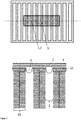
- the evaporation container can be placed on the honeycomb frame above the brood nest, with the evaporation surface on the air space of several Honeycomb lanes bordered, as in Figure 2 is shown schematically. This distributes the steam from above into several honeycomb lanes at the same time.
- covering the evaporation container with a heat-insulating layer is advantageous for maintaining the temperature on the evaporation surface when the outside climate is cool.
- the evaporation container can be in the honeycomb alley accordingly Figure 3 , above, or another space between two honeycomb frames. It borders the honeycombs on both sides of the Wabengasse, as in Figure 3 in the middle. In the latter case, the evaporation container is fixed in its position, for example when the still empty honeycomb frames are suspended, and the treatment dose is introduced into the evaporation container after the brood combs have been built. The evaporation container is placed in such a way that it is surrounded by brood nest combs during treatment and its evaporation surface is adjacent to the integrated air flow channel.
- the evaporation container can be designed in such a way that the air flow channel is surrounded by a flexible inner wall in which the gas-permeable liquid barrier is integrated, an elastic screen mesh 9 and a flexible, liquid-tight outer wall, as in FIG Figure 3 , shown below.
- the evaporation container can easily be inserted into the honeycomb lane, where it is elastically fixed.
- the integration of the air flow path in the evaporation container makes it possible to conduct the gas laden with the formic acid vapor thermally upwards and to distribute it in the bag air over the honeycombs without the risk of a local formic acid vapor concentration that is toxic to bees.
- the illustrated embodiments of the evaporation container is in thermally conductive contact with the brood combs delimiting the honeycomb lane.
- the connecting line between the storage container and the evaporation container can be closed, the treatment dose of the formic acid preparation can first be enclosed in the vapor-tight storage container.
- An advantageous way of doing this is in Figure 4 shown schematically.
- the already filled, stackable dispenser is suitable for storage and distribution before the connection line is opened.
- the connecting line opens by pulling it out of the clamp 6 and the liquid formic acid preparation can be transferred to the evaporation container.
- the formic acid vapor release rate of about 10 g per day recommended for high mite mortality is already achieved with an evaporation area of 10 cm 2 when prototypes of the dispenser according to the invention at a temperature of 35 ° C in slowly moving dry air can be used with a formic acid concentration of 60%.
- the area-dependent evaporation rate achieved similarly high values and was far above the area-dependent evaporation rate of previously known dispensers, such as the in Figure 1
- the prototypes of the evaporation container shown schematically below were introduced into the honeycomb lane of a beehive during the late summer. This shows that a further vapor distribution space outside the honeycomb space is not required to avoid vapor saturation on the evaporation surface. The explanation for this could be an unexpectedly high flow velocity of the air through the brood nest.
- Evaporation container made of polypropylene of the in Figure 3 above, the design shown with an evaporation area of 9 cm 2 , the evaporation window of which was closed by a gas-permeable liquid barrier in the form of the 25 ⁇ m thick Treo-Pore® membrane PDA 25, were filled with a silicone hose and a storage vessel in the form of a graduated 25 ml Pipette connected.
- the evaporation containers were hung in a heated, ventilated air space with a temperature of 35 ° C and a constant supply of fresh air. The hourly rate of evaporation of 60% formic acid in the pipettes was determined by reading off the volume of the liquid.
- the evaporation rate based on the evaporation area was 52 to 62 mm 3 cm -2 h -1 .
- a daily evaporation capacity of over 10 ml per day was already achieved with an evaporation area of less than 10 cm 2 .
- the formic acid dispenser described was tested in late summer in several beehives consisting of two boxes, with a connecting hose being passed through the hive wall.
- the evaporation rate based on the area was 21 to 25 mm 3 cm -2 h -1 . This achieved the recommended daily release rate of 6 to 10 cm 3 for effective treatment with an evaporation area of only 15 cm 2 .
- Figure 1 shows schematically a dispenser whose evaporation container 1 (below) is connected to a storage container 2 (above).
- the evaporation container is located in the honeycomb lane 3, in which it exposes the evaporation surface 4 delimited by the gas-permeable liquid barrier.
- the evaporation container is connected by a connecting line 5 to the storage container, a flat container with a capacity of approximately 120 cm 3 and a base area of approximately 200 cm 2 .
- the entire treatment dose of the liquid formic acid preparation is in the gas-tight before treatment sealed storage container.
- the liquid formic acid preparation is fed into the evaporation container by opening clamp 6.
- Figure 2 shows schematically an evaporation container which is placed on the honeycomb frame 11 and is covered by a heat-insulating layer 7.
- a heat-insulating layer 7 Above: Top view of the honeycomb frames, the honeycomb lanes and the evaporation container. The evaporation surface bounded by the gas-permeable liquid barrier rests on the upper girders 12 of the honeycomb frames and is exposed in the air space of the honeycomb alleys of the brood nest.
- Figure 3 shows a schematic representation of a section through two honeycomb frames with evaporation containers with different positions of the evaporation surfaces, which are delimited by a gas-permeable liquid barrier.
- the evaporation container was placed in the honeycomb alley to treat the beehive and exposes two evaporation surfaces in the honeycomb alley. Spacers 13 ensure a defined air flow path and good heat conduction and prevent the evaporation window from contacting the honeycomb.
- Middle Before the honeycomb was built, the evaporation tank was placed in the space between the central walls 14 of two honeycomb frames. During the treatment period, it adjoins the honeycombs of both frames and envelops an air flow path 8 through the brood nest, which is separated from the honeycomb alley.
- the evaporation container has an integrated air flow path, a flexible outer wall impermeable to formic acid vapor and a flexible inner wall into which the evaporation surface is integrated. In the position of the evaporation surface, the inner wall is formed by a gas-permeable liquid barrier.
- the evaporation container contains an elastic screen mesh 9 made of polystyrene to ensure the distance between the outer and inner walls and to ensure elasticity.
- FIG. 4 shows a schematic representation of a longitudinal section through a dispenser according to the invention with a clamping device which opens when the evaporation container is removed from the packaging 10.
- a clamping device which opens when the evaporation container is removed from the packaging 10.
- the connecting line 5 between the storage container 2 and the evaporation container 1 is tightly clamped off with a clamp 6.
- the liquid formic acid preparation is only located in the storage container and the part of the connecting line that is between the clamp and the storage container.
- the clamp prevents the formic acid preparation from being transferred to the evaporation container.
- the connection line was stretched and pulled out of the clamp.
- the formic acid preparation can be transferred to the evaporation container through the connecting line that is thus opened. Through This process can be supported by mechanical pressure on the flexible wall of the storage container.
Description
Die Behandlung von Bienenbeuten mit Ameisensäuredampf hat u.a. in Europa, den USA und Kanada wirtschaftliche Bedeutung. Sie ist ein Bestandteil, der für das Überleben der Bienenvölker erforderlichen Bekämpfung der parasitischen Milbe Varroa destructor und wird unter Verwendung verschiedener Dispenser für Ameisensäuredampf in Deutschland vor allem im Spätsommer und Herbst durchgeführt und häufig mit einer Oxalsäure-Behandlung im Winter kombiniert. Bei der Ameisensäuredampfbehandlung kommt es vor allem darauf an, den Milbenbefall der Larven in den Brutwaben zu reduzieren, in welche die Ameisensäure nur in der Form ihres Dampfes eindringt.The treatment of beehives with formic acid vapor is of economic importance in Europe, the USA and Canada, among others. It is part of the control of the parasitic mite Varroa destructor , which is necessary for the survival of the bee colonies and is carried out in Germany primarily in late summer and autumn using various dispensers for formic acid vapor and is often combined with oxalic acid treatment in winter. In the case of formic acid steam treatment, the main thing is to reduce the mite infestation of the larvae in the brood combs, into which the formic acid only penetrates in the form of its vapor.
Die sogenannte Kurzzeitbehandlung mit Ameisensäuredampf, bei der beispielsweise ein mit Ameisensäure getränktes Schwammtuch in einen Hohlraum über oder unter den Waben der Bienenbeute eingesetzt wird, kann als Schock-Therapie bezeichnet werden, weil anfangs kurzzeitig hohe Ameisensäuredampfkonzentrationen in der Beute auftreten (Liebig 2011). Eine besser regulierte Dampfabgabe wird mit Hilfe der Krämerplatte erreicht, bei welcher die Ameisensäure an eine Weichfaserplatte gebunden ist und die Verdunstungsfläche durch die Zahl und Größe von Verdunstungsfenstern in einer umhüllenden Plastikfolie an den Bedarf angepasst werden kann. Da der Quellungsgrad der Faserplatte den Dampfdruck und die Permeabilität der Ameisensäure beeinflusst, nimmt auch bei diesem Dispenser die Verdunstungsrate mit der Zeit deutlich ab. Eine starke Anfangskonzentration des Ameisensäuredampfes wird auch mit den Mite Away Quick Strips (MAQS), entsprechend der Patentanmeldung
Die bisher genannten Disperser sind bei fahrlässigem Einsatz gesundheitsgefährdend, weil entweder mit der offenen Säure oder mit Oberflächen des Dispensers hantiert werden muss, die mit dem Ameisensäurepräparat befeuchtet sind. Die notwendigen Vorsichtsmaßnahmen und die erforderliche Schutzbekleidung komplizieren die Durchführung der Ameisensäure-Behandlung. Aus diesem Grunde und zur Kontrolle der Verdunstungsrate wurde durch Daniels et al. (1999) die Verwendung eines Dispensers mit membrankontrollierter Verdunstung unter Verwendung einer dampfdurchlässigen und flüssigkeitsundurchlässigen Latexmembran vorgeschlagen. Auch in der Patentanmeldung
Die Aufgabe der Erfindung besteht in der Bereitstellung eines anwenderfreundlichen Dispensers für Ameisensäuredampf in Bienenbeuten, der eine vom Außenklima weitgehend unabhängige Verdunstungsrate ohne zusätzliche Heizung unter Vermeidung der oben genannten Nachteile ermöglicht. Eine weitere Aufgabe besteht in der Bereitstellung eines bequemen, kostengünstigen und risikofreien Verfahrens der Ameisensäurebehandlung von Bienenbeuten. Die Aufgabe wird erfindungsgemäß durch einen Dispenser für Ameisensäuredampf nach einem der Ansprüche 1 bis 5 in Verbindung mit einem Verfahren zur Behandlung einer Bienenbeute zur Milbenbekämpfung nach einem der Ansprüche 6-13 und Verwendungsansprüche 14-15 gelöst.The object of the invention is to provide a user-friendly dispenser for formic acid vapor in beehives, which allows an evaporation rate largely independent of the outside climate without additional heating while avoiding the disadvantages mentioned above. Another object is to provide a convenient, inexpensive, and risk free method of formic acid treatment of beehives. The object is achieved according to the invention by a dispenser for formic acid vapor according to one of
Wesentliche Merkmale des erfindungsgemäßen Dispensers sind aus
Das erfindungsgemäße Verfahren zur Behandlung einer Bienenbeute zur Milbenbekämpfung umfasst das Platzieren eines Verdunstungsbehälters in der Beute in Verbindung mit dem Exponieren seiner Verdunstungsfläche in eine Wabengasse einer normalen Weite bis 12 mm, einen ebenso engen Raum zwischen den Brutnestwabenrahmen und dem Beutedach bzw. einer weiteren Zarge oder in einen in den Verdunstungsbehälter integrierten Luftströmungsweg, der durch das Brutnest führt. Das Platzieren des Verdunstungsbehälters in einen an das Brutnest angrenzenden Luftraum ermöglicht die Abgabe des Ameisensäuredampfes an die durch die Bienenaktivität thermisch oder mechanisch bewegte Luft, die durch ein hohes Wasserdampfsättigungsdefizit ausgezeichnet ist. Eine effektive Wärmeleitung von den Brutnestwaben, deren Temperatur ca. 35 °C beträgt, zum Verdunstungsbehälter bedingt einen hohen und annähernd konstanten Dampfdruck der Ameisensäure an der Verdunstungsfläche. Die auf einen Wert von etwa 40 % durch die Bienen einregulierte relative Luftfeuchtigkeit liegt unter der relativen Luftfeuchtigkeit einer 60 %igen Lösung von Ameisensäure in Wasser, so dass die oberflächliche kondensationsbedingte Verdünnung der Ameisensäure vermieden wird. So wird eine Verdunstungsrate möglich, die relativ unabhängig vom Außenklima ist. Diese Rate wird im Wesentlichen von der Luftströmung nahe der Verdunstungsfläche und deren Geometrie bestimmt.The method according to the invention for treating a bee hive for mite control comprises the placing of an evaporation container in the hive in connection with the exposure of its evaporation surface in a honeycomb lane with a normal width of up to 12 mm, an equally narrow space between the brood nest frame and the hive roof or a further frame or into an air flow path integrated into the evaporation container, which leads through the brood nest. Placing the evaporation container in an air space adjacent to the brood nest enables the formic acid vapor to be released into the air, which is thermally or mechanically moved by the bee activity and which is characterized by a high water vapor saturation deficit. An effective heat conduction from the brood nest combs, whose temperature is approx. 35 ° C, to the evaporation container requires a high and almost constant vapor pressure of the formic acid on the evaporation surface. The relative humidity, regulated by the bees to a value of around 40%, is below the relative humidity of a 60% solution of formic acid in water, so that the superficial, condensation-related dilution of the formic acid is avoided. This enables an evaporation rate that is relatively independent of the outside climate. This rate is essentially determined by the air flow near the evaporation surface and its geometry.
Beispielsweise wird der Verdunstungsbehälter von oben in eine Wabengasse des Brutnestes eingehängt und durch einen verschließbaren Flüssigkeitsleiter mit einem Vorratsbehälter verbunden, der als flächig ausgedehnter Behälter entsprechend der
Erfindungsgemäß kann der Verdunstungsbehälter auf die Wabenrahmen über dem Brutnest aufgelegt werden, wobei die Verdunstungsfläche an den Luftraum mehrerer Wabengassen grenzt, wie in
Der Verdunstungsbehälter kann in der Wabengasse entsprechend
Ist die Verbindungsleitung zwischen dem Vorratsbehälter und dem Verdunstungsbehälter verschließbar, kann die Behandlungsdosis des Ameisensäurepräparates zunächst im dampfdichten Vorratsbehälter eingeschlossen werden. Hierdurch besteht die Möglichkeit, dass der Imker einen vorgefertigten bereits mit der Behandlungsdosis gefüllten Dispenser gefahrlos einsetzt. Eine vorteilhafte Möglichkeit hierzu ist in
Überraschend und unerwartet zeigte sich, dass die für eine hohe Milbenmortalität empfohlene Ameisensäuredampf-Abgaberate von etwa 10 g pro Tag bereits mit einer Verdunstungsfläche von 10 cm2 erreicht wird, wenn Prototypen des erfindungsgemäßen Dispensers bei einer Temperatur von 35 °C in langsam bewegter trockener Luft mit einer Ameisensäurekonzentration von 60 % eingesetzt werden. Die flächenabhängige Verdunstungsrate erreichte ähnlich hohe Werte und lag weit über der flächenabhängigen Verdunstungsrate bisher bekannter Dispenser, als die in
Aus Polypropylen gefertigte Verdunstungsbehälter der in
Oben: Aufsicht auf die Wabenrahmen, die Wabengassen und den Verdunstungsbehälter. Die von der gasdurchlässigen Flüssigkeitsbarriere begrenzte Verdunstungsfläche liegt den Oberträgern 12 der Wabenrahmen auf und ist in den Luftraum der Wabengassen des Brutnestes exponiert. Unten: Ausschnitt aus einem Schnitt durch den Verdunstungsbehälter senkrecht zum Verlauf der Wabenrahmen.
Above: Top view of the honeycomb frames, the honeycomb lanes and the evaporation container. The evaporation surface bounded by the gas-permeable liquid barrier rests on the
- 11
- VerdunstungsbehälterEvaporation tank
- 22
- VorratsbehälterStorage container
- 33
- WabengasseWabengasse
- 44th
- VerdunstungsflächeEvaporation area
- 55
- VerbindungsleitungConnecting line
- 66th
- KlemmeClamp
- 77th
- Wärmeisolierende SchichtHeat insulating layer
- 88th
- LuftströmungswegAir flow path
- 99
- Elastisches SiebgewebeElastic screen mesh
- 1010
- Verpackungpackaging
- 1111
- WabenrahmenHoneycomb frame
- 1212th
- OberträgerUpper carrier
- 1313th
- AbstandshalterSpacers
- 1414th
- MittelwandMiddle wall
-
Amrine J, Noel R (2006): Formic acid fumigator for controlling varroa mites in honey bee hives, International Journal of Acarology, DOI: 10.1080/01647950608684452Amrine J, Noel R (2006): Formic acid fumigator for controlling varroa mites in honey bee hives, International Journal of Acarology, DOI: 10.1080 / 01647950608684452 -
Aumeier P, von der Ohe W, Beinert P, Kirchner W (2011): MAQS® mit Bedacht anwenden! ADIZ Die Biene-Imkerfreund 05 2015, p. 12-13Aumeier P, von der Ohe W, Beinert P, Kirchner W (2011): Use MAQS® with care! ADIZ The bee-beekeeper friend 05 2015, p. 12-13 -
Charriere J-D (1998): Fünf Ameisensäure-dispensoren im Vergleich, www.imkerverband-sgap.ch/up/files/DispenserVergleich_Agro-scope1998.pdfCharriere J-D (1998): Five formic acid dispensers in comparison, www.imkerverband-sgap.ch/up/files/DispenserVergleich_Agro-scope1998.pdf -
Daniels RS, Abdulkareem H, Roger R EL, MacKenzie K (1999): Membrane-barrier delivery of formic acid, a chemical used for mite control in honey bees (Apis mellifera). Journal of Apicultural Research 38, 63-69Daniels RS, Abdulkareem H, Roger R EL, MacKenzie K (1999): Membrane-barrier delivery of formic acid, a chemical used for mite control in honey bees (Apis mellifera). Journal of Apicultural Research 38, 63-69 -
Johnsen B K (1954): Über den Einfluss von Salz-Zusätzen auf das Phasengleichgewicht wässeriger Ameisensäure, e-collection.library.ethz.ch/eserv/ eth:32505/eth-32505-02.pdfJohnsen B K (1954): About the influence of salt additives on the phase equilibrium of aqueous formic acid, e-collection.library.ethz.ch/eserv/ eth: 32505 / eth-32505-02.pdf -
Liebig G: Einfach imkern - Leitfaden zum Bienenhalten, Verlag Dr. G. Liebig, Emscherstr. 3, Bochum, 3. Aufl. Aichtal 2011Liebig G: Simply beekeeping - Guide to beekeeping, Verlag Dr. G. Liebig, Emscherstr. 3, Bochum, 3rd edition, Aichtal 2011
Claims (15)
- Dispenser for receiving and evaporating a liquid treatment dose of a formic acid preparation for the control of Varroa mites in a bee hive comprising- an evaporation surface (4) which, during the treatment period, adjoins the airspace of the honeycomb alley or an air flow path (8) leading through the brood nest in the brood nest area and which is completely bounded by a gas-permeable liquid barrier which prevents dripping of the formic acid preparation in liquid form under the dynamic pressure of the liquid treatment dose located above it, wherein the gas-permeable liquid barrier is a flat membrane or a tubular membrane of hydrophobic material, with a solid content below 70 volume percent, a thickness below 200 µm and continuous and exclusively gas-filled hollow spaces having a width between 10 nm and 1000 nm,- an evaporation container (1) which is completely or partially bounded by the gas-permeable liquid barrier and which has dimensions, which allow its insertion into a cavity bounded by the brood nest combs or which allows its placement on the upper beams of the honeycomb frames (11) of the brood nest without the need to expand the hive, and- a storage container (2) fluidically connected thereto and sealed from the outside in a vapour-tight manner for receiving the treatment dose of a liquid formic acid preparation.
- Dispenser according to claim 1, containing the treatment dose of the liquid formic acid preparation exclusively in the storage container (2) and equipped with a closable connecting line (5) between the storage container (2) and the evaporation container (1).
- Dispenser according to claim 2, comprising a stackable package and a closable connection (5) between the storage container (2) and the evaporation container (1), which opens when the evaporation container (1) is removed from its packaging (10).
- Dispenser according to any of the preceding claims, comprising an evaporation container (1), the dimensions of which are suitable for placing in a space bounded by brood nest combs and in which an air flow path (8) is integrated, which is at least partially bounded by the gas-permeable liquid barrier.
- Dispenser according to any of the preceding claims having an evaporation surface (4) area of less than 30 cm2.
- Method of treating a bee colony with formic acid vapour, characterized by positioning the evaporation container (1) of a dispenser according to any one of the preceding claims into an air space of the hive without expanding the space thereof and without use of an empty honeycomb frame (11), wherein the evaporation container (1) is brought in close heat-conducting relationship with the brood nest combs and the evaporation surface (4) is brought under the dynamic pressure of the treatment dose of the liquid formic acid preparation.
- Method according to claim 6, characterized by inserting the evaporation container (1) in a honeycomb alley (3) of the brood nest or in a space bounded by brood nest combs.
- Method according to claim 6, characterized by placing a 2-dimensionally extended evaporation container (1) onto honeycomb frames (11) of the brood nest in heat-conducting contact with the upper beams.
- Method according to claim 8, in which the evaporation container (1) is covered by a heat insulating layer (7), and the gas-permeable liquid barrier adjoins the upper beams (12) of the honeycomb frames (11) of the brood nest and the honeycomb alley (3) between them.
- Method according to claim 6, wherein a storage container (2), connected to the evaporation container (2), for the treatment dose is placed outside the hive.
- Method according to claim 6, in which a 2-dimensionally extending storage container (2), fitting under the cover of the hive or between two frames without spatial expanding the hive is placed on the honeycomb frames (11) of the hive.
- Method according to claim 6, in which, prior to the construction of the brood combs, a space provided for receiving the evaporation container (1) or the whole dispenser between the honeycomb frames (11) is filled by a placeholder or a hollow receiving body, or the evaporation container (1) or the dispenser is placed in the brood nest before the brood combs are placed in the brood nest.
- Method according to any one of claims 6 to 12, wherein the evaporation container (1) is in close heat-conducting connection with the brood nest combs.
- Use of a dispenser according to any one of claims 1 to 5 for mite control in a bee hive, comprising:- placing an evaporation container (1) in the hive; and- exposing the evaporation surface (4) of the evaporation container (1) into a honeycomb alley (3) of normal width up to 12 mm, into an equally narrow space between the brood nest honeycomb frames (11) and the hive roof or another frame, or into an air flow path (8) integrated into the evaporation container (1) and leading through a brood nest comprising brood nest combs.
- Use of a dispenser according to claim 14, wherein the evaporation container (1) is in close heat-conducting connection with brood nest combs.
Priority Applications (2)
| Application Number | Priority Date | Filing Date | Title |
|---|---|---|---|
| ES18176891T ES2897215T3 (en) | 2018-06-10 | 2018-06-10 | Dispenser and procedure and use for the control of mites in bee hives |
| EP18176891.2A EP3578041B8 (en) | 2018-06-10 | 2018-06-10 | Dispenser device and corresponding method and use for mite control in beehives |
Applications Claiming Priority (1)
| Application Number | Priority Date | Filing Date | Title |
|---|---|---|---|
| EP18176891.2A EP3578041B8 (en) | 2018-06-10 | 2018-06-10 | Dispenser device and corresponding method and use for mite control in beehives |
Publications (3)
| Publication Number | Publication Date |
|---|---|
| EP3578041A1 EP3578041A1 (en) | 2019-12-11 |
| EP3578041B1 true EP3578041B1 (en) | 2021-08-04 |
| EP3578041B8 EP3578041B8 (en) | 2021-09-15 |
Family
ID=62597401
Family Applications (1)
| Application Number | Title | Priority Date | Filing Date |
|---|---|---|---|
| EP18176891.2A Active EP3578041B8 (en) | 2018-06-10 | 2018-06-10 | Dispenser device and corresponding method and use for mite control in beehives |
Country Status (2)
| Country | Link |
|---|---|
| EP (1) | EP3578041B8 (en) |
| ES (1) | ES2897215T3 (en) |
Families Citing this family (3)
| Publication number | Priority date | Publication date | Assignee | Title |
|---|---|---|---|---|
| US20230017070A1 (en) * | 2019-12-09 | 2023-01-19 | Famlee Fund Gmbh | Dispenser for formic acid vapour and method for mite control in beehives |
| DE102020130875A1 (en) * | 2020-10-02 | 2022-04-07 | Interbran Nature Gmbh | Release system to combat parasites |
| CN117323453B (en) * | 2023-12-01 | 2024-02-20 | 德州贺家机械设备有限公司 | Sterilizing and disinfecting machine for livestock breeding housing |
Family Cites Families (5)
| Publication number | Priority date | Publication date | Assignee | Title |
|---|---|---|---|---|
| EP0959674B1 (en) | 1996-03-06 | 2000-09-27 | Weiland, Joachim | Process and device for evaporating liquids, in particular formic acid |
| CA2323263C (en) | 2000-10-13 | 2009-12-01 | Vaclav Ruzicka | Formic acid dispenser for control of mites |
| US20080280528A1 (en) | 2007-05-08 | 2008-11-13 | Karen Ann Wassmer | Varroa mites control entrance (VMCE) |
| DE102011000223A1 (en) | 2011-01-19 | 2012-07-19 | Acuros GmbH, Berlin | Device for releasing a volatile active substance, method for producing such a device and its use |
| US20180116198A1 (en) * | 2013-11-18 | 2018-05-03 | 0903608 B.C. Ltd. | Compositions, devices and methods for control of pests using vapor activity |
-
2018
- 2018-06-10 ES ES18176891T patent/ES2897215T3/en active Active
- 2018-06-10 EP EP18176891.2A patent/EP3578041B8/en active Active
Non-Patent Citations (1)
| Title |
|---|
| None * |
Also Published As
| Publication number | Publication date |
|---|---|
| EP3578041B8 (en) | 2021-09-15 |
| EP3578041A1 (en) | 2019-12-11 |
| ES2897215T3 (en) | 2022-02-28 |
Similar Documents
| Publication | Publication Date | Title |
|---|---|---|
| EP3578041B1 (en) | Dispenser device and corresponding method and use for mite control in beehives | |
| AU2007254636B2 (en) | Treatment fluid dispenser for control of mites | |
| AU2018247325B2 (en) | Compositions, devices and methods for control of pests using vapor activity | |
| EP2478765A2 (en) | Device for releasing a volatile agent, method for producing such a device and use of same | |
| US20180116198A1 (en) | Compositions, devices and methods for control of pests using vapor activity | |
| DE3524180A1 (en) | DISPENSER FOR SLOW RELEASE OF VOLATILE PRODUCTS | |
| DE3308017C1 (en) | Method and apparatus for controlling mite infestation of bee colonies | |
| EP4072282A1 (en) | Dispenser for formic acid vapour and method for combatting mites in beehives | |
| DE102006021144B3 (en) | Beehive for controlling parasites in bee colony has entrance hole formed as round hole arranged in upper third of one side wall, and has evaporator for evaporating liquid substances such as formic acid | |
| EP0959674B1 (en) | Process and device for evaporating liquids, in particular formic acid | |
| DE102021002808A1 (en) | Process for the moisture-controlled passive transfer of a liquid from a storage tank to a solid matrix | |
| DE202006007269U1 (en) | Hive for combatting of bee parasites by means of a heater unit with a electrically heated element and an evaporator comprises hive entrances in the form of round holes | |
| DE19943711A1 (en) | Device for vaporising formic acid to combat Varroa mite in beehives comprises dispenser connected via a wick to reservoir of acid, size of dispenser and bore in which wick is fitted being designed to supply constant amount of acid | |
| DE102020130875A1 (en) | Release system to combat parasites | |
| DE936470C (en) | Method and device for breeding microorganisms | |
| DE19645300A1 (en) | Evaporating formic acid to combat varroa mites infesting beehives | |
| CA2281174A1 (en) | Bee fumigant dispenser arrangement | |
| DE202014102372U1 (en) | Entry board, and bottom of a prey | |
| EP1374678A1 (en) | Microcapsules for controlling mites | |
| DD294842A5 (en) | METHOD AND DEVICE FOR COMBATING VARROATOSIS | |
| DE19610649A1 (en) | Continuous vaporisation device for formic acid | |
| DE1238615B (en) | Packaging for surgical sutures | |
| DE102004011378A1 (en) | Hydrated oxygen is enriched for use e.g. in cornea treatment or as a reference gas by increasing its activation energy and optionally applying a viscoelastic material to the cornea | |
| CH690708A5 (en) | Device for accommodation of flowing liquid materials and for stageless regulation of their evaporation | |
| CA2165496A1 (en) | Bee disease control device |
Legal Events
| Date | Code | Title | Description |
|---|---|---|---|
| PUAI | Public reference made under article 153(3) epc to a published international application that has entered the european phase |
Free format text: ORIGINAL CODE: 0009012 |
|
| STAA | Information on the status of an ep patent application or granted ep patent |
Free format text: STATUS: THE APPLICATION HAS BEEN PUBLISHED |
|
| AK | Designated contracting states |
Kind code of ref document: A1 Designated state(s): AL AT BE BG CH CY CZ DE DK EE ES FI FR GB GR HR HU IE IS IT LI LT LU LV MC MK MT NL NO PL PT RO RS SE SI SK SM TR |
|
| AX | Request for extension of the european patent |
Extension state: BA ME |
|
| STAA | Information on the status of an ep patent application or granted ep patent |
Free format text: STATUS: REQUEST FOR EXAMINATION WAS MADE |
|
| 17P | Request for examination filed |
Effective date: 20200609 |
|
| RBV | Designated contracting states (corrected) |
Designated state(s): AL AT BE BG CH CY CZ DE DK EE ES FI FR GB GR HR HU IE IS IT LI LT LU LV MC MK MT NL NO PL PT RO RS SE SI SK SM TR |
|
| GRAP | Despatch of communication of intention to grant a patent |
Free format text: ORIGINAL CODE: EPIDOSNIGR1 |
|
| STAA | Information on the status of an ep patent application or granted ep patent |
Free format text: STATUS: GRANT OF PATENT IS INTENDED |
|
| INTG | Intention to grant announced |
Effective date: 20210119 |
|
| GRAS | Grant fee paid |
Free format text: ORIGINAL CODE: EPIDOSNIGR3 |
|
| GRAA | (expected) grant |
Free format text: ORIGINAL CODE: 0009210 |
|
| STAA | Information on the status of an ep patent application or granted ep patent |
Free format text: STATUS: THE PATENT HAS BEEN GRANTED |
|
| AK | Designated contracting states |
Kind code of ref document: B1 Designated state(s): AL AT BE BG CH CY CZ DE DK EE ES FI FR GB GR HR HU IE IS IT LI LT LU LV MC MK MT NL NO PL PT RO RS SE SI SK SM TR |
|
| REG | Reference to a national code |
Ref country code: GB Ref legal event code: FG4D Free format text: NOT ENGLISH |
|
| REG | Reference to a national code |
Ref country code: DE Ref legal event code: R081 Ref document number: 502018006395 Country of ref document: DE Owner name: FAMLEE FUND GMBH, DE Free format text: FORMER OWNER: WALDWIESEHOLZ GMBH, 13357 BERLIN, DE |
|
| REG | Reference to a national code |
Ref country code: AT Ref legal event code: REF Ref document number: 1416017 Country of ref document: AT Kind code of ref document: T Effective date: 20210815 |
|
| REG | Reference to a national code |
Ref country code: CH Ref legal event code: EP |
|
| RAP2 | Party data changed (patent owner data changed or rights of a patent transferred) |
Owner name: FAMLEE FUND GMBH |
|
| REG | Reference to a national code |
Ref country code: DE Ref legal event code: R096 Ref document number: 502018006395 Country of ref document: DE |
|
| REG | Reference to a national code |
Ref country code: CH Ref legal event code: PK Free format text: BERICHTIGUNG B8 |
|
| REG | Reference to a national code |
Ref country code: IE Ref legal event code: FG4D Free format text: LANGUAGE OF EP DOCUMENT: GERMAN |
|
| REG | Reference to a national code |
Ref country code: LT Ref legal event code: MG9D |
|
| REG | Reference to a national code |
Ref country code: NL Ref legal event code: MP Effective date: 20210804 |
|
| PG25 | Lapsed in a contracting state [announced via postgrant information from national office to epo] |
Ref country code: SE Free format text: LAPSE BECAUSE OF FAILURE TO SUBMIT A TRANSLATION OF THE DESCRIPTION OR TO PAY THE FEE WITHIN THE PRESCRIBED TIME-LIMIT Effective date: 20210804 Ref country code: RS Free format text: LAPSE BECAUSE OF FAILURE TO SUBMIT A TRANSLATION OF THE DESCRIPTION OR TO PAY THE FEE WITHIN THE PRESCRIBED TIME-LIMIT Effective date: 20210804 Ref country code: HR Free format text: LAPSE BECAUSE OF FAILURE TO SUBMIT A TRANSLATION OF THE DESCRIPTION OR TO PAY THE FEE WITHIN THE PRESCRIBED TIME-LIMIT Effective date: 20210804 Ref country code: FI Free format text: LAPSE BECAUSE OF FAILURE TO SUBMIT A TRANSLATION OF THE DESCRIPTION OR TO PAY THE FEE WITHIN THE PRESCRIBED TIME-LIMIT Effective date: 20210804 Ref country code: NO Free format text: LAPSE BECAUSE OF FAILURE TO SUBMIT A TRANSLATION OF THE DESCRIPTION OR TO PAY THE FEE WITHIN THE PRESCRIBED TIME-LIMIT Effective date: 20211104 Ref country code: PT Free format text: LAPSE BECAUSE OF FAILURE TO SUBMIT A TRANSLATION OF THE DESCRIPTION OR TO PAY THE FEE WITHIN THE PRESCRIBED TIME-LIMIT Effective date: 20211206 Ref country code: BG Free format text: LAPSE BECAUSE OF FAILURE TO SUBMIT A TRANSLATION OF THE DESCRIPTION OR TO PAY THE FEE WITHIN THE PRESCRIBED TIME-LIMIT Effective date: 20211104 Ref country code: LT Free format text: LAPSE BECAUSE OF FAILURE TO SUBMIT A TRANSLATION OF THE DESCRIPTION OR TO PAY THE FEE WITHIN THE PRESCRIBED TIME-LIMIT Effective date: 20210804 |
|
| PG25 | Lapsed in a contracting state [announced via postgrant information from national office to epo] |
Ref country code: PL Free format text: LAPSE BECAUSE OF FAILURE TO SUBMIT A TRANSLATION OF THE DESCRIPTION OR TO PAY THE FEE WITHIN THE PRESCRIBED TIME-LIMIT Effective date: 20210804 Ref country code: LV Free format text: LAPSE BECAUSE OF FAILURE TO SUBMIT A TRANSLATION OF THE DESCRIPTION OR TO PAY THE FEE WITHIN THE PRESCRIBED TIME-LIMIT Effective date: 20210804 Ref country code: GR Free format text: LAPSE BECAUSE OF FAILURE TO SUBMIT A TRANSLATION OF THE DESCRIPTION OR TO PAY THE FEE WITHIN THE PRESCRIBED TIME-LIMIT Effective date: 20211105 |
|
| REG | Reference to a national code |
Ref country code: ES Ref legal event code: FG2A Ref document number: 2897215 Country of ref document: ES Kind code of ref document: T3 Effective date: 20220228 |
|
| PG25 | Lapsed in a contracting state [announced via postgrant information from national office to epo] |
Ref country code: NL Free format text: LAPSE BECAUSE OF FAILURE TO SUBMIT A TRANSLATION OF THE DESCRIPTION OR TO PAY THE FEE WITHIN THE PRESCRIBED TIME-LIMIT Effective date: 20210804 |
|
| PG25 | Lapsed in a contracting state [announced via postgrant information from national office to epo] |
Ref country code: DK Free format text: LAPSE BECAUSE OF FAILURE TO SUBMIT A TRANSLATION OF THE DESCRIPTION OR TO PAY THE FEE WITHIN THE PRESCRIBED TIME-LIMIT Effective date: 20210804 |
|
| REG | Reference to a national code |
Ref country code: DE Ref legal event code: R097 Ref document number: 502018006395 Country of ref document: DE |
|
| PG25 | Lapsed in a contracting state [announced via postgrant information from national office to epo] |
Ref country code: SM Free format text: LAPSE BECAUSE OF FAILURE TO SUBMIT A TRANSLATION OF THE DESCRIPTION OR TO PAY THE FEE WITHIN THE PRESCRIBED TIME-LIMIT Effective date: 20210804 Ref country code: SK Free format text: LAPSE BECAUSE OF FAILURE TO SUBMIT A TRANSLATION OF THE DESCRIPTION OR TO PAY THE FEE WITHIN THE PRESCRIBED TIME-LIMIT Effective date: 20210804 Ref country code: EE Free format text: LAPSE BECAUSE OF FAILURE TO SUBMIT A TRANSLATION OF THE DESCRIPTION OR TO PAY THE FEE WITHIN THE PRESCRIBED TIME-LIMIT Effective date: 20210804 Ref country code: CZ Free format text: LAPSE BECAUSE OF FAILURE TO SUBMIT A TRANSLATION OF THE DESCRIPTION OR TO PAY THE FEE WITHIN THE PRESCRIBED TIME-LIMIT Effective date: 20210804 Ref country code: AL Free format text: LAPSE BECAUSE OF FAILURE TO SUBMIT A TRANSLATION OF THE DESCRIPTION OR TO PAY THE FEE WITHIN THE PRESCRIBED TIME-LIMIT Effective date: 20210804 |
|
| PLBE | No opposition filed within time limit |
Free format text: ORIGINAL CODE: 0009261 |
|
| STAA | Information on the status of an ep patent application or granted ep patent |
Free format text: STATUS: NO OPPOSITION FILED WITHIN TIME LIMIT |
|
| 26N | No opposition filed |
Effective date: 20220506 |
|
| PG25 | Lapsed in a contracting state [announced via postgrant information from national office to epo] |
Ref country code: IT Free format text: LAPSE BECAUSE OF FAILURE TO SUBMIT A TRANSLATION OF THE DESCRIPTION OR TO PAY THE FEE WITHIN THE PRESCRIBED TIME-LIMIT Effective date: 20210804 |
|
| PG25 | Lapsed in a contracting state [announced via postgrant information from national office to epo] |
Ref country code: SI Free format text: LAPSE BECAUSE OF FAILURE TO SUBMIT A TRANSLATION OF THE DESCRIPTION OR TO PAY THE FEE WITHIN THE PRESCRIBED TIME-LIMIT Effective date: 20210804 |
|
| PGFP | Annual fee paid to national office [announced via postgrant information from national office to epo] |
Ref country code: GB Payment date: 20220729 Year of fee payment: 5 |
|
| PG25 | Lapsed in a contracting state [announced via postgrant information from national office to epo] |
Ref country code: MC Free format text: LAPSE BECAUSE OF FAILURE TO SUBMIT A TRANSLATION OF THE DESCRIPTION OR TO PAY THE FEE WITHIN THE PRESCRIBED TIME-LIMIT Effective date: 20210804 |
|
| REG | Reference to a national code |
Ref country code: CH Ref legal event code: PL |
|
| REG | Reference to a national code |
Ref country code: BE Ref legal event code: MM Effective date: 20220630 |
|
| PG25 | Lapsed in a contracting state [announced via postgrant information from national office to epo] |
Ref country code: LU Free format text: LAPSE BECAUSE OF NON-PAYMENT OF DUE FEES Effective date: 20220610 Ref country code: LI Free format text: LAPSE BECAUSE OF NON-PAYMENT OF DUE FEES Effective date: 20220630 Ref country code: IE Free format text: LAPSE BECAUSE OF NON-PAYMENT OF DUE FEES Effective date: 20220610 Ref country code: FR Free format text: LAPSE BECAUSE OF NON-PAYMENT OF DUE FEES Effective date: 20220630 Ref country code: CH Free format text: LAPSE BECAUSE OF NON-PAYMENT OF DUE FEES Effective date: 20220630 |
|
| PG25 | Lapsed in a contracting state [announced via postgrant information from national office to epo] |
Ref country code: BE Free format text: LAPSE BECAUSE OF NON-PAYMENT OF DUE FEES Effective date: 20220630 |
|
| PGFP | Annual fee paid to national office [announced via postgrant information from national office to epo] |
Ref country code: ES Payment date: 20231129 Year of fee payment: 6 |
|
| PGFP | Annual fee paid to national office [announced via postgrant information from national office to epo] |
Ref country code: RO Payment date: 20231205 Year of fee payment: 6 Ref country code: DE Payment date: 20231129 Year of fee payment: 6 |
|
| GBPC | Gb: european patent ceased through non-payment of renewal fee |
Effective date: 20230610 |