EP0959674B1 - Process and device for evaporating liquids, in particular formic acid - Google Patents
Process and device for evaporating liquids, in particular formic acid Download PDFInfo
- Publication number
- EP0959674B1 EP0959674B1 EP97920509A EP97920509A EP0959674B1 EP 0959674 B1 EP0959674 B1 EP 0959674B1 EP 97920509 A EP97920509 A EP 97920509A EP 97920509 A EP97920509 A EP 97920509A EP 0959674 B1 EP0959674 B1 EP 0959674B1
- Authority
- EP
- European Patent Office
- Prior art keywords
- evaporation
- container
- liquid
- chamber
- leg
- Prior art date
- Legal status (The legal status is an assumption and is not a legal conclusion. Google has not performed a legal analysis and makes no representation as to the accuracy of the status listed.)
- Expired - Lifetime
Links
Images


Classifications
-
- A—HUMAN NECESSITIES
- A01—AGRICULTURE; FORESTRY; ANIMAL HUSBANDRY; HUNTING; TRAPPING; FISHING
- A01M—CATCHING, TRAPPING OR SCARING OF ANIMALS; APPARATUS FOR THE DESTRUCTION OF NOXIOUS ANIMALS OR NOXIOUS PLANTS
- A01M1/00—Stationary means for catching or killing insects
- A01M1/20—Poisoning, narcotising, or burning insects
- A01M1/2022—Poisoning or narcotising insects by vaporising an insecticide
- A01M1/2027—Poisoning or narcotising insects by vaporising an insecticide without heating
- A01M1/2044—Holders or dispensers for liquid insecticide, e.g. using wicks
-
- A—HUMAN NECESSITIES
- A01—AGRICULTURE; FORESTRY; ANIMAL HUSBANDRY; HUNTING; TRAPPING; FISHING
- A01K—ANIMAL HUSBANDRY; CARE OF BIRDS, FISHES, INSECTS; FISHING; REARING OR BREEDING ANIMALS, NOT OTHERWISE PROVIDED FOR; NEW BREEDS OF ANIMALS
- A01K51/00—Appliances for treating beehives or parts thereof, e.g. for cleaning or disinfecting
Definitions
- the invention relates to a method and an apparatus for Evaporation of liquids, especially formic acid to combat varroa mites in apiaries.
- a device for evaporating liquids, in particular formic acid which consists of an essentially cuboid-shaped container which is divided into two container parts by a vertical central wall.
- the first container part is designed as a storage space that is closed on all sides for receiving the evaporation liquid.
- the second container part is stepped and provided for receiving a plate-shaped evaporation element, which is positioned in a vertical position via a slot in a lid and whose lower end face rests on the bottom surface.
- a gap-shaped passage opening is formed, which creates a connection in the vicinity of the common bottom surface between the two container parts.
- the mode of operation of this known device is that the evaporation liquid flows from the storage space through the passage opening into the second container part and rises there only until the liquid closes the passage opening.
- the reason for this is that when the liquid flows out of the storage space, a negative pressure is formed, which prevents the evaporation liquid from rising further in the second container part. If evaporation liquid is now removed via the evaporation element, the liquid level in the second container part drops somewhat, and air in the form of small air bubbles is sucked into the storage space and the negative pressure is equalized, so that liquid can flow into the second container part again. This then increases until the passage opening is closed again, whereby the air supply is interrupted. In this way, an approximately constant liquid level is achieved in the second container part, which ensures a uniform flow in the evaporation element, which is independent of the different fill level in the storage space.
- the evaporation of a liquid depends on many parameters.
- the main influencing factors are the size, shape and porosity of the surface of the evaporation element, the air pressure, the air humidity and the air circulation as well as the temperature.
- the disadvantage of the known device is that the evaporation rate given (ie the amount of evaporation per unit of time) is very different due to the dependence on a part of the above-mentioned environmental conditions, namely air pressure, air humidity, air circulation and temperature.
- varroa mites must be combated several times a year and at different times of the year. In Germany, this takes place for the first time in summer, around August after the last honey harvest and in autumn, around September / October.
- the air in the apiary is cooled by the fact that a certain number of bees generate a directed air flow through their wing movement, the so-called “fanning", which is directed outside through an opening, while fresh air enters the apiary flows. So there is an increased air exchange rate, which reduces the concentration of formic acid in the apiary.
- evaporation elements of different sizes have hitherto been used for different environmental conditions and controls during treatment have been recommended to optimize the amount of evaporation. These measures are not only cost-intensive, but also very complex.
- Another disadvantage of the known device is that the amount of liquid evaporated increases rapidly in the initial phase of the treatment. As a result, the bees' stress and aggressiveness increase, which can endanger the life of the queen.
- the object of the present invention is a method and an improved device according to the preamble of the claims 1, 2 and 3 to create the influences of different environmental conditions on the evaporation behavior be reduced, the seasonal scope without using different sizes of evaporation elements increased and a very slow increase in Evaporation is achieved in the initial phase.
- the main capillary flow is divided into two partial capillary flows.
- the first partial capillary flow rises vertically above the first evaporation element and evaporates according to the given environmental conditions. For example, more liquid is evaporated at a higher temperature or air circulation than at a lower temperature or air circulation. Since the first evaporation element is in direct contact with the liquid level in the dosing chamber, it will always draw in further evaporation liquid in accordance with the amount of liquid that has already evaporated. The amount of liquid per unit time of the first partial capillary flow therefore changes depending on the ambient conditions.
- the second partial capillary flow is diverted by the action of capillarity and gravity into a lower-lying evaporation space, where the liquid drips from the longer leg onto a third evaporation element or is released to this element.
- the third evaporation element is arranged at such a distance from the second evaporation element that prevents the two elements from touching each other, in contrast to the first evaporation element, no further liquid can be drawn in when the liquid stain evaporates.
- the second partial capillary flow is therefore constant and independent of the ambient conditions, in particular when the second evaporation element is provided with an additional coating or cover.
- the size of the liquid spot on the third evaporation element is thus determined exclusively by the dripping liquid stream. If the evaporation of the liquid stain commences in accordance with the given ambient conditions, its effective evaporation area is reduced until new liquid drips off again. With an appropriate design of the second evaporation element, it is possible for the liquid stain to evaporate completely before new liquid drips off again. Since the liquid stain on the third evaporation element can only be delayed and possibly form at certain time intervals, overall only a slow increase in evaporation is achieved in the initial phase. The effects of the first evaporation element and the effects of the second and third evaporation elements complement one another in such a way that the influences of the ambient conditions are reduced and the seasonal application area increases without using different sizes of evaporation elements.
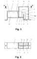
- FIGS. 1 to 4 and 12 and 13 show a first basic variant and in FIGS. 5 to 11 a second basic variant of the device according to the invention for evaporating liquid.
- the device consists of an essentially cuboid-shaped container which is divided by a vertical central wall 2 into two container parts which have a common bottom surface.
- the first container part is closed on all sides and serves as storage space 1 for the evaporation liquid 10.
- the second container part is stepped from the first container part and is a dosing space 4 for the evaporation liquid 10.
- the storage space 1 and the dosing space 4 are connected to one another via a gap-shaped passage opening 3 connected, whereby a constant liquid level 8 is generated in the dosing chamber 4, which is independent of the liquid level 7 in the storage room 1. How this liquid level 8 is formed in detail has already been explained in the introductory statements to DD 292 141 B 5.
- a third container part which serves as an evaporation space 5, adjoins the second container part in the longitudinal direction.
- This evaporation space 5 is spatially separated from the dosing space 4 by means of a continuous transverse wall 6.
- the bottom surface of the evaporation chamber 5 is substantially lower than the bottom surface of the storage chamber 1 or the dosing chamber 4.
- a longitudinal wall 14 is arranged in the evaporation chamber 5, which extends from the middle wall 2 to the right side wall of the evaporation chamber 5. According to one embodiment, the left part of this longitudinal wall 14 is guided continuously to the bottom surface of the metering chamber 4, the length of the passage opening 3 being limited by the longitudinal wall 14. According to another embodiment, however, the left part of the longitudinal wall 14 has a slit-shaped opening at the bottom and the passage opening 3 extends over the entire width of the container.
- a first evaporation element 13 is arranged vertically in front of the longitudinal wall 14, and a second evaporation element 11 is aligned with it. This second evaporation element 11 is provided with a rectangular cutout 20, so that there is an unequal leg U-shape.
- a third evaporation element 12 is arranged vertically behind the longitudinal wall 14, which has essentially the same U-shape as the second evaporation element 11 and whose longer leg rests on the bottom surface of the evaporation space 5.
- the shorter leg of the third evaporation element 12 must be dimensioned so short that it does not fall into the liquid level 8 of the dosing space when the container is tilted, for example during transport 4 dips.
- the longer leg of the third evaporation element 12 is configured at right angles. The angled leg part rests on the bottom surface of the evaporation space 5 and is guided up to below the longer leg of the second evaporation element 11. The longer leg of the second evaporation element 11 must be shortened so that the two evaporation elements 11 and 12 do not touch. In the first embodiment shown in FIGS.
- the dosing chamber 4 and the evaporation chamber 5 are covered at the top by a protective hood 15.
- This protective hood 15 is detachably connected to the container housing, which is expediently carried out via latching and clamping elements.
- the protective hood 15 has a plurality of openings, the number of which is dimensioned such that a maximum amount of evaporated liquid can pass through. The dimensions of these openings are designed so that direct contact of the bees with the evaporation elements 11, 12, 13 is prevented.
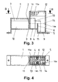
- the protective hood 15 is open at the top and otherwise has no additional openings.
- vertical ribs 15a are provided which are arranged at a distance of approximately 3.5 mm. These ribs 15a are located in the space between the front or rear longitudinal wall of the metering and evaporation chamber 4 and 5 and the front or rear wall of the protective hood 15 and the evaporation elements 13, 11 and 12. These ribs 15a can either only in the area the protective hood 15 may be provided or extend vertically from the bottom surface of the dosing and evaporation chamber 4 and 5 up to the upper edge of the protective hood 15.
- the ribs 15a can expediently be designed as a one-piece spacer element 14b which is inserted into the aforementioned intermediate space. But it is also possible that they are formed as part of the front and rear walls of the dosing and evaporation space 4 and 5 and the protective hood 15 or are only provided on the protective hood 15.
- the sixth embodiment according to FIGS. 12 and 13 differs from the first embodiment (FIGS. 1 and 2) in that the second evaporation element 11 consists of two L-shaped individual elements, the short legs of which overlap in a certain area and which are horizontal are movable.
- the fact that one leg runs at a right angle and the other leg slopes, the cross section of the second evaporation element 11 is adjustable.
- the external dimensions of the device are adapted to the requirements of conventional beehives in such a way that it can be fastened in a honeycomb frame 25 and can be fitted in the bee house instead of a honeycomb. In any case, the width of the device is not greater than the width of a honeycomb frame 25.
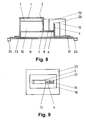
- the second basic variant shown in FIGS. 5 to 11 differs from the first basic variant in that no spatially limited evaporation space 5 is provided, the lower part of the transverse wall 6 is connected to a horizontal spacer plate 17 and the third evaporation element 16 horizontally under the spacer plate 17 and the Container is arranged.
- the spacer plate 17 is also substantially lower than the common bottom surface of the storage or dosing space 1 and 4.
- the spacer plate 17 is provided with sieve-like openings for the passage of liquid at least in the region of the longer leg.
- the area of the third evaporation element 16 is larger than the area of the device.
- a cover is also provided under the third evaporation element 16, which in turn is larger than the area of the third evaporation element 16.
- this cover consists of an acid-resistant plastic film 18 with gauze 19 arranged underneath.
- the cover consists of an acid-resistant partition plate 23, which is provided with feet 24.
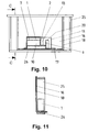
- the cover of the fifth embodiment shown in FIGS. 10 and 11 consists only of the separating film 18.
- a height adjustment device 21 can be provided on the left side wall of the storage room 1, which makes it possible to tilt the device, whereby the liquid level 8 in the metering chamber 4 for the evaporation element 13 can be reduced.
- the embodiments shown in FIGS. 5 to 9 are preferably used when the regulating influence of the shrunken brood nest has become very small in late season and interventions in the honeycomb structure are to be avoided, but it is desirable because of possible reinfection from the neighborhood, which postpone last treatment of the current year.
- the device is arranged in a bee-free room, preferably above the apiary.
- the fifth embodiment is for use in FIG so-called after-treatment hives between the window and the latter Honeycomb provided.
- the device is on the bottom Leg (26) attached to a honeycomb frame 25, which third evaporation element 16 and the plastic film 18 one long side approximately flush with the leg 26 of the honeycomb frame Complete 25 and this on the opposite Long side angled and led vertically upwards are.
- the plastic film 18 is analogous to the first embodiment also openings.
Abstract
Description
Die Erfindung betrifft ein Verfahren und eine Vorrichtung zum Verdunsten von Flüssigkeiten, insbesondere von Ameisensäure zur Bekämpfung von Varroamilben in Bienenwohnungen.The invention relates to a method and an apparatus for Evaporation of liquids, especially formic acid to combat varroa mites in apiaries.
Der Begriff "Verdunstung" wird in den folgenden Darlegungen im Sinne eines langsamen Überganges einer Flüssigkeit in den gasförmigen Zustand bei weit unterhalb des Siedepunktes der Verdunstungsflüssigkeit liegenden Temperaturen verwendet.The term "evaporation" is used in the following statements in Meaning a slow transition of a liquid into the gaseous Condition at far below the boiling point of the evaporative liquid lying temperatures used.
Aus der DD 292 141 B5 ist bereits eine Vorrichtung zum Verdunsten
von Flüssigkeiten, insbesondere von Ameisensäure bekannt,
die aus einem im wesentlichen quaderförmigen Behälter besteht,
der durch eine vertikale Mittelwand in zwei Behälterteile
unterteilt ist. Dabei ist der erste Behälterteil als allseitig
geschlossener Vorratsraum zur Aufnahme der Verdunstungsflüssigkeit
ausgelegt. Der zweite Behälterteil ist stufenförmig
abgesetzt und zur Aufnahme eines plattenförmigen Verdunstungselementes
vorgesehen, das über einen Schlitz in einem Deckel
in vertikaler Lage positioniert ist und dessen untere Stirnfläche
auf der Bodenfläche aufliegt. Im unteren Teil der vertikalen
Mittelwand ist eine spaltförmige Durchlaßöffnung ausgebildet,
die eine Verbindung in Nähe der gemeinsamen Bodenfläche
zwischen beiden Behälterteilen herstellt.
Die Wirkungsweise dieser bekannten Vorrichtung besteht darin,
daß die Verdunstungsflüssigkeit aus dem Vorratsraum über die
Durchlaßöffnung in den zweiten Behälterteil fließt und dort
nur so hoch aufsteigt, bis die Flüssigkeit die Durchlaßöffnung
verschließt. Ursache dafür ist, daß sich beim Abfließen der
Flüssigkeit aus dem Vorratsraum ein Unterdruck ausbildet, der
das weitere Ansteigen der Verdunstungsflüssigkeit im zweiten
Behälterteil verhindert. Wird nun Verdunstungsflüssigkeit über
das Verdunstungselement abgeführt, sinkt das Flüssigkeitsniveau
im zweiten Behälterteil etwas, und es wird Luft in Form
kleiner Luftblasen in den Vorratsraum eingesogen und der Unterdruck
ausgeglichen, so daß wieder Flüssigkeit in den zweiten
Behälterteil nachfließen kann. Diese steigt dann an, bis
die Durchlaßöffnung wieder verschlossen ist, wodurch die Luftzufuhr
unterbrochen wird. Auf diese Weise wird ein annähernd
konstantes Flüssigkeitsniveau im zweiten Behälterteil erzielt,
wodurch ein gleichmäßiger Förderstrom im Verdunstungselement
gewährleistet wird, der vom unterschiedlichen Füllstand im
Vorratsraum unabhängig ist.From DD 292 141 B5 a device for evaporating liquids, in particular formic acid, is already known which consists of an essentially cuboid-shaped container which is divided into two container parts by a vertical central wall. The first container part is designed as a storage space that is closed on all sides for receiving the evaporation liquid. The second container part is stepped and provided for receiving a plate-shaped evaporation element, which is positioned in a vertical position via a slot in a lid and whose lower end face rests on the bottom surface. In the lower part of the vertical central wall, a gap-shaped passage opening is formed, which creates a connection in the vicinity of the common bottom surface between the two container parts.
The mode of operation of this known device is that the evaporation liquid flows from the storage space through the passage opening into the second container part and rises there only until the liquid closes the passage opening. The reason for this is that when the liquid flows out of the storage space, a negative pressure is formed, which prevents the evaporation liquid from rising further in the second container part. If evaporation liquid is now removed via the evaporation element, the liquid level in the second container part drops somewhat, and air in the form of small air bubbles is sucked into the storage space and the negative pressure is equalized, so that liquid can flow into the second container part again. This then increases until the passage opening is closed again, whereby the air supply is interrupted. In this way, an approximately constant liquid level is achieved in the second container part, which ensures a uniform flow in the evaporation element, which is independent of the different fill level in the storage space.
Bekanntlich ist die Verdunstung einer Flüssigkeit von vielen
Parametern abhängig. Wesentliche Einflußfaktoren sind die
Größe, Form und Porosität der Oberfläche des Verdunstungselementes,
der Luftdruck, die Luftfeuchtigkeit und die Luftzirkulation
sowie die Temperatur.
Der Nachteil der bekannten Vorrichtung besteht darin, daß die
abgegebene Verdunstungsrate (also Verdunstungsmenge pro Zeiteinheit)
durch die Abhängigkeit von einem Teil der vorgenannten
Umgebungsbedingungen, nämlich Luftdruck, Luftfeuchtigkeit,
Luftzirkulation und Temperatur höchst unterschiedlich ist.
Hinzu kommt, daß die Bekämpfung von Varroamilben mehrmals im
Jahr und zu unterschiedlichen Jahreszeiten durchgeführt werden
muß. In Deutschland erfolgt dieses erstmalig im Sommer, etwa
August nach der letzten Honigernte und im Herbst, ca. September/Oktober.
Daraus folgt, daß zum Zeitpunkt der Bekämpfung
stets unterschiedliche äußere Umgebungsbedingungen vorliegen.
Entscheidend für eine wirksame Bekämpfung ist jedoch eine
ausreichende Konzentration von Ameisensäure in der Verdunstungsluft
der Bienenwohnung. In Deutschland bestehen diesbezüglich
Vorgaben für die Mindest- bzw. Höchstverdunstungsrate
bezogen auf die Umgebungstemperatur, die im Herbst bei ca. 15
bis 20 °C etwa 10 ml/Tag und im Sommer bei ca. 25 bis 30 °C
etwa 25 ml/Tag beträgt. Auch die Umgebungsbedingungen im Inneren
der Bienenwohnung sind keinesfalls konstant.
Die Bienen versuchen innen immer eine gleichbleibende Temperatur
zu halten, im Brutnest beispielsweise +35 °C. Bei höheren
Außentemperaturen oder direkter Sonneneinstahlung wird die
Luft in der Bienenwohnung dadurch gekühlt, daß eine bestimmte
Anzahl von Bienen durch ihre Flügelbewegung, dem sogenannten
"fächeln" einen gerichteten Luftstrom erzeugen, der durch eine
Öffnung nach außen geleitet wird, während frische Luft in die
Bienenwohnung nachströmt. Es ist also eine erhöhte Luftwechselrate
zu verzeichnen, die die Konzentration von Ameisensäure
in der Bienenwohnung herabsetzt.
Um die Nachteile der bekannten Vorrichtung zu kompensieren,
hat man bisher für unterschiedliche Umgebungsbedingungen verschieden
große Verdunstungselemente eingesetzt und zur Optimierung
der Verdunstungsmenge Kontrollen während der Behandlung
empfohlen. Diese Maßnahmen sind nicht nur kostenintensiv,
sondern auch sehr aufwendig.
Ein weiterer Nachteil der bekannten Vorrichtung ist auch, daß
die verdunstete Flüssigkeitsmenge in der Anfangsphase der
Behandlung schnell ansteigt. Dieses hat zur Folge, daß Streß
und Aggressivität der Bienen zunehmen, die das Leben der Königin
gefährden können.As is well known, the evaporation of a liquid depends on many parameters. The main influencing factors are the size, shape and porosity of the surface of the evaporation element, the air pressure, the air humidity and the air circulation as well as the temperature.
The disadvantage of the known device is that the evaporation rate given (ie the amount of evaporation per unit of time) is very different due to the dependence on a part of the above-mentioned environmental conditions, namely air pressure, air humidity, air circulation and temperature. In addition, varroa mites must be combated several times a year and at different times of the year. In Germany, this takes place for the first time in summer, around August after the last honey harvest and in autumn, around September / October. It follows that there are always different external environmental conditions at the time of the control. However, a sufficient concentration of formic acid in the evaporative air of the apiary is crucial for effective control. In Germany, there are guidelines for the minimum or maximum evaporation rate based on the ambient temperature, which is approximately 10 ml / day in autumn at approx. 15 to 20 ° C and approx. 25 ml / day in summer at approx. 25 to 30 ° C . The environmental conditions inside the apiary are by no means constant.
The bees always try to keep a constant temperature inside, for example +35 ° C in the brood nest. At higher outside temperatures or in direct sunlight, the air in the apiary is cooled by the fact that a certain number of bees generate a directed air flow through their wing movement, the so-called "fanning", which is directed outside through an opening, while fresh air enters the apiary flows. So there is an increased air exchange rate, which reduces the concentration of formic acid in the apiary.
In order to compensate for the disadvantages of the known device, evaporation elements of different sizes have hitherto been used for different environmental conditions and controls during treatment have been recommended to optimize the amount of evaporation. These measures are not only cost-intensive, but also very complex.
Another disadvantage of the known device is that the amount of liquid evaporated increases rapidly in the initial phase of the treatment. As a result, the bees' stress and aggressiveness increase, which can endanger the life of the queen.
Aufgabe der vorliegenden Erfindung ist es, ein Verfahren und
eine verbesserte Vorrichtung nach dem Oberbegriff der Patentansprüche
1, 2 und 3 zu schaffen, mit denen die Einflüsse der
unterschiedlichen Umgebungsbedingungen auf das Verdunstungsverhalten
reduziert werden, der jahreszeitliche Anwendungsbereich
ohne Verwendung unterschiedlicher Größen von Verdunstungselementen
erhöht und ein sehr langsamer Anstieg der
Verdunstung in der Anfangsphase erzielt wird.The object of the present invention is a method and
an improved device according to the preamble of the
Diese Aufgabe wird durch die im Kennzeichen der Ansprüche 1,
2 und 3 genannten Merkmale gelöst. Zweckmäßige Ausgestaltungen
der Vorrichtung sind in den Ansprüchen 4 bis 22 offenbart.This object is achieved by the
2 and 3 mentioned features solved. Appropriate configurations
of the device are disclosed in
Die mit der Erfindung erzielten Vorteile werden wie folgt
begründet:
Bei bekannten Verdunstern mit nur einem, in die Verdunstungsflüssigkeit
eines Behälters eintauchenden Verdunstungselement
wurde experimentell ermittelt, daß die Förderrate (also Flüssigkeitsmenge
pro Zeiteinheit) bei einem vollständig gefüllten
Behälter gegenüber einem fast entleerten Behälter erheblich
unterschiedlich ist. Durch diese Abhängigkeit vom Flüssigkeitsniveau
im Behälter ist neben den Umgebungsbedingungen
eine weitere Einflußgröße auf das Verdunstungsverhalten gegeben.
Diese Einflußgröße wird durch die Ausbildung des Vorratsraumes
in Verbindung mit der spaltförmigen Durchlaßöffnung
dahingehend eleminiert, daß im Dosierraum ein konstantes Niveau
von Verdunstungsflüssigkeit erzeugt wird, in dem das
Verdunstungselement stets gleich tief eingetaucht ist. Durch
die Verwendung von zwei Verdunstungselementen, die aus dem
Dosierraum mit Verdunstungsflüssigkeit versorgt werden, wird
der Hauptkapillarstrom in zwei Teilkapillarströme aufgeteilt.
Der erste Teilkapillarstrom steigt über das erste Verdunstungselement
vertikal nach oben und verdunstet entsprechend
der gegebenen Umgebungsbedingungen. Beispielsweise wird bei
höherer Temperatur oder Luftzirkulation mehr Flüssigkeit verdunstet
als bei niedrigerer Temperatur oder Luftzirkulation.
Da das erste Verdunstungselement im unmittelbaren Kontakt mit
dem Flüssigkeitsniveau im Dosierraum steht, wird es entsprechend
der bereits verdunsteten Flüssigkeitsmenge stets weitere
Verdunstungsflüssigkeit nachziehen. Die Flüssigkeitsmenge pro
Zeiteinheit des ersten Teilkapillarstromes verändert sich also
in Abhängigkeit von den Umgebungsbedingungen. Durch die U-förmige
Ausbildung des zweiten Verdunstungselementes wird der
zweite Teilkapillarstrom durch die Einwirkung der Kapillarität
und Schwerkraft in einen tiefer liegenden Verdunstungsraum
umgeleitet, wo die Flüssigkeit vom längeren Schenkel auf ein
drittes Verdunstungselement abtropft bzw. an dieses Element
abgegeben wird. Dabei entsteht ein feuchter Fleck aus Verdunstungsflüssigkeit.
Da aber das dritte Verdunstungselement vom
zweiten Verdunstungselement in einem solchen Abstand angeordnet
ist, der eine gegenseitige Berührung beider Elemente ausschließt,
kann bei einer Verdunstung des Flüssigkeitsfleckes
im Gegensatz zum ersten Verdunstungselement keine weitere
Flüssigkeit nachgesaugt werden. Der zweite Teilkapillarstrom
ist also konstant und von den Umgebungsbedingungen unabhängig,
insbesondere dann, wenn das zweite Verdunstungselement mit
einer zusätzlichen Beschichtung oder Abdeckung versehen ist.
Die Größe des Flüssigkeitsfleckes auf dem dritten Verdunstungselement
wird damit ausschließlich vom abtropfenden Flüssigkeitsstrom
bestimmt. Setzt nun die Verdunstung des Flüssigkeitsfleckes
entsprechend der gegebenen Umgebungsbedingungen
ein, verringert sich dessen wirksame Verdunstungsfläche bis
wieder neue Flüssigkeit abtropft. Bei entsprechender Auslegung
des zweiten Verdunstungselementes ist es möglich, daß der
Flüssigkeitsfleck völlig verdunstet, bevor wieder neue Flüssigkeit
abtropft.
Da sich der Flüssigkeitsfleck auf dem dritten Verdunstungselement
nur verzögert und gegebenenfalls in bestimmten Zeitintervallen
ausbilden kann, wird insgesamt nur ein langsamer
Anstieg der Verdunstung in der Anfangsphase erreicht.
Die Wirkungen des ersten Verdunstungselementes und die Wirkungen
des zweiten und dritten Verdunstungselementes ergänzen
sich so, daß die Einflüsse der Umgebungsbedingungen reduziert
werden und sich der jahreszeitliche Anwendungsbereich ohne
Verwendung unterschiedlicher Größen von Verdunstungselementen
erhöht.The advantages achieved with the invention are justified as follows:
In known evaporators with only one evaporation element immersed in the evaporation liquid of a container, it was experimentally determined that the delivery rate (that is, the quantity of liquid per unit of time) in a completely filled container is considerably different than in an almost empty container. This dependency on the liquid level in the container, in addition to the ambient conditions, gives a further influence on the evaporation behavior. This influencing variable is eliminated by the design of the storage space in connection with the slit-shaped passage opening in such a way that a constant level of evaporation liquid is generated in the dosing space, in which the evaporation element is always immersed to the same depth. By using two evaporation elements, which are supplied with evaporation liquid from the dosing chamber, the main capillary flow is divided into two partial capillary flows. The first partial capillary flow rises vertically above the first evaporation element and evaporates according to the given environmental conditions. For example, more liquid is evaporated at a higher temperature or air circulation than at a lower temperature or air circulation. Since the first evaporation element is in direct contact with the liquid level in the dosing chamber, it will always draw in further evaporation liquid in accordance with the amount of liquid that has already evaporated. The amount of liquid per unit time of the first partial capillary flow therefore changes depending on the ambient conditions. Due to the U-shaped design of the second evaporation element, the second partial capillary flow is diverted by the action of capillarity and gravity into a lower-lying evaporation space, where the liquid drips from the longer leg onto a third evaporation element or is released to this element. This creates a damp patch of evaporation liquid. However, since the third evaporation element is arranged at such a distance from the second evaporation element that prevents the two elements from touching each other, in contrast to the first evaporation element, no further liquid can be drawn in when the liquid stain evaporates. The second partial capillary flow is therefore constant and independent of the ambient conditions, in particular when the second evaporation element is provided with an additional coating or cover. The size of the liquid spot on the third evaporation element is thus determined exclusively by the dripping liquid stream. If the evaporation of the liquid stain commences in accordance with the given ambient conditions, its effective evaporation area is reduced until new liquid drips off again. With an appropriate design of the second evaporation element, it is possible for the liquid stain to evaporate completely before new liquid drips off again.
Since the liquid stain on the third evaporation element can only be delayed and possibly form at certain time intervals, overall only a slow increase in evaporation is achieved in the initial phase. The effects of the first evaporation element and the effects of the second and third evaporation elements complement one another in such a way that the influences of the ambient conditions are reduced and the seasonal application area increases without using different sizes of evaporation elements.
Die Erfindung soll nachstehend an mehreren Ausführungsbeispielen näher erläutert werden. In den dazugehörigen Zeichnungen zeigen:
- Fig. 1 -
- die Vorderansicht der Verdunstungsvorrichtung gemäß einer ersten Ausführungsform im Schnitt;
- Fig. 2 -
- den Schnitt A - A gemäß Fig. 1;
- Fig. 3 -
- die Vorderansicht der Verdunstungsvorrichtung gemäß einer zweiten Ausführungsform im Schnitt;
- Fig. 4 -
- den Schnitt B - B gemäß Fig. 3;
- Fig. 5 -
- die Vorderansicht der Verdunstungseinrichtung gemäß einer dritten Ausführungsform im Schnitt;
- Fig. 6 -
- die Verdunstungsvorrichtung in Draufsicht nach Fig. 5;
- Fig. 7 -
- die Vorderansicht nach Fig. 5 in gekippter Lage;
- Fig. 8 -
- die Vorderansicht der Verdunstungsvorrichtung gemäß einer vierten Ausführungsform im Schnitt;
- Fig. 9 -
- die Verdunstungsvorrichtung in Draufsicht nach Fig. 8;
- Fig. 10 -
- die Vorderansicht der Verdunstungsvorrichtung gemäß einer fünften Ausführungsform teilweise im Schnitt;
- Fig. 11 -
- den Schnitt C - C gemäß Fig. 10;
- Fig. 12 -
- die Vorderansicht der Verdunstungsvorrichtung gemäß einer sechsten Ausführungsform im Schnitt;
- Fig. 13 -
- den Schnitt D - D gemäß Fig. 12.
- Fig. 1 -
- the front view of the evaporation device according to a first embodiment in section;
- Fig. 2 -
- the section A - A of FIG. 1;
- Fig. 3 -
- the front view of the evaporation device according to a second embodiment in section;
- Fig. 4 -
- the section BB according to FIG. 3;
- Fig. 5 -
- the front view of the evaporation device according to a third embodiment in section;
- Fig. 6 -
- the evaporation device in plan view of FIG. 5;
- Fig. 7 -
- the front view of Figure 5 in a tilted position.
- Fig. 8 -
- the front view of the evaporation device according to a fourth embodiment in section;
- Fig. 9 -
- the evaporation device in plan view of FIG. 8;
- Fig. 10 -
- the front view of the evaporation device according to a fifth embodiment, partly in section;
- Fig. 11 -
- the section C - C of FIG. 10;
- Fig. 12 -
- the front view of the evaporation device according to a sixth embodiment in section;
- Fig. 13 -
- the section D - D according to FIG. 12.
In Fig. 1 bis 4 sowie 12 und 13 ist eine erste Grundvariante
und in Fig. 5 bis 11 eine zweite Grundvariante der erfindungsgemäßen
Vorrichtung zum Verdunsten von Flüssigkeit dargestellt.
Wie aus Fig. 1 bis 13 ersichtlich ist, besteht die
Vorrichtung aus einem im wesentlichen quaderförmigen Behälter,
der durch eine vertikale Mittelwand 2 in zwei Behälterteile
unterteilt ist, die eine gemeinsame Bodenfläche aufweisen. Der
erste Behälterteil ist allseitig geschlossen ausgebildet und
dient als Vorratsraum 1 für die Verdunstungsflüssigkeit 10.
Der zweite Behälterteil ist zum ersten Behälterteil stufenförmig
abgesetzt und ist ein Dosierraum 4 für die Verdunstungsflüssigkeit
10. Der Vorratsraum 1 und der Dosierraum 4 sind
über eine spaltförmige Durchlaßöffnung 3 miteinander verbunden,
wodurch im Dosierraum 4 ein konstantes Flüssigkeitsniveau
8 erzeugt wird, das vom Flüssigkeitsniveau 7 im Vorratsraum 1
unabhängig ist. Wie sich dieses Flüssigkeitsniveau 8 im einzelnen
ausbildet, wurde bereits in den einleitenden Darlegungen
zur DD 292 141 B 5 erläutert.
Gemäß der in Fig. 1 bis 4 sowie 12 und 13 dargelegten ersten
Grundvariante schließt sich in Längsrichtung an den zweiten
Behälterteil ein dritter Behälterteil an, der als Verdunstungsraum
5 dient. Dieser Verdunstungsraum 5 ist mittels
einer durchgehenden Querwand 6 vom Dosierraum 4 räumlich getrennt.
Dabei liegt die Bodenfläche des Verdunstungsraumes 5
wesentlich tiefer als die Bodenfläche des Vorratsraumes 1 bzw.
des Dosierraumes 4. Im Verdunstungsraum 5 ist eine Längswand
14 angeordnet, die sich von der Mittelwand 2 bis zur rechten
Seitenwand des Verdunstungsraumes 5 erstreckt. Nach einer
Ausführungsform ist der linke Teil dieser Längswand 14 durchgehend
bis zur Bodenfläche des Dosierraumes 4 geführt, wobei
die Länge der Durchlaßöffnung 3 durch die Längswand 14 begrenzt
ist. Nach einer anderen Ausführungsform weist der linke
Teil der Längswand 14 dagegen unten eine spaltförmige Öffnung
auf und die Durchlaßöffnung 3 erstreckt sich über die gesamte
Breite des Behälters. Vor der Längswand 14 ist ein erstes
Verdunstungselement 13 und fluchtend daneben ein zweites Verdunstungselement
11 senkrecht angeordnet. Dieses zweite Verdunstungselement
11 ist mit einem rechteckigen Ausschnitt 20
versehen, so daß sich eine ungleichschenklige U-Form ergibt.
Dabei ist der linke, sich auf der Bodenfläche des Dosierraumes
4 abstützende Schenkel wesentlich kürzer als der rechte Schenkel.
Dieser rechte Schenkel muß nicht auf der Bodenfläche des
Verdunstungsraumes 5 aufliegen; er kann auch kürzer ausgebildet
sein, insbesondere dann, wenn man ein Abtropfen der Verdunstungsflüssigkeit
10 erzielen will. In weiterer Ausbildung
der Erfindung ist hinter der Längswand 14 ein drittes Verdunstungselement
12 senkrecht angeordnet, das im wesentlichen die
gleiche U-Form wie das zweite Verdunstungselement 11 aufweist
und dessen längerer Schenkel auf der Bodenfläche des Verdunstungsraumes
5 aufliegt. In Anpassung an die Ausführungsform,
bei der der linke Teil der Längswand 14 unten eine spaltförmige
Öffnung besitzt, muß der kürzere Schenkel des dritten Verdunstungselementes
12 so kurz bemessen werden, daß er beim
Kippen des Behälters, beispielsweise beim Transport nicht in
das Flüssigkeitsniveau 8 des Dosierraumes 4 eintaucht. Nach
einer zweckmäßigen Ausgestaltung dieser ersten Grundvariante
ist der längere Schenkel des dritten Verdunstungselementes 12
rechtwinklig ausgestaltet. Dabei liegt der abgewinkelte Schenkelteil
auf der Bodenfläche des Verdunstungsraumes 5 auf und
ist bis unter den längeren Schenkel des zweiten Verdunstungselementes
11 geführt. Dabei muß der längere Schenkel des zweiten
Verdunstungselementes 11 so verkürzt werden, daß sich die
beiden Verdunstungselemente 11 und 12 nicht berühren.
Bei der in Fig. 1 und 2 gezeigten ersten Ausführungsform ist
der Dosierraum 4 und der Verdunstungsraum 5 oben durch eine
Schutzhaube 15 abgedeckt. Diese Schutzhaube 15 ist lösbar mit
dem Behältergehäuse verbunden, was zweckmäßigerweise über
Rast- und Klemmelemente erfolgt. Die Schutzhaube 15 weist
mehrere Öffnungen auf, deren Anzahl so bemessen ist, daß eine
maximale Menge von verdunsteter Flüssigkeit hindurchtreten
kann. Die Abmessungen dieser Öffnungen sind so ausgelegt, daß
ein unmittelbarer Kontakt der Bienen mit den Verdunstungselementen
11, 12, 13 verhindert wird.
Bei der zweiten Ausführungsform (Fig. 3 und 4) ist die Schutzhaube
15 oben offen und besitzt ansonsten keine zusätzlichen
Öffnungen. Um einerseits einen Berührungsschutz und andererseits
eine bessere Positionierung der Verdunstungselemente 11,
12, 13 zu ermöglichen, sind vertikale Rippen 15a vorgesehen,
die in einem Abstand von ca. 3,5 mm angeordnet sind. Diese
Rippen 15a befinden sich im Zwischenraum zwischen der vorderen
bzw. hinteren Längswand des Dosier- und Verdunstungsraumes 4
und 5 sowie der Vorder- bzw. Hinterwand der Schutzhaube 15 und
den Verdunstungselementen 13, 11 bzw. 12. Diese Rippen 15a
können entweder nur im Bereich der Schutzhaube 15 vorgesehen
sein oder durchgehend von der Bodenfläche des Dosier- und
Verdunstungsraumes 4 und 5 vertikal bis zur Oberkante der
Schutzhaube 15 verlaufen. Die Rippen 15a können zweckmäßigerweise
als einstückiges Distanzelement 14b ausgebildet sein,
das in den vorgenannten Zwischenraum eingeschoben wird. Es ist
aber auch möglich, daß sie als Bestandteil der Vorder- und
Hinterwände des Dosier- und Verdunstungsraumes 4 und 5 und der
Schutzhaube 15 ausgeformt sind oder nur an der Schutzhaube 15
vorgesehen sind.1 to 4 and 12 and 13 show a first basic variant and in FIGS. 5 to 11 a second basic variant of the device according to the invention for evaporating liquid. As can be seen from FIGS. 1 to 13, the device consists of an essentially cuboid-shaped container which is divided by a vertical
According to the first basic variant set out in FIGS. 1 to 4 and 12 and 13, a third container part, which serves as an
In the second embodiment (FIGS. 3 and 4), the
Die sechste Ausführungsform gemäß Fig. 12 und 13 unterscheidet
sich von der ersten Ausführungsform (Fig. 1 und 2) dadurch,
daß das zweite Verdunstungselement 11 aus zwei L-förmigen
Einzelelementen besteht, deren kurze Schenkel sich in in einem
gewissen Bereich überlappen und die horizontal verschiebbar
sind. Dadurch, daß der eine Schenkel rechtwinklig und der
andere Schenkel schräg ausläuft, ist der Querschnitt des zweiten
Verdunstungselementes 11 einstellbar. Die äußeren Abmessungen
der Vorrichtung sind so an die Erfordernisse üblicher
Bienenwohnungen angepaßt, daß sie in einem Wabenleerrähmchen
25 befestigt und anstelle einer Wabe in der Bienenwohnung
angebracht werden kann. In jedem Fall ist die Breite der Vorrichtung
nicht größer als die Breite eines Wabenrähmchens 25.
Da die von den Bienen konstant gehaltene Brutnesttemperatur
einerseits zur Verdunstung beiträgt, andererseits aber ein
unmittelbarer Kontakt zum Brutnest Brutschäden verursachen
kann, wird die Vorrichtung vorrangig in der ersten brutfreien
Wabengasse angeordnet.
Die in Fig. 5 bis 11 gezeigte zweite Grundvariante unterscheidet
sich von der ersten Grundvariante dadurch, daß kein räumlich
begrenzter Verdunstungsraum 5 vorgesehen, der untere Teil
der Querwand 6 mit einer waagerechten Distanzplatte 17 verbunden
und das dritte Verdunstungselement 16 waagerecht unter
der Distanzplatte 17 und dem Behälter angeordnet ist. Dabei
liegt die Distanzplatte 17 ebenfalls wesentlich tiefer als die
gemeinsame Bodenfläche des Vorrats- bzw. Dosierraumes 1 und 4.
Die Distanzplatte 17 ist mindestens im Bereich des längeren
Schenkels mit siebartigen Öffnungen für den Flüssigkeitsdurchtritt
versehen. Die Fläche des dritten Verdunstungselementes
16 ist größer als die Grundfläche der Vorrichtung. Unter dem
dritten Verdunstungselement 16 ist weiterhin eine Abdeckung
vorgesehen, die wiederum größer als die Fläche des dritten
Verdunstungselementes 16 ist. The sixth embodiment according to FIGS. 12 and 13 differs from the first embodiment (FIGS. 1 and 2) in that the
The second basic variant shown in FIGS. 5 to 11 differs from the first basic variant in that no spatially
Bei der dritten Ausführungsform gemäß Fig. 5, 6 und 7 besteht
diese Abdeckung aus einer säureresistenten Kunststoffolie 18
mit darunter angeordneter Gaze 19.
Bei der vierten Ausführungsform gemäß Fig. 8 und 9 besteht die
Abdeckung hingegen aus einer säureresistenten Trennplatte 23,
die mit Füßen 24 versehen ist.In the third embodiment according to FIGS. 5, 6 and 7, this cover consists of an acid-
In the fourth embodiment according to FIGS. 8 and 9, however, the cover consists of an acid-
Die Abdeckung der fünften Ausführungsform gemäß Fig. 10 und 11
besteht nur aus der Trennfolie 18.The cover of the fifth embodiment shown in FIGS. 10 and 11
consists only of the separating
Aus Fig. 7 ist ersichtlich, daß an der linken Seitenwand des
Vorratsraumes 1 eine Höhenverstelleinrichtung 21 vorgesehen
sein kann, die es ermöglicht, die Vorrichtung zu kippen, wodurch
das Flüssigkeitsniveau 8 im Dosierraum 4 für das Verdunstungselement
13 reduziert werden kann.
Die in Fig. 5 bis 9 gezeigten Ausführungsformen werden vorzugsweise
dann verwendet, wenn in fortgeschrittener Jahreszeit
der regulierende Einfluß des geschrumpften Brutnestes sehr
gering geworden ist und Eingriffe in die Wabenordnung vermieden
werden sollen, es aber andererseits wegen möglicher Reinfektion
aus der Nachbarschaft wünschenswert ist, die letzte
Behandlung des laufenden Jahres hinauszuschieben. Dabei wird
die Vorrichtung in einem bienenfreien Raum, vorzugsweise oberhalb
der Bienenwohnung angeordnet.From Fig. 7 it can be seen that a
The embodiments shown in FIGS. 5 to 9 are preferably used when the regulating influence of the shrunken brood nest has become very small in late season and interventions in the honeycomb structure are to be avoided, but it is desirable because of possible reinfection from the neighborhood, which postpone last treatment of the current year. The device is arranged in a bee-free room, preferably above the apiary.
Hingegen ist die fünfte Ausführungsform für die Verwendung in
sogenannten Hinterbehandlungsbeuten zwischen Fenster und letzter
Wabe vorgesehen. Dazu ist die Vorrichtung auf dem unteren
Schenkel (26) eines Wabenleerrähmchens 25 befestigt, wobei das
dritte Verdunstungselement 16 und die Kunststoffolie 18 an
einer Längsseite etwa bündig mit dem Schenkel 26 des Wabenleerrähmchens
25 abschließen und diese an der gegenüberliegenden
Längsseite abgewinkelt und vertikal nach oben geführt
sind. Die Kunststoffolie 18 weist analog zur ersten Ausführungsform
ebenfalls Öffnungen auf. In contrast, the fifth embodiment is for use in FIG
so-called after-treatment hives between the window and the latter
Honeycomb provided. The device is on the bottom
Leg (26) attached to a
Es hat sich für alle Ausführungsformen als sehr vorteilhaft
erwiesen, wenn die Oberfläche des zweiten Verdunstungselementes
11 mit Ausnahme der Schenkelstirnflächen mit einer für die
Verdunstungsflüssigkeit 10 undurchlässigen, säureresistenten
Beschichtung oder Abdeckung versehen ist, die ein Lack oder
ein Kunststoff sein kann. Diese Ausbildung verhindert ein
Verdunsten des Kapillarstromes auf seinem Wege zum längeren
Schenkel des zweiten Verdunstungselementes 11, das nunmehr nur
noch eine reine Transportfunktion für die Verdunstungsflüssigkeit
10 ausführt.It has proven to be very advantageous for all embodiments
proven when the surface of the
Claims (22)
- A process for evaporating liquids, especially formic acid for combating varroa mites in beehives, whereinanda constant level of liquid to be evaporated is produced in a container;the main capillary flow of evaporation liquid, which develops in the evaporation element submerged in the liquid for evaporation is divided into two partial capillary flows;the first partial capillary flow is directed vertically upward by the liquid evaporated;the second partial capillary flow is first directed vertically upward, then horizontally and next vertically downward into an area lower than the level of the liquid for evaporation, and a suction effect is produced there;the amount of liquid per unit of time of the first partial capillary flow is kept variable as a function of ambient conditions such as atmospheric pressure, atmospheric humidity, air circulation and temperature,the amount of liquid of the second partial capillary flow per unit of time is kept constant.
- A device for evaporating liquids, especially formic acid for combating varroa mites in beehives, comprising an essentially cubical container subdivided by a vertical middle partition (2) into two container parts lying in one horizontal plane, where the first part of the container is designed as a storage chamber (1) that is closed on all sides to accommodate the liquid (10) for evaporation, the second part of the container is designed in steps and is provided with an evaporation element (13), whose lower end face rests on the bottom surface, and the two parts of the container are connected by a slot-shaped passage (3) in the lower part of the vertical middle partition (2), wherein a third container part is connected to the second container part in the longitudinal direction as the evaporation chamber (5) which is spatially separated from the second container part by a continuous transverse partition (6), with the bottom surface of the evaporation chamber (5) being much lower than the common bottom surface of the storage chamber (1) and the second part of the container, and with a longitudinal wall (14) extending from the vertical middle partition (2) to the right side wall of the evaporation chamber (5), the left part of which, forming a dispensing chamber (4) for the liquid (10) for evaporation, continues to the bottom surface of the second part of the container, and the length of the slot-shaped passage (3) in the middle partition (2) is designed according to the width of the dispensing chamber (4), and the right part of the longitudinal wall (14) is provided with a slot-shaped opening in the lower area, the width of said slot-shaped opening being greater than the liquid level (9) in the evaporation chamber (5), and the first evaporation element (13) is arranged in front of the longitudinal wall and a second evaporation element (11) is arranged perpendicular and flush next to the former, with a U shape having legs of irregular length, with the left leg, which is supported on the bottom surface of he dispensing chamber (4) being much shorter than the right leg which is supported on the bottom surface of the evaporation chamber (5), and behind and perpendicular to the longitudinal wall (14) is arranged a third evaporation element (12), which has essentially the same shape as the second evaporation element (11) and its longer leg is also in contact with the bottom surface of the evaporation chamber (5), and all the evaporation elements (11, 12, 13) are positioned over the rib sections formed on the bottom surfaces.
- A device for evaporating liquids, especially formic acid, for combating varroa mites in beehives, comprising an essentially cube-shaped container subdivided by a vertical middle partition (2) into two container parts in one horizontal plane, with the first part of the container being designed as a storage chamber (1) that is closed on all sides to accommodate the liquid (10) for evaporation, the second part of the container being designed steps and provided with an evaporation element (13) whose lower end face rests on the bottom surface, and the two container parts are connected through a slot-shaped passage (3) in the lower part of the vertical middle partition (2), wherein the second container part is limited in the longitudinal direction by a continuous transverse partition (6), which forms a dispensing chamber (4) for the liquid (10) for evaporation, and in which a second evaporation element (11) is arranged flush next to the first evaporation element (13) and has a U shape with legs of irregular length, with the left leg which is supported on the bottom surface of the dispensing chamber (4) being much shorter than the right leg, and the bottom part of the transverse partition (6) being connected to a horizontal spacer plate (17) which is much lower than the common bottom surface of the storage chamber (1) and the dispensing chamber (4), with the longer leg of the evaporation element (11) resting on the spacer plate (17), which is provided with sieve-like openings for the liquid to pass through at least in the area of contact of the longer leg, and with a third evaporation element (16) being arranged horizontally beneath the spacer plate (17) and the container, the area of said evaporation element being larger than the base area of the container, with a cover being provided beneath the third evaporation element (16), said cover being larger in turn than the area of the third evaporation element (16).
- A device according to Claim 2, wherein the left part of the longitudinal wall (14) has a slot-shaped opening at the bottom, the length of the passage (3) in the middle partition (2) corresponds to the width of the container, and the shorter leg of the third evaporation element (12) is designed to that it does not dip into the liquid level (8) of the dispensing chamber (4) when the container is tilted, especially in transport.
- A device according to Claim 2, wherein the longer leg of the third evaporation element (12) is designed with a right-angled bend, with the bent part of the leg being arranged directly beneath the longer leg of the second evaporation element, and with the longer leg of the second evaporation element (11) being shortened so that the two evaporation elements (12) do not come in contact with one another, and the liquid (10) for evaporation can drip down from the longer leg of the second evaporation element (11).
- A device according to Claim 2, wherein the dispensing chamber (4) and the evaporation chamber (5) are covered by a protective hood (15), which is detachably connected to the container housing, preferably by catch and clamp elements, and it has openings in a number such that a maximum amount of vaporized liquid can pass through, and its dimensions are such that direct contact of the bees with the evaporation elements (11, 12, 13) is prevented.
- A device according to Claim 2, wherein vertical ribs are provided in the interspace between the front and rear longitudinal walls of the dispensing chamber (4) and evaporation chamber (5) when the dispensing and evaporation chambers (4, 5) are open at the top, and/or between the front and rear inner walls of the protective hood (15) and the evaporation elements (13, 11 and 12), said ribs extending to the top edge (14a) of the longitudinal walls of the dispensing chamber and evaporation chambers (4, 5) or to the top edge of the protective hood (15), said ribs (15a) being designed as a detachable one-piece spacer element (14b) or molded on the front and rear insides of the longitudinal walls and/or the protective hood (15).
- A device according to Claim 3, wherein the cover is an acid-resistant plastic film (18), an acid-resistant dividing plate (23) or an acid-resistant plastic film (18) with gauze (19) arranged below it, with the area of the gauze (19) being larger than the area of the plastic film (18) or the dividing plate (23).
- A device according to Claims 3 and 8 for use in back-treatment beehives, wherein the device is arranged on the lower leg (26) of an empty honeycomb frame (25), and the third evaporation element (16) under the spacer plate (17) and the container is sealed with a plastic film (18) on a longitudinal side approximately flush with the leg (26) of the empty honeycomb frame (25), said element being bent at an angle on the opposite longitudinal side and continued vertically upward, with the plastic film (18) having openings in a number such that a maximum amount of vaporized liquid can pass through and the dimensions are such that direct contact of the bees with the third evaporation element (16) is prevented.
- A device according to Claim 2 or 3, wherein the surface of the second evaporation element (11), except the end face of the leg, is provided with an acid-resistant coating or cover that is impermeable for the liquid (10) for evaporation.
- A device according to Claim 2 or 3 or 10, wherein the coating is a plastic or an enamel.
- A device according to Claim 2 or 3, wherein the cross section through the second evaporation element (11) is preferably adjustable or variable in the horizontal middle part.
- A device according to Claim 2 or 3 and 12, wherein the second evaporation element (11) consists of two individual L-shaped elements whose short legs are arranged so that they overlap in an area, and at least one individual element is horizontally displaceable, and the short leg of the one individual element runs at a right angle and that of the other individual element is at an inclination.
- A device according to Claim 2 or 3, wherein the first and second evaporation elements (13, 11) are designed in one piece.
- A device according to Claim 2 or 3, 5 as well as 10 through 14, wherein the cross-sectional area of the evaporation elements (11, 12, 13) is regular, especially triangular, rectangular, polygonal, circular, annular, sector-shaped, arc-shaped, ellipsoidal, or it may be irregular.
- A device according to Claim 2 or 3, 5 as well as 10 through 14, wherein the absorbent material of the evaporation elements (11, 12, 13, 16) is made of organic or inorganic materials or mixtures thereof.
- A device according to Claim 2 or 3, 5 as well as 10 through 14 and 16, wherein the absorbent material of the evaporation elements (11, 12, 113, 16) is paper, cardboard, ceramic, foam and a woven or nonwoven textile material such as a felt, a nonwoven or spun yarn.
- A device according to Claim 2 or 3, wherein the container is made of acid-resistant and weldable plastics, preferably polypropylene.
- A device according to Claim 2 or 3, wherein the container is designed so that it can be tilted by providing a height adjusting device (21) on the left side wall of the storage chamber (1).
- A device according to Claim 2 or 3, wherein the width of the container is not greater than the width of a honeycomb frame.
- A device according to Claim 2 or 3, wherein the container is an injection molded part which has a scale for measuring the quantity of liquid (10) to be evaporated in the storage chamber (1), preferably on the cover of the storage chamber (10, and the cover is connected to the housing of the storage chamber (1) by welding with an airtight seal.
- A device according to Claim 2 or 3, 5 as well as 10 through 14, wherein the evaporation elements (11, 12, 13) are arranged at any angle, even variably, to the vertical axis or the horizontal axis of the container.
Applications Claiming Priority (7)
| Application Number | Priority Date | Filing Date | Title |
|---|---|---|---|
| DE19610649 | 1996-03-06 | ||
| DE1996110649 DE19610649A1 (en) | 1996-03-06 | 1996-03-06 | Continuous vaporisation device for formic acid |
| DE19621149 | 1996-05-14 | ||
| DE19621149A DE19621149A1 (en) | 1996-03-06 | 1996-05-14 | Device for continuous evaporation of fluids especially formic acid in beehives |
| DE19645300 | 1996-10-25 | ||
| DE19645300A DE19645300A1 (en) | 1996-03-06 | 1996-10-25 | Evaporating formic acid to combat varroa mites infesting beehives |
| PCT/DE1997/000512 WO1997032470A1 (en) | 1996-03-06 | 1997-03-06 | Process and device for evaporating liquids, in particular formic acid |
Publications (2)
| Publication Number | Publication Date |
|---|---|
| EP0959674A1 EP0959674A1 (en) | 1999-12-01 |
| EP0959674B1 true EP0959674B1 (en) | 2000-09-27 |
Family
ID=27216041
Family Applications (1)
| Application Number | Title | Priority Date | Filing Date |
|---|---|---|---|
| EP97920509A Expired - Lifetime EP0959674B1 (en) | 1996-03-06 | 1997-03-06 | Process and device for evaporating liquids, in particular formic acid |
Country Status (4)
| Country | Link |
|---|---|
| EP (1) | EP0959674B1 (en) |
| AT (1) | ATE196589T1 (en) |
| CA (1) | CA2247051A1 (en) |
| WO (1) | WO1997032470A1 (en) |
Cited By (4)
| Publication number | Priority date | Publication date | Assignee | Title |
|---|---|---|---|---|
| DE202017100888U1 (en) | 2017-02-17 | 2017-03-02 | Joachim Weiland Werkzeugbau GmbH & Co. KG | Evaporator systems comprising a formic acid evaporator unit and a standard honeycomb blank adapted to the evaporator unit |
| DE102017103338B3 (en) | 2017-02-17 | 2018-04-05 | Joachim Meinrad Weiland | Evaporator systems comprising a formic acid evaporator unit and a standard honeycomb blank adapted to the evaporator unit |
| EP3578041A1 (en) | 2018-06-10 | 2019-12-11 | WaldWieseHolz GmbH | Dispenser for formic acid steam and method for mite combating in beehives |
| WO2021115558A1 (en) | 2019-12-09 | 2021-06-17 | Waldwieseholz Gmbh | Dispenser for formic acid vapour and method for combatting mites in beehives |
Families Citing this family (4)
| Publication number | Priority date | Publication date | Assignee | Title |
|---|---|---|---|---|
| CA2323263C (en) | 2000-10-13 | 2009-12-01 | Vaclav Ruzicka | Formic acid dispenser for control of mites |
| EP2177107A1 (en) * | 2008-10-16 | 2010-04-21 | Thomas Engel | Vermin remedy |
| DE102011000223A1 (en) | 2011-01-19 | 2012-07-19 | Acuros GmbH, Berlin | Device for releasing a volatile active substance, method for producing such a device and its use |
| TR202013201A1 (en) * | 2020-08-20 | 2022-03-21 | Ondokuz Mayis Ueniversitesi | Vaporization apparatus for formic acid used in the control of varroa mites in honey bees. |
-
1997
- 1997-03-06 EP EP97920509A patent/EP0959674B1/en not_active Expired - Lifetime
- 1997-03-06 AT AT97920509T patent/ATE196589T1/en not_active IP Right Cessation
- 1997-03-06 CA CA002247051A patent/CA2247051A1/en not_active Abandoned
- 1997-03-06 WO PCT/DE1997/000512 patent/WO1997032470A1/en active IP Right Grant
Cited By (4)
| Publication number | Priority date | Publication date | Assignee | Title |
|---|---|---|---|---|
| DE202017100888U1 (en) | 2017-02-17 | 2017-03-02 | Joachim Weiland Werkzeugbau GmbH & Co. KG | Evaporator systems comprising a formic acid evaporator unit and a standard honeycomb blank adapted to the evaporator unit |
| DE102017103338B3 (en) | 2017-02-17 | 2018-04-05 | Joachim Meinrad Weiland | Evaporator systems comprising a formic acid evaporator unit and a standard honeycomb blank adapted to the evaporator unit |
| EP3578041A1 (en) | 2018-06-10 | 2019-12-11 | WaldWieseHolz GmbH | Dispenser for formic acid steam and method for mite combating in beehives |
| WO2021115558A1 (en) | 2019-12-09 | 2021-06-17 | Waldwieseholz Gmbh | Dispenser for formic acid vapour and method for combatting mites in beehives |
Also Published As
| Publication number | Publication date |
|---|---|
| WO1997032470A1 (en) | 1997-09-12 |
| CA2247051A1 (en) | 1997-09-12 |
| ATE196589T1 (en) | 2000-10-15 |
| EP0959674A1 (en) | 1999-12-01 |
Similar Documents
| Publication | Publication Date | Title |
|---|---|---|
| DE2747488C2 (en) | Device for humidifying and heating breathing gas | |
| DE2043199A1 (en) | Flower box | |
| EP0959674B1 (en) | Process and device for evaporating liquids, in particular formic acid | |
| DE1064281B (en) | Device for evenly moistening capillary masses | |
| EP3578041B1 (en) | Dispenser device and corresponding method and use for mite control in beehives | |
| DE102006021144B3 (en) | Beehive for controlling parasites in bee colony has entrance hole formed as round hole arranged in upper third of one side wall, and has evaporator for evaporating liquid substances such as formic acid | |
| DE2241215C2 (en) | Device for regulating the water supply for devices for automatic plant irrigation | |
| DE3308017C1 (en) | Method and apparatus for controlling mite infestation of bee colonies | |
| EP0400421B1 (en) | Receptacle for plants | |
| DE19645300A1 (en) | Evaporating formic acid to combat varroa mites infesting beehives | |
| DE2924629A1 (en) | Flying woodland pest trap - has funnel between rigid barrier plate and baited vessel below | |
| DE202006007269U1 (en) | Hive for combatting of bee parasites by means of a heater unit with a electrically heated element and an evaporator comprises hive entrances in the form of round holes | |
| DE2554108A1 (en) | Automatically replenished trough for plants - has water reservoir which holds several weeks supply | |
| WO1981003411A1 (en) | Method and device for the control of water supply to plants | |
| DE19943711A1 (en) | Device for vaporising formic acid to combat Varroa mite in beehives comprises dispenser connected via a wick to reservoir of acid, size of dispenser and bore in which wick is fitted being designed to supply constant amount of acid | |
| DD292141B5 (en) | Apparatus for the continuous evaporation of liquids, in particular formic acid | |
| DE19621149A1 (en) | Device for continuous evaporation of fluids especially formic acid in beehives | |
| DE1912083A1 (en) | Plant container, preferably for growing plants | |
| DE3743299A1 (en) | METHOD AND DEVICE FOR THE CULTURE OF PLANT CUTTINGS PRODUCED BY VEGETATIVE PROPAGATION | |
| DE202014102372U1 (en) | Entry board, and bottom of a prey | |
| EP0236873A1 (en) | Refrigerated recipient for butter or the like | |
| DE202017100888U1 (en) | Evaporator systems comprising a formic acid evaporator unit and a standard honeycomb blank adapted to the evaporator unit | |
| DE8321370U1 (en) | Device for the evaporation of deodorant, bactericidal, scented or other active ingredients in shoes | |
| DE1582705C3 (en) | Automatic humidifier for potted plants or the like | |
| DE2704930A1 (en) | Moisture content regulator for plant pot - has wicks extending from bottom of insert to water collector compartment in bottom of pot |
Legal Events
| Date | Code | Title | Description |
|---|---|---|---|
| PUAI | Public reference made under article 153(3) epc to a published international application that has entered the european phase |
Free format text: ORIGINAL CODE: 0009012 |
|
| 17P | Request for examination filed |
Effective date: 19980924 |
|
| AK | Designated contracting states |
Kind code of ref document: A1 Designated state(s): AT CH DE FR LI |
|
| GRAG | Despatch of communication of intention to grant |
Free format text: ORIGINAL CODE: EPIDOS AGRA |
|
| GRAG | Despatch of communication of intention to grant |
Free format text: ORIGINAL CODE: EPIDOS AGRA |
|
| GRAH | Despatch of communication of intention to grant a patent |
Free format text: ORIGINAL CODE: EPIDOS IGRA |
|
| 17Q | First examination report despatched |
Effective date: 19991220 |
|
| GRAH | Despatch of communication of intention to grant a patent |
Free format text: ORIGINAL CODE: EPIDOS IGRA |
|
| GRAA | (expected) grant |
Free format text: ORIGINAL CODE: 0009210 |
|
| AK | Designated contracting states |
Kind code of ref document: B1 Designated state(s): AT CH DE FR LI |
|
| REF | Corresponds to: |
Ref document number: 196589 Country of ref document: AT Date of ref document: 20001015 Kind code of ref document: T |
|
| REG | Reference to a national code |
Ref country code: CH Ref legal event code: EP |
|
| REF | Corresponds to: |
Ref document number: 59702418 Country of ref document: DE Date of ref document: 20001102 |
|
| REG | Reference to a national code |
Ref country code: CH Ref legal event code: NV Representative=s name: PATENTANWALTSBUERO ZINK |
|
| ET | Fr: translation filed | ||
| PLBE | No opposition filed within time limit |
Free format text: ORIGINAL CODE: 0009261 |
|
| STAA | Information on the status of an ep patent application or granted ep patent |
Free format text: STATUS: NO OPPOSITION FILED WITHIN TIME LIMIT |
|
| 26N | No opposition filed | ||
| PGFP | Annual fee paid to national office [announced via postgrant information from national office to epo] |
Ref country code: FR Payment date: 20030318 Year of fee payment: 7 |
|
| PGFP | Annual fee paid to national office [announced via postgrant information from national office to epo] |
Ref country code: AT Payment date: 20030321 Year of fee payment: 7 |
|
| PGFP | Annual fee paid to national office [announced via postgrant information from national office to epo] |
Ref country code: CH Payment date: 20030324 Year of fee payment: 7 |
|
| PG25 | Lapsed in a contracting state [announced via postgrant information from national office to epo] |
Ref country code: AT Free format text: LAPSE BECAUSE OF NON-PAYMENT OF DUE FEES Effective date: 20040306 |
|
| PG25 | Lapsed in a contracting state [announced via postgrant information from national office to epo] |
Ref country code: LI Free format text: LAPSE BECAUSE OF NON-PAYMENT OF DUE FEES Effective date: 20040331 Ref country code: CH Free format text: LAPSE BECAUSE OF NON-PAYMENT OF DUE FEES Effective date: 20040331 |
|
| REG | Reference to a national code |
Ref country code: CH Ref legal event code: PL |
|
| PG25 | Lapsed in a contracting state [announced via postgrant information from national office to epo] |
Ref country code: FR Free format text: LAPSE BECAUSE OF NON-PAYMENT OF DUE FEES Effective date: 20041130 |
|
| REG | Reference to a national code |
Ref country code: FR Ref legal event code: ST |
|
| PGFP | Annual fee paid to national office [announced via postgrant information from national office to epo] |
Ref country code: DE Payment date: 20160330 Year of fee payment: 20 |
|
| REG | Reference to a national code |
Ref country code: DE Ref legal event code: R071 Ref document number: 59702418 Country of ref document: DE |