EP3576905B1 - Zubehörvorrichtung für eine handwerkzeugmaschine - Google Patents
Zubehörvorrichtung für eine handwerkzeugmaschine Download PDFInfo
- Publication number
- EP3576905B1 EP3576905B1 EP17828655.5A EP17828655A EP3576905B1 EP 3576905 B1 EP3576905 B1 EP 3576905B1 EP 17828655 A EP17828655 A EP 17828655A EP 3576905 B1 EP3576905 B1 EP 3576905B1
- Authority
- EP
- European Patent Office
- Prior art keywords
- accessory device
- housing
- unit
- power tool
- electric motor
- Prior art date
- Legal status (The legal status is an assumption and is not a legal conclusion. Google has not performed a legal analysis and makes no representation as to the accuracy of the status listed.)
- Active
Links
- 239000000428 dust Substances 0.000 claims description 150
- 238000007789 sealing Methods 0.000 claims description 19
- 230000007246 mechanism Effects 0.000 claims description 10
- 238000013016 damping Methods 0.000 description 66
- 239000002245 particle Substances 0.000 description 13
- 230000008859 change Effects 0.000 description 9
- 239000000463 material Substances 0.000 description 9
- 230000003287 optical effect Effects 0.000 description 9
- 238000001816 cooling Methods 0.000 description 8
- 238000012545 processing Methods 0.000 description 8
- 230000005484 gravity Effects 0.000 description 7
- 238000005452 bending Methods 0.000 description 5
- 239000006260 foam Substances 0.000 description 5
- 238000009527 percussion Methods 0.000 description 5
- 238000004891 communication Methods 0.000 description 4
- 230000001965 increasing effect Effects 0.000 description 4
- 230000002093 peripheral effect Effects 0.000 description 4
- 239000004033 plastic Substances 0.000 description 4
- 229920003023 plastic Polymers 0.000 description 4
- 230000005540 biological transmission Effects 0.000 description 3
- 238000010276 construction Methods 0.000 description 3
- 230000008878 coupling Effects 0.000 description 3
- 238000010168 coupling process Methods 0.000 description 3
- 238000005859 coupling reaction Methods 0.000 description 3
- 238000004146 energy storage Methods 0.000 description 3
- 238000003780 insertion Methods 0.000 description 3
- 230000037431 insertion Effects 0.000 description 3
- 229910052751 metal Inorganic materials 0.000 description 3
- 230000000149 penetrating effect Effects 0.000 description 3
- RTZKZFJDLAIYFH-UHFFFAOYSA-N Diethyl ether Chemical compound CCOCC RTZKZFJDLAIYFH-UHFFFAOYSA-N 0.000 description 2
- 238000004026 adhesive bonding Methods 0.000 description 2
- 238000013461 design Methods 0.000 description 2
- 238000001514 detection method Methods 0.000 description 2
- 239000002184 metal Substances 0.000 description 2
- 230000007704 transition Effects 0.000 description 2
- 230000032258 transport Effects 0.000 description 2
- 229920005830 Polyurethane Foam Polymers 0.000 description 1
- 238000010521 absorption reaction Methods 0.000 description 1
- 229910052782 aluminium Inorganic materials 0.000 description 1
- XAGFODPZIPBFFR-UHFFFAOYSA-N aluminium Chemical compound [Al] XAGFODPZIPBFFR-UHFFFAOYSA-N 0.000 description 1
- 230000033228 biological regulation Effects 0.000 description 1
- 230000015572 biosynthetic process Effects 0.000 description 1
- 238000004140 cleaning Methods 0.000 description 1
- 239000011248 coating agent Substances 0.000 description 1
- 238000000576 coating method Methods 0.000 description 1
- 230000007423 decrease Effects 0.000 description 1
- 238000006073 displacement reaction Methods 0.000 description 1
- 229920001971 elastomer Polymers 0.000 description 1
- 150000002148 esters Chemical class 0.000 description 1
- 238000000605 extraction Methods 0.000 description 1
- 230000036541 health Effects 0.000 description 1
- 230000001939 inductive effect Effects 0.000 description 1
- 238000009434 installation Methods 0.000 description 1
- 238000003754 machining Methods 0.000 description 1
- 238000004519 manufacturing process Methods 0.000 description 1
- 239000007769 metal material Substances 0.000 description 1
- 238000000034 method Methods 0.000 description 1
- 238000003032 molecular docking Methods 0.000 description 1
- 238000000465 moulding Methods 0.000 description 1
- 230000003534 oscillatory effect Effects 0.000 description 1
- 239000011496 polyurethane foam Substances 0.000 description 1
- 239000011148 porous material Substances 0.000 description 1
- 230000036316 preload Effects 0.000 description 1
- 238000003825 pressing Methods 0.000 description 1
- 230000008569 process Effects 0.000 description 1
- 239000000126 substance Substances 0.000 description 1
- 238000004381 surface treatment Methods 0.000 description 1
- 230000000007 visual effect Effects 0.000 description 1
- 238000003466 welding Methods 0.000 description 1
Images


Classifications
-
- B—PERFORMING OPERATIONS; TRANSPORTING
- B23—MACHINE TOOLS; METAL-WORKING NOT OTHERWISE PROVIDED FOR
- B23Q—DETAILS, COMPONENTS, OR ACCESSORIES FOR MACHINE TOOLS, e.g. ARRANGEMENTS FOR COPYING OR CONTROLLING; MACHINE TOOLS IN GENERAL CHARACTERISED BY THE CONSTRUCTION OF PARTICULAR DETAILS OR COMPONENTS; COMBINATIONS OR ASSOCIATIONS OF METAL-WORKING MACHINES, NOT DIRECTED TO A PARTICULAR RESULT
- B23Q11/00—Accessories fitted to machine tools for keeping tools or parts of the machine in good working condition or for cooling work; Safety devices specially combined with or arranged in, or specially adapted for use in connection with, machine tools
- B23Q11/0042—Devices for removing chips
- B23Q11/0046—Devices for removing chips by sucking
-
- B—PERFORMING OPERATIONS; TRANSPORTING
- B23—MACHINE TOOLS; METAL-WORKING NOT OTHERWISE PROVIDED FOR
- B23Q—DETAILS, COMPONENTS, OR ACCESSORIES FOR MACHINE TOOLS, e.g. ARRANGEMENTS FOR COPYING OR CONTROLLING; MACHINE TOOLS IN GENERAL CHARACTERISED BY THE CONSTRUCTION OF PARTICULAR DETAILS OR COMPONENTS; COMBINATIONS OR ASSOCIATIONS OF METAL-WORKING MACHINES, NOT DIRECTED TO A PARTICULAR RESULT
- B23Q11/00—Accessories fitted to machine tools for keeping tools or parts of the machine in good working condition or for cooling work; Safety devices specially combined with or arranged in, or specially adapted for use in connection with, machine tools
- B23Q11/0042—Devices for removing chips
- B23Q11/0071—Devices for removing chips dust collectors for hand tools
-
- B—PERFORMING OPERATIONS; TRANSPORTING
- B25—HAND TOOLS; PORTABLE POWER-DRIVEN TOOLS; MANIPULATORS
- B25D—PERCUSSIVE TOOLS
- B25D17/00—Details of, or accessories for, portable power-driven percussive tools
- B25D17/20—Devices for cleaning or cooling tool or work
-
- B—PERFORMING OPERATIONS; TRANSPORTING
- B25—HAND TOOLS; PORTABLE POWER-DRIVEN TOOLS; MANIPULATORS
- B25F—COMBINATION OR MULTI-PURPOSE TOOLS NOT OTHERWISE PROVIDED FOR; DETAILS OR COMPONENTS OF PORTABLE POWER-DRIVEN TOOLS NOT PARTICULARLY RELATED TO THE OPERATIONS PERFORMED AND NOT OTHERWISE PROVIDED FOR
- B25F5/00—Details or components of portable power-driven tools not particularly related to the operations performed and not otherwise provided for
- B25F5/02—Construction of casings, bodies or handles
-
- B—PERFORMING OPERATIONS; TRANSPORTING
- B25—HAND TOOLS; PORTABLE POWER-DRIVEN TOOLS; MANIPULATORS
- B25D—PERCUSSIVE TOOLS
- B25D2217/00—Details of, or accessories for, portable power-driven percussive tools
- B25D2217/0057—Details related to cleaning or cooling the tool or workpiece
Definitions
- the present invention relates to an accessory device for a handheld power tool according to the preamble of claim 1.
- Such an accessory device is from EP 2 517 824 A1 known.
- EP 2 185 316 A1 describes a hand-held power tool with a dust extraction device that includes a dust box for collecting dust.
- the invention relates to an accessory device for a hand-held power tool according to claim 1, in particular for a hand-held power tool with an impact mechanism, with a dust collection box, the dust collection box having a housing which is designed to be connectable to a housing of the accessory device via a first fastening unit, and a filter unit which is designed to filter an air flow, and wherein the filter unit is designed to be connectable to the housing of the dust collection box via a second fastening unit.
- the filter unit has a first sealing element arranged on the dust collection box side and a second sealing element arranged on the accessory device side, via which the filter unit can be sealed relative to the housing of the dust collection box and a housing of the accessory device.
- the accessory device is designed in particular as a retrofittable suction device for removing dust at the place of use of the hand-held power tool during operation of the hand-held power tool and for receiving this dust in the dust collection box.
- the hand-held power tool is, in particular, a hand-held power tool in which during processing a workspace material is removed from it.
- the hand power tool can be a drill, a hammer drill, an angle grinder, a circular saw or the like.
- the accessory device is in particular detachably connected to the hand-held power tool.
- a detachable connection is to be understood in particular as a connection that can be released without tools.
- a fastening in connection with this application is to be understood in particular as a connection that can be released by means of a tool.
- the first and the second fastening unit can each be designed for a non-positive and/or positive connection.
- the dust collection box and the filter unit can be detached particularly easily from the accessory device by means of the first and second fastening unit, as a result of which the emptying of the dust collection box and the cleaning of the filter unit are made easier.
- An air duct is used to transport the dust from the place of use of the hand-held power tool to the dust collection box.
- a stream of air flows from the place of use of the hand-held power tool via the air duct into the dust collection box.
- the air flow can be generated both by the accessory device and by the hand tool.
- the accessory device has a fan unit with an electric motor and a fan element for generating the air flow.
- the air flow it is also conceivable for the air flow to be generated by cooling the motor of the hand-held power tool.
- the dust collection box has at least one opening through which the dust can be accommodated in the dust collection box.
- the dust collection box has an inlet opening through which the air flow can be guided into the dust collection box and an outlet opening through which the filtered air flow leaves the dust collection box.
- the dust is filtered out of the air flow by the filter unit.
- the filter unit is preferably arranged in the area of the outlet opening.
- the first and the second sealing element are advantageously arranged in such a way that no dust particles get stuck to the filter unit can get past the housing areas that have sensitive electronics or the electric motor.
- An arrangement of the first sealing element on the dust collection box side should be understood in particular to mean that the first sealing element is attached to the filter unit and/or to the housing of the dust collection box and rests against the housing of the dust collection box and/or the filter unit.
- an arrangement of the second sealing element on the accessory device side should be understood in particular to mean that the second sealing element is attached to the filter unit and/or to the housing of the accessory device and rests against the housing of the accessory device and/or the filter unit.
- the sealing element is advantageously designed to be elastic in order to seal production-related gaps at the interfaces between the filter unit and dust collection box, which can be separated from one another, and between the filter unit and accessory device.
- the first fastening unit has at least one first actuating element, wherein the connection between the dust collection box and the accessory device can be released by actuating the first actuating element.
- the dust collection box can be easily detached from the accessory device by actuating the first actuating element.
- the first actuating element can, for example, be in the form of a resilient latching element which is arranged on the outside of the dust collection box.
- the first fastening unit preferably has a plurality of actuating elements which enclose the dust collection box and/or the accessory device in a U-shape, as a result of which an unintentional loosening of the connection can be prevented.
- the second fastening unit has at least one second actuating element, wherein the connection between the dust collection box and the filter unit can be released by actuating the second actuating element.
- the filter unit can be easily detached from the dust collection box by actuating the second actuating element in order to clean the filter unit.
- the second fastening unit preferably has a plurality of actuating elements which enclose the dust collection box and/or the filter unit in a U-shape.
- the at least one second actuating element of the second fastening unit is shielded in the connected state by the housing of the accessory device, so that advantageously no actuation of the second Actuator is possible during operation.
- the second fastening unit is also arranged outside of an area of the dust collection box in which the filtered dust is received.
- the filter unit has a filter element which is attached to a frame element, which advantageously increases the stability of the filter unit.
- the frame element is made in particular from a plastic that is made significantly harder than the filter element.
- the frame element advantageously encloses the filter element laterally, so that the filter element can be gripped without deforming the frame element.
- the at least one actuating element of the second fastening unit is formed on the frame element, with the result that a particularly compact second fastening unit can advantageously be implemented.
- an element that is formed onto another is to be understood in particular as meaning that the two elements are formed in one piece.
- the dust collection box can be accommodated by the housing of the accessory device in a radial direction to a working axis of the hand-held power tool, which advantageously enables a quick and robust connection.
- the dust collection box is at least partially surrounded by the housing of the accessory device in the circumferential direction, as a result of which the dust collection box can advantageously be protected by the housing of the accessory device.
- the housing of the accessory device has at least one recess through which the filling level of the dust collection box can be seen.
- the dust collection box is designed to be transparent, so that the fill level of the dust collection box with dust can be seen from the outside, in particular without opening the dust collection box.
- the recess extends over at least 50% of the length of the dust collection box of gravity, preferably over at least 75% of the length of the dust collection box along gravity.
- the filling level of the dust collection box can advantageously be tracked over a large area through an elongated recess. It is also conceivable that the recess is designed such that the level and the filter unit are at least partially visible from the outside.
- the dust collection box in particular the filter unit, rests at least partially on a housing element that is mounted with play when it is attached to the accessory device.
- the housing element is mounted so that it can move easily in the housing of the accessory device, as a result of which tilting between the two parts can advantageously be prevented when the dust collection box is connected to the accessory device.
- an accessory device for a handheld power tool in particular for a handheld power tool with a percussion mechanism, with a housing that is designed to be connectable to the handheld power tool, and with an electric motor. It is proposed that the accessory device has a damping unit which is formed in one piece with the housing of the accessory device for damping the vibrations caused by the electric motor.
- the durability of the bearing of the electric motor and thus the service life of the accessory device can be significantly extended by the damping unit.
- the accessory device is connected to the hand-held power tool at least mechanically, for example via a non-positive and/or positive connection.
- the accessory device is also electrically connected to the handheld power tool, for example via at least one electrical contact element that is arranged on a coupling area of the accessory device.
- the accessory device in particular the electric motor of the accessory device, can advantageously be supplied with energy via the at least one electrical contact element. It is also conceivable that regulation and/or control signals can be transmitted from the hand-held power tool to the accessory device via the at least one electrical contact element.
- the electric motor of the accessory device can be designed as part of a fan unit and can drive a fan element to generate an air flow.
- the damping unit described is not limited to this embodiment of the electric motor, but is also conceivable for electric motors in accessory devices with other purposes.
- the damping unit has at least one damping element which rests tangentially on the outer peripheral surface of the electric motor and in particular applies a radial force to the electric motor.
- the damping element is designed in particular to dampen the vibrations of the electric motor by means of deformation and/or bending of the damping element and/or by friction on a contact surface of the damping element with the electric motor.
- the damping element is designed as a passive damping element which, in contrast to an active damping element, is designed without sensors or control electronics and can therefore be implemented easily and inexpensively.
- the damping unit is at least partially designed in one piece with the housing of the accessory device, so that the heat that occurs during the damping of the vibrations can be effectively dissipated to the environment via the housing of the hand-held power tool.
- the electric motor is at least partially essentially cylindrical.
- a tangential contact is to be understood in particular as meaning that the longitudinal extension of the damping element runs essentially parallel to a diameter of the electric motor and the contact surface of the damping element with the electric motor corresponds to at most 25%, preferably in particular 10%, of the length of the damping element.
- a radial application of force is to be understood in particular as meaning that the damping element is prestressed radially with respect to the longitudinal extension of the electric motor in the direction of a longitudinal axis of the electric motor.
- this allows the damping element to bear against the electric motor without play.
- the damping unit has at least two damping elements on opposite sides of the peripheral surface of the electric motor at least issue.
- the two sides are separated from one another by a plane along the diameter of the electric motor.
- one damping element is designed to apply a force radially to the electric motor during operation of the accessory device along the force of gravity
- the other damping element is designed to apply a force to the electric motor during operation against the force of gravity.
- the damping can be made particularly effective by a second damping element.
- the at least one damping element is designed as a spring bar element.
- a cantilever element is to be understood in particular as a deformable and/or bendable bar element which has two ends, one end being fixed in an immovable manner and the other end being unfixed. In contrast to a deformation, in the case of a bending, two opposite sides are always shifted with each other.
- the non-free end of the spring bar element is materially attached to the housing of the accessory device, for example by welding, gluing or by molding the spring bar element onto the housing.
- the cantilever element advantageously has a bending stiffness in a range from 1 N/mm to 150 N/mm.
- a particularly efficient damping can advantageously be realized as a result.
- the cantilever element preferably has a flexural rigidity in a range from 3 N/mm to 115 N/mm.
- the damping unit preferably has at least two cantilever elements, with at least one cantilever element having a bending stiffness of less than 10 N/mm and at least one further cantilever element having a bending stiffness of more than 100 N/mm.
- the electric motor is mounted in the housing of the accessory device via a receiving flange at a first front end of the electric motor.
- the electric motor is in particular fastened to the receiving flange in a non-positive and/or positive manner.
- the receiving flange is mounted, preferably fixed, both axially and rotationally in the housing of the accessory device.
- the electric motor is advantageously secured against twisting during operation by the receiving flange.
- the damping unit is arranged on an end region of the electric motor that is opposite the front end.
- the opposite end area is to be understood in particular as an area of at most 30%, advantageously 15%, of the length of the outer peripheral surface of the electric motor against which the at least one damping element bears.
- the diameter of the electric motor is larger than the distance between the damping elements in a contact area with the electric motor.
- a dismantled state of the accessory device should be understood to mean, in particular, an accessory device mounted without an electric motor.
- a radial application of force by the damping elements can thus advantageously be implemented in that the damping elements located opposite are bent away from one another against a spring force.
- the contact area of the damping elements with the electric motor is in particular the area in which the damping elements act on the electric motor or bear against the electric motor.
- the housing of the accessory device comprises a first housing half-shell and a second housing half-shell, with at least one damping element, in particular all damping elements, being arranged in the second housing half-shell.
- damping element in particular all damping elements
- "arranged in a housing half-shell” is to be understood in particular as meaning that the damping element is fastened to one housing half-shell and partially protrudes into the other housing half-shell.
- Such a construction of the housing and such an arrangement of the damping elements can advantageously result in a particularly simple installation of the accessory device. It is also conceivable that at least one damping element is arranged in the first housing half-shell and at least one damping element is arranged in the second housing half-shell.
- the housing of the accessory device has at least one air passage opening, via which the electric motor can be cooled. Efficient cooling of the electric motor can advantageously be realized through the air passage opening.
- the at least one air passage opening is arranged in the area of the electric motor, in particular in the area radially and/or axially outside of the electric motor.
- an area radially outside of the electric motor is to be understood in particular as an area that is intersected by a straight line that runs radially to an axis of rotation of the electric motor and advantageously intersects an air outlet of the electric motor.
- an area axially outside of the electric motor is to be understood in particular as an area that is intersected by a straight line that runs parallel to an axis of rotation of the electric motor and advantageously intersects an air inlet of the electric motor.
- the air inlet and/or the air outlet are designed in particular as openings in the outer housing of the electric motor.
- At least one air guiding element is arranged in the area of the at least one air passage opening, which is designed in particular to shade the electric motor.
- shaded is to be understood in particular as meaning that every straight line that starts from the air passage opening and ends at the electric motor intersects the air guiding element.
- the at least one air guiding element thus advantageously deflects particles that penetrate into the housing of the accessory device via the air passage opening, as a result of which these particles lose their kinetic energy and the electric motor is protected from damage.
- the at least one air guiding element is molded onto the housing of the accessory device in the area of the air passage opening.
- At least one filter element is arranged on the at least one air passage opening.
- the filter element can advantageously be used to effectively filter smaller and larger particles from the air flow penetrating the housing.
- the at least one air guiding element is at least partially surrounded by at least one support element, the support element supporting the electric motor laterally and in particular forming a filter receiving pocket for the filter element.
- the support element advantageously supports the mounting of the electric motor and also allows the filter element to be inserted, which simplifies the assembly of the accessory device.
- the support element preferably rests against the air outlet of the electric motor in such a way that the air outlet is in particular completely surrounded by the support element.
- the air inlet of the electric motor is fluidically separated from the air outlet of the electric motor by means of the support element.
- the exhaust air from the electric motor is preferably guided in the direction of at least one air passage opening in an exhaust air duct that is separate from the rest of the housing. It can thus advantageously be ensured that the electric motor does not take in its own exhaust air again through the air inlet.
- the filter element is formed from a filter foam and is inserted, in particular glued, on an inside of the housing of the accessory device. By gluing the filter element to the inside of the housing, an unintentional detachment of the filter element from its position can be prevented.
- an accessory device for a handheld power tool is described, in particular for a handheld power tool with a percussion mechanism, with a housing that can be connected to the handheld power tool, and with a telescopic unit that has a telescopic element that is mounted in the housing so that it can move axially. It is proposed that at least one securing element, which is designed to counteract wear, is arranged between the telescopic unit and the housing.
- the telescopic unit is in particular mounted in a housing guide consisting of guide elements so that it can move axially in the housing of the accessory device.
- a small amount of play is advantageously provided between the telescopic unit and the housing guide.
- Both the telescopic unit and the housing guide have contact surfaces on which the telescopic unit and the housing guide rest against one another. By moving the telescopic unit, the contact surfaces are moved relative to each other and friction occurs. This friction causes wear, ie material is removed from the contact surfaces. The contact surfaces are therefore wear surfaces.
- the securing element advantageously counteracts increasing wear in that the securing element is designed to slow down the wear and/or to enable the telescopic unit to be supported in a partially play-free manner.
- the at least one securing element is arranged on an inside of the housing and/or on the telescopic unit. This advantageously counteracts wear in a particularly effective manner.
- the securing element is arranged in the area of a wear surface.
- the securing element is particularly preferably designed at least partially as a wear surface.
- the securing elements can be arranged in one of the housing half-shells, advantageously in both housing half-shells.
- the securing element prestresses the telescopic unit in at least a first direction.
- the securing element is designed in such a way that, with increasing wear, the degree of prestressing by the securing element is initially reduced without increasing the play between the telescopic unit and the housing in the region of the securing element.
- the securing element acts essentially along the force of gravity during operation of the accessory device.
- At least one further securing element pretensions the telescopic unit in a direction opposite to the first direction. This advantageously counteracts wear even more efficiently.
- At least one additional securing element pretensions the telescopic unit in at least one further direction, which in particular extends perpendicular to the first direction.
- this efficiently counteracts wear in a further direction.
- the securing element is arranged in an entry area within the housing for the telescopic unit. This can advantageously counteract the wear at the point where it is greatest.
- the input area extends axially along the direction of movement of the telescopic unit, in particular over the area of the wear surfaces, which are in contact with one another both in a retracted and in an extended state of the telescopic unit.
- the securing element is at least partially designed as a mechanical energy storage element, in particular as a spring plate, as a ball pressure piece or as a locking cap.
- the securing element preferably applies a force to the housing guide or the telescopic unit directly and independently of the position of the telescopic unit.
- the securing element may be partially integral with the housing of the accessory device.
- the mechanical energy storage element can be mounted in the housing of the accessory device.
- the securing element only makes contact with the telescopic unit and/or the housing after a wear threshold has been reached. After the wear threshold has been reached, the wear can advantageously be slowed down as a result.
- a wear threshold is to be understood in particular as meaning that the securing element forms a wear surface and comes into contact both with the telescopic unit and with the housing only after an expected wear has occurred.
- an accessory device for a hand-held power tool is described, in particular for a hand-held power tool with a percussion mechanism, with a housing that can be connected to the hand-held power tool and with a telescopic unit that has a telescopic element that is axially movably mounted in the housing. It is suggested that at a frontal A suction head is arranged at the end of the telescopic unit, the suction head being fastened to the telescopic unit via an adapter element and a dust pick-up element being detachably connected to the adapter element.
- the suction head acts on the work surface at the place of use of the hand-held power tool, in particular around the place of use of the hand-held power tool, in particular by means of stop surfaces.
- the suction head advantageously includes a first area of the air duct of the accessory device, through which the dust can be transported during operation from the place of use of the hand-held power tool into the dust collection box of the accessory device.
- an insert tool of the hand-held power tool is at least partially, in particular completely, surrounded by the suction head during operation in order to guide as much dust as possible into the air duct.
- Working with the accessory may wear out the dust pick-up element of the vacuum head over time. Due to the fact that the dust pick-up element can be releasably connected to the suction head, the dust pick-up element can advantageously be replaced in a simple manner. Furthermore, the dust pick-up element can be designed for different application tools such as chisels, drills or hollow drill bits. By changing to a dust pick-up element adapted to the tool used, the accessory device can advantageously be adapted to different tools. A seal is advantageously arranged between the dust pickup element and the adapter element, which seal is designed to prevent dust particles from leaving the connection surface between the dust pickup element and the adapter element.
- a system is also proposed, for example, made up of an accessory device as described in the previous paragraph and another dust-collecting element. It is proposed that the further dust pick-up element is designed to be connectable to the adapter element of the suction head and that the further dust pick-up element has a length that differs from a length of the dust pick-up element.
- a particularly short construction of the accessory device can thereby advantageously be realized, which can also be adapted to constructions of different lengths of the hand-held power tool.
- the dust pick-up element is longer than the other dust pick-up element.
- the area of the air duct arranged in the suction head can advantageously be optimized in terms of flow due to an essentially two-part design of the suction head by means of an adapter element and a dust-receiving element.
- an accessory device for a handheld power tool is described, in particular for a handheld power tool with a percussion mechanism, with a housing that is designed to be connectable to the handheld power tool, the accessory device having at least one air duct via which material particles can be transported away from a work location. It is proposed that the accessory device has a sensor unit that is designed to detect a change in the pressure and/or volume flow. Important operating parameters of the accessory device, such as the filling level of the dust collection box or clogging of the air duct, can advantageously be detected by measuring the pressure or the volume flow.
- the accessory device has a fan unit which is designed to generate an air flow for transporting dusty material, with the fan unit comprising an electric motor which is designed to drive a fan element.
- the accessory device has a dust collection box.
- the sensor unit is designed to detect an operating parameter of the electric motor, in particular a speed of the electric motor or a drive current of the electric motor.
- a parameter of the pressure and/or the volume flow can advantageously be detected in a simple manner via the operating parameters of the electric motor. If the air duct is blocked, for example, less air or dust is conveyed through the fan element. Due to the lower pressure, the speed of the fan element or the speed of the electric motor increases on the one hand and decreases on the other hand the power consumption of the electric motor or the drive current applied to the electric motor.
- the operating parameters of the electric motor can in particular be detected by electronics that are designed to regulate or control the electric motor of the accessory device.
- the electronics can be embodied, for example, as the electronics of the accessory device or as the electronics of the hand-held power tool.
- the sensor unit includes at least one motor sensor element, wherein the at least one motor sensor element is designed as an inductive sensor, as a Hall sensor, as an oscillatory sensor, as an optical sensor or as a magnetoresistive sensor.
- the motor sensor element is designed in particular to detect a parameter of the speed of the electric motor.
- the motor sensor element is advantageously designed so that it can be electrically connected to the electronics of the accessory device.
- the sensor unit is arranged in the area of the air flow, in particular behind a filter element in the direction of flow, preferably in the area of a fan element.
- a particularly precise detection of the pressure and/or the volume flow can advantageously be realized via such an arrangement of the sensor unit.
- the sensor unit behind the filter element, it can be ensured that the sensor element cannot be damaged by the dusty material.
- the sensor unit it is also conceivable to arrange the sensor unit in the dust collection box or in the air duct.
- the sensor unit is preferably arranged in a receiving pocket for the fan element, in which pocket the fan element is rotatably mounted.
- the sensor unit includes at least one mechanical and/or at least one electronic air sensor element.
- a parameter of the pressure and/or the volume flow can advantageously be detected via the air sensor element.
- An electronic air sensor element is to be understood in particular as an air sensor element that converts the detected parameter of the pressure and/or the volume flow into an electrical signal, which in turn can be transmitted to electronics.
- the electronic air sensor element can be designed as a flow sensor, such as an ultrasonic flow sensor or a magnetic-inductive flow sensor. It is also conceivable that the electronic air sensor element is designed as a pressure sensor.
- a mechanical air sensor element is to be understood in particular as an air sensor element that has no electrical connections.
- the accessory device includes a display unit which is designed to display a change in the pressure and/or the volume flow.
- the fill level can advantageously be displayed continuously or in discrete steps or intervals by means of the display unit. It is also conceivable that clogging of the air duct can be displayed via the display unit.
- the display unit has an optical display element, a haptic display element and/or an acoustic display element.
- a status of the accessory device can advantageously be signaled to the user of the accessory device by the display element.
- the optical display element can be designed, for example, as a monochromatic or multicolored luminous element, for example as an LED. It is also conceivable that the optical display element is presented as a screen element that graphically displays information about the fill level and/or the blockage of the air duct.
- the haptic display element can be designed, for example, as a vibration-generating element, for example as a small motor, which is arranged in particular in a grip area of the accessory device.
- the acoustic display element is advantageously designed as a loudspeaker element.
- the indicator elements may be electrically connected to the air sensing element and/or the electronics of the accessory device.
- the display element is preferably designed to be controllable via the electronics of the accessory device.
- the mechanical air sensor element and the optical display element are coupled to one another.
- a mechanical coupling should be understood here, so that a movement of the optical display element is forced by a movement of the mechanical air sensor element.
- the sensor unit and/or the display unit are arranged in or on the hand-held power tool.
- a particularly efficient sensor unit or display unit can advantageously be implemented.
- an optical display element of the display unit is arranged on the side or on the top of the handheld power tool in such a way that a user can see the display element during machining.
- a haptic display element is advantageously formed on a handle area of the handheld power tool.
- the display unit is advantageously designed externally.
- An external display unit is to be understood in particular as a display unit which is designed as a separate device and can receive or exchange information/control signals wirelessly from the sensor unit.
- the external display unit can be a smartphone, for example.
- the sensor unit has a communication interface that is designed for the wireless transmission of information.
- the communication interface is preferably designed for the wireless transmission of information to a smartphone.
- a drive unit of the hand-held power tool can be controlled, in particular switched off, as a function of a signal, in particular an error signal, from the sensor unit.
- the electric motor can be controlled as a function of a signal from the sensor unit.
- the electric motor can advantageously be switched off if a threshold value of the fill level in the dust collection box is exceeded or if a blockage in the air duct has been determined.
- FIG. 1 1 is a perspective view of a first embodiment of an accessory device 100 that is detachably connected to a hand-held power tool 10 .
- the hand-held power tool 10 has a housing 12 which is designed in particular as an outer housing.
- the hand-held power tool 10 is embodied as a hammer drill, for example.
- the hand-held power tool 10 has a drive unit (not shown) which is designed via a gear unit (not shown) to drive an insertion tool 14 in a rotating and/or percussive manner.
- the drive unit of the handheld power tool 10 has an electric motor 15 whose axis of rotation is arranged essentially perpendicular to the working axis 28 of the handheld power tool 10 .
- the drive unit has a percussion mechanism.
- the tool insert 14 is picked up by the hand-held power tool 10 via a tool holder 16 .
- the tool holder 16 is embodied as an interchangeable drill chuck, for example. However, it is also conceivable that the tool holder 16 can be designed as a non-replaceable fixed drill chuck.
- the hand-held power tool 10 has an operating switch 18 , it being possible for the hand-held power tool 10 to be switched on or off by actuating the operating switch 18 .
- the handheld power tool 10 has an energy supply unit 20 which is designed to supply the handheld power tool 10 with energy.
- the energy supply unit 20 includes a hand-held power tool battery pack 22 which is detachably connected to the housing 12 of the hand-held power tool 10 .
- the housing 12 has a handle area 24 on which the operating switch 18 is arranged.
- the hand-held power tool 10 has an auxiliary handle 26 which is detachably connected to the housing 12 .
- the accessory device 100 has a housing 102 which is detachably connected to the hand-held power tool 10 .
- a fan unit 104 is arranged in the housing 102 of the accessory device 100 .
- the fan unit 104 comprises a drive unit, which is designed as an electric motor 106, and a fan element 108, which is rotatably mounted in the housing 102 (see 3 ).
- Air passage openings 109 through which air can enter and/or exit housing 102 are arranged in the area of fan element 108 .
- the fan unit 104 is designed to generate an air flow that transports dust from the point of use of the insert tool 14 via an air duct 105 into a dust collection box 110 (see FIG 3 ).
- the flow of air enters the accessory device 100 via a suction head 112 .
- the distance of the suction head 112 from the handheld power tool 10, in particular from the tool holder 16 of the handheld power tool 10, is designed to be variably adjustable via a telescopic unit 114, which is associated with the accessory device 100.
- the dust collection box 110 is detachably connected to the accessory device 100 by means of a first fastening unit 113 .
- the dust collection box 110 is connected to the accessory device 100 in particular by pushing the dust collection box 110 into the accessory device 100 , the pushing in taking place essentially perpendicularly to the working axis 28 of the hand-held power tool 10 .
- the dust collection box 110 comprises a transparent housing 115.
- An elongate recess 116 in the housing 102 of the accessory device 100 is advantageously arranged in such a way that the filling level of the dust collection box 110 with dust material can be visually identified through this recess 116.
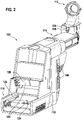
- FIG 2 10 is a perspective view of the back of the accessory device 100 according to FIG 1 shown.
- the docking area 118 which includes both mechanical and electrical interface elements 120 .
- the accessory device 100 is pushed onto the housing 12 of the handheld power tool 10 along guide rails 122 , which are arranged parallel to the working axis 28 .
- a spring-loaded form-fitting element 124 of the accessory device 100 snaps into a corresponding undercut element (not shown) on the housing 12 of the handheld power tool 10 .
- the accessory device 100 can be connected to the hand-held power tool 10 in a captive manner by the guide rails 122 and the positive-locking element 124 .
- the connection can be established by actuating a connecting element 126 (see figure 1 ) are released, with actuation of the connecting element 126 causing a displacement of the form-fitting element 124 against the spring force.
- the coupling region 118 includes an electrical interface 128 that includes three electrical contacts, which is designed to electrically connect the accessory device 100 to the handheld power tool 10 via a connection to an electrical interface (not shown) on the handheld power tool 10 .
- the fan unit 104 can be supplied with energy by the energy supply unit 20 of the hand-held power tool 10 via the electrical interface 128 .
- the fan unit 104 can be electrically connected via the electrical interface 128 to control electronics 15 of the handheld power tool 10, in particular the operating switch 18 of the handheld power tool 10, so that actuation of the operating switch 18 activates the fan unit 104 or the accessory device 100.
- the suction head 112 includes a dust pick-up element 130 which has an opening 132 which is arranged concentrically around the working axis 28 of the hand-held power tool 10 .
- the dust pick-up element 130 is releasably connected to an adapter element 134 which is also assigned to the suction head 112 and fastened to the telescopic unit 114 .
- the suction head 112 is designed as the first section of the air duct 105 .
- the second section of the air duct 105 is formed by an elastic hose element 136 in which a metallic spring spiral 138 is incorporated.
- the tube element 136 is mounted radially in a telescopic element 140 of the telescopic unit 114 , the telescopic element 140 being mounted in the housing 102 of the accessory device 100 so that it can move axially.
- the hose element 136 encloses the adapter element 134 at a first end.
- An inlet opening 144 of the dust collection box 110 is arranged downstream of the elbow element 142 in the direction of flow.
- the dust collection box 110 has a filter unit 146 which is designed to filter dust particles from the air flow.
- the filter unit 146 includes a frame member 148 to which a filter element 150 is attached.
- the filter element 150 is designed as a pleated filter, for example.
- the filter unit 146 is detachably connected to the dust collection box 110.
- the filter unit 146 is arranged at an outlet opening 147 of the dust collection box 110 through which the air flow leaves the dust collection box 110 .
- the dust collection box 110 has a first sealing element 152 and a second sealing element 154 .
- the first sealing element 152 is arranged on the dust collection box side on the filter unit 146 .
- the second sealing element 154 is arranged on the filter unit 146 on the accessory device side.
- the first sealing element 152 acts on the dust collection box 110 on at least one side and the second sealing element 154 acts on the housing 102 of the accessory device 100 on at least one side.
- the dust collection box 110 In order to additionally seal the dust collection box 110 on the side of the outlet opening 147, the dust collection box 110, in particular the second Sealing means 154 of the dust collection box 110, the housing 102 of the accessory device 100 via a housing element 156 mounted with play.
- An elastic tolerance compensation element 158 is additionally arranged between the housing element 156 and the housing 102 , which is embodied as a rubber ring, for example, and can be deformed when the dust collection box 110 is connected to the accessory device 100 .
- FIG. 4 A perspective view of the filter unit 146 of the dust collection box 110 is shown.
- the frame element 148 completely encloses the filter element 150 laterally.
- the frame member 148 is bent perpendicularly outward at its top edge 160 .
- the first sealing element 152 and the second sealing element 154 are arranged on opposite side surfaces, in particular circumferentially, on this upper edge 160 bent outwards.
- the filter unit 146 is detachably connected to the dust collection box 110 by means of a second fastening unit 162 .
- the second fastening unit 162 has two opposite actuating elements 164 which are advantageously formed centrally on the upper edge 160 of the frame element 148 .
- the actuating elements 164 of the second fastening unit 162 extend in the direction of a lower edge 166 of the frame element 148 and each have an undercut element 168 .
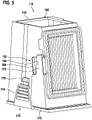
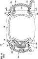
- FIG 5 A perspective view of the dust collection box 110 with the filter unit 146 installed is shown.
- the housing 115 of the dust collection box 110 has two opposite pockets 170 which are assigned to the second fastening unit 162 .
- the actuating elements 164 are inserted into the pockets 170, the actuating elements 164 initially deflecting inwards until the undercut elements 168 engage with the rear end of the pocket 170 and the actuating elements 164 relax.
- the filter unit 146 is thus non-positively and positively connected to the housing 115 of the dust collection box 110 .
- the undercut can be released again by pressing the actuating elements 164 inwards.
- the dust collection box 110 has a base 172 which is screwed to the housing 115 of the dust collection box. Molded onto the standing surface 172 are two opposing resilient actuating elements 174 which are associated with the first fastening unit 113 .
- the actuating elements 174 extend essentially parallel to the housing 115 and end in a locking lug 176.
- the locking lugs 176 of the first fastening unit 113 snap into corresponding pockets 178 (see 6 ) on the inside of the housing 102 of the accessory device 100.
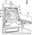
- the housing 102 of the accessory device 100 is according to FIG 1 composed of a first housing half-shell 180 and a second housing half-shell 182. During assembly, the two housing half-shells 180, 182 are connected to one another by means of screw connections along a connection plane that runs through the edge edges 184 of the housing half-shells 180, 182.
- the second housing half-shell 182 is shown with the electric motor 106 inserted.
- the electric motor 106 is attached to a receiving flange 186 via a screw connection.
- the receiving flange 186 is designed as a flat metal plate.
- the electric motor 106 is fastened to the receiving flange 186 at a first front end 188 of the electric motor 106.
- a receiving pocket 190 is formed in the second housing half-shell 182, into which the receiving flange 186 connected to the electric motor 106 can be inserted. Since the electric motor 106 only at one end, namely the first front end 188 of the electric motor 106 is held in the housing 102, the bearing of the electric motor 106 is heavily loaded in this area during operation of the electric motor 106 by vibrations that occur.
- the accessory device 100 has a damping unit 192 .
- the damping unit 192 comprises, for example, two damping elements 194 which are arranged, in particular molded, on the inside of the second housing half-shell 182 .
- the damping elements 194 are designed as cantilever elements.
- the damping elements 194 extend in a straight direction from the inside of the housing half-shell 182 and past the connecting plane of the housing half-shells 180,182.
- the damping elements 194 are in contact with the outer peripheral surface 196 of the electric motor 106 .
- the damping elements 194 are advantageously arranged in such a way that, when they are in contact with the electric motor 106, they apply a force radially to the latter on both sides.
- the distance between the two damping elements 194, in particular at their free end 198, is less than the diameter of the electric motor 106.
- the damping elements 194 are at their free end 198 rounded inward. In this way, the two damping elements 194 can bend away from each other during insertion.
- the damping elements 194 are arranged above and below the electric motor 106 so that the damping unit 192 acts along the force of gravity during operation.
- the electric motor 106 is supported laterally by the housing 102 of the accessory device 100 .
- the degree of damping by the damping unit 192 can be adjusted via various parameters, such as the number of damping elements 194, the positioning of the damping elements 194, the stiffness of the damping elements 194 and/or the nature of a contact surface 200 of the damping elements 194.
- the rigidity of the damping elements 194 results in particular from the distance from the origin of the damping elements 194 the inside of the housing 102 from the contact surface 200 and the thickness 202 of the damping elements 194.
- the nature of the contact surface 200 of the damping elements 194 can be realized, for example, by changing the roughness of the contact surface 200, for example by mechanical or chemical surface treatment or by coating the surface .
- the damping element is in contact with the electric motor 106 in the area of the contact surface 200 .
- the accessory device 100 When working with the hand-held power tool 10, dust particles of different sizes, ranging from a few ⁇ m to the mm range, can be detached from the processing surface.
- the accessory device 100 has air guiding elements 204 which prevent large dust particles from penetrating directly into the housing 102 .
- the air guiding elements 204 are formed inwards as housing ribs on the housing 102 of the accessory device.
- the air guiding elements 204 are arranged in the area of the air passage openings 109 in such a way that the incoming air or dust particles are deflected in their trajectory.
- all dust particles moving perpendicularly from the outside in the direction of the electric motor 106 are deflected downwards by approximately 90° by the air guiding elements 204 , for example.
- FIG 8 a perspective partial view of the inside of the second housing half-shell 182 is shown.
- the air guide elements 204 are curved inwards in the area of the air passage openings 109 (see FIG 8 ).
- a region on the inside of the housing half-shell 182, which includes the air guiding elements 204, is formed by a support element 206 supporting the electric motor 106, in particular laterally.
- Three air guide elements 204 are surrounded by the support element 206 by 360°; two air guiding elements 204 are enclosed by the support element 206 by approximately 210°. Because the support elements 206 enclose the air guiding elements 204 by at least 180°, the support elements 206 form filter receiving pockets 210 into which a shown filter element can be used.
- the filter element may be formed from a filter foam, such as ether or ester foam.
- the filter foam is advantageously made from a reticulated polyurethane foam.
- the filter foam also advantageously has a pore size of 10 ppi to 90 ppi.
- the air guide elements 204 and the support elements 206 are advantageously formed in one piece with the housing 102, which enables the accessory device 100 to be produced in a particularly cost-effective manner.
- the electric motor 106 has at least one air inlet 214 and at least one air outlet 216 (see FIG 6 ).
- the air inlet 214 is arranged opposite the front end 188 of the electric motor 106, while the air outlets 216 are arranged laterally.
- the air passage openings 109 are arranged in the area of the air outlets 216 in order to prevent the electric motor 106 from directly sucking in its warm exhaust air again.
- a straight line extending perpendicularly from an axis of rotation of electric motor 106 first intersects air outlet 216, then the filter element, air guiding element 204 and finally air passage opening 109.
- support element 206 encloses air passage openings 109 and air outlet 216 in such a way that a closed Exhaust duct is formed.
- FIG. 12 is a perspective view of the suction head 112 of the accessory device 100, with the dust pickup member 130 shown detached from the adapter member 134.
- the dust pick-up element 130 bears against the working surface.
- the dust pick-up element 130 is applied to the surface to be processed via contact surfaces 218, the contact surfaces 218 being arranged around a working area 220 in which the insert tool 14 is processing the processing surface.
- the suction head 112 comprises four contact surfaces 218 which extend in the direction of the processing surface.
- the contact surfaces 218 are advantageously arranged on a circular path 222 around the work area 220, with the center points of the contact surfaces 218 being spaced apart from one another by approximately 90°.
- the contact surfaces 218 act on the surface to be machined, in particular along at most 50% of the circular path 222, advantageously at most 30% of the circular path 222 and particularly preferably at most 15% of the circular path 222.
- the contact of the contact surfaces 218 with the processing surface forms at least one gap between the processing surface and the dust collection element 130.
- a lot of air can be sucked in by the accessory device 100 through this gap , which significantly increases the effectiveness of removing dust at the point of use of the application tool 14 .
- the contact surfaces 218 are advantageously made of a non-yielding material, in particular a non-yielding plastic.
- the dust pick-up element 130 is designed so that it can be connected to the adapter element 134 by being pushed into it (cf. 3 ). It is pushed in from above or perpendicular to the axial movement of the telescopic unit 114.
- the connection is made in particular in a non-positive and positive manner by corresponding connecting elements 224, 226, for example by a snap connection.
- the connecting element 224 of the dust receiving element 130 is advantageously designed as a form-fitting element that engages in the connecting element 226 of the adapter element 134, which is designed as a corresponding recess in a wall of the adapter element 134.
- the connecting element 224 of the dust receiving element 130 protrudes beyond the wall of the adapter element 134 (seen in 2 ).
- the adapter element 134 is attached to the accessory device 100 by means of screws which are guided in screw bosses 227 .
- the air duct 105 of the accessory device 100 can advantageously be easily examined and cleaned in a straight line via the partially open end 228 of the adapter element 134 on the processing surface side.
- an alternative embodiment of the suction head 112 is shown in a longitudinal section.
- the adapter element 134 has the same structure as in the previous exemplary embodiment and is detachably connected to a further dust-receiving element 230 .
- the further dust pick-up element 230 differs from the dust pick-up element 130 in its length.
- the further dust pick-up element 230 ends essentially flush with the adapter element 134 . Only the contact surfaces 218 of the further dust collection element 230 stand out towards the front. The length of the accessory device 100 is thus not significantly changed by the further dust pick-up element 230 .
- the length of the accessory device 100 is significantly increased.
- the axial distance between the front end 232 of the suction head 112 and the tool holder 16 of the hand-held power tool 10 can be changed. This can be used, for example, to always be able to utilize the entire range of axial movement of the telescopic unit 114 . If, for example, the handheld power tool 10 with the tool holder 16 designed as an interchangeable drill chuck is replaced by a handheld power tool with a fixed drill chuck, the resulting reduced length of the handheld power tool can be compensated for by the additional dust pick-up element 230 .
- the air is guided essentially in a straight line within the further dust absorption element 230 .
- the air can be guided on an essentially circular arc-like or elliptical path in the dust pickup element 130, which is longer, so that the suction head can be optimized in terms of flow.
- FIG. 11 is a partial view of a section through the in 1 drawn level B shown.
- the section shows a housing guide 234 for the telescopic unit 114, in which in particular the telescopic element 140 of the telescopic unit 114 is mounted in the housing 102 so that it can move axially. Furthermore, part of an actuating mechanism 236 of the telescopic unit 114 is also shown, which is designed to prevent a movement of the telescopic unit 114 in the non-actuated state.
- the housing guide 234 includes guide elements 238 which are designed as guide rails, for example.
- the guide elements 238 are arranged in the housing 102 of the accessory device 100 in such a way that, in the assembled state, the telescopic unit 114, in particular the telescopic element 140, is guided on at least one side surface of the guide elements 238.
- the guide elements 238 are formed on the inside of the housing 102 .
- the guide elements 238 can be formed by separate housing elements.
- the contact surfaces of the telescopic unit 114 with the guide elements 238 represent wear surfaces 240, since at this point friction occurs between the telescopic unit 114 and the housing guide 234 with every movement of the telescopic unit 114 . In order to ensure that the telescopic unit 114 can be displaced in the housing guide 234, a small amount of play is provided between the contact surfaces.
- An alternative embodiment of the accessory device 100 is shown, which essentially has all the features of the accessory device 100 described above and, for example, has securing elements 242 which counteract wear on the wear surfaces 240 .
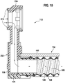
- the longitudinal section 12 runs along the in 11 drawn-in level C.
- the accessory device 100 has, for example, three different securing elements 242 which are arranged between the telescopic unit 114 and the housing 102 .
- the securing elements 242 are attached to the housing 102 of the accessory device 100, for example, but it is also conceivable that the securing elements 242 are attached to the telescopic unit 114.
- the securing elements 242 are in the form of mechanical energy storage elements 244 .
- the telescopic unit 114 in particular the telescopic element 140, is pretensioned by the securing elements 242 in a first direction 246 and in a direction 248 opposite the first direction.
- the first direction 246 corresponds to the direction of gravity.
- the first securing element 242 is designed as a spring plate 249 .
- the spring plate 249 rests centrally on the telescopic element 140 and prestresses it in the direction of its spring force.
- the second securing element 242 is designed as a ball pressure piece 250 .
- the ball pressure piece 250 is formed from a spring-loaded ball, which is mounted in the housing 102 of the accessory device 100 .
- the third securing element 242 is designed as a locking cap 252 .
- the telescope unit 114 is in 12 shown in an extended condition.
- the housing 102 encloses the telescopic unit 114 in an input area 254.
- the wearing surfaces 240 within this input area 254 are stressed with every movement of the telescopic unit 114, in contrast to the wearing surfaces 240 outside of this input area 254.
- the securing elements 242 are therefore advantageously arranged in the entry area 254 .
- a securing element 242 that does not generate any preload but is installed in such a way that a contact surface 241 of the securing element 242 becomes a wear surface only after a wear threshold has been reached.
- the fuse element 242 is in 13 for example as a metallic element, in particular a screw 255, which is accommodated by the housing 102 of the accessory device 100.
- the screw 255 is arranged in the housing 102 such that there is no contact between the screw 255 and the telescopic member 140 in a non-wear state of the accessory device. It is also conceivable that the screw 255 is initially countersunk in the screw hole 257 .
- the distance 259 between a screw head of the screw 255 and the top of a screw hole 257 defines a wear threshold. After the upper end of the screw hole 257 has been worn through friction, the wear threshold would be reached and the securing element 242 in the form of the screw 255 comes into contact with the telescopic element 140.
- the telescopic element 140 is formed from a metallic material, in particular aluminum, and the guide elements 243 are made from plastic.
- the telescopic element 140 and the guide elements 238 advantageously form a plastic/metal pairing, which further reduces wear.
- Sensor unit 258 includes a motor sensor element 260, which is designed to detect the speed of electric motor 106, and an in particular electronic air sensor element 262, which is designed to detect a change in the pressure and/or the volume flow within accessory device 100.
- a combination of the motor sensor element 260 with the electronic air sensor element 262 is not absolutely necessary for the functionality of the sensor unit 258, but can be used to increase the accuracy of the detection.
- Sensor unit 258 also has a control unit 264 which is designed to evaluate the signal from motor sensor element 260 and from air sensor element 262 .
- the engine sensor element 260 is designed as part of the electronics 205 of the accessory device 100, for example.
- the electronics 205 of the accessory device 100 are designed in particular to control the electric motor 106 .
- a change in the pressure and/or the volume flow results in a change in the speed of the electric motor 106 , which can be measured by the electronics 205 via the current applied to the electric motor 106 .
- the air sensor element 262 is designed, for example, as a commercially available pressure sensor 263 which is electrically connected to the control unit 264 .
- the air sensor element 262 is advantageously arranged in the area of the fan element 108 .
- the control unit 264 detects the input signals of the motor sensor element 260 and the air sensor element 262 and determines the state of the accessory device 100 on the basis of a comparison of the values of the input signals or the change in the input signals over time Accessory device 100, an error signal is issued.
- the error signal is output in particular via a communication interface 266 which is designed for the wireless transmission 267 of information to a display unit 268 .
- Display unit 268 is embodied, for example, as a smartphone 270, which receives the error signal from sensor unit 258 and, depending on the error signal, controls an optical display element 272, a haptic display element 274 and/or an acoustic display element 276.
- the error signal can be output optically via the optical display element 272 designed as a screen, haptically via the haptic display element 274 designed as a vibration mechanism and acoustically through the acoustic display element 276 designed as a loudspeaker.
- the display unit 268 is at least partially arranged on the housing 102 of the accessory device 100 or on the housing 12 of the hand-held power tool 10 .
- the communication interface 266 can be designed to transmit the error signal to the display unit 268 via an electrical contact and/or via a wireless connection.
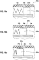
- a fourth embodiment of the accessory device 100a is shown with an alternative embodiment of the sensor unit 258a in which the display element 272a of the display unit 268a is designed as a level indicator.
- This embodiment also differs from the previous embodiments in that the accessory device 100a does not have a fan unit.
- the air flow required for accessory device 100a is generated instead of by the fan unit via motor cooling 30a of hand-held power tool 10a, and air duct 105a of accessory device 100a runs from suction head 112a of accessory device 100a via a filter element 212a to air outlet openings 32a on the top of the housing 12a of the hand-held power tool 10a are arranged.
- Motor cooling 30a of hand-held power tool 10a preferably includes a fan element which is designed as a double fan.
- the fan element of hand-held power tool 10a advantageously comprises two different air-guiding or blade geometries, one air-guiding geometry being provided for supplying the electric motor of hand-held power tool 10a with cooling air and the other air-guiding geometry being provided for supplying accessory device 100a with cooling air.
- the air outlet openings 32a are advantageously shaped in such a way that the outflowing air is guided out of the hand-held power tool 10a asymmetrically, advantageously away from the user.
- the housing 102a of the accessory device 100a and the housing 12a of the handheld power tool 10a have mutually corresponding transition openings 34a, 280a, through which the air flow can penetrate from the accessory device 100a into the handheld power tool 10a.
- the transition openings 34a, 280a are arranged below the motor cooling system 30a of the hand-held power tool 10a and above the filter element 212a. It is conceivable to arrange the sensor unit 258a at different positions, in particular behind the filter element 212a in the direction of flow.
- the sensor unit 258a is advantageously arranged on the upper side of the housing 12a of the hand-held power tool 10a, in particular in the region of the air outlet openings 32a.
- the sensor unit 258a on a mechanical air sensor element 262a which is movably mounted against a spring force.
- a change in the pressure or the volume flow in the area of the mechanical air sensor element 262a leads to a change in the position of the mechanical air sensor element 262a.
- Movement of a visual indicator element 272a is coupled to movement of the mechanical air sensing element 262a.
- the housing 12a of the hand-held power tool 10a has a window or an opening 36a through which the position of the display element 272a can be tracked, the fill level of the dust collection box 110a of the accessory device 100a being able to be determined by the position of the display element 272a.
- the position of the indicator 272a indicates an empty dust collection box 110a; in Figure 16b the position of the indicator 272a indicates a full dust collection box 110a; in Figure 16c the handheld power tool 10a is switched off.
Landscapes
- Engineering & Computer Science (AREA)
- Mechanical Engineering (AREA)
- Percussive Tools And Related Accessories (AREA)
- Auxiliary Devices For Machine Tools (AREA)
- Portable Power Tools In General (AREA)
Applications Claiming Priority (2)
| Application Number | Priority Date | Filing Date | Title |
|---|---|---|---|
| DE102017201558.6A DE102017201558A1 (de) | 2017-01-31 | 2017-01-31 | Zubehörvorrichtung für eine Handwerkzeugmaschine |
| PCT/EP2017/079700 WO2018141430A1 (de) | 2017-01-31 | 2017-11-20 | Zubehörvorrichtung für eine handwerkzeugmaschine |
Publications (2)
| Publication Number | Publication Date |
|---|---|
| EP3576905A1 EP3576905A1 (de) | 2019-12-11 |
| EP3576905B1 true EP3576905B1 (de) | 2023-01-11 |
Family
ID=60954986
Family Applications (1)
| Application Number | Title | Priority Date | Filing Date |
|---|---|---|---|
| EP17828655.5A Active EP3576905B1 (de) | 2017-01-31 | 2017-11-20 | Zubehörvorrichtung für eine handwerkzeugmaschine |
Country Status (5)
| Country | Link |
|---|---|
| US (1) | US11123830B2 (zh) |
| EP (1) | EP3576905B1 (zh) |
| CN (1) | CN110234466B (zh) |
| DE (1) | DE102017201558A1 (zh) |
| WO (1) | WO2018141430A1 (zh) |
Families Citing this family (11)
| Publication number | Priority date | Publication date | Assignee | Title |
|---|---|---|---|---|
| US10814468B2 (en) | 2017-10-20 | 2020-10-27 | Milwaukee Electric Tool Corporation | Percussion tool |
| CN214723936U (zh) | 2018-01-26 | 2021-11-16 | 米沃奇电动工具公司 | 冲击工具 |
| CN215968574U (zh) | 2018-11-19 | 2022-03-08 | 米沃奇电动工具公司 | 适于与手持式电动工具一起使用的集尘器 |
| DE102018222772A1 (de) * | 2018-12-21 | 2020-06-25 | Robert Bosch Gmbh | Abnehmbare Staubauffangvorrichtung, insbesondere abnehmbarer Staubauffangbehälter, für eine Handwerkzeugmaschine |
| CN111745595B (zh) | 2019-03-26 | 2023-09-12 | 株式会社牧田 | 集尘系统 |
| JP7181136B2 (ja) * | 2019-03-26 | 2022-11-30 | 株式会社マキタ | 集塵システム |
| DE102020207395A1 (de) | 2020-06-16 | 2021-12-16 | Robert Bosch Gesellschaft mit beschränkter Haftung | Staubsaugvorrichtung |
| DE102020209075A1 (de) | 2020-07-20 | 2022-01-20 | Robert Bosch Gesellschaft mit beschränkter Haftung | Absaugvorrichtung |
| JP1715011S (ja) * | 2020-12-11 | 2022-05-16 | コードレスハンマードリル | |
| CN113182557B (zh) * | 2021-04-18 | 2022-05-31 | 贾佑章 | 一种鸟笼生产用鸟笼底框钻孔设备 |
| GB2612637A (en) * | 2021-11-08 | 2023-05-10 | Black & Decker Inc | A power tool, power tool accessory and coupling arrangement therefor |
Family Cites Families (14)
| Publication number | Priority date | Publication date | Assignee | Title |
|---|---|---|---|---|
| DE4335417B4 (de) * | 1993-10-18 | 2006-11-30 | Hilti Ag | Absaugeinrichtung eines Bohr- oder Meisselgerätes |
| GB0613181D0 (en) * | 2006-07-01 | 2006-08-09 | Black & Decker Inc | Pavement breaker |
| DE102006029624A1 (de) * | 2006-06-28 | 2008-01-03 | Robert Bosch Gmbh | Staubauffangvorrichtung für eine Elktrohandwerkzeugmaschine |
| DE102006029625A1 (de) | 2006-06-28 | 2008-01-03 | Robert Bosch Gmbh | Absaugvorrichtung einer Elektrohandwerkzeugmaschine sowie Elektrohandwerkzeugmaschine mit Absaugvorrichtung |
| US7909114B2 (en) * | 2007-02-23 | 2011-03-22 | Hitachi Koki Co., Ltd. | Drilling device |
| DE102007036783A1 (de) | 2007-08-03 | 2009-02-05 | Robert Bosch Gmbh | Handwerkzeugmaschine mit einer Staubabsaugungseinrichtung |
| US9776296B2 (en) * | 2008-05-09 | 2017-10-03 | Milwaukee Electric Tool Corporation | Power tool dust collector |
| JP5336273B2 (ja) * | 2009-06-23 | 2013-11-06 | 株式会社マキタ | ダストボックス及び電動工具 |
| JP2011189484A (ja) | 2010-03-16 | 2011-09-29 | Makita Corp | 集塵装置及び集塵装置付き電動工具 |
| JP5448951B2 (ja) * | 2010-03-16 | 2014-03-19 | 株式会社マキタ | アタッチメント付き電動工具の駆動源供給システム |
| JP5525963B2 (ja) * | 2010-08-20 | 2014-06-18 | 株式会社マキタ | 集塵装置付き電動工具 |
| JP5739306B2 (ja) * | 2011-04-26 | 2015-06-24 | 株式会社マキタ | 電動工具用集塵装置及び電動工具 |
| DE102011087361B3 (de) | 2011-11-29 | 2013-01-31 | Hilti Aktiengesellschaft | Absaugvorrichtung und Steuerungsverfahren |
| US10507556B2 (en) | 2016-01-20 | 2019-12-17 | Makita Corporation | Dust collector for electric power tool, electric power tool, and dust collection system |
-
2017
- 2017-01-31 DE DE102017201558.6A patent/DE102017201558A1/de not_active Withdrawn
- 2017-11-20 EP EP17828655.5A patent/EP3576905B1/de active Active
- 2017-11-20 US US16/479,560 patent/US11123830B2/en active Active
- 2017-11-20 WO PCT/EP2017/079700 patent/WO2018141430A1/de unknown
- 2017-11-20 CN CN201780085226.8A patent/CN110234466B/zh active Active
Also Published As
| Publication number | Publication date |
|---|---|
| WO2018141430A1 (de) | 2018-08-09 |
| US20190358758A1 (en) | 2019-11-28 |
| CN110234466A (zh) | 2019-09-13 |
| EP3576905A1 (de) | 2019-12-11 |
| US11123830B2 (en) | 2021-09-21 |
| DE102017201558A1 (de) | 2018-08-02 |
| CN110234466B (zh) | 2022-06-28 |
Similar Documents
| Publication | Publication Date | Title |
|---|---|---|
| EP3576905B1 (de) | Zubehörvorrichtung für eine handwerkzeugmaschine | |
| DE102017201565A1 (de) | Zubehörvorrichtung für eine Handwerkzeugmaschine | |
| EP2474387B1 (de) | Absaugvorrichtung einer Elektrohandwerkzeugmaschine sowie Elektrohandwerkzeugmaschine mit Absaugvorrichtung | |
| EP2081739A1 (de) | System mit einer handwerkzeugmaschine | |
| DE102015226021A1 (de) | Absaugvorrichtung | |
| DE112015000823T5 (de) | Staubsammler und Arbeitswerkzeug, das mit einem Staubsammler vorgesehen ist | |
| EP3484661B1 (de) | Absaughaube für werkzeugmaschine | |
| WO2008080649A1 (de) | Handwerkzeugmaschine mit einer saugeinheit | |
| EP2476520B1 (de) | Elektrowerkzeugmaschine, insbesondere eine Schleif- oder Poliermaschine | |
| DE202012007437U1 (de) | Absaugvorrichtung | |
| DE102017201567A1 (de) | Zubehörvorrichtung für eine Handwerkzeugmaschine | |
| EP2363237B1 (de) | Staubsaugvorrichtung für eine Bohrmaschine | |
| DE102005062464A1 (de) | Absaugvorrichtung für eine Handwerkzeugmaschine | |
| EP2043815B1 (de) | Staubabsaugadaptervorrichtung | |
| DE102017201563A1 (de) | Zubehörvorrichtung für eine Handwerkzeugmaschine | |
| DE102017201560A1 (de) | Zubehörvorrichtung für eine Handwerkzeugmaschine | |
| EP2228171A1 (de) | Handwerkzeugmaschinenvorrichtung | |
| EP3431227B1 (de) | An eine absaugvorrichtung anschliessbare handwerkzeugmaschine | |
| DE2940362A1 (de) | Mit einem elektrisch angetriebenen bohrhammer kombinierbare staubabsaugeinheit | |
| EP1923149B1 (de) | Absaugeinrichtung für ein motorisch angetriebenes Handwerkzeuggerät | |
| EP3843941B1 (de) | Staubabsaugvorrichtung | |
| DE102018124324B3 (de) | Werkzeugmaschinensystem mit Ersatzlast | |
| DE102016108941A1 (de) | Handwerkzeug und Verfahren zum Betreiben eines Handwerkzeuges | |
| DE102020209074A1 (de) | Befestigungsvorrichtung für eine Absaugvorrichtung | |
| EP3603864A1 (de) | Mobiles absaugmodul für stichsäge |
Legal Events
| Date | Code | Title | Description |
|---|---|---|---|
| STAA | Information on the status of an ep patent application or granted ep patent |
Free format text: STATUS: UNKNOWN |
|
| STAA | Information on the status of an ep patent application or granted ep patent |
Free format text: STATUS: THE INTERNATIONAL PUBLICATION HAS BEEN MADE |
|
| PUAI | Public reference made under article 153(3) epc to a published international application that has entered the european phase |
Free format text: ORIGINAL CODE: 0009012 |
|
| STAA | Information on the status of an ep patent application or granted ep patent |
Free format text: STATUS: REQUEST FOR EXAMINATION WAS MADE |
|
| 17P | Request for examination filed |
Effective date: 20190902 |
|
| AK | Designated contracting states |
Kind code of ref document: A1 Designated state(s): AL AT BE BG CH CY CZ DE DK EE ES FI FR GB GR HR HU IE IS IT LI LT LU LV MC MK MT NL NO PL PT RO RS SE SI SK SM TR |
|
| AX | Request for extension of the european patent |
Extension state: BA ME |
|
| RAP1 | Party data changed (applicant data changed or rights of an application transferred) |
Owner name: ROBERT BOSCH GMBH |
|
| DAV | Request for validation of the european patent (deleted) | ||
| DAX | Request for extension of the european patent (deleted) | ||
| GRAP | Despatch of communication of intention to grant a patent |
Free format text: ORIGINAL CODE: EPIDOSNIGR1 |
|
| STAA | Information on the status of an ep patent application or granted ep patent |
Free format text: STATUS: GRANT OF PATENT IS INTENDED |
|
| INTG | Intention to grant announced |
Effective date: 20220916 |
|
| GRAS | Grant fee paid |
Free format text: ORIGINAL CODE: EPIDOSNIGR3 |
|
| GRAA | (expected) grant |
Free format text: ORIGINAL CODE: 0009210 |
|
| STAA | Information on the status of an ep patent application or granted ep patent |
Free format text: STATUS: THE PATENT HAS BEEN GRANTED |
|
| AK | Designated contracting states |
Kind code of ref document: B1 Designated state(s): AL AT BE BG CH CY CZ DE DK EE ES FI FR GB GR HR HU IE IS IT LI LT LU LV MC MK MT NL NO PL PT RO RS SE SI SK SM TR |
|
| REG | Reference to a national code |
Ref country code: GB Ref legal event code: FG4D Free format text: NOT ENGLISH |
|
| REG | Reference to a national code |
Ref country code: CH Ref legal event code: EP |
|
| REG | Reference to a national code |
Ref country code: DE Ref legal event code: R096 Ref document number: 502017014332 Country of ref document: DE |
|
| REG | Reference to a national code |
Ref country code: IE Ref legal event code: FG4D Free format text: LANGUAGE OF EP DOCUMENT: GERMAN |
|
| REG | Reference to a national code |
Ref country code: AT Ref legal event code: REF Ref document number: 1543119 Country of ref document: AT Kind code of ref document: T Effective date: 20230215 |
|
| REG | Reference to a national code |
Ref country code: LT Ref legal event code: MG9D |
|
| REG | Reference to a national code |
Ref country code: NL Ref legal event code: MP Effective date: 20230111 |
|
| PG25 | Lapsed in a contracting state [announced via postgrant information from national office to epo] |
Ref country code: NL Free format text: LAPSE BECAUSE OF FAILURE TO SUBMIT A TRANSLATION OF THE DESCRIPTION OR TO PAY THE FEE WITHIN THE PRESCRIBED TIME-LIMIT Effective date: 20230111 |
|
| PG25 | Lapsed in a contracting state [announced via postgrant information from national office to epo] |
Ref country code: RS Free format text: LAPSE BECAUSE OF FAILURE TO SUBMIT A TRANSLATION OF THE DESCRIPTION OR TO PAY THE FEE WITHIN THE PRESCRIBED TIME-LIMIT Effective date: 20230111 Ref country code: PT Free format text: LAPSE BECAUSE OF FAILURE TO SUBMIT A TRANSLATION OF THE DESCRIPTION OR TO PAY THE FEE WITHIN THE PRESCRIBED TIME-LIMIT Effective date: 20230511 Ref country code: NO Free format text: LAPSE BECAUSE OF FAILURE TO SUBMIT A TRANSLATION OF THE DESCRIPTION OR TO PAY THE FEE WITHIN THE PRESCRIBED TIME-LIMIT Effective date: 20230411 Ref country code: LV Free format text: LAPSE BECAUSE OF FAILURE TO SUBMIT A TRANSLATION OF THE DESCRIPTION OR TO PAY THE FEE WITHIN THE PRESCRIBED TIME-LIMIT Effective date: 20230111 Ref country code: LT Free format text: LAPSE BECAUSE OF FAILURE TO SUBMIT A TRANSLATION OF THE DESCRIPTION OR TO PAY THE FEE WITHIN THE PRESCRIBED TIME-LIMIT Effective date: 20230111 Ref country code: HR Free format text: LAPSE BECAUSE OF FAILURE TO SUBMIT A TRANSLATION OF THE DESCRIPTION OR TO PAY THE FEE WITHIN THE PRESCRIBED TIME-LIMIT Effective date: 20230111 Ref country code: ES Free format text: LAPSE BECAUSE OF FAILURE TO SUBMIT A TRANSLATION OF THE DESCRIPTION OR TO PAY THE FEE WITHIN THE PRESCRIBED TIME-LIMIT Effective date: 20230111 |
|
| PG25 | Lapsed in a contracting state [announced via postgrant information from national office to epo] |
Ref country code: SE Free format text: LAPSE BECAUSE OF FAILURE TO SUBMIT A TRANSLATION OF THE DESCRIPTION OR TO PAY THE FEE WITHIN THE PRESCRIBED TIME-LIMIT Effective date: 20230111 Ref country code: PL Free format text: LAPSE BECAUSE OF FAILURE TO SUBMIT A TRANSLATION OF THE DESCRIPTION OR TO PAY THE FEE WITHIN THE PRESCRIBED TIME-LIMIT Effective date: 20230111 Ref country code: IS Free format text: LAPSE BECAUSE OF FAILURE TO SUBMIT A TRANSLATION OF THE DESCRIPTION OR TO PAY THE FEE WITHIN THE PRESCRIBED TIME-LIMIT Effective date: 20230511 Ref country code: GR Free format text: LAPSE BECAUSE OF FAILURE TO SUBMIT A TRANSLATION OF THE DESCRIPTION OR TO PAY THE FEE WITHIN THE PRESCRIBED TIME-LIMIT Effective date: 20230412 Ref country code: FI Free format text: LAPSE BECAUSE OF FAILURE TO SUBMIT A TRANSLATION OF THE DESCRIPTION OR TO PAY THE FEE WITHIN THE PRESCRIBED TIME-LIMIT Effective date: 20230111 |
|
| REG | Reference to a national code |
Ref country code: DE Ref legal event code: R097 Ref document number: 502017014332 Country of ref document: DE |
|
| PG25 | Lapsed in a contracting state [announced via postgrant information from national office to epo] |
Ref country code: SM Free format text: LAPSE BECAUSE OF FAILURE TO SUBMIT A TRANSLATION OF THE DESCRIPTION OR TO PAY THE FEE WITHIN THE PRESCRIBED TIME-LIMIT Effective date: 20230111 Ref country code: RO Free format text: LAPSE BECAUSE OF FAILURE TO SUBMIT A TRANSLATION OF THE DESCRIPTION OR TO PAY THE FEE WITHIN THE PRESCRIBED TIME-LIMIT Effective date: 20230111 Ref country code: EE Free format text: LAPSE BECAUSE OF FAILURE TO SUBMIT A TRANSLATION OF THE DESCRIPTION OR TO PAY THE FEE WITHIN THE PRESCRIBED TIME-LIMIT Effective date: 20230111 Ref country code: DK Free format text: LAPSE BECAUSE OF FAILURE TO SUBMIT A TRANSLATION OF THE DESCRIPTION OR TO PAY THE FEE WITHIN THE PRESCRIBED TIME-LIMIT Effective date: 20230111 Ref country code: CZ Free format text: LAPSE BECAUSE OF FAILURE TO SUBMIT A TRANSLATION OF THE DESCRIPTION OR TO PAY THE FEE WITHIN THE PRESCRIBED TIME-LIMIT Effective date: 20230111 |
|
| PLBE | No opposition filed within time limit |
Free format text: ORIGINAL CODE: 0009261 |
|
| STAA | Information on the status of an ep patent application or granted ep patent |
Free format text: STATUS: NO OPPOSITION FILED WITHIN TIME LIMIT |
|
| PG25 | Lapsed in a contracting state [announced via postgrant information from national office to epo] |
Ref country code: SK Free format text: LAPSE BECAUSE OF FAILURE TO SUBMIT A TRANSLATION OF THE DESCRIPTION OR TO PAY THE FEE WITHIN THE PRESCRIBED TIME-LIMIT Effective date: 20230111 |
|
| 26N | No opposition filed |
Effective date: 20231012 |
|
| PGFP | Annual fee paid to national office [announced via postgrant information from national office to epo] |
Ref country code: GB Payment date: 20231123 Year of fee payment: 7 |
|
| PG25 | Lapsed in a contracting state [announced via postgrant information from national office to epo] |
Ref country code: SI Free format text: LAPSE BECAUSE OF FAILURE TO SUBMIT A TRANSLATION OF THE DESCRIPTION OR TO PAY THE FEE WITHIN THE PRESCRIBED TIME-LIMIT Effective date: 20230111 |
|
| PGFP | Annual fee paid to national office [announced via postgrant information from national office to epo] |
Ref country code: FR Payment date: 20231122 Year of fee payment: 7 |
|
| PGFP | Annual fee paid to national office [announced via postgrant information from national office to epo] |
Ref country code: DE Payment date: 20240123 Year of fee payment: 7 |