EP3576830B1 - Vorrichtung zum einstellen eines drainageventils - Google Patents
Vorrichtung zum einstellen eines drainageventils Download PDFInfo
- Publication number
- EP3576830B1 EP3576830B1 EP18705334.3A EP18705334A EP3576830B1 EP 3576830 B1 EP3576830 B1 EP 3576830B1 EP 18705334 A EP18705334 A EP 18705334A EP 3576830 B1 EP3576830 B1 EP 3576830B1
- Authority
- EP
- European Patent Office
- Prior art keywords
- axis
- actuator
- rotor
- locator
- valve
- Prior art date
- Legal status (The legal status is an assumption and is not a legal conclusion. Google has not performed a legal analysis and makes no representation as to the accuracy of the status listed.)
- Active
Links
Images

Classifications
-
- A—HUMAN NECESSITIES
- A61—MEDICAL OR VETERINARY SCIENCE; HYGIENE
- A61M—DEVICES FOR INTRODUCING MEDIA INTO, OR ONTO, THE BODY; DEVICES FOR TRANSDUCING BODY MEDIA OR FOR TAKING MEDIA FROM THE BODY; DEVICES FOR PRODUCING OR ENDING SLEEP OR STUPOR
- A61M27/00—Drainage appliance for wounds or the like, i.e. wound drains, implanted drains
- A61M27/002—Implant devices for drainage of body fluids from one part of the body to another
- A61M27/006—Cerebrospinal drainage; Accessories therefor, e.g. valves
-
- A—HUMAN NECESSITIES
- A61—MEDICAL OR VETERINARY SCIENCE; HYGIENE
- A61M—DEVICES FOR INTRODUCING MEDIA INTO, OR ONTO, THE BODY; DEVICES FOR TRANSDUCING BODY MEDIA OR FOR TAKING MEDIA FROM THE BODY; DEVICES FOR PRODUCING OR ENDING SLEEP OR STUPOR
- A61M2205/00—General characteristics of the apparatus
- A61M2205/35—Communication
- A61M2205/3507—Communication with implanted devices, e.g. external control
- A61M2205/3515—Communication with implanted devices, e.g. external control using magnetic means
-
- A—HUMAN NECESSITIES
- A61—MEDICAL OR VETERINARY SCIENCE; HYGIENE
- A61M—DEVICES FOR INTRODUCING MEDIA INTO, OR ONTO, THE BODY; DEVICES FOR TRANSDUCING BODY MEDIA OR FOR TAKING MEDIA FROM THE BODY; DEVICES FOR PRODUCING OR ENDING SLEEP OR STUPOR
- A61M39/00—Tubes, tube connectors, tube couplings, valves, access sites or the like, specially adapted for medical use
- A61M39/22—Valves or arrangement of valves
Definitions
- the present invention relates to a treatment device, in particular for adjusting a drainage valve intended for therapeutic applications, in particular the treatment of hydrocephalus.
- Treatment for hydrocephalus involves diverting cerebrospinal fluid (CSF) from the cerebral ventricles or the lumbar subarachnoid space to a site of resorption, for example the peritoneal cavity.
- CSF cerebrospinal fluid
- the rotation of the rotor causes the sliding of the contact point of the ball on the leaf spring, and therefore a modification of the opening pressure.
- the valve EP 688 575 comprises two micro-magnets mounted in the rotor and arranged on either side of the central axis of the chamber. These two micro-magnets can be magnetically coupled to a magnetic key, called an "external valve adjuster" in EP 688 575 , handled by an operator.
- the magnetic key has a magnetic bar made of a combination of magnets. The magnetic key thus makes it possible, from the outside, through skin tissue, to modify the angular position of the rotor, and therefore the minimum pressure allowing the liquid to move the valve to release the inlet duct, called “opening pressure”.
- the micro-magnets of the rotor are linearly movable in said rotor in a substantially radial direction thereof.
- the two micro-magnets are held, for example by mutual attraction, in a locked position of the rotor.
- the two micro-magnets can maintain respective lugs in cavities formed circularly in the chamber. Under the magnetic effect of the key, the two micro-magnets move to an unlocking position of the rotor, for example by extracting said pins from said cavities.
- the same key can advantageously be used to unlock the rotor, then to drive it in rotation.
- EP 2 236 169 describes a device for reading and adjusting an implantable valve.
- EP 2,865,408 describes a height-adjustable tool for locating an implantable valve, and reading and adjusting valve parameters magnetically.
- An objective of the present invention is to meet, at least partially, this need.
- the invention is defined by a device as in claim 1. Additional aspects are defined in dependent claims 2 to 12.
- the inventor has discovered that, depending on the insertion depth, the effect of magnetic coupling between the micro-magnet of the rotor and the magnet of the actuator is more favorable to the unlocking or the driving of the. rotor.
- the first insertion depth is particularly favorable for unlocking while the second insertion depth is more favorable for driving the rotor. In practice, it is therefore sufficient for the operator to press on the actuator to unlock, then to withdraw it partially before turning it to adjust the opening pressure.
- step a) to reach said predefined angular position, said valve is placed in a window of the locator, said window being shaped so that, when said valve is housed there, axes of orientation O V and O L of the valve and of said window are substantially parallel to one another and that the axis of rotation R of the rotor of the valve and the axis X are substantially the same.
- the method is used to adjust a valve implanted under the skin of a patient.
- the operator can rotate said actuator around the X axis in a guided manner.
- the movement of the actuator during this rotation is not necessarily a simple rotation around the X axis, but can be combined, for example, with a translation along the X axis and / or another rotation.
- the movement of the actuator during this rotation is a simple rotation around the X axis.
- guidance is meant that the operator who is content to turn the actuator around the X axis gives the actuator a predetermined movement. However, the operator can quit guidance. For example, in the embodiment described in detail below, he can press the actuator to push it into the locator housing.
- a device according to the invention can be used in particular for the implementation of a said adjustment method.
- the valve may in particular include one or more of the characteristics of the valves described in EP 688 575 or in EP 3 046 614 .
- it comprises exactly two micro-magnets mounted in the rotor and arranged on either side of the axis of the rotor.
- Rotation of the rotor modifies the compression of the shutter by the elastic return member, and therefore modifies the opening pressure of the valve.
- the rotor is only movable in rotation about the axis of rotation. In particular, it is not mobile in translation along this axis.
- the actuator magnet exerts a magnetic field suitable for, when the locator is placed against the skin of a patient under which the valve has been implanted, the valve being placed in the window of the locator , unlock the rotor at the first insertion depth and be rotatably coupled with the rotor at the second insertion depth.
- the valve 2 shown is a valve of the type described in EP 688 575 or in EP 3 046 614 .
- the adjustment device comprises a locator 12, optionally a reading instrument, conventionally a compass (not shown), and a key 16 or “adjustment instrument”.
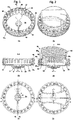
- the locator 12 sometimes called a “selector” or “localization instrument”, has the general shape of an X-axis cup. It comprises a bottom 22, extending perpendicularly to the X axis and defining upper surfaces 22. s and lower 22 i substantially flat. A window 26 is cut substantially in the center of the bottom 22.
- the window 26 has the general shape of the valve 2 seen from above and, preferably, of the accessories possibly connected to the valve, in particular an upstream reservoir and an anti-siphon device downstream.
- the dimensions of the window are adapted so as to be able to locate by palpation, through the window, the valve and said accessories, which makes it possible to position the locator in a precise position relative to the valve, even without seeing said valve.
- the axes defining the length of the window 26 and of the valve 2 constitute orientation axes O L and O V , respectively, which can thus be easily oriented parallel to each other as on figures 1 to 6 .
- Window 26 is thus a locating hole.
- reliefs 28 project from the lower surface 22 i so as to improve the positioning of the locator 12 on the valve.
- the reliefs form the footprint of the valve, which improves the immobilization of the locator relative to the valve.
- the lower surface 22i is flat, which minimizes the distance between the bottom of the locator and the valve, and therefore facilitates adjustment of the valve.
- the bottom 22 is surrounded by a cylindrical side wall 32 of axis X, which extends from the bottom 22, upwards, to the periphery of the bottom 22.
- the side wall 32 defines a housing locator 34 configured to guide the insertion of the key 16 along the X axis and the rotation around the X axis of said key.
- the side wall 32 defines a radially inner surface 32 ri and a radially outer surface 32 re .
- Guide grooves 38 extending parallel to the X axis and regularly distributed around the X axis, are formed on the radially inner surface 32 ri , for example every 15 degrees. These grooves are configured to cooperate with two elastically retractable balls, aligned along a diameter, protruding from the side surface of the key. The balls retract during the rotation of the key between two consecutive positions in which said balls enter guide grooves 38. The angular difference between two consecutive angular positions is for example 15 °. During the rotation of the key, the operator is warned by the emission of an audible click and / or by a tactile feeling caused by the engagement of the balls in the guide grooves, each time one of said angular positions is reached.
- the upper face of the side wall 32 comprises a reading zone 40 bearing position marks 42, regularly distributed around the X axis, preferably over 360 degrees around the X axis.
- the angular difference between two marks of position 42 preferably corresponds to the angular difference between two guide grooves 38.
- the position marks 42 preferably represent opening pressure values. In this case, these position marks show that the opening pressure of the valve can be set to a value between 20 and 420 mmH 2 O.
- a rotating ring 44 is mounted so as to be able to rotate about the X axis on the side wall 32.
- the rotating ring 44 carries a position mark 45 which can be placed by the operator in front of one of the position marks 42.
- the position mark 45 has thus been placed opposite the position mark "70".
- the movement of the rotating ring 44 is indexed, preferably so that the position mark 45 can only be positioned facing position marks 42.
- the indentation mechanism may be a conventional mechanism, for example. comprising an elastic tongue, the head of which, resiliently resting on the side wall 32, penetrates into corresponding housings, regularly spaced, provided on the side wall 32.
- the rotating ring 44 is preferably notched in order to facilitate its rotation by the operator.
- the reading instrument may in particular be a compass, a magnetic compass as described in EP 2 192 944 or EP 2,218,952 , or an electronic compass as described in EP 231 010 .
- the key 16 comprises an actuator 50 and an enhancer 52 of axis Y (coincident with the axis X in the figures).
- One and preferably several helical springs 54 are interposed between the booster 52 and the actuator 50 so as to oppose their approach along the Y axis.
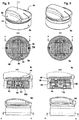
- the actuator 50 comprises a support 56 and a magnetic bar 58 of axis ⁇ 58 carrying a set of actuator magnets, and secured to the support 56 by means of a flange 59 fixed to the support 56.
- the support 56 has the general shape of a discoidal plate 60, of axis Y.
- a handle 62 protrudes from the top surface 60 seconds of the platen 60, extending radially from the Y axis.
- the handle 62 carries a magnetic orientation indicator 64 indicating the magnetic orientation of the magnetic bar 58.
- the magnetic orientation indicator 64 points to the position mark 42 giving the valve opening pressure.
- the lower surface 60 i of the plate 60 defines a housing 66 receiving the magnetic bar 58, and reliefs 67 facilitating the fixing of the flange 59 on the support 56.
- the axis ⁇ 58 and the orientation indicator magnetic 64 are preferably coplanar with the Y axis. Observation of the magnetic orientation indicator 64 thus makes it possible to determine the orientation of the magnetic bar 58 around the Y axis.
- the magnets 72 of the magnetic bar 58 are arranged to produce a magnetic field capable of moving the rotor micro-magnets of the valve in order to unlock the rotor and then to drive it in rotation.
- the arrangement of the magnets 72 must therefore be determined as a function of the position and the arrangement of the micro-magnets 6 of the rotor of the valve.
- the magnets 72 are arranged to produce a magnetic field which is maximum in the plane passing through the Y axis and containing the ⁇ 58 axis, of the magnetic bar or "maximum field plane" .
- the magnets 72 are arranged so that the magnetic field produced is symmetrical with respect to the maximum field plane and with respect to a plane perpendicular to the maximum field plane and passing through the Y axis.
- the set of magnets 72 comprises at least 1, at least 2, preferably 3 magnets whose North-South axis is radial with respect to the Y axis, called “radial magnets 72 r ”.
- the set of magnets 72 comprises at least 1, at least 2, at least 3, preferably 4 magnets whose North-South axis is parallel to the Y axis, or “longitudinal magnets” 72 l .
- each radial magnet 72 r is sandwiched between two longitudinal magnets 72 l .
- the magnets follow one another as follows: 72 l , 72 r , 72 l , 72 r (magnet centered on the Y axis), 72 l , 72 r and 72 l .
- all of the magnets 72 have a length, measured along the Y axis, which is identical.
- the width of a magnet 72, measured along the axis l'axe 58 , is smaller the closer the magnet 72 considered is to the Y axis.
- the magnets 72 are arranged in a configuration by Halbach. The inventor has discovered that this configuration is particularly effective.
- the actuator comprises a sole 74, preferably substantially cubic-rectangle, on the lower face of which the magnets 72 are fixed.
- the sole 74 is preferably metallic and preferably extends in a plane perpendicular to the Y axis, preferably along the ⁇ 58 axis of the magnetic bar.
- the sole 74 protrudes laterally from the magnets 72 so as to form two shoulders 83.
- the flange 59 is pierced by an orifice through which the magnets 72 can project from the lower surface of the flange 59.
- Angle brackets are however provided. in the surface defining said orifice so that said angles can bear on said shoulders 83.
- Each fixing screw 82 of the flange 59 on the support 56 passes through an orifice 85 of the flange 59 and is screwed into a respective bore of the support.
- Each fixing screw 82 comprises a head 84 which bears against the lower, substantially flat surface of the flange 59, so as to press the sole 74 into the housing 66.
- the fixing of the flange 59 on the support 56 however allows a translation of the support, and therefore of the magnetic bar 58 rigidly fixed on the support 56, relative to the flange 59, preferably along the axis ⁇ 58 of the magnetic bar.
- the orifice 85 is preferably of oblong section, the major axis of said section being parallel to the direction of translation ( figures 8b and 9b ). As shown on figures 8b and 9b , the head 84 then only rests on the side edges 86 of the opening through which the orifice 85 opens onto the lower surface of the flange 59.
- the booster 52 is intended to guide the translation of the actuator 50 along the Y axis.
- booster bottom 92 having the shape of a solid disk with an axis Y, and a base 94 which, upwards, ends in a skirt 96.
- the base 94 is drilled so as to define, with the bottom 92, a cavity 98 able to receive the set of magnets 72 when the actuator is pushed in along the Y axis.
- the upper surface of the base 94 further defines orifices 97 for receiving the heads 84 of the screws for fixing the flange to the support.
- the radially inner surface 96 ri of the skirt 96 and / or the lateral surface 98 l of the cavity 98 guide (s) the depression of the actuator, along the Y axis, towards the bottom of the booster 92, by engagement with the radially outer surface 59 re of the flange 59 and the side surface 72 s of the magnet assembly 72, respectively.
- the actuator is only movable in translation, along the Y axis, relative to the booster, preferably by cooperation of the side surfaces 98 l and 72 l .
- the number of springs 54 is not limited. Preferably, it is greater than 2, greater than 3, or even greater than 4, and / or less than 10.
- the springs are preferably distributed equiangularly around the axis Y. More preferably, they extend substantially. parallel to the Y axis, which maximizes their efficiency.
- each spring 54 is threaded onto a guide rod 99 fixed to the booster or to the actuator and which, when the actuator is pushed into the booster, slides in a corresponding housing provided on the actuator or the booster. , respectively, as shown in the figures 8c and 9c .
- the booster is kept integral with the actuator, for example by fixing screws 106 on the flange 59, through an orifice 108 made in the booster, as shown in the figures. figures 8c and 9c .
- the orifice 108 is preferably shaped to guide the sliding of the head 110 of the screw 106 parallel to the Y axis, while serving as a second stop for defining the high position of the actuator, as shown in Figure figure 9 .
- the helical springs 54 are interposed between the actuator 50 and the booster 52, so as to oppose the depression of the actuator in the booster. At rest, that is to say in the absence of an insertion thrust on the actuator, the springs 54 maintain the actuator at the second insertion depth (high position of the actuator shown in FIG. figure 9 ).
- the two micro-magnets of the valve rotor are spaced apart by a distance d, in a "close" position.
- this close position results from the mutual attraction of the two micro-magnets.
- the two micro-magnets preferably maintain respective rotor locking pins in cavities of the chamber, thus preventing any rotation of the rotor.
- This embodiment can for example correspond to figures 1 and 2 of EP 688 575 .
- the close position of the micro-magnets is therefore a locking position of the valve rotor.
- the valve may in particular be placed under the skin of the skull, of the neck, of the clavicular fossa, at the level of the back or of the hip.
- the actuator magnet is preferably configured to exert a magnetic field suitable for, when the valve is in the open air and the locator is arranged perpendicular to the axis of rotation of the rotor of the valve, at a distance of the valve greater than 2 mm, greater than 3 mm, greater than 5 mm, greater than 8 mm, and / or less than 30 mm, less than 25 mm, less than 20 mm, less than 15 mm, less than 12 mm, or less than 10mm, unlock the rotor at the first insertion depth and be rotatably coupled with the rotor at the second insertion depth.
- valve 2 being implanted, it extends between the valve 2 and the bottom of the locator 12. The valve is therefore not visible to the operator, who can however locate it by palpation.
- step a the operator must precisely locate valve 2 and position the locator accordingly.
- the axis of orientation Ov of the valve then extends parallel to the axis of orientation O L of the locator.
- the axis of rotation R of the rotor is then substantially coincident with the axis X of the housing of the locator.
- the axis of rotation R of the rotor can pass through the center of the valve body. It may alternatively be slightly off-center with the center of the valve body, and therefore with the longitudinal axis Ov of the valve, in particular in order to provide, between the rotor and the valve body, a space to accommodate the elastic return member. pressing the shutter. Consequently, the X axis of the locator housing may not intersect the orientation axis O L of the locator (longitudinal axis of the window 26).
- the alignment mark 43 makes it possible to orient the locator in the direction of flow of the liquid.
- An orientation of the locator relative to the valve is for example described in EP 2 192 944 .
- step b) the operator determines the angular position of the rotor of the valve around its axis with the reading instrument, for example a magnetic compass or “compass”.
- the compass is preferably inserted into the locator housing so that the axis of rotation of the compass needle is centered on the X axis of the locator housing, which itself is substantially centered on the axis of rotation R of the valve rotor.
- the compass is also used to improve the precision of the positioning of the locator so that the axis of rotation R of the rotor coincides with the axis X of the housing of the locator.
- the compass needle is then oriented along the axis ⁇ 6 of the two micro-magnets 6, radial with respect to the axis of rotation R of the rotor. On the figure 1a , it appears that the position mark 45 is now aligned with the position mark "70".
- the operator marks the axis ⁇ 6 by rotating the rotating ring 44 so as to align the position mark 45 with this axis.
- the operator can thus memorize that the opening pressure of the valve, in the initial configuration, is in this case 70 mmH 2 O.
- the following steps are intended to modify the opening pressure so that it reaches a set opening pressure of 140 mmH 2 O, for example.
- step c) the operator places the actuator so that the magnetic orientation indicator 64 is directed towards the position mark 45 “70” indicating the orientation of the axis ⁇ 6 of the micro-magnets of the valve.
- the ⁇ 58 axis of the magnetic bar is then coplanar with the ⁇ 6 axis of the micro-magnets and coplanar with the Y axis.
- the key 16 is then inserted into the locator housing, along the X axis. This insertion is guided by the contact between the radially outer surface 94 re of the base of the booster and the radially inner surface 32 ri of the side wall 32 of the booster. locator. The insertion continues until the booster comes into abutment with the bottom 22 of the locator. As shown on the figure 2b , the bottom 92 of the booster preferably rests substantially over its entire surface on the bottom 22 of the locator.
- the springs 54 then oppose the insertion of the actuator into the booster ( figure 2 ).
- the magnets 72 are too far apart to separate the micro-magnets of the rotor from one another.
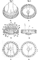
- the operator then exerts an insertion thrust, along the Y axis, in order to continue inserting the actuator into the actuator hole, by sliding on the booster, up to the first insertion depth ( arrow on the figure 3 ).
- the actuator is then in "low position".
- the first insertion depth advantageously corresponds to a maximum insertion, determined by the entry into abutment of the actuator with the booster, for example by coming into contact of the actuator with the edge 96 s of the skirt 96, and / or the upper surface 94 s of the base 94 of the booster and / or the bottom 92 of the booster and / or the bottom of the holes for receiving the heads of the fixing screws of the flange, as shown in the figure figure 3b .
- the edge of the skirt 96, the upper surface of the base 94, the bottom of the booster and the bottom of the receiving holes are examples of “first stop” determining the first insertion depth of the actuator.
- the booster could have no bottom and the magnets 72 could come into abutment with the bottom of the locator, which would then constitute a first stop determining the first insertion depth.
- the magnets 72 of the actuator are close to the micro-magnets of the rotor and exert a magnetic field strong enough for them. move away from each other.
- the distance between the two micro-magnets increases to a value D.
- the action of the micro-magnets then no longer impedes the rotation of the rotor.
- the micro-magnets thus pass from the close position ( figures 1 and 2 ), in which the rotor is locked, in a spread position ( figures 3 to 5 ), in which the rotor is unlocked.
- the operator moves the handle along the axis ⁇ 58 of the magnetic bar.
- This movement causes that of the magnets 72 of the actuator, which acts on the micro-magnets of the rotor which are coupled to them.
- the operator can thus slightly shake and, if necessary, alternately unlock the micro-magnets, which facilitates their unlocking.
- step d) the operator partially withdraws the actuator from the locator housing, up to the second insertion depth, defined by the rest position of the springs 54.
- the operator simply needs to release the pressure on the actuator. The latter then rises, under the effect of the springs 54, to the rest position shown in the figure. figure 4 , identical to the position of the figure 2 .
- the micro-magnets of the valve remain in the separated position.
- the inventor explains this phenomenon by the need to exert a higher force to separate the micro-magnets from one another (unlocking) than to maintain them in the separated position.
- the inventor has also found that, in the position of the actuator corresponding to the second insertion depth, shown in the figure. figure 4b , the rotational drive of the unlocked rotor was much more reliable than in the position of the actuator corresponding to the first insertion depth, shown in the figure. figure 3 .
- the second insertion depth of the actuator is therefore determined by the booster, which thus constitutes a “second insertion stop”.
- the assembly formed by the booster and the springs at rest also forms a guide for the rotation of the actuator 50 around the X axis, in a plane perpendicular to the X axis. Whatever the angular position of the actuator, the springs in fact oppose further insertion of the actuator.
- step e) the operator can turn the key to a position corresponding to the setpoint opening pressure, shown on the diagram. figure 5 and corresponding, for example, to 140 mmH 2 O.
- the springs 54 advantageously allow the operator to maintain the insertion depth of the actuator at the second insertion depth. Reliability is improved.
- a set of magnets 72 arranged according to a Halbach configuration advantageously allows a particularly reliable unlocking of the rotor and a drive in rotation of the rotor.
- step f) the operator moves the actuator away from the valve.
- the micro-magnets approaching forces then again become greater than the separation forces generated by the actuator, which brings them together, up to the distance d, in which they lock the rotor in rotation, as shown in figure 6 .
- the rotation of the magnetic key is indexed relative to the locator, so that the magnetic orientation indicator 64 can only be positioned facing a position mark 42.
- the indentation is determined so that, when the action of the actuator on the micro-magnets becomes weak and the micro-magnets tend to approach, the lugs are substantially in front of a cavity of the valve body and that they can penetrate into these cavities under the effect of the mutual approach of the micro-magnets.
- the actuator can be pulled out of the locator.
- the invention provides a simple and reliable solution for adjusting the opening pressure of a valve whose rotor can be locked by means of micro-magnets.
- the invention is not however limited to the embodiments described and shown, provided for illustrative purposes only.
- means other than the booster could be used to determine the first and second insertion depths.
- the booster is not necessarily integral with the actuator.
- the booster could be integrated into the locator.
- the rotation of the actuator does not cause that of the booster.
- springs 100 equivalent to springs 54 could bear directly on the locator, for example on the bottom of the locator, the booster becoming optional.
- springs are for example housed in the thickness of the side wall of the locator.
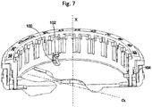
- Each spring carries a tab 102, resting on the end of the spring opposite the end resting on the locator, which protrudes inside the locator housing. The tabs thus oppose, under the effect of the springs, the insertion of the actuator beyond the second insertion depth.
- the tabs can be retracted into the bottom of the locator, which allows the first insertion depth, the magnets to be as close as possible to the valve.
- the legs are connected to each other by a circular ring 104, which is movable in an annular space, of axis X, formed in the side wall of the locator.
- the first insertion depth and / or the second insertion depth are defined by pins, for example in the form of balls, resiliently projecting from the side wall of the locator or the actuator under the effect of springs preferably extending radially with respect to the X axis.
- the pins can thus oppose a movement of the actuator, along the X axis, outside the first insertion depth and / or the second insertion depth.
- the pins can retreat into the side wall of the locator or actuator under the effect of an insertion thrust and / or an extraction pull exerted by the operator on the. actuator.
Landscapes
- Health & Medical Sciences (AREA)
- Engineering & Computer Science (AREA)
- Biomedical Technology (AREA)
- Neurology (AREA)
- Ophthalmology & Optometry (AREA)
- Otolaryngology (AREA)
- Anesthesiology (AREA)
- Heart & Thoracic Surgery (AREA)
- Hematology (AREA)
- Life Sciences & Earth Sciences (AREA)
- Animal Behavior & Ethology (AREA)
- General Health & Medical Sciences (AREA)
- Public Health (AREA)
- Veterinary Medicine (AREA)
- External Artificial Organs (AREA)
- Media Introduction/Drainage Providing Device (AREA)
Claims (12)
- Behandlungsvorrichtung, welche umfasst:- ein implantierbares Ventil, welches umfasst:- einen Körper (4), der eine innere Kammer definiert,- einen Eintrittskanal und einen Ablasskanal, die in der Seitenwand der inneren Kammer ausgebildet sind und mit einem Zuführungskatheter bzw. einem Katheter zur Drainage von Flüssigkeit verbindbar sind,- einen Rotor (5), der in der Lage ist, in der inneren Kammer um eine Drehachse (R) zu rotieren, wobei der Rotor wenigstens einen Mikromagneten (6) umfasst, der zwischen Positionen der Verriegelung und der Entriegelung des Rotors beweglich ist, in welchen er die Rotation des Rotors verhindert bzw. ermöglicht, wobei eine Rotation des Rotors den Öffnungsdruck des Ventils ändert,- ein Verschlussstück,- ein elastisches Rückstellorgan, welches das Verschlussstück in seinem Sitz zusammendrückt, um so den Durchfluss von Flüssigkeit in der inneren Kammer einzustellen und gegebenenfalls zu blockieren,- eine Vorrichtung zum Einstellen des Öffnungsdrucks des Ventils,wobei die Behandlungsvorrichtung dadurch gekennzeichnet ist, dass die Vorrichtung zum Einstellen umfasst:- einen Ventillokalisator (12), der einen Lokalisatoraufnahmeraum (34) mit einer Achse X definiert;- einen Schalter (16), der einen Aktuator (50) umfasst, der einen Aktuatormagneten (72) umfasst, wobei der Aktuator entlang der Achse X in den Lokalisatoraufnahmeraum mit einer ersten Einsetztiefe und mit einer zweiten Einsetztiefe, die kleiner als die erste Einsetztiefe ist, einsetzbar ist, wobei die Vorrichtung zum Einstellen eine Führung (52, 54) der Drehung des Aktuators um die Achse X von wenigstens einer Winkelposition des Aktuators um die Achse X aus, in welcher sich der Aktuator in der zweiten Einsetztiefe befindet, umfasst,wobei der Aktuatormagnet ein Magnetfeld erzeugt, das dafür eingerichtet ist, wenn der Lokalisator an der Haut eines Patienten anliegend angeordnet ist, unter welcher das Ventil implantiert worden ist, wobei das Ventil in einem Fenster (26) des Lokalisators angeordnet ist, in der ersten Einsetztiefe den Rotor zu entriegeln und in der zweiten Einsetztiefe mit dem Rotor drehgekoppelt zu werden.
- Behandlungsvorrichtung nach dem unmittelbar vorhergehenden Anspruch, wobei die Führung dafür ausgebildet ist, die Drehung des Aktuators um die Achse X von einer beliebigen Winkelposition des Aktuators um die Achse X aus, in welcher sich der Aktuator in der zweiten Einsetztiefe befindet, in einer Rotationsebene zu führen, die im Wesentlichen senkrecht zur Achse X ist.
- Behandlungsvorrichtung nach einem der zwei unmittelbar vorhergehenden Ansprüche, wobei die Differenz zwischen der ersten und der zweiten Einsetztiefe, entlang der Achse X gemessen, größer als 5 Millimeter ist.
- Behandlungsvorrichtung nach einem der drei unmittelbar vorhergehenden Ansprüche, welche einen ersten (96s; 94s; 92) und einen zweiten (52, 54) Anschlag umfasst, welche die erste bzw. zweite Einsetztiefe definieren.
- Behandlungsvorrichtung nach einem der vier unmittelbar vorhergehenden Ansprüche, wobei der Schalter einen Sockel (52) umfasst, auf welchem der Aktuator translatorisch bewegbar entlang einer Achse Y des Schalters angebracht ist, welche, wenn der Schalter in den Lokalisatoraufnahmeraum eingesetzt ist, mit der Achse X des Lokalisatoraufnahmeraums zusammenfällt.
- Behandlungsvorrichtung nach dem unmittelbar vorhergehenden Anspruch, welche eine Feder (54), die zwischen dem Aktuator und dem Sockel angeordnet ist, oder eine Feder (100), die zwischen dem Aktuator und dem Lokalisator angeordnet ist, umfasst, derart, dass sie einem Einsetzen des Aktuators entlang der Achse Y über die zweite Einsetztiefe hinaus entgegenwirkt.
- Behandlungsvorrichtung nach dem unmittelbar vorhergehenden Anspruch, wobei sich die eine Feder entlang einer Achse erstreckt, die zur Achse X und/oder zur Achse Y parallel ist, oder in einer Ebene, die zur Achse X oder zur Achse Y senkrecht ist.
- Behandlungsvorrichtung nach einem der zwei unmittelbar vorhergehenden Ansprüche, wobei die Feder in einem Aufnahmeraum aufgenommen ist, und auf der Seite der Öffnung des Aufnahmeraums, und so ausgebildet ist, dass sie einen Zapfen zur Achse X hin oder zur Achse Y hin drückt.
- Behandlungsvorrichtung nach einem der vier unmittelbar vorhergehenden Ansprüche, wobei der Aktuator auf dem Sockel entlang der Achse Y translatorisch geführt wird.
- Behandlungsvorrichtung nach einem der neun unmittelbar vorhergehenden Ansprüche, wobei der Aktuator eine Anordnung von Magneten (72) umfasst, die gemäß einem Halbach-Array angeordnet sind.
- Behandlungsvorrichtung nach einem der sechs unmittelbar vorhergehenden Ansprüche, wobei der Aktuator einen Halter (56), auf welchem der Aktuatormagnet (72) starr befestigt ist, einen Flansch (59), der translatorisch verschiebbar entlang der Achse Y in Bezug auf den Sockel (52) angebracht ist, und Mittel (82; 85) zum Verhindern jeder Verlagerung des Halters entlang der Achse Y in Bezug auf den Flansch bei gleichzeitigem Ermöglichen einer Verlagerung des Halters senkrecht zur Achse Y in Bezug auf den Flansch umfasst.
- Behandlungsvorrichtung nach einem der vorhergehenden Ansprüche, wobei der Aktuatormagnet dafür ausgelegt ist, ein Magnetfeld zu erzeugen, das dafür eingerichtet ist, wenn das Ventil freiliegt und wenn der Lokalisator senkrecht zur Drehachse des Rotors des Ventils angeordnet ist,- den Rotor nur zu entriegeln, wenn sich der Aktuatormagnet in einem Abstand vom Rotor befindet, der kleiner als 20 mm ist; und/oder- nur mit dem Rotor drehgekoppelt zu werden, wenn sich der Aktuatormagnet in einem Abstand vom Rotor befindet, der kleiner als 30 mm ist.
Applications Claiming Priority (2)
| Application Number | Priority Date | Filing Date | Title |
|---|---|---|---|
| FR1750840A FR3062308B1 (fr) | 2017-02-01 | 2017-02-01 | Procede de reglage d'une valve de drainage |
| PCT/EP2018/052544 WO2018141859A1 (fr) | 2017-02-01 | 2018-02-01 | Dispositif de reglage d'une valve de drainage |
Publications (2)
| Publication Number | Publication Date |
|---|---|
| EP3576830A1 EP3576830A1 (de) | 2019-12-11 |
| EP3576830B1 true EP3576830B1 (de) | 2021-06-30 |
Family
ID=58779150
Family Applications (1)
| Application Number | Title | Priority Date | Filing Date |
|---|---|---|---|
| EP18705334.3A Active EP3576830B1 (de) | 2017-02-01 | 2018-02-01 | Vorrichtung zum einstellen eines drainageventils |
Country Status (8)
| Country | Link |
|---|---|
| US (1) | US11197983B2 (de) |
| EP (1) | EP3576830B1 (de) |
| JP (1) | JP7056968B2 (de) |
| CN (1) | CN110312544B (de) |
| BR (1) | BR112019015476B1 (de) |
| ES (1) | ES2889923T3 (de) |
| FR (1) | FR3062308B1 (de) |
| WO (1) | WO2018141859A1 (de) |
Families Citing this family (3)
| Publication number | Priority date | Publication date | Assignee | Title |
|---|---|---|---|---|
| WO2000054826A1 (en) * | 1999-03-17 | 2000-09-21 | Medtronic, Inc. | Tool for adjusting an implantable adjustable fluid flow control valve |
| EP3821925B1 (de) | 2019-09-18 | 2024-03-20 | KAISHA PACKAGING Private Ltd. | Vorrichtung zum verriegeln einer kolbenstange einer spritze nach gebrauch und zum verhindern der wiederverwendung der spritze und spritzenanordnung |
| USD948714S1 (en) * | 2020-06-22 | 2022-04-12 | KAISHA PACKAGING Private Ltd. | Syringe plunger lock |
Family Cites Families (13)
| Publication number | Priority date | Publication date | Assignee | Title |
|---|---|---|---|---|
| EP0231010A3 (de) * | 1986-01-27 | 1990-10-17 | INCSTAR Corporation | Verfahren zum Immunoassay auf fester Phase une Hybridisationsassay von Nucleinsäuren und Dessin eines Teststabes und ein chromogenisches stabilisiertes Substrat |
| FR2721520B1 (fr) | 1994-06-24 | 1996-08-30 | Sophysa Sa | Valve sous-cutanée et son dispositif de réglage externe. |
| ES2297677T3 (es) * | 2004-03-27 | 2008-05-01 | CHRISTOPH MIETHKE GMBH & CO. KG | Valvula hidrocefalica ajustable. |
| ATE537868T1 (de) * | 2007-09-10 | 2012-01-15 | Sophysa Sa | Vorrichtung und verfahren zur mechanischen lokalisierung und ablesung der einstellung eines verstellbaren ventils |
| US7921571B2 (en) * | 2009-02-12 | 2011-04-12 | Sophysa | Device for mechanically locating and reading the setting of an adjustable valve |
| US8038641B2 (en) * | 2009-03-31 | 2011-10-18 | Codman & Shurtleff, Inc. | Tools and methods for programming an implantable valve |
| US8398617B2 (en) * | 2009-10-30 | 2013-03-19 | Codman & Shurtleff, Inc. | Tools and methods for programming an implantable valve |
| US8322365B2 (en) | 2010-08-17 | 2012-12-04 | Codman & Shurtleff, Inc. | Implantable adjustable valve |
| AU2012282514A1 (en) * | 2011-07-12 | 2014-01-23 | Nestec S.A. | Actuator for closing a beverage ingredient holder |
| US9242077B2 (en) | 2013-03-12 | 2016-01-26 | DePuy Synthes Products, Inc. | Dynamic adjustment tool for programming an implantable valve |
| FR3010120B1 (fr) * | 2013-09-03 | 2016-03-04 | Getinge La Calhene | Dispositif de connexion etanche entre deux volumes clos comportant des moyens de maintien prealablement a la connexion |
| FR3010636B1 (fr) | 2013-09-16 | 2015-10-02 | Sophysa Sa | Valve de drainage ajustable |
| US9216275B2 (en) * | 2013-09-30 | 2015-12-22 | DePuy Synthes Products, Inc. | Adjustable height hydrocephalus valve location device |
-
2017
- 2017-02-01 FR FR1750840A patent/FR3062308B1/fr active Active
-
2018
- 2018-02-01 ES ES18705334T patent/ES2889923T3/es active Active
- 2018-02-01 EP EP18705334.3A patent/EP3576830B1/de active Active
- 2018-02-01 WO PCT/EP2018/052544 patent/WO2018141859A1/fr not_active Ceased
- 2018-02-01 US US16/481,223 patent/US11197983B2/en active Active
- 2018-02-01 JP JP2019541276A patent/JP7056968B2/ja active Active
- 2018-02-01 BR BR112019015476-0A patent/BR112019015476B1/pt active IP Right Grant
- 2018-02-01 CN CN201880009749.9A patent/CN110312544B/zh active Active
Non-Patent Citations (1)
| Title |
|---|
| None * |
Also Published As
| Publication number | Publication date |
|---|---|
| US20190388660A1 (en) | 2019-12-26 |
| BR112019015476A2 (pt) | 2020-03-31 |
| EP3576830A1 (de) | 2019-12-11 |
| WO2018141859A1 (fr) | 2018-08-09 |
| CN110312544A (zh) | 2019-10-08 |
| BR112019015476B1 (pt) | 2024-02-06 |
| CN110312544B (zh) | 2022-01-11 |
| FR3062308B1 (fr) | 2022-01-21 |
| JP7056968B2 (ja) | 2022-04-19 |
| US11197983B2 (en) | 2021-12-14 |
| FR3062308A1 (fr) | 2018-08-03 |
| ES2889923T3 (es) | 2022-01-14 |
| JP2020505173A (ja) | 2020-02-20 |
Similar Documents
| Publication | Publication Date | Title |
|---|---|---|
| EP1567097B1 (de) | Zwischenwirbelkäfig mit mittigem verankerungsblatt | |
| EP0759124B1 (de) | Peristaltische pumpe | |
| EP3668638B1 (de) | Vorrichtung zur herstellung eines personalisierten kosmetischen produkts | |
| EP3641920B1 (de) | Vorrichtung zur herstellung eines kosmetikums | |
| ES2784750T3 (es) | Unidad de preparación de bebidas, especialmente, para máquinas de preparación de bebidas a partir de cápsulas | |
| FR3070038A1 (fr) | Dispositif de conditionnement d'objet, ensemble et procede d'extraction correspondant | |
| FR2949245A1 (fr) | Ensemble de verrou reconfigurable et procede de fonctionnement de cet ensemble | |
| WO2018141859A1 (fr) | Dispositif de reglage d'une valve de drainage | |
| CA2828733A1 (fr) | Capsule pour la preparation d'une boisson et porte-capsule adapte | |
| WO2009122030A1 (fr) | Dispositif d'iniection dans l'oeil | |
| EP2846870B1 (de) | Vorrichtung für das einsetzen von nadeln | |
| FR3112961A1 (fr) | Dispositif d’insertion d’une aiguille pour la distribution d’un produit dans un site | |
| FR2757405A1 (fr) | Aiguille de traversee de septum non carottante | |
| WO2004093944A2 (fr) | Seringue sans aiguille avec un injecteur-receptacle | |
| EP3600736B1 (de) | Spannfutter mit geneigten schiebern | |
| EP3659652A1 (de) | Vorrichtung zum entfernen von einer nadelschutzkappe | |
| FR2499883A1 (fr) | Dispositif de retenue pour poincon | |
| FR2935620A1 (fr) | Outil pour l'ebavurage de percages, avec des lames de coupe disposees par paire et un porte-outil entraine en rotation | |
| EP2184083B1 (de) | Transkraniale Befestigungsvorrichtung für Sonde zur Tiefenstimulation des Gehirns | |
| CA2839892C (fr) | Cle de serrurerie et ensemble de serrurerie a cylindre correspondant a une telle cle | |
| FR2917444A1 (fr) | Cylindre de serrure a double moyens de verrouillage | |
| FR2576775A1 (fr) | Tete de contre-angle ou de turbine d'une piece a main dentaire | |
| EP0345570A1 (de) | Spannvorrichtung für Schneideinsätze eines rotierbaren Messerkopfes zum Bearbeiten von Holz oder dergleichen | |
| EP2095905A2 (de) | Schärfvorrichtung, insbesondere für Bohrspitzen | |
| EP1660236A1 (de) | Spritzkopf für fluidprodukt |
Legal Events
| Date | Code | Title | Description |
|---|---|---|---|
| STAA | Information on the status of an ep patent application or granted ep patent |
Free format text: STATUS: UNKNOWN |
|
| STAA | Information on the status of an ep patent application or granted ep patent |
Free format text: STATUS: THE INTERNATIONAL PUBLICATION HAS BEEN MADE |
|
| PUAI | Public reference made under article 153(3) epc to a published international application that has entered the european phase |
Free format text: ORIGINAL CODE: 0009012 |
|
| STAA | Information on the status of an ep patent application or granted ep patent |
Free format text: STATUS: REQUEST FOR EXAMINATION WAS MADE |
|
| 17P | Request for examination filed |
Effective date: 20190902 |
|
| AK | Designated contracting states |
Kind code of ref document: A1 Designated state(s): AL AT BE BG CH CY CZ DE DK EE ES FI FR GB GR HR HU IE IS IT LI LT LU LV MC MK MT NL NO PL PT RO RS SE SI SK SM TR |
|
| AX | Request for extension of the european patent |
Extension state: BA ME |
|
| DAV | Request for validation of the european patent (deleted) | ||
| DAX | Request for extension of the european patent (deleted) | ||
| GRAP | Despatch of communication of intention to grant a patent |
Free format text: ORIGINAL CODE: EPIDOSNIGR1 |
|
| STAA | Information on the status of an ep patent application or granted ep patent |
Free format text: STATUS: GRANT OF PATENT IS INTENDED |
|
| RIC1 | Information provided on ipc code assigned before grant |
Ipc: A61M 27/00 20060101AFI20200818BHEP |
|
| INTG | Intention to grant announced |
Effective date: 20200914 |
|
| GRAJ | Information related to disapproval of communication of intention to grant by the applicant or resumption of examination proceedings by the epo deleted |
Free format text: ORIGINAL CODE: EPIDOSDIGR1 |
|
| STAA | Information on the status of an ep patent application or granted ep patent |
Free format text: STATUS: REQUEST FOR EXAMINATION WAS MADE |
|
| INTC | Intention to grant announced (deleted) | ||
| GRAP | Despatch of communication of intention to grant a patent |
Free format text: ORIGINAL CODE: EPIDOSNIGR1 |
|
| STAA | Information on the status of an ep patent application or granted ep patent |
Free format text: STATUS: GRANT OF PATENT IS INTENDED |
|
| INTG | Intention to grant announced |
Effective date: 20210225 |
|
| GRAS | Grant fee paid |
Free format text: ORIGINAL CODE: EPIDOSNIGR3 |
|
| GRAA | (expected) grant |
Free format text: ORIGINAL CODE: 0009210 |
|
| STAA | Information on the status of an ep patent application or granted ep patent |
Free format text: STATUS: THE PATENT HAS BEEN GRANTED |
|
| AK | Designated contracting states |
Kind code of ref document: B1 Designated state(s): AL AT BE BG CH CY CZ DE DK EE ES FI FR GB GR HR HU IE IS IT LI LT LU LV MC MK MT NL NO PL PT RO RS SE SI SK SM TR |
|
| REG | Reference to a national code |
Ref country code: CH Ref legal event code: EP |
|
| REG | Reference to a national code |
Ref country code: AT Ref legal event code: REF Ref document number: 1405768 Country of ref document: AT Kind code of ref document: T Effective date: 20210715 |
|
| REG | Reference to a national code |
Ref country code: DE Ref legal event code: R096 Ref document number: 602018019323 Country of ref document: DE |
|
| REG | Reference to a national code |
Ref country code: IE Ref legal event code: FG4D Free format text: LANGUAGE OF EP DOCUMENT: FRENCH |
|
| REG | Reference to a national code |
Ref country code: LT Ref legal event code: MG9D |
|
| PG25 | Lapsed in a contracting state [announced via postgrant information from national office to epo] |
Ref country code: FI Free format text: LAPSE BECAUSE OF FAILURE TO SUBMIT A TRANSLATION OF THE DESCRIPTION OR TO PAY THE FEE WITHIN THE PRESCRIBED TIME-LIMIT Effective date: 20210630 Ref country code: HR Free format text: LAPSE BECAUSE OF FAILURE TO SUBMIT A TRANSLATION OF THE DESCRIPTION OR TO PAY THE FEE WITHIN THE PRESCRIBED TIME-LIMIT Effective date: 20210630 Ref country code: BG Free format text: LAPSE BECAUSE OF FAILURE TO SUBMIT A TRANSLATION OF THE DESCRIPTION OR TO PAY THE FEE WITHIN THE PRESCRIBED TIME-LIMIT Effective date: 20210930 |
|
| REG | Reference to a national code |
Ref country code: NL Ref legal event code: MP Effective date: 20210630 |
|
| REG | Reference to a national code |
Ref country code: AT Ref legal event code: MK05 Ref document number: 1405768 Country of ref document: AT Kind code of ref document: T Effective date: 20210630 |
|
| PG25 | Lapsed in a contracting state [announced via postgrant information from national office to epo] |
Ref country code: SE Free format text: LAPSE BECAUSE OF FAILURE TO SUBMIT A TRANSLATION OF THE DESCRIPTION OR TO PAY THE FEE WITHIN THE PRESCRIBED TIME-LIMIT Effective date: 20210630 Ref country code: RS Free format text: LAPSE BECAUSE OF FAILURE TO SUBMIT A TRANSLATION OF THE DESCRIPTION OR TO PAY THE FEE WITHIN THE PRESCRIBED TIME-LIMIT Effective date: 20210630 Ref country code: NO Free format text: LAPSE BECAUSE OF FAILURE TO SUBMIT A TRANSLATION OF THE DESCRIPTION OR TO PAY THE FEE WITHIN THE PRESCRIBED TIME-LIMIT Effective date: 20210930 Ref country code: LV Free format text: LAPSE BECAUSE OF FAILURE TO SUBMIT A TRANSLATION OF THE DESCRIPTION OR TO PAY THE FEE WITHIN THE PRESCRIBED TIME-LIMIT Effective date: 20210630 Ref country code: GR Free format text: LAPSE BECAUSE OF FAILURE TO SUBMIT A TRANSLATION OF THE DESCRIPTION OR TO PAY THE FEE WITHIN THE PRESCRIBED TIME-LIMIT Effective date: 20211001 |
|
| REG | Reference to a national code |
Ref country code: ES Ref legal event code: FG2A Ref document number: 2889923 Country of ref document: ES Kind code of ref document: T3 Effective date: 20220114 |
|
| PG25 | Lapsed in a contracting state [announced via postgrant information from national office to epo] |
Ref country code: EE Free format text: LAPSE BECAUSE OF FAILURE TO SUBMIT A TRANSLATION OF THE DESCRIPTION OR TO PAY THE FEE WITHIN THE PRESCRIBED TIME-LIMIT Effective date: 20210630 Ref country code: SK Free format text: LAPSE BECAUSE OF FAILURE TO SUBMIT A TRANSLATION OF THE DESCRIPTION OR TO PAY THE FEE WITHIN THE PRESCRIBED TIME-LIMIT Effective date: 20210630 Ref country code: SM Free format text: LAPSE BECAUSE OF FAILURE TO SUBMIT A TRANSLATION OF THE DESCRIPTION OR TO PAY THE FEE WITHIN THE PRESCRIBED TIME-LIMIT Effective date: 20210630 Ref country code: AT Free format text: LAPSE BECAUSE OF FAILURE TO SUBMIT A TRANSLATION OF THE DESCRIPTION OR TO PAY THE FEE WITHIN THE PRESCRIBED TIME-LIMIT Effective date: 20210630 Ref country code: CZ Free format text: LAPSE BECAUSE OF FAILURE TO SUBMIT A TRANSLATION OF THE DESCRIPTION OR TO PAY THE FEE WITHIN THE PRESCRIBED TIME-LIMIT Effective date: 20210630 Ref country code: RO Free format text: LAPSE BECAUSE OF FAILURE TO SUBMIT A TRANSLATION OF THE DESCRIPTION OR TO PAY THE FEE WITHIN THE PRESCRIBED TIME-LIMIT Effective date: 20210630 Ref country code: PT Free format text: LAPSE BECAUSE OF FAILURE TO SUBMIT A TRANSLATION OF THE DESCRIPTION OR TO PAY THE FEE WITHIN THE PRESCRIBED TIME-LIMIT Effective date: 20211102 Ref country code: NL Free format text: LAPSE BECAUSE OF FAILURE TO SUBMIT A TRANSLATION OF THE DESCRIPTION OR TO PAY THE FEE WITHIN THE PRESCRIBED TIME-LIMIT Effective date: 20210630 |
|
| PG25 | Lapsed in a contracting state [announced via postgrant information from national office to epo] |
Ref country code: PL Free format text: LAPSE BECAUSE OF FAILURE TO SUBMIT A TRANSLATION OF THE DESCRIPTION OR TO PAY THE FEE WITHIN THE PRESCRIBED TIME-LIMIT Effective date: 20210630 |
|
| REG | Reference to a national code |
Ref country code: DE Ref legal event code: R097 Ref document number: 602018019323 Country of ref document: DE |
|
| PG25 | Lapsed in a contracting state [announced via postgrant information from national office to epo] |
Ref country code: DK Free format text: LAPSE BECAUSE OF FAILURE TO SUBMIT A TRANSLATION OF THE DESCRIPTION OR TO PAY THE FEE WITHIN THE PRESCRIBED TIME-LIMIT Effective date: 20210630 |
|
| PLBE | No opposition filed within time limit |
Free format text: ORIGINAL CODE: 0009261 |
|
| STAA | Information on the status of an ep patent application or granted ep patent |
Free format text: STATUS: NO OPPOSITION FILED WITHIN TIME LIMIT |
|
| PG25 | Lapsed in a contracting state [announced via postgrant information from national office to epo] |
Ref country code: AL Free format text: LAPSE BECAUSE OF FAILURE TO SUBMIT A TRANSLATION OF THE DESCRIPTION OR TO PAY THE FEE WITHIN THE PRESCRIBED TIME-LIMIT Effective date: 20210630 |
|
| 26N | No opposition filed |
Effective date: 20220331 |
|
| PG25 | Lapsed in a contracting state [announced via postgrant information from national office to epo] |
Ref country code: MC Free format text: LAPSE BECAUSE OF FAILURE TO SUBMIT A TRANSLATION OF THE DESCRIPTION OR TO PAY THE FEE WITHIN THE PRESCRIBED TIME-LIMIT Effective date: 20210630 |
|
| PG25 | Lapsed in a contracting state [announced via postgrant information from national office to epo] |
Ref country code: LU Free format text: LAPSE BECAUSE OF NON-PAYMENT OF DUE FEES Effective date: 20220201 |
|
| PG25 | Lapsed in a contracting state [announced via postgrant information from national office to epo] |
Ref country code: IE Free format text: LAPSE BECAUSE OF NON-PAYMENT OF DUE FEES Effective date: 20220201 |
|
| PG25 | Lapsed in a contracting state [announced via postgrant information from national office to epo] |
Ref country code: LT Free format text: LAPSE BECAUSE OF FAILURE TO SUBMIT A TRANSLATION OF THE DESCRIPTION OR TO PAY THE FEE WITHIN THE PRESCRIBED TIME-LIMIT Effective date: 20210630 |
|
| PG25 | Lapsed in a contracting state [announced via postgrant information from national office to epo] |
Ref country code: MK Free format text: LAPSE BECAUSE OF FAILURE TO SUBMIT A TRANSLATION OF THE DESCRIPTION OR TO PAY THE FEE WITHIN THE PRESCRIBED TIME-LIMIT Effective date: 20210630 Ref country code: CY Free format text: LAPSE BECAUSE OF FAILURE TO SUBMIT A TRANSLATION OF THE DESCRIPTION OR TO PAY THE FEE WITHIN THE PRESCRIBED TIME-LIMIT Effective date: 20210630 |
|
| PG25 | Lapsed in a contracting state [announced via postgrant information from national office to epo] |
Ref country code: HU Free format text: LAPSE BECAUSE OF FAILURE TO SUBMIT A TRANSLATION OF THE DESCRIPTION OR TO PAY THE FEE WITHIN THE PRESCRIBED TIME-LIMIT; INVALID AB INITIO Effective date: 20180201 |
|
| PG25 | Lapsed in a contracting state [announced via postgrant information from national office to epo] |
Ref country code: MT Free format text: LAPSE BECAUSE OF FAILURE TO SUBMIT A TRANSLATION OF THE DESCRIPTION OR TO PAY THE FEE WITHIN THE PRESCRIBED TIME-LIMIT Effective date: 20210630 |
|
| REG | Reference to a national code |
Ref country code: CH Ref legal event code: U11 Free format text: ST27 STATUS EVENT CODE: U-0-0-U10-U11 (AS PROVIDED BY THE NATIONAL OFFICE) Effective date: 20260301 |
|
| PGFP | Annual fee paid to national office [announced via postgrant information from national office to epo] |
Ref country code: GB Payment date: 20260219 Year of fee payment: 9 |
|
| PGFP | Annual fee paid to national office [announced via postgrant information from national office to epo] |
Ref country code: DE Payment date: 20260218 Year of fee payment: 9 |
|
| PGFP | Annual fee paid to national office [announced via postgrant information from national office to epo] |
Ref country code: BE Payment date: 20260218 Year of fee payment: 9 Ref country code: IT Payment date: 20260224 Year of fee payment: 9 |
|
| PGFP | Annual fee paid to national office [announced via postgrant information from national office to epo] |
Ref country code: FR Payment date: 20260218 Year of fee payment: 9 |
|
| PGFP | Annual fee paid to national office [announced via postgrant information from national office to epo] |
Ref country code: TR Payment date: 20260129 Year of fee payment: 9 |
|
| PGFP | Annual fee paid to national office [announced via postgrant information from national office to epo] |
Ref country code: CH Payment date: 20260301 Year of fee payment: 9 |
|
| PGFP | Annual fee paid to national office [announced via postgrant information from national office to epo] |
Ref country code: ES Payment date: 20260408 Year of fee payment: 9 |