EP3576423A1 - Haut-parleur comprenant des moyens de pré-maintien avant fixation sur une pièce réceptrice - Google Patents
Haut-parleur comprenant des moyens de pré-maintien avant fixation sur une pièce réceptrice Download PDFInfo
- Publication number
- EP3576423A1 EP3576423A1 EP19175425.8A EP19175425A EP3576423A1 EP 3576423 A1 EP3576423 A1 EP 3576423A1 EP 19175425 A EP19175425 A EP 19175425A EP 3576423 A1 EP3576423 A1 EP 3576423A1
- Authority
- EP
- European Patent Office
- Prior art keywords
- loudspeaker
- receiving part
- speaker
- receiving
- hooks
- Prior art date
- Legal status (The legal status is an assumption and is not a legal conclusion. Google has not performed a legal analysis and makes no representation as to the accuracy of the status listed.)
- Granted
Links
Images


Classifications
-
- H—ELECTRICITY
- H04—ELECTRIC COMMUNICATION TECHNIQUE
- H04R—LOUDSPEAKERS, MICROPHONES, GRAMOPHONE PICK-UPS OR LIKE ACOUSTIC ELECTROMECHANICAL TRANSDUCERS; ELECTRIC HEARING AIDS; PUBLIC ADDRESS SYSTEMS
- H04R1/00—Details of transducers, loudspeakers or microphones
- H04R1/02—Casings; Cabinets ; Supports therefor; Mountings therein
- H04R1/025—Arrangements for fixing loudspeaker transducers, e.g. in a box, furniture
-
- B—PERFORMING OPERATIONS; TRANSPORTING
- B60—VEHICLES IN GENERAL
- B60R—VEHICLES, VEHICLE FITTINGS, OR VEHICLE PARTS, NOT OTHERWISE PROVIDED FOR
- B60R11/00—Arrangements for holding or mounting articles, not otherwise provided for
- B60R11/02—Arrangements for holding or mounting articles, not otherwise provided for for radio sets, television sets, telephones, or the like; Arrangement of controls thereof
- B60R11/0217—Arrangements for holding or mounting articles, not otherwise provided for for radio sets, television sets, telephones, or the like; Arrangement of controls thereof for loud-speakers
-
- H—ELECTRICITY
- H04—ELECTRIC COMMUNICATION TECHNIQUE
- H04R—LOUDSPEAKERS, MICROPHONES, GRAMOPHONE PICK-UPS OR LIKE ACOUSTIC ELECTROMECHANICAL TRANSDUCERS; ELECTRIC HEARING AIDS; PUBLIC ADDRESS SYSTEMS
- H04R2499/00—Aspects covered by H04R or H04S not otherwise provided for in their subgroups
- H04R2499/10—General applications
- H04R2499/13—Acoustic transducers and sound field adaptation in vehicles
Definitions
- the present invention relates to the field of loudspeakers intended to be integrated especially in motor vehicles.
- the speaker assembly includes a mounting assistance structure formed by a metal hook separate from the speaker body and engaging a guide rail provided on said speaker body.
- the speaker assembly further comprises an attached fixing collar cooperating with a corresponding hole provided in the frame.
- the object of the present invention is therefore to provide a reliable system for mounting speakers on an element of the passenger compartment of a motor vehicle.
- the subject of the invention is a loudspeaker intended to be fixed on a receiving part, and comprising a loudspeaker body, for example of generally hollow cylindrical shape, more precisely in the form of a "salad bowl" delimited by a wall.
- a loudspeaker body for example of generally hollow cylindrical shape, more precisely in the form of a "salad bowl" delimited by a wall.
- front side of the passenger compartment of the vehicle a rear wall for attachment to the receiving member and a side wall connecting said front and rear walls.
- the rear wall forming a collar intended to bear on a substantially flat surface of the receiving member and comprising at least one hole for attachment to the receiving part, for example by screws, rivets or any other fastening means.
- the loudspeaker comprises at least one pre-holding hook for cooperating with the receiving part. Said hook is integral with the body of the loudspeaker.
- the loudspeaker comprises at least one support portion also integral with the loudspeaker and extending, for example horizontally, beyond the collar to the receiving part and intended to be positioned in a hole of reception of the loudspeaker provided on the receiving part.
- the body of the loudspeaker, the hook and the support portion form a single piece.
- the loudspeaker is reliably positioned relative to the receiving part so that the holes are aligned.
- the hook and the support portion form means of pre-holding the speaker on the receiving part before fixing said speaker on said receiving part.
- the hook is intended to cooperate with a corresponding lug on the receiving part.
- the hook comprises, for example, a first portion extending from an inner surface of the side wall to the receiving member and a second portion inclined relative to the first portion and extending vertically, especially downward.
- the second portion extends substantially perpendicular to the first portion.
- the loudspeaker further comprises two hooks extending on each side of the loudspeaker, parallel to each other and symmetrical with respect to the plane of symmetry of the loudspeaker.
- the two hooks are intended to cooperate respectively with a corresponding lug provided on the receiving part.
- Each hook comprises a first part extending from the inner surface to the receiving part and a second part inclined relative to the first part and extending vertically, especially downwards.
- the first part of the hooks has a shape-matching radius of curvature with a projecting edge of the receiving part and the second part extends vertically, in particular downwards and along a radius of curvature. and not strictly linear rectilinear.
- the hooks have a more fluid shape than the hooks of the previous embodiment.
- the areas of the falling edge of the receiving part on which come to cooperate the hooks have a more fluid shape, and are now more like a stall of the receiving part.
- the hooks are, for example, made of the same material as the body material of the loudspeaker.
- plastic such as for example acrylonitrile butadiene styrene, acronym "ABS”, or polypropylene or any other plastic material compatible with injection molding.
- ABS acrylonitrile butadiene styrene
- polypropylene any other plastic material compatible with injection molding.
- the loudspeaker further comprises, in the lower part, two support portions extending, for example, horizontally from the inner surface of the side wall beyond the collar towards the workpiece. receiver and intended to be positioned in a receiving port of the speaker in the receiving room.
- These support portions are symmetrical with respect to the plane of symmetry of the loudspeaker and each has an angular range of the order of 15 ° for example and without limitation.
- the bearing portions are, for example, made of the same material as the body material of the speaker.
- the support portions are, for example, interconnected, forming a sealing wall, for example, lower for protection against rainwater.
- the sealing wall makes it possible to effectively improve the sealing of the loudspeaker.
- the elements necessary for the operation of the loudspeaker are integrated in a housing mounted in the body and extending from the front wall to the rear wall, while leaving a lateral space with the side wall.
- each support portion comprises at least one substantially horizontal godron for centering the loudspeaker, so as to position the loudspeaker in XZ opposite the fixing holes of the receiving part.
- These gadroons also serve as a means of catching up games.
- the first portions of the hooks have on their outer surface at least one horizontal gadroon for centering the loudspeaker, so as to position the loudspeaker in XZ opposite the fixing holes of the loudspeaker. receiving room.
- gadroons also serve as a means of catching up games.
- the inner surface of the wall further comprises at least one structural reinforcing rib over the entire periphery of the inner surface.
- These ribs are integral with the loudspeaker body and thus form a single molded or printed part.
- the total number of ribs may be, for example, ten, and are arranged in pairs of ribs.
- the loudspeaker comprises at least one locking projection extending from the inner surface of the side wall to the receiving piece.
- the blocking projections have the function of preventing rotation of the loudspeaker during pre-hold.
- Each locking projection may be disposed between two ribs of a pair of ribs.
- the projections are integral with the body of the loudspeaker and thus form a single molded or printed part. In no way limiting, the number of projections is two. Alternatively, a different number of lock projections could be provided.
- the two projections are symmetrical with respect to the plane of symmetry of the loudspeaker.
- these locking projections may be replaced by an angular extension, for example a few degrees, of the sealing wall so as to lock the speaker in rotation during the pre-holding since the orifice 24 is not exactly circular but has lateral planarizations.
- the loudspeaker further comprises, in the lower part, a bearing portion extending horizontally from the inner surface of the front wall to the receiving part beyond the collar and intended to to be positioned in a receiving port of the speaker provided on the receiving part.
- the bearing portion is supported on a rim projecting from the rear surface of the receiving member.
- ribs and protrusions are integral with the body of the loudspeaker and thus form a single molded or printed part.
- the bore is intended to be aligned with at least one corresponding bore provided on the receiving part.
- the holes are three in number.
- the hooks, ribs, protrusions are integral with the body of the loudspeaker and thus form a single molded or printed part.
- the invention relates to a motor vehicle comprising a member of the passenger compartment forming part for fixing a speaker as described above.
- the receiving part may be, for example, a door trim, a dashboard, a rear tray, a tailgate, etc.
- a loudspeaker referenced 10 as a whole, is intended to be fixed on a receiving part 20, such as for example an element of the passenger compartment of a motor vehicle requiring assembly or removal easy and fast.
- the receiving part 20, generally sheet metal, may be, for example, a door trim, a dashboard, a rear tray, etc.
- the loudspeaker 10 comprises a loudspeaker body 12 of generally hollow cylindrical shape delimited by a front wall 13 on the side of the cockpit to be sounded by the vehicle, a rear wall 14 intended to be fixed on the receiving piece 20 and a side wall 15 connecting said front and rear walls 13, 14.
- the membrane 13a is for example made of paper, bamboo, fiberglass or flax.
- the operation of the speaker is known and will not be further described.
- the elements necessary for the operation of the loudspeaker 10 are integrated in a central housing 16 mounted in the body 12 and extending from the front wall 13 to the rear wall 14, while leaving a lateral space with the side wall 15.
- the rear wall 14 forms a flange intended to bear on a substantially planar front surface 20a of the sheet metal receiving member.
- Said flange 14 further comprises holes 14a for fixing, for example by screws, rivets (not shown), intended to be aligned with corresponding holes 20b provided on the receiving part 20.
- the holes 14a are three in number.
- the flange 14 further comprises, on its rear surface, a housing 14b (visible on the figure 3 ), adapted to receive a peripheral sealing gasket (not shown)
- Said gasket is, for example, a 5 mm thick expansive polyurethane foam deposited by points or continuously in the housing 14b and sealing between the speaker 10 and the substantially planar front surface 20a of the receiving part 20.
- the speaker 10 further comprises two hooks 18 extending on each side of the speaker and intended to cooperate respectively with a corresponding lug 22 provided on the receiving member 20.
- Each hook 18 comprises a first portion 18a extending to from the inner surface of the side wall 15 to the receiving member 20 and a second portion 18b substantially perpendicular to the first portion 18a and extending vertically downwardly.
- the two hooks 18 are parallel to each other and symmetrical with respect to the vertical plane of symmetry of the loudspeaker 10. They have been shown positioned halfway up the body of the loudspeaker nevertheless, they could also be positioned at the top of the top loudspeaker.
- the hooks 18 are integral with the body 12 of the loudspeaker and thus form a single molded part, or printed in three dimensions.
- the hooks 18 may be made of the same material as the body material of the loudspeaker or a different material.
- the hooks 18 are made of the same material as that of the body of the loudspeaker 10, provision may be made for the use of plastic, such as, for example, acrylonitrile butadiene styrene, with the acronym "ABS", or polypropylene or any other plastic material compatible with injection molding.
- plastic such as, for example, acrylonitrile butadiene styrene, with the acronym "ABS”, or polypropylene or any other plastic material compatible with injection molding.
- the hooks 18 serve to prevent the loudspeaker 10 from tilting.
- ribs 12a for reinforcing the structure all around the periphery of the inner surface of the side wall 15.
- These ribs 12a are integral with the body 12 of the loudspeaker 10 and thus form a single molded or printed part. As illustrated, and in no way limiting, the number of ribs 12a total is ten, and are arranged in pairs of ribs.
- the loudspeaker 10 further comprises, in the lower part, two bearing portions 19 (shown interconnected in the figures) extending horizontally from the inner surface of the side wall 15 to the receiving piece 20 beyond the flange 14 and intended to be positioned in an orifice 24 for receiving the speaker 10 provided on the receiving member 20.
- Support portions 19 are supported on a dropped edge 20c projecting from the rear surface 20d of the receiving member 20. This portion 19 can also be monobloc.
- the support portions 19 may also comprise, on their outer surface, horizontal gadroons 19a (visible on the figure 3 ), serving as centering means of the loudspeaker, so as to position in XZ the speaker opposite the fixing holes 20b of the receiving part 20, and means of catching games.
- the receiving orifice 24 is substantially circular, even if it has lateral "flattening" and measures for example about 16 cm in diameter.
- the lower support portions 19 are interconnected, forming a sealing wall 19b for protection against rainwater.
- This sealing wall 19b has a minimum angular range of the order of +/- 45 °.
- the sealing wall 19b shown has a wave shape but this form is optional insofar as such a form is complex to achieve in sheet metal.
- the speaker 10 is centered reliably with respect to the receiving piece 20 so that the holes 14a, 20b are aligned.
- the loudspeaker is thus in plane support on three fixing points of the loudspeaker.
- the loudspeaker 10 is mounted on the receiver 20 as follows.
- the loudspeaker 10 is positioned in the orifice 24 of the receiving part 20 until the hooks 18 engage with the corresponding lugs 22 of the receiving part 20 in sheet metal, then the loudspeaker 10 is supported by its two support portions 19 on said receiving member 20.
- the lugs 22 of the receiving part 20 are shown as quarter disc, about 1.5 cm radius, projecting from the receiving part 20 and in its same plane.
- the loudspeaker 10 can then be released before being fixed on the receiving part 20 by means of, for example, screws or rivets (not shown), inserted in the bores 14a of the flange 14 opposite the corresponding bores 20b provided on the receiving part 20. Indeed, the weight of the speaker 10 is supported by the support portions 19, in particular by the gadroons 19a, and the hooks 18 prevent its tilting.
- the pre-hold obtained thus facilitates the work of the operators, who can then take the riveter to fix the speaker without having to hold the speaker in place.
- the speaker 10 illustrated on the Figures 5 to 7 differs from the loudspeaker illustrated on the Figures 1 to 4 in particular by the shape of the hooks.
- the shape of the hooks is not limited to the shape of the hooks 18 shown on the Figures 1 to 4 .
- the loudspeaker 10 comprises two hooks 30 extending on each side of the loudspeaker and intended to cooperate respectively with zones of the receiving part 20 coming to match the shape of the fallen edge 20c of the receiving part 20.
- Each hook 30 comprises a main portion 30a extending from the inner surface of the side wall 15 to the receiving member 20.
- the main portion 30 has a radius of curvature in shape with the fallen edge 20c of the receiving member .
- Each hook further comprises a second portion 30b and extending downwards, preferably along a radius of curvature and not strictly linear rectilinear.
- the two hooks 30 are symmetrical with respect to the vertical plane of symmetry of the loudspeaker 10. They have been shown positioned halfway up the body of the loudspeaker nevertheless, they could also be positioned in the upper part of the loudspeaker. Alternatively, one could also provide a single hook in the upper central portion of the speaker.
- the hooks 30 are integral with the body 12 of the loudspeaker and thus form a single molded part, or printed in three dimensions.
- the hooks 30 may be made of the same material as the body material of the loudspeaker or a different material.
- the hooks 30 are made of the same material as that of the body of the loudspeaker 10, provision may be made for the use of plastic, such as, for example, acrylonitrile butadiene styrene, with the acronym "ABS", or polypropylene or any other plastic material compatible with injection molding.
- plastic such as, for example, acrylonitrile butadiene styrene, with the acronym "ABS”, or polypropylene or any other plastic material compatible with injection molding.
- Each of the hooks 30 may also have on their outer surface horizontal flutes 30c (visible on the figure 6 ), serving as centering means of the loudspeaker, so as to position in XZ the speaker opposite the fixing holes 20b of the receiving part 20, and means of catching games.
- the hooks 30 have a more fluid shape than the hooks 18 of the previous embodiment.
- the zones (not referenced) of the fallen edge 20c of the receiving part 20 on which cooperate the hooks 30 have a more fluid shape, and are now more like a stall of the receiving part, unlike the lugs 22 illustrated on the modes previous embodiments.
- Each hook 30 further comprises a tab 30d extending vertically in the opposite direction to the second portion 30b and serves as a structural reinforcement.
- the loudspeaker 10 further comprises two locking projections 32 extending from the inner surface 13a of the front wall 13 to the receiving part 20.
- the locking projections 32 have the function of preventing rotation of the speaker 10 during pre-hold. As illustrated, each locking projection 32 is disposed between two ribs 12a of a pair of ribs. The projections 32 are integral with the body 12 of the loudspeaker 10 and thus form a single molded or printed part. As illustrated, and in no way limiting, the number of projections 32 is two. Alternatively, a different number of locking projections 32 could be provided.
- the two projections 32 are symmetrical with respect to the vertical plane of symmetry of the loudspeaker 10.
- these locking projections may be replaced by an angular extension of a few degrees of the sealing wall 19 so as to lock the speaker in rotation during the pre-hold since the orifice 24 is not strictly circular but has lateral flattening.
- the loudspeaker 10 further comprises, in the lower part, a bearing portion 19 extending horizontally from the inner surface of the side wall to the receiving piece 20 beyond the flange 14 and intended to meet position in a receiving orifice 24 of the speaker 10 provided on the receiving member 20.
- the bearing portion 19 is supported on a dropped edge 20c projecting from the front surface 20d of the receiving member 20.
- ribs 12a and projections 32 are integral with the body 12 of the loudspeaker and thus form a single molded or printed part.
- the loudspeaker may not be mounted as shown but inclined up to 50 ° from one side or the other depending on the need for installation in the vehicle.
- the loudspeaker pre-hold hooks directly molded to the loudspeaker, no additional parts to the loudspeaker assembly are required. As soon as the loudspeaker is riveted or screwed, the hooks are no longer in contact with the sheet because the foam seal has compressed, only the contacts on the gadroons remain. These hooks only serve as pre-hold.
- the mounting of the speakers on the receiving part is facilitated, and this, by reducing the size and while improving the sealing of said speakers.
Landscapes
- Engineering & Computer Science (AREA)
- Mechanical Engineering (AREA)
- Physics & Mathematics (AREA)
- Acoustics & Sound (AREA)
- Signal Processing (AREA)
- Fittings On The Vehicle Exterior For Carrying Loads, And Devices For Holding Or Mounting Articles (AREA)
Abstract
Description
- La présente invention concerne le domaine des haut-parleurs destinés à être intégrés notamment dans les véhicules automobiles.
- Afin d'améliorer la mise en position et le maintien en position des hauts parleurs dans le véhicule automobile, il est connu de prévoir une structure de montage.
- Ainsi, pour des haut-parleurs de poids important, d'environ 900g, une telle structure de montage permet une fixation plus facile du haut-parleur.
- De plus, dû à la qualité des lèche-vitres actuels, aux découpes des vitres et à la position du haut-parleur dans la porte du véhicule, les fuites d'eau de pluie sont accrues dans le haut-parleur.
- On peut se référer à cet égard au document
JP 2007158933 - A1 - Toutefois, l'adjonction d'un crochet métallique augmente le nombre de pièces de l'ensemble haut-parleur et augmente le coût de fabrication, ainsi que le temps d'assemblage.
- On peut également se référer au document
US 2003/0019990 - A1 qui propose un support pour le montage d'un haut-parleur comportant une plaque de base et un système de guidages prévu sur une face de ladite plaque de base et dans lesquels coulisse un bord du haut-parleur. Un crochet prévu sur ladite plaque de base vient ensuite bloquer le haut-parleur. - Toutefois, une telle solution nécessite l'utilisation d'une plaque de base, ce qui augmente l'encombrement du haut-parleur et le coût de fabrication.
- Il existe un besoin d'améliorer le montage des haut-parleurs, sans augmenter l'encombrement et tout en améliorant l'étanchéité desdits haut-parleurs.
- Le but de la présente invention est donc de fournir un système fiable pour le montage de haut-parleurs sur un élément de l'habitacle d'un véhicule automobile.
- L'invention a pour objet un haut-parleur destiné à être fixé sur une pièce réceptrice, et comprenant un corps de haut-parleur, par exemple de forme générale cylindrique creux, plus précisément en forme dite de « saladier », délimité par une paroi avant du côté de l'habitacle du véhicule, une paroi arrière destinée à être fixée sur la pièce réceptrice et une paroi latérale reliant lesdites parois avant et arrière. La paroi arrière formant une collerette destinée à venir en appui sur une surface sensiblement plane de la pièce réceptrice et comprenant au moins un perçage pour la fixation sur la pièce réceptrice, par exemple par visserie, rivets ou tout autre moyen de fixation.
- Le haut-parleur comprend au moins un crochet de pré-maintien destiné à coopérer avec la pièce réceptrice. Ledit crochet est venu de matière avec le corps du haut-parleur.
- Le haut-parleur comprend au moins une portion d'appui également venue de matière avec le haut-parleur et s'étendant, par exemple horizontalement, au-delà de la collerette vers la pièce réceptrice et destinée à venir se positionner dans un orifice de réception du haut-parleur prévu sur la pièce réceptrice.
- En d'autres termes, le corps du haut-parleur, le crochet et la portion d'appui forment une seule pièce.
- Ainsi, grâce à la combinaison des crochets et des portions d'appui inférieures, le haut-parleur est positionné de manière fiable par rapport à la pièce réceptrice de manière à ce que les perçages soient alignés.
- Le crochet et la portion d'appui forment des moyens de pré-maintien du haut-parleur sur la pièce réceptrice avant la fixation dudit haut-parleur sur ladite pièce réceptrice.
- Avantageusement, le crochet est destiné à coopérer avec un ergot correspondant sur la pièce réceptrice.
- Le crochet comprend, par exemple, une première partie s'étendant à partir d'une surface intérieure de la paroi latérale vers la pièce réceptrice et une deuxième partie inclinée par rapport à la première partie et s'étendant verticalement, notamment vers le bas.
- Par exemple, la deuxième partie s'étend de manière sensiblement perpendiculaire à la première partie.
- Selon un mode de réalisation, le haut-parleur comprend en outre deux crochets s'étendant de chaque côté du haut-parleur, parallèles entre eux et symétriques par rapport au plan de symétrie du haut-parleur. Les deux crochets sont destinés à coopérer respectivement avec un ergot correspondant prévus sur la pièce réceptrice. Chaque crochet comprend une première partie s'étendant à partir de la surface intérieure vers la pièce réceptrice et une deuxième partie inclinée par rapport à la première partie et s'étendant verticalement, notamment vers le bas.
- Selon un autre mode de réalisation, la première partie des crochets a un rayon de courbure en concordance de forme avec un bord tombé en saillie de la pièce réceptrice et la deuxième partie s'étend verticalement, notamment vers le bas et selon un rayon de courbure et non de manière strictement linéaire rectiligne.
- Ainsi, les crochets ont une forme plus fluide que les crochets du mode de réalisation précédent.
- Les zones du bord tombé de la pièce réceptrice sur lesquelles viennent coopérer les crochets présentent une forme plus fluide, et s'apparentent désormais davantage à un décrochage de la pièce réceptrice.
- Les crochets sont, par exemple, réalisés dans le même matériau que le matériau du corps du haut-parleur.
- Par exemple en matière plastique, tel que par exemple de l'acrylonitrile butadiène styrène, d'acronyme « ABS », ou du polypropylène ou toute autre matière plastique compatible avec le moulage par injection.
- Selon un mode de réalisation, le haut-parleur comprend en outre, en partie inférieure, deux portions d'appui s'étendant, par exemple, horizontalement à partir de la surface intérieure de la paroi latérale au-delà de la collerette vers la pièce réceptrice et destinés à venir se positionner dans un orifice de réception du haut-parleur dans la pièce réceptrice. Ces portions d'appui sont symétriques par rapport au plan de symétrie du haut-parleur et chacune présente une plage angulaire de l'ordre de 15° par exemple et de manière non limitative.
- Les portions d'appui sont, par exemple, réalisées dans le même matériau que le matériau du corps du haut-parleur.
- Les portions d'appui sont, par exemple, reliées entre elles, formant une paroi d'étanchéité, par exemple, inférieure permettant la protection contre l'eau de pluie. La paroi d'étanchéité permet d'améliorer efficacement l'étanchéité du haut-parleur.
- Les éléments nécessaires au fonctionnement du haut-parleur sont intégrés dans un boitier monté dans le corps et s'étendant depuis la paroi avant vers la paroi arrière, tout en laissant subsister un espace latéral avec la paroi latérale.
- Selon un mode de réalisation, chaque portion d'appui comprend au moins un godron sensiblement horizontal permettant le centrage du haut-parleur, de manière à positionner en XZ le haut-parleur en face des trous de fixation de la pièce réceptrice. Ces godrons servent également de moyen de rattrapage des jeux.
- Selon un autre mode de réalisation, les premières parties des crochets comportent sur leur surface extérieure au moins un godron horizontal permettant le centrage du haut-parleur, de manière à positionner en XZ le haut-parleur en face des trous de fixation de la pièce réceptrice. Ces godrons servent également de moyen de rattrapage des jeux.
- Avantageusement, la surface intérieure de la paroi comprend en outre au moins une nervure de renforcement de structure sur toute la périphérie de la surface intérieure. Ces nervures sont venues de matière avec le corps du haut-parleur et forment ainsi une seule pièce moulée ou imprimée. Le nombre de nervures total peut être par exemple de dix, et sont agencées par paires des nervures.
- Selon un mode de réalisation, le haut-parleur comprend au moins une saillie de blocage s'étendant à partir de la surface intérieure de la paroi latérale vers la pièce réceptrice.
- Les saillies de blocage ont pour fonction d'empêcher la rotation du haut-parleur lors du pré-maintien. Chaque saillie de blocage peut être disposée entre deux nervures d'une paire de nervures. Les saillies sont venues de matière avec le corps du haut-parleur et forment ainsi une seule pièce moulée ou imprimée. De manière nullement limitative, le nombre de saillies est de deux. En variante, on pourrait prévoir un nombre différent de saillies de blocage. Les deux saillies sont symétriques par rapport au plan de symétrie du haut-parleur.
- En variante, ces saillies de blocage peuvent être remplacées par un prolongement angulaire, de quelques degrés par exemple, de la paroi d'étanchéité de manière à bloquer en rotation le haut-parleur lors du pré-maintien puisque l'orifice 24 n'est pas exactement circulaire mais présente des aplanissements latéraux.
- Selon un autre mode de réalisation, le haut-parleur comprend en outre, en partie inférieure, une portion d'appui s'étendant horizontalement à partir de la surface intérieure de la paroi avant vers la pièce réceptrice au-delà de la collerette et destinés à venir se positionner dans un orifice de réception du haut-parleur prévu sur la pièce réceptrice. La portion d'appui est en appui sur un bord tombé en saillie de la surface arrière de la pièce réceptrice.
- Ces nervures et saillies sont venues de matière avec le corps du haut-parleur et forment ainsi une seule pièce moulée ou imprimée.
- Le perçage est destiné à être aligné avec au moins un perçage correspondant prévu sur la pièce réceptrice.
- Par exemple, les perçages sont au nombre de trois.
- Les crochets, nervures, saillies sont venues de matière avec le corps du haut-parleur et forment ainsi une seule pièce moulée ou imprimée.
- Selon un deuxième aspect, l'invention concerne un véhicule automobile comprenant un élément de l'habitacle formant pièce réceptrice pour la fixation d'un haut-parleur tel que décrit précédemment.
- La pièce réceptrice peut être, par exemple, une garniture de porte, un tableau de bord, un plateau arrière, un hayon arrière, etc...
- D'autres buts, caractéristiques et avantages de l'invention apparaîtront à la lecture de la description suivante, donnée uniquement à titre d'exemple non limitatif, et faite en référence aux dessins annexés sur lesquels :
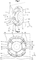
- la
figure 1 représente une vue en perspective d'un haut-parleur selon un premier mode de réalisation de l'invention monté sur une pièce réceptrice ; - la
figure 2 illustre une vue de derrière du haut-parleur selon lafigure 1 ; - la
figure 3 illustre une vue de dessous du haut-parleur selon lafigure 1 ; - la
figure 4 représente une vue en perspective d'un haut-parleur selon un autre mode de réalisation de l'invention monté sur une pièce réceptrice. - la
figure 5 représente une vue de derrière d'un haut-parleur monté sur une pièce réceptrice selon un autre mode de réalisation ; et - les
figures 6 et 7 illustrent des détails du haut-parleur et de la pièce réceptrice de lafigure 5 . - Tel qu'illustré sur les
figures 1 à 3 , un haut-parleur, référencé 10 dans son ensemble, est destiné à être fixé sur une pièce réceptrice 20, telle que par exemple un élément de l'habitacle d'un véhicule automobile nécessitant un montage ou un retrait facile et rapide. La pièce réceptrice 20, généralement en tôle, peut être, par exemple, une garniture de porte, un tableau de bord, un plateau arrière, etc... - Le haut-parleur 10 comprend un corps 12 de haut-parleur de forme générale cylindrique creux délimité par une paroi avant 13 du côté de l'habitacle à sonoriser du véhicule, une paroi arrière 14 destinée à être fixée sur la pièce réceptrice 20 et une paroi latérale 15 reliant lesdites parois avant et arrière 13, 14. La membrane 13a est par exemple constituée de papier, de bambou, de fibre de verre ou encore de lin.
- Le fonctionnement du haut-parleur est connu et ne sera pas davantage décrit. Les éléments nécessaires au fonctionnement du haut-parleur 10 sont intégrés dans un boitier 16 central monté dans le corps 12 et s'étendant depuis la paroi avant 13 vers la paroi arrière 14, tout en laissant subsister un espace latéral avec la paroi latérale 15.
- La paroi arrière 14 forme une collerette destinée à venir en appui sur une surface avant sensiblement plane 20a de la pièce réceptrice en tôle. Ladite collerette 14 comprend en outre des perçages 14a pour la fixation, par exemple par visserie, rivets (non représentés), destinés à être alignés avec des perçages correspondants 20b prévus sur la pièce réceptrice 20. Tel qu'illustré, et à titre nullement limitatif, les perçages 14a sont au nombre de trois.
- La collerette 14 comprend en outre, sur sa surface arrière, un logement 14b (visible sur la
figure 3 ), adapté à recevoir un joint périphérique d'étanchéité (non représenté. Ledit joint est, par exemple, une mousse de polyuréthane expansive de 5 mm d'épaisseur déposée par points ou en continu dans le logement 14b et assurant l'étanchéité entre le haut-parleur 10 et la surface avant sensiblement plane 20a de la pièce réceptrice 20. - Le haut-parleur 10 comprend en outre deux crochets 18 s'étendant de chaque côté du haut-parleur et destinés à coopérer respectivement avec un ergot 22 correspondant prévu sur la pièce réceptrice 20. Chaque crochet 18 comprend une première partie 18a s'étendant à partir de la surface intérieure de la paroi latérale 15 vers la pièce réceptrice 20 et une deuxième partie 18b sensiblement perpendiculaire à la première partie 18a et s'étendant verticalement, vers le bas.
- Les deux crochets 18 sont parallèles entre eux et symétriques par rapport au plan de symétrie vertical du haut-parleur 10. Ils ont été représentés positionnés à mi-hauteur du corps du haut-parleur néanmoins, ils pourraient aussi être positionnés en partie supérieure du haut-parleur.
- En variante, on pourrait également prévoir un unique crochet et son ergot afférent en partie centrale supérieure du haut-parleur.
- Les crochets 18 sont venus de matière avec le corps 12 du haut-parleur et forment ainsi une seule pièce moulée, ou imprimée en trois dimensions.
- Les crochets 18 peuvent être réalisés dans le même matériau que le matériau du corps du haut-parleur ou dans un matériau différent. Par exemple, lorsque les crochets 18 sont réalisés dans le même matériau que celui du corps du haut-parleur 10, on peut prévoir l'utilisation du plastique, tel que par exemple de l'acrylonitrile butadiène styrène, d'acronyme « ABS », ou du polypropylène ou toute autre matière plastique compatible avec le moulage par injection.
- Les crochets 18 ont pour fonction d'empêcher le basculement du haut-parleur 10. Entre le boitier central 16 et la paroi latérale 15 intérieure sont disposées des nervures 12a de renforcement de structure sur toute la périphérie de la surface intérieure de la paroi latérale 15. Ces nervures 12a sont venues de matière avec le corps 12 du haut-parleur 10 et forment ainsi une seule pièce moulée ou imprimée. Tel qu'illustré, et de manière nullement limitative, le nombre de nervures 12a total est de dix, et sont agencées par paires des nervures.
- Le haut-parleur 10 comprend en outre, en partie inférieure, deux portions d'appui 19 (représentées reliées entre elles sur les figures) s'étendant horizontalement à partir de la surface intérieure de la paroi latérale 15 vers la pièce réceptrice 20 au-delà de la collerette 14 et destinés à venir se positionner dans un orifice 24 de réception du haut-parleur 10 prévu sur la pièce réceptrice 20. Les portions d'appui 19 sont en appui sur un bord tombé 20c en saillie de la surface arrière 20d de la pièce réceptrice 20. Cette partie 19 peut être également monobloc. Les portions d'appui 19 peuvent également comporter, sur leur surface extérieure, des godrons horizontaux 19a (visibles sur la
figure 3 ), servant de moyen de centrage du haut-parleur, de manière à positionner en XZ le haut-parleur en face des trous de fixation 20b de la pièce réceptrice 20, ainsi que de moyen de rattrapage des jeux. - L'orifice 24 de réception est sensiblement circulaire, même s'il présente des « aplanissements » latéraux, et mesure par exemple environ 16 cm de diamètre.
- Tel qu'illustré, les portions d'appui inférieures 19 sont reliées entre elles, formant une paroi d'étanchéité 19b permettant la protection contre l'eau de pluie. Cette paroi d'étanchéité 19b présente une plage angulaire minimum de l'ordre de +/-45°. La paroi d'étanchéité 19b représentée a une forme de vague mais cette forme est optionnelle dans la mesure où une telle forme est complexe à réaliser en tôlerie.
- En variante, on pourrait ne pas prévoir une telle paroi d'étanchéité 19b, tel qu'illustré dans le mode de réalisation de la
figure 4 dans lequel les mêmes éléments portent les mêmes références, on conserverait alors deux portions d'appui inférieures 19 distinctes non reliées entre elles, et pourvues chacune d'un ou de plusieurs godrons 19a de centrage. - Grâce à la combinaison des crochets 18 et des portions d'appui inférieures 19 et de leurs godrons de centrage 19a, le haut-parleur 10 est centré de manière fiable par rapport à la pièce réceptrice 20 de manière à ce que les perçages 14a, 20b soient alignés.
- Le haut-parleur est ainsi en appui-plan sur trois points de fixation du haut-parleur.
- Le haut-parleur 10 est monté sur la pièce réceptrice 20 comme suit. Le haut-parleur 10 est positionné dans l'orifice 24 de la pièce réceptrice 20 jusqu'à engagement des crochets 18 avec les ergots 22 correspondants de la pièce réceptrice 20 en tôle, puis le haut-parleur 10 vient en appui via ses deux portions d'appui 19 sur ladite pièce réceptrice 20. Les ergots 22 de la pièce réceptrice 20 sont représentés comme des quarts de disque, d'environ 1,5 cm de rayon, en saillie de la pièce réceptrice 20 et dans son même plan.
- Le haut-parleur 10 peut ensuite être relâché avant d'être fixé sur la pièce réceptrice 20 au moyen par exemple de vis ou de rivets (non représentés), insérés dans les perçages 14a de la collerette 14 en regard des perçages correspondants 20b prévu sur la pièce réceptrice 20. En effet, le poids du haut-parleur 10 est soutenu par les portions d'appui 19, notamment par les godrons 19a, et les crochets 18 permettent d'éviter son basculement.
- Les crochets 18 de pré-maintien, de même que la paroi d'étanchéité 19b, étant intégrés au haut-parleur, ils ne constituent pas des pièces supplémentaires et leur forme permet un démoulage facile, sans avoir à ajouter un tiroir dans le moule. Le pré-maintien obtenu facilite ainsi le travail des opérateurs, qui peuvent alors prendre la riveteuse pour fixer le haut-parleur sans avoir à tenir le haut-parleur en place.
- Le haut-parleur 10 illustré sur les
figures 5 à 7 , dans lesquelles les mêmes éléments portent les mêmes références, diffère du haut-parleur illustré sur lesfigures 1 à 4 notamment par la forme des crochets. - En effet, la forme des crochets n'est pas limitée à la forme des crochets 18 représentés sur les
figures 1 à 4 . - Dans le mode de réalisation des
figures 5 à 7 , le haut-parleur 10 comprend deux crochets 30 s'étendant de chaque côté du haut-parleur et destinés à coopérer respectivement avec des zones de la pièce réceptrice 20 en venant épouser la forme du bord tombé 20c de la pièce réceptrice 20. - Chaque crochet 30 comprend une partie principale 30a s'étendant à partir de la surface intérieure de la paroi latérale 15 vers la pièce réceptrice 20. La partie principale 30 a un rayon de courbure en concordance de forme avec le bord tombé 20c de la pièce réceptrice.
- Chaque crochet comprend en outre une deuxième partie 30b et s'étendant, vers le bas, préférentiellement selon un rayon de courbure et non de manière strictement linéaire rectiligne.
- Les deux crochets 30 sont symétriques par rapport au plan de symétrie vertical du haut-parleur 10. Ils ont été représentés positionnés à mi-hauteur du corps du haut-parleur néanmoins, ils pourraient aussi être positionnés en partie supérieure du haut-parleur. En variante, on pourrait également prévoir un unique crochet en partie centrale supérieure du haut-parleur.
- Les crochets 30 sont venus de matière avec le corps 12 du haut-parleur et forment ainsi une seule pièce moulée, ou imprimée en trois dimensions.
- Les crochets 30 peuvent être réalisés dans le même matériau que le matériau du corps du haut-parleur ou dans un matériau différent. Par exemple, lorsque les crochets 30 sont réalisés dans le même matériau que celui du corps du haut-parleur 10, on peut prévoir l'utilisation du plastique, tel que par exemple de l'acrylonitrile butadiène styrène, d'acronyme « ABS », ou du polypropylène ou toute autre matière plastique compatible avec le moulage par injection.
- Chacun des crochets 30 peut également comporter sur leur surface extérieure des godrons horizontaux 30c (visibles sur la
figure 6 ), servant de moyen de centrage du haut-parleur, de manière à positionner en XZ le haut-parleur en face des trous de fixation 20b de la pièce réceptrice 20, ainsi que de moyen de rattrapage des jeux. - Ainsi, les crochets 30 ont une forme plus fluide que les crochets 18 du mode de réalisation précédent.
- Les zones (non référencées) du bord tombé 20c de la pièce réceptrice 20 sur lesquelles viennent coopérer les crochets 30 présentent une forme plus fluide, et s'apparentent désormais davantage à un décrochage de la pièce réceptrice, contrairement aux ergots 22 illustrés sur les modes de réalisation précédents.
- Chaque crochet 30 comprend en outre une patte 30d s'étendant verticalement dans la direction opposée à la deuxième partie 30b et sert de renfort structurel.
- Le haut-parleur 10 comprend en outre deux saillies de blocage 32 s'étendant à partir de la surface intérieure 13a de la paroi avant 13 vers la pièce réceptrice 20.
- Les saillies de blocage 32 ont pour fonction d'empêcher la rotation du haut-parleur 10 lors du pré-maintien. Tel qu'illustré, chaque saillie de blocage 32 est disposée entre deux nervures 12a d'une paire de nervures. Les saillies 32 sont venues de matière avec le corps 12 du haut-parleur 10 et forment ainsi une seule pièce moulée ou imprimée. Tel qu'illustré, et de manière nullement limitative, le nombre de saillies 32 est de deux. En variante, on pourrait prévoir un nombre différent de saillies de blocage 32.
- Les deux saillies 32 sont symétriques par rapport au plan de symétrie vertical du haut-parleur 10.
- En variante, ces saillies de blocage peuvent être remplacées par un prolongement angulaire de quelques degrés de la paroi d'étanchéité 19 de manière à bloquer en rotation le haut-parleur lors du pré-maintien puisque l'orifice 24 n'est pas strictement circulaire mais présente des aplanissements latéraux.
- Le haut-parleur 10 comprend en outre, en partie inférieure, une portion d'appui 19 s'étendant horizontalement à partir de la surface intérieure de la paroi latérale vers la pièce réceptrice 20 au-delà de la collerette 14 et destinés à venir se positionner dans un orifice 24 de réception du haut-parleur 10 prévu sur la pièce réceptrice 20. La portion d'appui 19 est en appui sur un bord tombé 20c en saillie de la surface avant 20d de la pièce réceptrice 20.
- Ces nervures 12a et saillies 32 sont venues de matière avec le corps 12 du haut-parleur et forment ainsi une seule pièce moulée ou imprimée.
- En cas de besoin le haut- parleur peut ne pas être monté tel que représenté mais incliné jusqu'à 50° d'un côté ou de l'autre en fonction des besoins d'implantation dans le véhicule.
- Grâce aux crochets de pré-maintien du haut-parleur intégrés directement par moulage audit haut-parleur, aucune pièce supplémentaire au montage du haut-parleur n'est nécessaire. Dès que le haut-parleur est riveté ou vissé, les crochets ne sont plus en contact avec la tôle car le joint en mousse s'est comprimé, seuls les contacts sur les godrons demeurent. Ces crochets ne servent que de pré-maintien.
- Le montage des haut-parleurs sur la pièce réceptrice est facilité, et ce, en diminuant l'encombrement et tout en améliorant l'étanchéité desdits haut-parleurs.
Claims (10)
- Haut-parleur (10) destiné à être fixé sur une pièce réceptrice (20), et comprenant un corps (12) de haut-parleur, délimité par une paroi avant (13), une paroi arrière (14) destinée à être fixée sur la pièce réceptrice (20) et une paroi latérale (15) reliant lesdites parois avant et arrière (13, 14), la paroi arrière (14) formant une collerette destinée à venir en appui sur la pièce réceptrice (20) et comprenant au moins un perçage (14a) pour la fixation sur la pièce réceptrice (20), caractérisé en ce que le haut-parleur (10) comprend au moins un crochet (18, 30) de pré-maintien destiné à coopérer avec la pièce réceptrice (20), ledit crochet (18, 30) étant venu de matière avec le corps (12) du haut-parleur (10) et en ce que le haut-parleur (10) comprend au moins une portion d'appui (19) s'étendant au-delà de la collerette (14) vers la pièce réceptrice (20) et destinée à venir se centrer dans un orifice (24) de réception du haut-parleur (10) prévu sur la pièce réceptrice (20).
- Haut-parleur selon la revendication 1, dans lequel le crochet (18, 30) comprend une première partie (18a, 30a) s'étendant à partir d'une surface intérieure de la paroi latérale (15) vers la pièce réceptrice (20) et une deuxième partie (18b, 30b) inclinée par rapport à la première partie (18a, 30a) et s'étendant verticalement, notamment vers le bas.
- Haut-parleur selon la revendication 1 ou 2, comprenant en outre deux crochets (18, 30) s'étendant de chaque côté du haut-parleur, parallèles entre eux et symétriques par rapport au plan de symétrie du haut-parleur (10).
- Haut-parleur selon l'une quelconque des revendications 2 à 3, dans lequel la première partie (30a) des crochets (30) a un rayon de courbure en concordance de forme avec un bord tombé (20c) en saillie de la surface arrière de la pièce réceptrice (20) et la deuxième partie (30b) s'étend verticalement, notamment vers le bas et selon un rayon de courbure.
- Haut-parleur selon l'une quelconque des revendications précédentes, dans lequel les crochets (18, 30) sont réalisés dans le même matériau que le matériau du corps du haut-parleur.
- Haut-parleur selon l'une quelconque des revendications précédentes, comprenant en outre deux portions d'appui (19) s'étendant, par exemple horizontalement, à partir de la surface intérieure de la paroi latérale (15) au-delà de la collerette (14) vers la pièce réceptrice (20) et destinées à venir se positionner dans un orifice (24) de réception du haut-parleur (10) prévu sur la pièce de réception (20).
- Haut-parleur selon la revendication 5, dans lequel les portions d'appui (19) sont reliées par une paroi d'étanchéité (19b).
- Haut-parleur selon la revendication 6 ou 7, dans lequel chaque portion d'appui (19) comprend au moins un godron sensiblement horizontal (19a) permettant le centrage du haut-parleur.
- Haut-parleur selon l'une quelconque des revendications 2 à 7, dans lequel les premières parties (30a) des crochets (30) comportent sur leur surface extérieure au moins un godron sensiblement horizontal (30c) permettant le centrage du haut-parleur.
- Haut-parleur selon l'une quelconque des revendications précédentes, comprenant au moins une saillie de blocage (32) s'étendant à partir de la surface intérieure de la paroi latérale (15) vers la pièce réceptrice (20).
Applications Claiming Priority (1)
| Application Number | Priority Date | Filing Date | Title |
|---|---|---|---|
| FR1854705A FR3082086B1 (fr) | 2018-05-31 | 2018-05-31 | Haut-parleur comprenant des moyens de pre-maintien avant fixation sur une piece receptrice |
Publications (2)
| Publication Number | Publication Date |
|---|---|
| EP3576423A1 true EP3576423A1 (fr) | 2019-12-04 |
| EP3576423B1 EP3576423B1 (fr) | 2021-04-21 |
Family
ID=62816839
Family Applications (1)
| Application Number | Title | Priority Date | Filing Date |
|---|---|---|---|
| EP19175425.8A Active EP3576423B1 (fr) | 2018-05-31 | 2019-05-20 | Haut-parleur comprenant des moyens de pré-maintien avant fixation sur une pièce réceptrice |
Country Status (2)
| Country | Link |
|---|---|
| EP (1) | EP3576423B1 (fr) |
| FR (1) | FR3082086B1 (fr) |
Cited By (1)
| Publication number | Priority date | Publication date | Assignee | Title |
|---|---|---|---|---|
| CN114650487A (zh) * | 2020-12-18 | 2022-06-21 | 李尔公司 | 带有扬声器保持支架的衬垫 |
Citations (4)
| Publication number | Priority date | Publication date | Assignee | Title |
|---|---|---|---|---|
| US20030019990A1 (en) | 2001-07-26 | 2003-01-30 | Takehiro Co., Ltd. And Nagase & Co., Ltd. | Bracket for mounting speaker |
| JP2007158933A (ja) | 2005-12-07 | 2007-06-21 | Fujitsu Ten Ltd | スピーカユニット |
| FR2908710A1 (fr) * | 2006-11-22 | 2008-05-23 | Renault Sas | Dispositif de fixation d'un haut-parleur sur un panneau de vehicule |
| EP2332783A1 (fr) * | 2009-12-09 | 2011-06-15 | Peugeot Citroën Automobiles SA | Dispositif de fixation d'un équipement, à moyens d'immobilisation propres à s'auto-bloquer dans des ouvertures d'une paroi |
-
2018
- 2018-05-31 FR FR1854705A patent/FR3082086B1/fr active Active
-
2019
- 2019-05-20 EP EP19175425.8A patent/EP3576423B1/fr active Active
Patent Citations (4)
| Publication number | Priority date | Publication date | Assignee | Title |
|---|---|---|---|---|
| US20030019990A1 (en) | 2001-07-26 | 2003-01-30 | Takehiro Co., Ltd. And Nagase & Co., Ltd. | Bracket for mounting speaker |
| JP2007158933A (ja) | 2005-12-07 | 2007-06-21 | Fujitsu Ten Ltd | スピーカユニット |
| FR2908710A1 (fr) * | 2006-11-22 | 2008-05-23 | Renault Sas | Dispositif de fixation d'un haut-parleur sur un panneau de vehicule |
| EP2332783A1 (fr) * | 2009-12-09 | 2011-06-15 | Peugeot Citroën Automobiles SA | Dispositif de fixation d'un équipement, à moyens d'immobilisation propres à s'auto-bloquer dans des ouvertures d'une paroi |
Cited By (1)
| Publication number | Priority date | Publication date | Assignee | Title |
|---|---|---|---|---|
| CN114650487A (zh) * | 2020-12-18 | 2022-06-21 | 李尔公司 | 带有扬声器保持支架的衬垫 |
Also Published As
| Publication number | Publication date |
|---|---|
| FR3082086B1 (fr) | 2020-05-22 |
| FR3082086A1 (fr) | 2019-12-06 |
| EP3576423B1 (fr) | 2021-04-21 |
Similar Documents
| Publication | Publication Date | Title |
|---|---|---|
| EP2612489B1 (fr) | Support pour terminal mobile pouvant recevoir des terminaux mobiles de différente dimensions | |
| EP3149433B1 (fr) | Agencement de montage d'un organe fonctionnel tel qu'une camera sur un element de carrosserie d'un vehicule automobile | |
| FR3071296A1 (fr) | Dispositif d'etancheite pour organe de dialogue homme-machine | |
| EP3313716B1 (fr) | Dispositif de fixation destiné à être monté dans une cuvette, typiquement de roue de secours, d'un plancher, notamment arrière, de véhicule automobile | |
| EP3576423B1 (fr) | Haut-parleur comprenant des moyens de pré-maintien avant fixation sur une pièce réceptrice | |
| FR3076509A1 (fr) | Dispositif d’attache et de guidage pour faisceaux electriques cheminant entre un longeron et sa garniture d’habillage. | |
| WO2019234318A1 (fr) | Module microphone destine a etre monte sur une garniture de pavillon d'un vehicule automobile | |
| WO2017006011A1 (fr) | Projecteur avant de véhicule automobile muni d'un boîtier comportant un élément d'ancrage inférieur | |
| EP4294677B1 (fr) | Élément de fond de coffre de véhicule automobile | |
| FR3099907A1 (fr) | Déflecteur aérodynamique arrière pour véhicule automobile | |
| FR3111598A1 (fr) | Capot de support d’alarme | |
| EP4433329B1 (fr) | Système de montage en rotation d'une tablette de recouvrement d'un compartiment à bagages de véhicule automobile | |
| FR3067690B1 (fr) | Vehicule automobile equipe d’une console centrale contenant des boitiers electroniques | |
| EP3953214B1 (fr) | Dispositif de vide-poche de garnissage de portière de véhicule | |
| FR3014791A1 (fr) | Systeme de securite pour vehicule | |
| EP3892010B1 (fr) | Piece de rigidification pour caisson d'enceinte acoustique | |
| EP2076407B1 (fr) | Piece d'interface pour le montage d'un element dans une ouverture d'une platine | |
| FR3128673A1 (fr) | Support pour un objet électronique. | |
| FR3102960A1 (fr) | Dispositif de fixation d’un boîtier de communication dans un véhicule automobile et méthode de fixation | |
| EP4561867A1 (fr) | Dispositif de support multifonction pour calandre de véhicule | |
| FR3094938A1 (fr) | Console de pavillon pour véhicule automobile | |
| FR2677593A1 (fr) | Reducteur de format de decoupe pour autoradio sur les tableaux de bord de vehicules. | |
| FR2941202A1 (fr) | Ensemble de carrosserie comprenant des moyens de fixation d'un element optique. | |
| FR3096004A1 (fr) | aménagement de parechoc pour véhicule automobile | |
| FR3063944A1 (fr) | Garniture de seuil de panneau lateral de brisement d’un vehicule automobile |
Legal Events
| Date | Code | Title | Description |
|---|---|---|---|
| PUAI | Public reference made under article 153(3) epc to a published international application that has entered the european phase |
Free format text: ORIGINAL CODE: 0009012 |
|
| STAA | Information on the status of an ep patent application or granted ep patent |
Free format text: STATUS: THE APPLICATION HAS BEEN PUBLISHED |
|
| AK | Designated contracting states |
Kind code of ref document: A1 Designated state(s): AL AT BE BG CH CY CZ DE DK EE ES FI FR GB GR HR HU IE IS IT LI LT LU LV MC MK MT NL NO PL PT RO RS SE SI SK SM TR |
|
| AX | Request for extension of the european patent |
Extension state: BA ME |
|
| STAA | Information on the status of an ep patent application or granted ep patent |
Free format text: STATUS: REQUEST FOR EXAMINATION WAS MADE |
|
| STAA | Information on the status of an ep patent application or granted ep patent |
Free format text: STATUS: EXAMINATION IS IN PROGRESS |
|
| 17P | Request for examination filed |
Effective date: 20200427 |
|
| RBV | Designated contracting states (corrected) |
Designated state(s): AL AT BE BG CH CY CZ DE DK EE ES FI FR GB GR HR HU IE IS IT LI LT LU LV MC MK MT NL NO PL PT RO RS SE SI SK SM TR |
|
| 17Q | First examination report despatched |
Effective date: 20200604 |
|
| GRAP | Despatch of communication of intention to grant a patent |
Free format text: ORIGINAL CODE: EPIDOSNIGR1 |
|
| STAA | Information on the status of an ep patent application or granted ep patent |
Free format text: STATUS: GRANT OF PATENT IS INTENDED |
|
| INTG | Intention to grant announced |
Effective date: 20210127 |
|
| GRAS | Grant fee paid |
Free format text: ORIGINAL CODE: EPIDOSNIGR3 |
|
| GRAA | (expected) grant |
Free format text: ORIGINAL CODE: 0009210 |
|
| STAA | Information on the status of an ep patent application or granted ep patent |
Free format text: STATUS: THE PATENT HAS BEEN GRANTED |
|
| AK | Designated contracting states |
Kind code of ref document: B1 Designated state(s): AL AT BE BG CH CY CZ DE DK EE ES FI FR GB GR HR HU IE IS IT LI LT LU LV MC MK MT NL NO PL PT RO RS SE SI SK SM TR |
|
| REG | Reference to a national code |
Ref country code: GB Ref legal event code: FG4D Free format text: NOT ENGLISH |
|
| REG | Reference to a national code |
Ref country code: CH Ref legal event code: EP |
|
| REG | Reference to a national code |
Ref country code: DE Ref legal event code: R096 Ref document number: 602019004004 Country of ref document: DE Ref country code: IE Ref legal event code: FG4D Free format text: LANGUAGE OF EP DOCUMENT: FRENCH |
|
| REG | Reference to a national code |
Ref country code: AT Ref legal event code: REF Ref document number: 1385873 Country of ref document: AT Kind code of ref document: T Effective date: 20210515 |
|
| REG | Reference to a national code |
Ref country code: LT Ref legal event code: MG9D |
|
| REG | Reference to a national code |
Ref country code: AT Ref legal event code: MK05 Ref document number: 1385873 Country of ref document: AT Kind code of ref document: T Effective date: 20210421 |
|
| REG | Reference to a national code |
Ref country code: NL Ref legal event code: MP Effective date: 20210421 |
|
| PG25 | Lapsed in a contracting state [announced via postgrant information from national office to epo] |
Ref country code: HR Free format text: LAPSE BECAUSE OF FAILURE TO SUBMIT A TRANSLATION OF THE DESCRIPTION OR TO PAY THE FEE WITHIN THE PRESCRIBED TIME-LIMIT Effective date: 20210421 Ref country code: LT Free format text: LAPSE BECAUSE OF FAILURE TO SUBMIT A TRANSLATION OF THE DESCRIPTION OR TO PAY THE FEE WITHIN THE PRESCRIBED TIME-LIMIT Effective date: 20210421 Ref country code: FI Free format text: LAPSE BECAUSE OF FAILURE TO SUBMIT A TRANSLATION OF THE DESCRIPTION OR TO PAY THE FEE WITHIN THE PRESCRIBED TIME-LIMIT Effective date: 20210421 Ref country code: NL Free format text: LAPSE BECAUSE OF FAILURE TO SUBMIT A TRANSLATION OF THE DESCRIPTION OR TO PAY THE FEE WITHIN THE PRESCRIBED TIME-LIMIT Effective date: 20210421 Ref country code: AT Free format text: LAPSE BECAUSE OF FAILURE TO SUBMIT A TRANSLATION OF THE DESCRIPTION OR TO PAY THE FEE WITHIN THE PRESCRIBED TIME-LIMIT Effective date: 20210421 Ref country code: BG Free format text: LAPSE BECAUSE OF FAILURE TO SUBMIT A TRANSLATION OF THE DESCRIPTION OR TO PAY THE FEE WITHIN THE PRESCRIBED TIME-LIMIT Effective date: 20210721 |
|
| PG25 | Lapsed in a contracting state [announced via postgrant information from national office to epo] |
Ref country code: GR Free format text: LAPSE BECAUSE OF FAILURE TO SUBMIT A TRANSLATION OF THE DESCRIPTION OR TO PAY THE FEE WITHIN THE PRESCRIBED TIME-LIMIT Effective date: 20210722 Ref country code: IS Free format text: LAPSE BECAUSE OF FAILURE TO SUBMIT A TRANSLATION OF THE DESCRIPTION OR TO PAY THE FEE WITHIN THE PRESCRIBED TIME-LIMIT Effective date: 20210821 Ref country code: PT Free format text: LAPSE BECAUSE OF FAILURE TO SUBMIT A TRANSLATION OF THE DESCRIPTION OR TO PAY THE FEE WITHIN THE PRESCRIBED TIME-LIMIT Effective date: 20210823 Ref country code: SE Free format text: LAPSE BECAUSE OF FAILURE TO SUBMIT A TRANSLATION OF THE DESCRIPTION OR TO PAY THE FEE WITHIN THE PRESCRIBED TIME-LIMIT Effective date: 20210421 Ref country code: RS Free format text: LAPSE BECAUSE OF FAILURE TO SUBMIT A TRANSLATION OF THE DESCRIPTION OR TO PAY THE FEE WITHIN THE PRESCRIBED TIME-LIMIT Effective date: 20210421 Ref country code: LV Free format text: LAPSE BECAUSE OF FAILURE TO SUBMIT A TRANSLATION OF THE DESCRIPTION OR TO PAY THE FEE WITHIN THE PRESCRIBED TIME-LIMIT Effective date: 20210421 Ref country code: NO Free format text: LAPSE BECAUSE OF FAILURE TO SUBMIT A TRANSLATION OF THE DESCRIPTION OR TO PAY THE FEE WITHIN THE PRESCRIBED TIME-LIMIT Effective date: 20210721 Ref country code: PL Free format text: LAPSE BECAUSE OF FAILURE TO SUBMIT A TRANSLATION OF THE DESCRIPTION OR TO PAY THE FEE WITHIN THE PRESCRIBED TIME-LIMIT Effective date: 20210421 |
|
| REG | Reference to a national code |
Ref country code: DE Ref legal event code: R097 Ref document number: 602019004004 Country of ref document: DE |
|
| PG25 | Lapsed in a contracting state [announced via postgrant information from national office to epo] |
Ref country code: SK Free format text: LAPSE BECAUSE OF FAILURE TO SUBMIT A TRANSLATION OF THE DESCRIPTION OR TO PAY THE FEE WITHIN THE PRESCRIBED TIME-LIMIT Effective date: 20210421 Ref country code: EE Free format text: LAPSE BECAUSE OF FAILURE TO SUBMIT A TRANSLATION OF THE DESCRIPTION OR TO PAY THE FEE WITHIN THE PRESCRIBED TIME-LIMIT Effective date: 20210421 Ref country code: ES Free format text: LAPSE BECAUSE OF FAILURE TO SUBMIT A TRANSLATION OF THE DESCRIPTION OR TO PAY THE FEE WITHIN THE PRESCRIBED TIME-LIMIT Effective date: 20210421 Ref country code: LU Free format text: LAPSE BECAUSE OF NON-PAYMENT OF DUE FEES Effective date: 20210520 Ref country code: CZ Free format text: LAPSE BECAUSE OF FAILURE TO SUBMIT A TRANSLATION OF THE DESCRIPTION OR TO PAY THE FEE WITHIN THE PRESCRIBED TIME-LIMIT Effective date: 20210421 Ref country code: DK Free format text: LAPSE BECAUSE OF FAILURE TO SUBMIT A TRANSLATION OF THE DESCRIPTION OR TO PAY THE FEE WITHIN THE PRESCRIBED TIME-LIMIT Effective date: 20210421 Ref country code: MC Free format text: LAPSE BECAUSE OF FAILURE TO SUBMIT A TRANSLATION OF THE DESCRIPTION OR TO PAY THE FEE WITHIN THE PRESCRIBED TIME-LIMIT Effective date: 20210421 Ref country code: RO Free format text: LAPSE BECAUSE OF FAILURE TO SUBMIT A TRANSLATION OF THE DESCRIPTION OR TO PAY THE FEE WITHIN THE PRESCRIBED TIME-LIMIT Effective date: 20210421 Ref country code: SM Free format text: LAPSE BECAUSE OF FAILURE TO SUBMIT A TRANSLATION OF THE DESCRIPTION OR TO PAY THE FEE WITHIN THE PRESCRIBED TIME-LIMIT Effective date: 20210421 |
|
| REG | Reference to a national code |
Ref country code: BE Ref legal event code: MM Effective date: 20210531 |
|
| PLBE | No opposition filed within time limit |
Free format text: ORIGINAL CODE: 0009261 |
|
| STAA | Information on the status of an ep patent application or granted ep patent |
Free format text: STATUS: NO OPPOSITION FILED WITHIN TIME LIMIT |
|
| RAP4 | Party data changed (patent owner data changed or rights of a patent transferred) |
Owner name: RENAULT S.A.S |
|
| 26N | No opposition filed |
Effective date: 20220124 |
|
| PG25 | Lapsed in a contracting state [announced via postgrant information from national office to epo] |
Ref country code: IE Free format text: LAPSE BECAUSE OF NON-PAYMENT OF DUE FEES Effective date: 20210520 |
|
| PG25 | Lapsed in a contracting state [announced via postgrant information from national office to epo] |
Ref country code: IS Free format text: LAPSE BECAUSE OF FAILURE TO SUBMIT A TRANSLATION OF THE DESCRIPTION OR TO PAY THE FEE WITHIN THE PRESCRIBED TIME-LIMIT Effective date: 20210821 Ref country code: AL Free format text: LAPSE BECAUSE OF FAILURE TO SUBMIT A TRANSLATION OF THE DESCRIPTION OR TO PAY THE FEE WITHIN THE PRESCRIBED TIME-LIMIT Effective date: 20210421 |
|
| PG25 | Lapsed in a contracting state [announced via postgrant information from national office to epo] |
Ref country code: IT Free format text: LAPSE BECAUSE OF FAILURE TO SUBMIT A TRANSLATION OF THE DESCRIPTION OR TO PAY THE FEE WITHIN THE PRESCRIBED TIME-LIMIT Effective date: 20210421 Ref country code: BE Free format text: LAPSE BECAUSE OF NON-PAYMENT OF DUE FEES Effective date: 20210531 |
|
| REG | Reference to a national code |
Ref country code: CH Ref legal event code: PL |
|
| PG25 | Lapsed in a contracting state [announced via postgrant information from national office to epo] |
Ref country code: LI Free format text: LAPSE BECAUSE OF NON-PAYMENT OF DUE FEES Effective date: 20220531 Ref country code: CH Free format text: LAPSE BECAUSE OF NON-PAYMENT OF DUE FEES Effective date: 20220531 |
|
| PG25 | Lapsed in a contracting state [announced via postgrant information from national office to epo] |
Ref country code: CY Free format text: LAPSE BECAUSE OF FAILURE TO SUBMIT A TRANSLATION OF THE DESCRIPTION OR TO PAY THE FEE WITHIN THE PRESCRIBED TIME-LIMIT Effective date: 20210421 |
|
| P01 | Opt-out of the competence of the unified patent court (upc) registered |
Effective date: 20230608 |
|
| PG25 | Lapsed in a contracting state [announced via postgrant information from national office to epo] |
Ref country code: HU Free format text: LAPSE BECAUSE OF FAILURE TO SUBMIT A TRANSLATION OF THE DESCRIPTION OR TO PAY THE FEE WITHIN THE PRESCRIBED TIME-LIMIT; INVALID AB INITIO Effective date: 20190520 |
|
| PG25 | Lapsed in a contracting state [announced via postgrant information from national office to epo] |
Ref country code: MK Free format text: LAPSE BECAUSE OF FAILURE TO SUBMIT A TRANSLATION OF THE DESCRIPTION OR TO PAY THE FEE WITHIN THE PRESCRIBED TIME-LIMIT Effective date: 20210421 |
|
| REG | Reference to a national code |
Ref country code: DE Ref legal event code: R081 Ref document number: 602019004004 Country of ref document: DE Owner name: AMPERE S.A.S., FR Free format text: FORMER OWNER: RENAULT S.A.S., BOULOGNE BILLANCOURT, FR |
|
| PG25 | Lapsed in a contracting state [announced via postgrant information from national office to epo] |
Ref country code: MT Free format text: LAPSE BECAUSE OF FAILURE TO SUBMIT A TRANSLATION OF THE DESCRIPTION OR TO PAY THE FEE WITHIN THE PRESCRIBED TIME-LIMIT Effective date: 20210421 |
|
| REG | Reference to a national code |
Ref country code: GB Ref legal event code: 732E Free format text: REGISTERED BETWEEN 20250501 AND 20250507 |
|
| PGFP | Annual fee paid to national office [announced via postgrant information from national office to epo] |
Ref country code: DE Payment date: 20250521 Year of fee payment: 7 |
|
| PGFP | Annual fee paid to national office [announced via postgrant information from national office to epo] |
Ref country code: GB Payment date: 20250527 Year of fee payment: 7 |
|
| PGFP | Annual fee paid to national office [announced via postgrant information from national office to epo] |
Ref country code: FR Payment date: 20250528 Year of fee payment: 7 |
|
| PG25 | Lapsed in a contracting state [announced via postgrant information from national office to epo] |
Ref country code: TR Free format text: LAPSE BECAUSE OF FAILURE TO SUBMIT A TRANSLATION OF THE DESCRIPTION OR TO PAY THE FEE WITHIN THE PRESCRIBED TIME-LIMIT Effective date: 20210421 |