EP3576294B1 - Elektrisches lineares stellglied und elektrische bremsvorrichtung - Google Patents
Elektrisches lineares stellglied und elektrische bremsvorrichtung Download PDFInfo
- Publication number
- EP3576294B1 EP3576294B1 EP18744948.3A EP18744948A EP3576294B1 EP 3576294 B1 EP3576294 B1 EP 3576294B1 EP 18744948 A EP18744948 A EP 18744948A EP 3576294 B1 EP3576294 B1 EP 3576294B1
- Authority
- EP
- European Patent Office
- Prior art keywords
- unit
- power
- voltage
- electric
- electric motor
- Prior art date
- Legal status (The legal status is an assumption and is not a legal conclusion. Google has not performed a legal analysis and makes no representation as to the accuracy of the status listed.)
- Active
Links
Images


Classifications
-
- B—PERFORMING OPERATIONS; TRANSPORTING
- B60—VEHICLES IN GENERAL
- B60T—VEHICLE BRAKE CONTROL SYSTEMS OR PARTS THEREOF; BRAKE CONTROL SYSTEMS OR PARTS THEREOF, IN GENERAL; ARRANGEMENT OF BRAKING ELEMENTS ON VEHICLES IN GENERAL; PORTABLE DEVICES FOR PREVENTING UNWANTED MOVEMENT OF VEHICLES; VEHICLE MODIFICATIONS TO FACILITATE COOLING OF BRAKES
- B60T13/00—Transmitting braking action from initiating means to ultimate brake actuator with power assistance or drive; Brake systems incorporating such transmitting means, e.g. air-pressure brake systems
- B60T13/74—Transmitting braking action from initiating means to ultimate brake actuator with power assistance or drive; Brake systems incorporating such transmitting means, e.g. air-pressure brake systems with electrical assistance or drive
- B60T13/741—Transmitting braking action from initiating means to ultimate brake actuator with power assistance or drive; Brake systems incorporating such transmitting means, e.g. air-pressure brake systems with electrical assistance or drive acting on an ultimate actuator
-
- F—MECHANICAL ENGINEERING; LIGHTING; HEATING; WEAPONS; BLASTING
- F16—ENGINEERING ELEMENTS AND UNITS; GENERAL MEASURES FOR PRODUCING AND MAINTAINING EFFECTIVE FUNCTIONING OF MACHINES OR INSTALLATIONS; THERMAL INSULATION IN GENERAL
- F16D—COUPLINGS FOR TRANSMITTING ROTATION; CLUTCHES; BRAKES
- F16D65/00—Parts or details
- F16D65/14—Actuating mechanisms for brakes; Means for initiating operation at a predetermined position
- F16D65/16—Actuating mechanisms for brakes; Means for initiating operation at a predetermined position arranged in or on the brake
- F16D65/18—Actuating mechanisms for brakes; Means for initiating operation at a predetermined position arranged in or on the brake adapted for drawing members together, e.g. for disc brakes
-
- B—PERFORMING OPERATIONS; TRANSPORTING
- B60—VEHICLES IN GENERAL
- B60T—VEHICLE BRAKE CONTROL SYSTEMS OR PARTS THEREOF; BRAKE CONTROL SYSTEMS OR PARTS THEREOF, IN GENERAL; ARRANGEMENT OF BRAKING ELEMENTS ON VEHICLES IN GENERAL; PORTABLE DEVICES FOR PREVENTING UNWANTED MOVEMENT OF VEHICLES; VEHICLE MODIFICATIONS TO FACILITATE COOLING OF BRAKES
- B60T8/00—Arrangements for adjusting wheel-braking force to meet varying vehicular or ground-surface conditions, e.g. limiting or varying distribution of braking force
- B60T8/32—Arrangements for adjusting wheel-braking force to meet varying vehicular or ground-surface conditions, e.g. limiting or varying distribution of braking force responsive to a speed condition, e.g. acceleration or deceleration
-
- H—ELECTRICITY
- H02—GENERATION; CONVERSION OR DISTRIBUTION OF ELECTRIC POWER
- H02K—DYNAMO-ELECTRIC MACHINES
- H02K7/00—Arrangements for handling mechanical energy structurally associated with dynamo-electric machines, e.g. structural association with mechanical driving motors or auxiliary dynamo-electric machines
- H02K7/06—Means for converting reciprocating motion into rotary motion or vice versa
-
- H—ELECTRICITY
- H02—GENERATION; CONVERSION OR DISTRIBUTION OF ELECTRIC POWER
- H02K—DYNAMO-ELECTRIC MACHINES
- H02K7/00—Arrangements for handling mechanical energy structurally associated with dynamo-electric machines, e.g. structural association with mechanical driving motors or auxiliary dynamo-electric machines
- H02K7/10—Structural association with clutches, brakes, gears, pulleys or mechanical starters
- H02K7/102—Structural association with clutches, brakes, gears, pulleys or mechanical starters with friction brakes
-
- H—ELECTRICITY
- H02—GENERATION; CONVERSION OR DISTRIBUTION OF ELECTRIC POWER
- H02P—CONTROL OR REGULATION OF ELECTRIC MOTORS, ELECTRIC GENERATORS OR DYNAMO-ELECTRIC CONVERTERS; CONTROLLING TRANSFORMERS, REACTORS OR CHOKE COILS
- H02P15/00—Arrangements for controlling dynamo-electric brakes or clutches
-
- H—ELECTRICITY
- H02—GENERATION; CONVERSION OR DISTRIBUTION OF ELECTRIC POWER
- H02P—CONTROL OR REGULATION OF ELECTRIC MOTORS, ELECTRIC GENERATORS OR DYNAMO-ELECTRIC CONVERTERS; CONTROLLING TRANSFORMERS, REACTORS OR CHOKE COILS
- H02P27/00—Arrangements or methods for the control of AC motors characterised by the kind of supply voltage
- H02P27/04—Arrangements or methods for the control of AC motors characterised by the kind of supply voltage using variable-frequency supply voltage, e.g. inverter or converter supply voltage
-
- F—MECHANICAL ENGINEERING; LIGHTING; HEATING; WEAPONS; BLASTING
- F16—ENGINEERING ELEMENTS AND UNITS; GENERAL MEASURES FOR PRODUCING AND MAINTAINING EFFECTIVE FUNCTIONING OF MACHINES OR INSTALLATIONS; THERMAL INSULATION IN GENERAL
- F16D—COUPLINGS FOR TRANSMITTING ROTATION; CLUTCHES; BRAKES
- F16D66/00—Arrangements for monitoring working conditions, e.g. wear, temperature
- F16D2066/005—Force, torque, stress or strain
-
- F—MECHANICAL ENGINEERING; LIGHTING; HEATING; WEAPONS; BLASTING
- F16—ENGINEERING ELEMENTS AND UNITS; GENERAL MEASURES FOR PRODUCING AND MAINTAINING EFFECTIVE FUNCTIONING OF MACHINES OR INSTALLATIONS; THERMAL INSULATION IN GENERAL
- F16D—COUPLINGS FOR TRANSMITTING ROTATION; CLUTCHES; BRAKES
- F16D2121/00—Type of actuator operation force
- F16D2121/18—Electric or magnetic
- F16D2121/24—Electric or magnetic using motors
-
- H—ELECTRICITY
- H02—GENERATION; CONVERSION OR DISTRIBUTION OF ELECTRIC POWER
- H02P—CONTROL OR REGULATION OF ELECTRIC MOTORS, ELECTRIC GENERATORS OR DYNAMO-ELECTRIC CONVERTERS; CONTROLLING TRANSFORMERS, REACTORS OR CHOKE COILS
- H02P2201/00—Indexing scheme relating to controlling arrangements characterised by the converter used
- H02P2201/07—DC-DC step-up or step-down converter inserted between the power supply and the inverter supplying the motor, e.g. to control voltage source fluctuations, to vary the motor speed
-
- H—ELECTRICITY
- H02—GENERATION; CONVERSION OR DISTRIBUTION OF ELECTRIC POWER
- H02P—CONTROL OR REGULATION OF ELECTRIC MOTORS, ELECTRIC GENERATORS OR DYNAMO-ELECTRIC CONVERTERS; CONTROLLING TRANSFORMERS, REACTORS OR CHOKE COILS
- H02P2201/00—Indexing scheme relating to controlling arrangements characterised by the converter used
- H02P2201/09—Boost converter, i.e. DC-DC step up converter increasing the voltage between the supply and the inverter driving the motor
Definitions
- the present invention relates to an electric linear motion actuator and an electric brake apparatus to be mounted to a vehicle or the like.
- a special power supply device such as a battery or a DC/DC converter needs to be provided, and thus a problem may arise in terms of cost and the like.
- a step-up circuit is used as the special power supply device, current on the primary side may be exceedingly large, and thus a problem may arise in terms of the sizes and the costs of a wire and a circuit element of the DC/DC converter.
- Documents JP 2001 280384 and US 2015/042255 disclose electric linear motion actuators according to the preamble of claim 1.
- Document EP 2 006 003 describes a power supply apparatus that supplies voltage of a battery to a load including a booster circuit connected to the battery and a power storage section, which temporarily stores the power output by the booster circuit.
- JP 2007 151247A and JP 2005 261180A disclose step-up units for supplying voltage of a battery for steering devices.
- JP 2015 048037A discloses an electric brake device which converts rotational motion of an electric motor into linear motion via a linear motion mechanism.
- An electric linear motion actuator includes: an electric motor 4; a linear motion mechanism 6 configured to convert rotational motion of the electric motor 4 into linear motion of a linear motion unit 14 via a rotation input/output shaft; and a control device 2 connected to a power supply device 3 for DC power, the control device 2 being configured to drive the electric motor 4, the control device 2 including
- the power storage unit is connected to the motor driver, in parallel to the power supply device (specifically, the power supply including the step-up unit). However, the power storage unit may be connected to the motor driver, in series with the power supply device.
- the motor driver 24 controls power to be supplied to the coil 4b of the electric motor 4, thereby driving the electric motor 4.
- the power storage unit 21 stores power supplied from the power supply device 3.
- the step-up unit 19 steps up voltage from the power supply device 3 and causes the power storage unit 21 to store charges, so that DC voltage to be supplied to the motor driver can be stepped up so as to be higher than the voltage of the power supply device 3 under a state where the electric motor 4 is continuously in a non-operating state or in an operation with the power consumption of the electric motor 4 being smaller than a maximum output from the step-up unit 19.
- the electric linear motion actuator may further include: an angle estimation device Sa configured to estimate a rotation angle of the electric motor 4; and an angular speed estimation unit 26 configured to estimate an angular speed of the electric motor 4 based on the rotation angle estimated by the angle estimation device Sa, wherein the control device 2 may further include
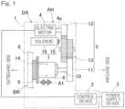
- the electric linear motion actuator DA includes an actuator body AH, and a control device 2, which is described later.
- the actuator body AH includes an electric motor 4, a speed reducing mechanism 5, a linear motion mechanism 6 serving as a friction member actuator, a parking brake mechanism 7, an angle sensor Sa, and a load sensor Sb.
- the electric motor 4, the speed reducing mechanism 5, and the linear motion mechanism 6 are incorporated into, for example, a housing which is not shown.
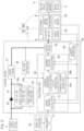
- Each control device 2 includes a step-up unit 19, a current flow direction restriction unit 20, a power storage unit 21, a voltage estimation unit 22, a processing unit 23, a motor driver 24, a current estimation unit 25, and an angular speed estimation unit 26.
- the step-up unit 19 steps up the voltage of the power supply device 3 to provide the stepped-up voltage (raised voltage) to the power storage unit 21, that is, stores charges in the power storage unit 21.
- the step-up unit 19 may be, for example, a CVCC (constant voltage and constant current) boost converter composed of a capacitor, an inductor, a switching element, a switch control circuit, and so on.
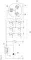
- Fig. 4A is a diagram schematically showing flow of power in a case where a capacitor voltage V2 (a voltage of the capacitor) is higher than a battery voltage V1 (a voltage of the battery), that is, (V 1 ⁇ V2) is satisfied, in Fig. 3 .
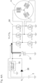
- Fig. 4A indicates a schematic diagram of flow of power in a case of V 1 ⁇ V2, specifically, in a case where the electric motor 4 performs a high-output operation (rapid braking manipulation) under a state where the electric motor 4 is continuously in a non-operating state or in an operation with low output and the capacitor has a high voltage because of the step-up circuit.
Landscapes
- Engineering & Computer Science (AREA)
- Power Engineering (AREA)
- Mechanical Engineering (AREA)
- General Engineering & Computer Science (AREA)
- Transportation (AREA)
- Braking Systems And Boosters (AREA)
- Regulating Braking Force (AREA)
- Braking Arrangements (AREA)
Claims (4)
- Elektrischer linearer Bewegungsaktuator, umfassend:einen Elektromotor (4);einen linearen Bewegungsmechanismus (6), der dazu konfiguriert ist, die Drehbewegung des Elektromotors (4) über eine Dreheingangs/-ausgangswelle in eine lineare Bewegung einer linearen Bewegungseinheit umzuwandeln; undeine Steuervorrichtung (2), die mit einer Energieversorgung (3) für Gleichstrom verbunden ist, wobei die Steuervorrichtung (2) zum Antreiben des Elektromotors (4) konfiguriert ist,wobei die Steuervorrichtung (2) Folgendes einschließteinen Motortreiber (24), der dazu konfiguriert ist, die einer Spule (4b) des Elektromotors (4) zuzuführende Energie zu steuern,eine Energiespeichereinheit (21), die mit dem Motortreiber (24) verbunden ist, wobei die Energiespeichereinheit (21) die von der Energieversorgung (3) gelieferte Energie speichert und dem Motortreiber (24) Energie zuführt,eine Stromflussrichtungsbegrenzungseinheit (20), die dazu konfiguriert ist, zu bewirken, dass der Strom nur in einer Richtung fließt, in der die Energie von der Energieversorgungsvorrichtung (3) geliefert wird, undeine Erhöhungseinheit (19), die dazu konfiguriert ist, die Spannung von der Energieversorgungsvorrichtung (3) zu erhöhen und die erhöhte Spannung an die Energiespeichereinheit (21) zu liefern,dadurch gekennzeichnet, dass die Stromflussrichtungsbegrenzungseinheit (20) mit der Energieversorgungsvorrichtung (3) und der Energiespeichereinheit (21) so verbunden ist, dass sie parallel zu der Erhöhungseinheit (19) ist,wobei in einem Fall, in dem Ladungen der Energiespeichereinheit (21) freigegeben wurden, Energie von der Energieversorgungsvorrichtung (3) über die Stromflussrichtungsbegrenzungseinheit (20) an den Motortreiber (24) geliefert wird; unddie Erhöhungseinheit (19) Folgendes einschließt:einen konstanten Strombegrenzungsabschnitt (19a), der dazu konfiguriert ist, wenn der von der Erhöhungseinheit (19) auszugebende Ausgangsstrom größer als ein eingestellter Wert ist, den Ausgabestrom auf den eingestellten Wert oder kleiner zu begrenzen; undeinen konstanten Spannungsbegrenzungsabschnitt (19b), der dazu konfiguriert ist, zu bewirken, dass die Erhöhungseinheit (19) eine vorbestimmte Spannung ausgibt, wenn der von der Erhöhungseinheit (19) auszugebende Ausgabestrom kleiner als oder gleich dem eingestellten Wert ist, und wobei eine durch den konstanten Strombegrenzungsabschnitt oder den konstanten Spannungsbegrenzungsabschnitt begrenzte Ausgabeenergie der Erhöhungseinheit (19) kleiner als die maximale Energie ist, wobei die maximale Energie die größte Verbrauchsleistung des Elektromotors (4) ist.
- Elektrischer linearer Bewegungsaktuator nach Anspruch 1, wobei die Energiespeichereinheit (21) ein Kondensator ist.
- Elektrisches Bremsgerät, umfassend:den elektrischen linearen Bewegungsaktuator nach Anspruch 1 oder 2;einen Bremsrotor (8), der mit einem Rad verbunden ist und sich mit diesem dreht; undein Reibungselement (9), das dazu konfiguriert ist, mit dem Bremsrotor (8) in Kontakt gebracht zu werden, um eine Bremskraft zu erzeugen, wobeider lineare Bewegungsmechanismus (6) einen Reibungselementaktuator einschließt, wobei der Reibungselementaktuator dazu konfiguriert ist, die Leistung des Elektromotors in eine Druckkraft des Reibungselements (9) umzuwandeln, unddie Steuervorrichtung (2) dazu konfiguriert ist, den Elektromotor (4) anzutreiben, um die Bremskraft zu steuern, wobei die Bremskraft erzeugt wird, wenn das Reibungselement (9) in Kontakt mit dem Bremsrotor (8) gebracht wird.
- Elektrisches Bremsgerät nach Anspruch 3, wobei das elektrische Bremsgerät ferner eine Fahrzeuggeschwindigkeitsschätzvorrichtung (30) umfasst, die dazu konfiguriert ist, eine Geschwindigkeit eines Fahrzeugs zu schätzen, an dem das elektrische Bremsgerät (1) montiert ist, wobei
in einem Fall, in dem die von der Fahrzeuggeschwindigkeitsschätzvorrichtung (30) geschätzte Geschwindigkeit innerhalb eines vorbestimmten Bereichs liegt, die Steuereinheit (2) dazu konfiguriert ist, die Ausgabespannung der Erhöhungseinheit (19) auf einen größeren Wert einzustellen, wenn die geschätzte Geschwindigkeit höher ist.
Applications Claiming Priority (2)
| Application Number | Priority Date | Filing Date | Title |
|---|---|---|---|
| JP2017011873A JP2018121461A (ja) | 2017-01-26 | 2017-01-26 | 電動式直動アクチュエータおよび電動ブレーキ装置 |
| PCT/JP2018/001709 WO2018139387A1 (ja) | 2017-01-26 | 2018-01-22 | 電動式直動アクチュエータおよび電動ブレーキ装置 |
Publications (3)
| Publication Number | Publication Date |
|---|---|
| EP3576294A1 EP3576294A1 (de) | 2019-12-04 |
| EP3576294A4 EP3576294A4 (de) | 2020-10-14 |
| EP3576294B1 true EP3576294B1 (de) | 2024-07-10 |
Family
ID=62979078
Family Applications (1)
| Application Number | Title | Priority Date | Filing Date |
|---|---|---|---|
| EP18744948.3A Active EP3576294B1 (de) | 2017-01-26 | 2018-01-22 | Elektrisches lineares stellglied und elektrische bremsvorrichtung |
Country Status (5)
| Country | Link |
|---|---|
| US (1) | US11441626B2 (de) |
| EP (1) | EP3576294B1 (de) |
| JP (1) | JP2018121461A (de) |
| CN (1) | CN110249522B (de) |
| WO (1) | WO2018139387A1 (de) |
Families Citing this family (4)
| Publication number | Priority date | Publication date | Assignee | Title |
|---|---|---|---|---|
| JP6873643B2 (ja) * | 2016-09-28 | 2021-05-19 | Ntn株式会社 | 電動ブレーキ装置 |
| KR102520639B1 (ko) | 2018-05-02 | 2023-04-11 | 삼성디스플레이 주식회사 | 입력 감지 장치 및 이를 포함하는 표시 장치 |
| JP7308070B2 (ja) * | 2019-04-26 | 2023-07-13 | ナブテスコ株式会社 | ブレーキ装置およびブレーキ制御システム |
| US20240400158A1 (en) * | 2023-06-05 | 2024-12-05 | Shimano Inc. | Electric device of human-powered vehicle |
Family Cites Families (16)
| Publication number | Priority date | Publication date | Assignee | Title |
|---|---|---|---|---|
| JP3153655B2 (ja) * | 1992-11-30 | 2001-04-09 | 三菱電機株式会社 | 電気車制御装置 |
| JP3166401B2 (ja) | 1993-05-17 | 2001-05-14 | 日産自動車株式会社 | 電動ブレーキ用アクチュエータ |
| JP4562849B2 (ja) * | 2000-03-30 | 2010-10-13 | 日立オートモティブシステムズ株式会社 | 電動ブレーキ装置 |
| JP3842654B2 (ja) * | 2002-01-17 | 2006-11-08 | 株式会社日立製作所 | 制動制御装置 |
| JP2005261180A (ja) * | 2004-02-09 | 2005-09-22 | Nsk Ltd | 車載用電動機の制御装置 |
| JP2006094594A (ja) * | 2004-09-22 | 2006-04-06 | Nsk Ltd | 車載用モータ制御装置、これを使用した電動パワーステアリング装置及び電動ブレーキ装置 |
| JP4898123B2 (ja) | 2005-01-13 | 2012-03-14 | Ntn株式会社 | 電動式直動アクチュエータおよび電動式ブレーキ装置 |
| JP2006219082A (ja) * | 2005-02-14 | 2006-08-24 | Hitachi Ltd | 車両用回転電機システム |
| JP4692244B2 (ja) * | 2005-11-25 | 2011-06-01 | トヨタ自動車株式会社 | 電力供給装置 |
| JP2009131110A (ja) | 2007-11-27 | 2009-06-11 | Toyota Industries Corp | 電源装置 |
| JP5165394B2 (ja) * | 2008-01-11 | 2013-03-21 | 日立オートモティブシステムズ株式会社 | 車両用電源システム |
| JP5645565B2 (ja) * | 2010-09-15 | 2014-12-24 | 三菱電機株式会社 | 電力変換装置および太陽光発電システム |
| JP6115119B2 (ja) * | 2012-12-21 | 2017-04-19 | 株式会社ジェイテクト | 電動パワーステアリング装置 |
| US9225284B2 (en) * | 2013-08-09 | 2015-12-29 | Woodward, Inc. | Controlling an electrically-driven actuator |
| JP6282424B2 (ja) * | 2013-09-04 | 2018-02-21 | Ntn株式会社 | 電動ブレーキ装置 |
| JP6736399B2 (ja) * | 2016-07-20 | 2020-08-05 | Ntn株式会社 | 電動ブレーキ装置および電動ブレーキシステム |
-
2017
- 2017-01-26 JP JP2017011873A patent/JP2018121461A/ja active Pending
-
2018
- 2018-01-22 WO PCT/JP2018/001709 patent/WO2018139387A1/ja not_active Ceased
- 2018-01-22 CN CN201880008289.8A patent/CN110249522B/zh active Active
- 2018-01-22 EP EP18744948.3A patent/EP3576294B1/de active Active
-
2019
- 2019-07-19 US US16/517,065 patent/US11441626B2/en active Active
Also Published As
| Publication number | Publication date |
|---|---|
| EP3576294A1 (de) | 2019-12-04 |
| EP3576294A4 (de) | 2020-10-14 |
| JP2018121461A (ja) | 2018-08-02 |
| US20190338817A1 (en) | 2019-11-07 |
| US11441626B2 (en) | 2022-09-13 |
| WO2018139387A1 (ja) | 2018-08-02 |
| CN110249522A (zh) | 2019-09-17 |
| CN110249522B (zh) | 2023-05-12 |
Similar Documents
| Publication | Publication Date | Title |
|---|---|---|
| US11441626B2 (en) | Electric linear actuator and electric brake device | |
| CN101472779B (zh) | 电动转向设备和用于控制电动转向设备的方法 | |
| US10654455B2 (en) | Electric brake device | |
| EP3170711B1 (de) | Elektrische bremsvorrichtung | |
| WO2016178428A1 (ja) | 電動ブレーキシステム | |
| EP3045359B1 (de) | Elektrische bremsvorrichtung | |
| US10479341B2 (en) | Electrically powered brake device | |
| JP2014168332A (ja) | モータ装置およびモータ駆動装置 | |
| EP3521115B1 (de) | Elektrische bremsvorrichtung | |
| WO2015190380A1 (ja) | 電動ブレーキ装置および電動ブレーキ装置システム | |
| EP3339121B1 (de) | Elektrische bremsvorrichtung | |
| US11001166B2 (en) | Electric brake apparatus and electric brake system | |
| WO2017026472A1 (ja) | 電動ブレーキシステム | |
| CN120641311A (zh) | 用于操控车辆的转向系统的电动马达的方法以及线控转向器 | |
| JP7089868B2 (ja) | 電動モータ装置および電動ブレーキ装置 | |
| US11001246B2 (en) | Electric brake device | |
| JP7066408B2 (ja) | 電動式直動アクチュエータおよび電動ブレーキ装置 | |
| JP2020043665A (ja) | 電動式アクチュエータおよび電動ブレーキ装置 | |
| WO2019049971A1 (ja) | 電動式アクチュエータおよび電動モータ装置 | |
| JP7347003B2 (ja) | モータ駆動装置 | |
| JP2019041503A (ja) | 電動式直動アクチュエータおよび電動ブレーキ装置 |
Legal Events
| Date | Code | Title | Description |
|---|---|---|---|
| STAA | Information on the status of an ep patent application or granted ep patent |
Free format text: STATUS: THE INTERNATIONAL PUBLICATION HAS BEEN MADE |
|
| PUAI | Public reference made under article 153(3) epc to a published international application that has entered the european phase |
Free format text: ORIGINAL CODE: 0009012 |
|
| STAA | Information on the status of an ep patent application or granted ep patent |
Free format text: STATUS: REQUEST FOR EXAMINATION WAS MADE |
|
| 17P | Request for examination filed |
Effective date: 20190725 |
|
| AK | Designated contracting states |
Kind code of ref document: A1 Designated state(s): AL AT BE BG CH CY CZ DE DK EE ES FI FR GB GR HR HU IE IS IT LI LT LU LV MC MK MT NL NO PL PT RO RS SE SI SK SM TR |
|
| AX | Request for extension of the european patent |
Extension state: BA ME |
|
| DAV | Request for validation of the european patent (deleted) | ||
| DAX | Request for extension of the european patent (deleted) | ||
| A4 | Supplementary search report drawn up and despatched |
Effective date: 20200911 |
|
| RIC1 | Information provided on ipc code assigned before grant |
Ipc: H02P 15/00 20060101AFI20200907BHEP Ipc: F16D 121/24 20120101ALN20200907BHEP Ipc: B60T 8/32 20060101ALI20200907BHEP Ipc: F16D 66/00 20060101ALN20200907BHEP Ipc: H02P 27/04 20160101ALI20200907BHEP Ipc: B60T 13/74 20060101ALI20200907BHEP |
|
| STAA | Information on the status of an ep patent application or granted ep patent |
Free format text: STATUS: EXAMINATION IS IN PROGRESS |
|
| 17Q | First examination report despatched |
Effective date: 20220204 |
|
| REG | Reference to a national code |
Ref country code: DE Ref legal event code: R079 Free format text: PREVIOUS MAIN CLASS: H02P0027040000 Ipc: H02P0015000000 Ref country code: DE Ref legal event code: R079 Ref document number: 602018071571 Country of ref document: DE Free format text: PREVIOUS MAIN CLASS: H02P0027040000 Ipc: H02P0015000000 |
|
| GRAP | Despatch of communication of intention to grant a patent |
Free format text: ORIGINAL CODE: EPIDOSNIGR1 |
|
| STAA | Information on the status of an ep patent application or granted ep patent |
Free format text: STATUS: GRANT OF PATENT IS INTENDED |
|
| RIC1 | Information provided on ipc code assigned before grant |
Ipc: F16D 121/24 20120101ALN20240116BHEP Ipc: F16D 66/00 20060101ALN20240116BHEP Ipc: B60T 13/74 20060101ALI20240116BHEP Ipc: B60T 8/32 20060101ALI20240116BHEP Ipc: H02P 27/04 20160101ALI20240116BHEP Ipc: H02P 15/00 20060101AFI20240116BHEP |
|
| INTG | Intention to grant announced |
Effective date: 20240207 |
|
| GRAS | Grant fee paid |
Free format text: ORIGINAL CODE: EPIDOSNIGR3 |
|
| GRAA | (expected) grant |
Free format text: ORIGINAL CODE: 0009210 |
|
| STAA | Information on the status of an ep patent application or granted ep patent |
Free format text: STATUS: THE PATENT HAS BEEN GRANTED |
|
| AK | Designated contracting states |
Kind code of ref document: B1 Designated state(s): AL AT BE BG CH CY CZ DE DK EE ES FI FR GB GR HR HU IE IS IT LI LT LU LV MC MK MT NL NO PL PT RO RS SE SI SK SM TR |
|
| REG | Reference to a national code |
Ref country code: CH Ref legal event code: EP |
|
| REG | Reference to a national code |
Ref country code: DE Ref legal event code: R096 Ref document number: 602018071571 Country of ref document: DE |
|
| REG | Reference to a national code |
Ref country code: LT Ref legal event code: MG9D |
|
| REG | Reference to a national code |
Ref country code: NL Ref legal event code: MP Effective date: 20240710 |
|
| PG25 | Lapsed in a contracting state [announced via postgrant information from national office to epo] |
Ref country code: PT Free format text: LAPSE BECAUSE OF FAILURE TO SUBMIT A TRANSLATION OF THE DESCRIPTION OR TO PAY THE FEE WITHIN THE PRESCRIBED TIME-LIMIT Effective date: 20241111 |
|
| REG | Reference to a national code |
Ref country code: AT Ref legal event code: MK05 Ref document number: 1702927 Country of ref document: AT Kind code of ref document: T Effective date: 20240710 |
|
| PG25 | Lapsed in a contracting state [announced via postgrant information from national office to epo] |
Ref country code: NL Free format text: LAPSE BECAUSE OF FAILURE TO SUBMIT A TRANSLATION OF THE DESCRIPTION OR TO PAY THE FEE WITHIN THE PRESCRIBED TIME-LIMIT Effective date: 20240710 |
|
| PG25 | Lapsed in a contracting state [announced via postgrant information from national office to epo] |
Ref country code: PT Free format text: LAPSE BECAUSE OF FAILURE TO SUBMIT A TRANSLATION OF THE DESCRIPTION OR TO PAY THE FEE WITHIN THE PRESCRIBED TIME-LIMIT Effective date: 20241111 Ref country code: NL Free format text: LAPSE BECAUSE OF FAILURE TO SUBMIT A TRANSLATION OF THE DESCRIPTION OR TO PAY THE FEE WITHIN THE PRESCRIBED TIME-LIMIT Effective date: 20240710 |
|
| PG25 | Lapsed in a contracting state [announced via postgrant information from national office to epo] |
Ref country code: NO Free format text: LAPSE BECAUSE OF FAILURE TO SUBMIT A TRANSLATION OF THE DESCRIPTION OR TO PAY THE FEE WITHIN THE PRESCRIBED TIME-LIMIT Effective date: 20241010 |
|
| PG25 | Lapsed in a contracting state [announced via postgrant information from national office to epo] |
Ref country code: GR Free format text: LAPSE BECAUSE OF FAILURE TO SUBMIT A TRANSLATION OF THE DESCRIPTION OR TO PAY THE FEE WITHIN THE PRESCRIBED TIME-LIMIT Effective date: 20241011 Ref country code: FI Free format text: LAPSE BECAUSE OF FAILURE TO SUBMIT A TRANSLATION OF THE DESCRIPTION OR TO PAY THE FEE WITHIN THE PRESCRIBED TIME-LIMIT Effective date: 20240710 Ref country code: PL Free format text: LAPSE BECAUSE OF FAILURE TO SUBMIT A TRANSLATION OF THE DESCRIPTION OR TO PAY THE FEE WITHIN THE PRESCRIBED TIME-LIMIT Effective date: 20240710 |
|
| PG25 | Lapsed in a contracting state [announced via postgrant information from national office to epo] |
Ref country code: BG Free format text: LAPSE BECAUSE OF FAILURE TO SUBMIT A TRANSLATION OF THE DESCRIPTION OR TO PAY THE FEE WITHIN THE PRESCRIBED TIME-LIMIT Effective date: 20240710 |
|
| PG25 | Lapsed in a contracting state [announced via postgrant information from national office to epo] |
Ref country code: LV Free format text: LAPSE BECAUSE OF FAILURE TO SUBMIT A TRANSLATION OF THE DESCRIPTION OR TO PAY THE FEE WITHIN THE PRESCRIBED TIME-LIMIT Effective date: 20240710 |
|
| PG25 | Lapsed in a contracting state [announced via postgrant information from national office to epo] |
Ref country code: IS Free format text: LAPSE BECAUSE OF FAILURE TO SUBMIT A TRANSLATION OF THE DESCRIPTION OR TO PAY THE FEE WITHIN THE PRESCRIBED TIME-LIMIT Effective date: 20241110 Ref country code: AT Free format text: LAPSE BECAUSE OF FAILURE TO SUBMIT A TRANSLATION OF THE DESCRIPTION OR TO PAY THE FEE WITHIN THE PRESCRIBED TIME-LIMIT Effective date: 20240710 |
|
| PG25 | Lapsed in a contracting state [announced via postgrant information from national office to epo] |
Ref country code: HR Free format text: LAPSE BECAUSE OF FAILURE TO SUBMIT A TRANSLATION OF THE DESCRIPTION OR TO PAY THE FEE WITHIN THE PRESCRIBED TIME-LIMIT Effective date: 20240710 |
|
| PG25 | Lapsed in a contracting state [announced via postgrant information from national office to epo] |
Ref country code: ES Free format text: LAPSE BECAUSE OF FAILURE TO SUBMIT A TRANSLATION OF THE DESCRIPTION OR TO PAY THE FEE WITHIN THE PRESCRIBED TIME-LIMIT Effective date: 20240710 Ref country code: RS Free format text: LAPSE BECAUSE OF FAILURE TO SUBMIT A TRANSLATION OF THE DESCRIPTION OR TO PAY THE FEE WITHIN THE PRESCRIBED TIME-LIMIT Effective date: 20241010 |
|
| PG25 | Lapsed in a contracting state [announced via postgrant information from national office to epo] |
Ref country code: RS Free format text: LAPSE BECAUSE OF FAILURE TO SUBMIT A TRANSLATION OF THE DESCRIPTION OR TO PAY THE FEE WITHIN THE PRESCRIBED TIME-LIMIT Effective date: 20241010 Ref country code: PL Free format text: LAPSE BECAUSE OF FAILURE TO SUBMIT A TRANSLATION OF THE DESCRIPTION OR TO PAY THE FEE WITHIN THE PRESCRIBED TIME-LIMIT Effective date: 20240710 Ref country code: NO Free format text: LAPSE BECAUSE OF FAILURE TO SUBMIT A TRANSLATION OF THE DESCRIPTION OR TO PAY THE FEE WITHIN THE PRESCRIBED TIME-LIMIT Effective date: 20241010 Ref country code: LV Free format text: LAPSE BECAUSE OF FAILURE TO SUBMIT A TRANSLATION OF THE DESCRIPTION OR TO PAY THE FEE WITHIN THE PRESCRIBED TIME-LIMIT Effective date: 20240710 Ref country code: IS Free format text: LAPSE BECAUSE OF FAILURE TO SUBMIT A TRANSLATION OF THE DESCRIPTION OR TO PAY THE FEE WITHIN THE PRESCRIBED TIME-LIMIT Effective date: 20241110 Ref country code: HR Free format text: LAPSE BECAUSE OF FAILURE TO SUBMIT A TRANSLATION OF THE DESCRIPTION OR TO PAY THE FEE WITHIN THE PRESCRIBED TIME-LIMIT Effective date: 20240710 Ref country code: GR Free format text: LAPSE BECAUSE OF FAILURE TO SUBMIT A TRANSLATION OF THE DESCRIPTION OR TO PAY THE FEE WITHIN THE PRESCRIBED TIME-LIMIT Effective date: 20241011 Ref country code: FI Free format text: LAPSE BECAUSE OF FAILURE TO SUBMIT A TRANSLATION OF THE DESCRIPTION OR TO PAY THE FEE WITHIN THE PRESCRIBED TIME-LIMIT Effective date: 20240710 Ref country code: ES Free format text: LAPSE BECAUSE OF FAILURE TO SUBMIT A TRANSLATION OF THE DESCRIPTION OR TO PAY THE FEE WITHIN THE PRESCRIBED TIME-LIMIT Effective date: 20240710 Ref country code: BG Free format text: LAPSE BECAUSE OF FAILURE TO SUBMIT A TRANSLATION OF THE DESCRIPTION OR TO PAY THE FEE WITHIN THE PRESCRIBED TIME-LIMIT Effective date: 20240710 Ref country code: AT Free format text: LAPSE BECAUSE OF FAILURE TO SUBMIT A TRANSLATION OF THE DESCRIPTION OR TO PAY THE FEE WITHIN THE PRESCRIBED TIME-LIMIT Effective date: 20240710 |
|
| REG | Reference to a national code |
Ref country code: DE Ref legal event code: R097 Ref document number: 602018071571 Country of ref document: DE |
|
| PG25 | Lapsed in a contracting state [announced via postgrant information from national office to epo] |
Ref country code: RO Free format text: LAPSE BECAUSE OF FAILURE TO SUBMIT A TRANSLATION OF THE DESCRIPTION OR TO PAY THE FEE WITHIN THE PRESCRIBED TIME-LIMIT Effective date: 20240710 Ref country code: SM Free format text: LAPSE BECAUSE OF FAILURE TO SUBMIT A TRANSLATION OF THE DESCRIPTION OR TO PAY THE FEE WITHIN THE PRESCRIBED TIME-LIMIT Effective date: 20240710 Ref country code: DK Free format text: LAPSE BECAUSE OF FAILURE TO SUBMIT A TRANSLATION OF THE DESCRIPTION OR TO PAY THE FEE WITHIN THE PRESCRIBED TIME-LIMIT Effective date: 20240710 |
|
| PG25 | Lapsed in a contracting state [announced via postgrant information from national office to epo] |
Ref country code: EE Free format text: LAPSE BECAUSE OF FAILURE TO SUBMIT A TRANSLATION OF THE DESCRIPTION OR TO PAY THE FEE WITHIN THE PRESCRIBED TIME-LIMIT Effective date: 20240710 |
|
| PG25 | Lapsed in a contracting state [announced via postgrant information from national office to epo] |
Ref country code: CZ Free format text: LAPSE BECAUSE OF FAILURE TO SUBMIT A TRANSLATION OF THE DESCRIPTION OR TO PAY THE FEE WITHIN THE PRESCRIBED TIME-LIMIT Effective date: 20240710 |
|
| PG25 | Lapsed in a contracting state [announced via postgrant information from national office to epo] |
Ref country code: IT Free format text: LAPSE BECAUSE OF FAILURE TO SUBMIT A TRANSLATION OF THE DESCRIPTION OR TO PAY THE FEE WITHIN THE PRESCRIBED TIME-LIMIT Effective date: 20240710 Ref country code: SK Free format text: LAPSE BECAUSE OF FAILURE TO SUBMIT A TRANSLATION OF THE DESCRIPTION OR TO PAY THE FEE WITHIN THE PRESCRIBED TIME-LIMIT Effective date: 20240710 |
|
| PLBE | No opposition filed within time limit |
Free format text: ORIGINAL CODE: 0009261 |
|
| STAA | Information on the status of an ep patent application or granted ep patent |
Free format text: STATUS: NO OPPOSITION FILED WITHIN TIME LIMIT |
|
| 26N | No opposition filed |
Effective date: 20250411 |
|
| REG | Reference to a national code |
Ref country code: CH Ref legal event code: PL |
|
| PG25 | Lapsed in a contracting state [announced via postgrant information from national office to epo] |
Ref country code: SE Free format text: LAPSE BECAUSE OF FAILURE TO SUBMIT A TRANSLATION OF THE DESCRIPTION OR TO PAY THE FEE WITHIN THE PRESCRIBED TIME-LIMIT Effective date: 20240710 |
|
| PG25 | Lapsed in a contracting state [announced via postgrant information from national office to epo] |
Ref country code: MC Free format text: LAPSE BECAUSE OF FAILURE TO SUBMIT A TRANSLATION OF THE DESCRIPTION OR TO PAY THE FEE WITHIN THE PRESCRIBED TIME-LIMIT Effective date: 20240710 Ref country code: LU Free format text: LAPSE BECAUSE OF NON-PAYMENT OF DUE FEES Effective date: 20250122 |
|
| GBPC | Gb: european patent ceased through non-payment of renewal fee |
Effective date: 20250122 |
|
| PG25 | Lapsed in a contracting state [announced via postgrant information from national office to epo] |
Ref country code: GB Free format text: LAPSE BECAUSE OF NON-PAYMENT OF DUE FEES Effective date: 20250122 Ref country code: BE Free format text: LAPSE BECAUSE OF NON-PAYMENT OF DUE FEES Effective date: 20250131 |
|
| PG25 | Lapsed in a contracting state [announced via postgrant information from national office to epo] |
Ref country code: CH Free format text: LAPSE BECAUSE OF NON-PAYMENT OF DUE FEES Effective date: 20250131 |
|
| REG | Reference to a national code |
Ref country code: BE Ref legal event code: MM Effective date: 20250131 |
|
| PGFP | Annual fee paid to national office [announced via postgrant information from national office to epo] |
Ref country code: FR Payment date: 20251128 Year of fee payment: 9 |
|
| PG25 | Lapsed in a contracting state [announced via postgrant information from national office to epo] |
Ref country code: IE Free format text: LAPSE BECAUSE OF NON-PAYMENT OF DUE FEES Effective date: 20250122 |
|
| PGFP | Annual fee paid to national office [announced via postgrant information from national office to epo] |
Ref country code: DE Payment date: 20251203 Year of fee payment: 9 |