EP3575547A2 - Flüssigkeit zur verwendung in energieerzeugungsumgebungen - Google Patents
Flüssigkeit zur verwendung in energieerzeugungsumgebungen Download PDFInfo
- Publication number
- EP3575547A2 EP3575547A2 EP19170948.4A EP19170948A EP3575547A2 EP 3575547 A2 EP3575547 A2 EP 3575547A2 EP 19170948 A EP19170948 A EP 19170948A EP 3575547 A2 EP3575547 A2 EP 3575547A2
- Authority
- EP
- European Patent Office
- Prior art keywords
- fluid
- well
- pressure
- loop
- temperature
- Prior art date
- Legal status (The legal status is an assumption and is not a legal conclusion. Google has not performed a legal analysis and makes no representation as to the accuracy of the status listed.)
- Withdrawn
Links
Images


Classifications
-
- F—MECHANICAL ENGINEERING; LIGHTING; HEATING; WEAPONS; BLASTING
- F03—MACHINES OR ENGINES FOR LIQUIDS; WIND, SPRING, OR WEIGHT MOTORS; PRODUCING MECHANICAL POWER OR A REACTIVE PROPULSIVE THRUST, NOT OTHERWISE PROVIDED FOR
- F03G—SPRING, WEIGHT, INERTIA OR LIKE MOTORS; MECHANICAL-POWER PRODUCING DEVICES OR MECHANISMS, NOT OTHERWISE PROVIDED FOR OR USING ENERGY SOURCES NOT OTHERWISE PROVIDED FOR
- F03G7/00—Mechanical-power-producing mechanisms, not otherwise provided for or using energy sources not otherwise provided for
-
- E—FIXED CONSTRUCTIONS
- E21—EARTH OR ROCK DRILLING; MINING
- E21B—EARTH OR ROCK DRILLING; OBTAINING OIL, GAS, WATER, SOLUBLE OR MELTABLE MATERIALS OR A SLURRY OF MINERALS FROM WELLS
- E21B43/00—Methods or apparatus for obtaining oil, gas, water, soluble or meltable materials or a slurry of minerals from wells
- E21B43/30—Specific pattern of wells, e.g. optimising the spacing of wells
- E21B43/305—Specific pattern of wells, e.g. optimising the spacing of wells comprising at least one inclined or horizontal well
-
- F—MECHANICAL ENGINEERING; LIGHTING; HEATING; WEAPONS; BLASTING
- F24—HEATING; RANGES; VENTILATING
- F24T—GEOTHERMAL COLLECTORS; GEOTHERMAL SYSTEMS
- F24T50/00—Geothermal systems
-
- C—CHEMISTRY; METALLURGY
- C09—DYES; PAINTS; POLISHES; NATURAL RESINS; ADHESIVES; COMPOSITIONS NOT OTHERWISE PROVIDED FOR; APPLICATIONS OF MATERIALS NOT OTHERWISE PROVIDED FOR
- C09K—MATERIALS FOR MISCELLANEOUS APPLICATIONS, NOT PROVIDED FOR ELSEWHERE
- C09K8/00—Compositions for drilling of boreholes or wells; Compositions for treating boreholes or wells, e.g. for completion or for remedial operations
- C09K8/02—Well-drilling compositions
- C09K8/04—Aqueous well-drilling compositions
-
- E—FIXED CONSTRUCTIONS
- E21—EARTH OR ROCK DRILLING; MINING
- E21B—EARTH OR ROCK DRILLING; OBTAINING OIL, GAS, WATER, SOLUBLE OR MELTABLE MATERIALS OR A SLURRY OF MINERALS FROM WELLS
- E21B7/00—Special methods or apparatus for drilling
- E21B7/04—Directional drilling
-
- F—MECHANICAL ENGINEERING; LIGHTING; HEATING; WEAPONS; BLASTING
- F03—MACHINES OR ENGINES FOR LIQUIDS; WIND, SPRING, OR WEIGHT MOTORS; PRODUCING MECHANICAL POWER OR A REACTIVE PROPULSIVE THRUST, NOT OTHERWISE PROVIDED FOR
- F03G—SPRING, WEIGHT, INERTIA OR LIKE MOTORS; MECHANICAL-POWER PRODUCING DEVICES OR MECHANISMS, NOT OTHERWISE PROVIDED FOR OR USING ENERGY SOURCES NOT OTHERWISE PROVIDED FOR
- F03G4/00—Devices for producing mechanical power from geothermal energy
- F03G4/074—Safety arrangements
-
- F—MECHANICAL ENGINEERING; LIGHTING; HEATING; WEAPONS; BLASTING
- F03—MACHINES OR ENGINES FOR LIQUIDS; WIND, SPRING, OR WEIGHT MOTORS; PRODUCING MECHANICAL POWER OR A REACTIVE PROPULSIVE THRUST, NOT OTHERWISE PROVIDED FOR
- F03G—SPRING, WEIGHT, INERTIA OR LIKE MOTORS; MECHANICAL-POWER PRODUCING DEVICES OR MECHANISMS, NOT OTHERWISE PROVIDED FOR OR USING ENERGY SOURCES NOT OTHERWISE PROVIDED FOR
- F03G7/00—Mechanical-power-producing mechanisms, not otherwise provided for or using energy sources not otherwise provided for
- F03G7/04—Mechanical-power-producing mechanisms, not otherwise provided for or using energy sources not otherwise provided for using pressure differences or thermal differences occurring in nature
- F03G7/047—Environmental heat plants or OTEC plants using heat pumps
-
- F—MECHANICAL ENGINEERING; LIGHTING; HEATING; WEAPONS; BLASTING
- F24—HEATING; RANGES; VENTILATING
- F24T—GEOTHERMAL COLLECTORS; GEOTHERMAL SYSTEMS
- F24T10/00—Geothermal collectors
- F24T10/10—Geothermal collectors with circulation of working fluids through underground channels, the working fluids not coming into direct contact with the ground
- F24T10/13—Geothermal collectors with circulation of working fluids through underground channels, the working fluids not coming into direct contact with the ground using tube assemblies suitable for insertion into boreholes in the ground, e.g. geothermal probes
- F24T10/15—Geothermal collectors with circulation of working fluids through underground channels, the working fluids not coming into direct contact with the ground using tube assemblies suitable for insertion into boreholes in the ground, e.g. geothermal probes using bent tubes; using tubes assembled with connectors or with return headers
-
- F—MECHANICAL ENGINEERING; LIGHTING; HEATING; WEAPONS; BLASTING
- F24—HEATING; RANGES; VENTILATING
- F24T—GEOTHERMAL COLLECTORS; GEOTHERMAL SYSTEMS
- F24T10/00—Geothermal collectors
- F24T10/20—Geothermal collectors using underground water as working fluid; using working fluid injected directly into the ground, e.g. using injection wells and recovery wells
-
- F—MECHANICAL ENGINEERING; LIGHTING; HEATING; WEAPONS; BLASTING
- F24—HEATING; RANGES; VENTILATING
- F24T—GEOTHERMAL COLLECTORS; GEOTHERMAL SYSTEMS
- F24T10/00—Geothermal collectors
- F24T10/40—Geothermal collectors operated without external energy sources, e.g. using thermosiphonic circulation or heat pipes
-
- F—MECHANICAL ENGINEERING; LIGHTING; HEATING; WEAPONS; BLASTING
- F24—HEATING; RANGES; VENTILATING
- F24T—GEOTHERMAL COLLECTORS; GEOTHERMAL SYSTEMS
- F24T10/00—Geothermal collectors
- F24T2010/50—Component parts, details or accessories
- F24T2010/53—Methods for installation
-
- F—MECHANICAL ENGINEERING; LIGHTING; HEATING; WEAPONS; BLASTING
- F24—HEATING; RANGES; VENTILATING
- F24T—GEOTHERMAL COLLECTORS; GEOTHERMAL SYSTEMS
- F24T10/00—Geothermal collectors
- F24T2010/50—Component parts, details or accessories
- F24T2010/56—Control arrangements
-
- Y—GENERAL TAGGING OF NEW TECHNOLOGICAL DEVELOPMENTS; GENERAL TAGGING OF CROSS-SECTIONAL TECHNOLOGIES SPANNING OVER SEVERAL SECTIONS OF THE IPC; TECHNICAL SUBJECTS COVERED BY FORMER USPC CROSS-REFERENCE ART COLLECTIONS [XRACs] AND DIGESTS
- Y02—TECHNOLOGIES OR APPLICATIONS FOR MITIGATION OR ADAPTATION AGAINST CLIMATE CHANGE
- Y02E—REDUCTION OF GREENHOUSE GAS [GHG] EMISSIONS, RELATED TO ENERGY GENERATION, TRANSMISSION OR DISTRIBUTION
- Y02E10/00—Energy generation through renewable energy sources
- Y02E10/10—Geothermal energy
Definitions
- the present invention relates to fluids for power production in a variety of geothermal and well environments and more particularly, the present invention relates to the use of classes of fluids used in methods for generating power.
- geothermal energy is well known and have been the subject matter of many publications and patents.
- the general concept is to drill into a formation to extract heat therefrom and return the generated steam and water to the surface where the steam drives, for example, a power generating device.
- Traditional industrial geothermal technology requires rare geological conditions causing the technology to remain niche on a global scale.
- the geothermal gradient is generally defined as the rate of temperature increase relative to increasing depth in the interior of the Earth. Quantitatively, this represents approximately 25°C for each kilometre. As such, this amount of energy is too substantive to leave unused.
- WellStar Energy in a press release dated December 1, 2016 briefly touches on the possibility of incorporating unused wells with a geothermal loop for energy recovery, however no specific details are mentioned in this regard or for interconnection of wells for thermal management.
- Chevron in an undated video disclosure, taught gas well interconnection at the Congo River Canyon Crossing Pipeline Project. An interconnecting pipeline was run from one side of the river to the other for supplying gas. Again, this was a specific use for well interconnection. Well recycle and interconnection in a geothermal loop was not discussed.
- GreenFire Energy in an article dated 2017, discuss a looped geothermal energy recovery system. Rather than using preexisting gas/oil wells for repurposing, new wells are drilled. This does nothing to control improperly maintained unused wells and in fact may contribute to new problems. The disclosure is silent on techniques used to effect the loop and further does not contemplate clustering and consolidation necessary for maximum efficiency. Furthermore, contemplated working fluids consist of CO2 and other refrigerants, none of which exhibit a substantially non-linear temperature-enthalpy relationship at pressures and temperatures of relevance for energy production from the geothermal gradient.
- the present invention overcomes these difficulties and has for one of its objects the provision of an improved geothermal power generation system in which the water obtaining heat from the hot rock strata does not become contaminated so that it can be recycled, does not require chemical treatment beyond that used in standard boiler water treatment, and is economical in the amount of water used.
- Another object of the present invention is the provision of an improved geothermal power generation system in which the turbine turning a generator or other mechanism that is to be powered by the steam needed not be located near the input well that is used to receive water into the ground and can be at a location remote from that well.
- Another object of the present invention is the provision of an improved geothermal power generation system in which the system is more efficient.
- Another object of the present invention is the provision of an improved geothermal power generation system in which the system is easy to install because the wells can be drilled by horizontal well drilling techniques in common use in the oil industry.
- the improved geothermal power generation system is simple to use.
- Another object of the present invention is that the system is maintained without withdrawing water from the strata so that the pressure in the strata is maintained.”
- Halff generally discusses multiple legs in the system, however no details are provided in this complex area. It is indicated in the text that: "A variation of the system described above is shown Figure. All of the elements of the System shown in FIG. 1 are present. The same results are accomplished with a single vertical well and one or more horizontal wells. The water is returned to the horizontal reach of the well with a tubing that extends down the casing and discharges at the end of the casing. The water is converted to steam as it flows back out the single well and hence to the turbine.
- the treated water may be at either end of the hot water leg or distributed along all or part of the hot water leg.
- hot legs there be one or more hot legs.
- the hot legs may all operate at the same time or they may be used in sequence with one hot leg in operation while the other legs are heating up until the other legs are ready and are sequentially put into service.”
- the author teaches a zeotropic mixture as a working fluid heated to a supercritical state by exchanging heat from a sensible heat source.
- the teachings combine a supercritical Rankine cycle and a zeotropic mixture.
- the working fluid is heated directly from a liquid to a supercritical state, which improves the thermal matching between the sensible heat source and the working fluid.
- Using a zeotropic mixture as the working fluid creates a better thermal match between the working fluid and the cooling agent.
- the present invention takes the opposite approach wherein the temperature difference between the heat source and fluid is maximized rather than matched.
- GreenFire Energy Inc. in WO 2015/134974, published September 11, 2015 , teach a process and method for producing geothermal power.
- the authors teach a closed-loop geothermal system where: "The heat transfer fluid circulating through the system may include one or more of carbon dioxide, nitrogen, ammonia and/or amines with carbon number Ci through C6, hydrocarbons with carbon number Ci through C8, hydrocarbons with carbon number Ci through Cio with one or more hydrogens being replaced by chlorine or fluorine.
- the circulating fluid is supercritical carbon dioxide. Teachings regarding increased efficiency by fundamentally increasing heat transfer from the rock are absent. Furthermore, all the fluids contemplated do not exhibit a nonlinear temperature-enthalpy relationship at pressures and temperatures relevant for energy production from the geothermal gradient, greater than 10 MPa and less than 180°C respectively.
- the present invention provides fluid classes in novel applications to produce power with an integrated cycle and segregated cycle by a clear understanding of the thermodynamics involved in a variety of geothermal and well environments.
- a global object of the present invention is to provide fluid classes for heat and power production in a variety of well and geothermal environments for maximum energy recovery.
- Another object of one embodiment of the present invention is to provide a fluid for energy recovery use in a well system having an inlet well, an outlet well and lateral interconnection between, the fluid having at least one property selected from the group, comprising:
- Classes of compounds subscribing to the above noted properties increase the temperature difference between the far-field rock temperature and the circulating fluid temperature, thus driving higher heat transfer from the geologic formation.
- the fluid may comprise an aqueous solution of magnesium sulphate.
- a still further object of one embodiment of the present invention is to provide a method of generating power, comprising:
- Yet another object of one embodiment of the present invention is to provide a method of repurposing an oilfield having pre-existing production wells and injection wells in spaced relation in a formation to capture heat energy, comprising:
- the fluid can be selected based on the configuration of the wells, heat source quality inter alia to maximize efficiency.
- a still further object of one embodiment of the present invention is to provide a geothermal method, comprising:
- a suitable fluid may be selected from those embraced by the classes as noted previously.
- Another object of one embodiment of the present invention is to provide a geothermal method, comprising:
- a still further object of one embodiment of the present invention is to provide a method for recycling unused drilled wells, comprising:
- Yet another object of one embodiment of the present invention is to provide a method of generating power, the method comprising:
- thermodynamic properties of the fluid affords broad applicability in very beneficial power generation and direct heat use environments.
- FIG. 1 shown is a schematic illustration of first embodiment of the invention. This is referred to as a segregated well loop and power cycle.
- a power cycle 10 is integrated with a well loop cycle 12.
- the power cycle 10 may be selected from any of those suitable and known such as a Stirling cycle, carbon carrier cycle, Kalina cycle, organic Rankine cycle, carbon dioxide transcritical power cycle, inter alia.
- the well loop 12 comprises a closed loop system having an inlet well 14 and an outlet well 16, typically disposed within a geological formation, which may be, for example, a geothermal formation, low permeability formation, sedimentary formation, volcanic formation or "basement' formation which is more appropriately described as crystalline rock occurring beneath the sedimentary basin (none being shown).
- a geological formation which may be, for example, a geothermal formation, low permeability formation, sedimentary formation, volcanic formation or "basement' formation which is more appropriately described as crystalline rock occurring beneath the sedimentary basin (none being shown).
- the well loop 12 and power cycle 10 are in thermal contact by heat exchanger 16 which recovers heat from the working fluid circulating in the loop circuit 20 in the formation which is subsequently used to generate power with generator 22 in cycle 10.
- the temperature of the formation may be in the range of between 80°C and 250°C.
- the existing power cycles supra require a simple water-based fluid within the well loop itself which absorbs heat from the rock and then transfers this heat into the secondary power cycle working fluid in a heat exchanger.
- the water chemistry is set by the reservoir conditions.
- the water is a heavy brine with high total dissolved solids (TDS) content above 10,000 ppm that causes two problems, namely corrosion and scaling.
- TDS total dissolved solids
- Corrosion issues in the downhole pipes, tools, and within the surface facility and surface flow lines are common and expensive to manage.
- the working fluid in the well-loop cycle is formulated so that it does not freeze below 0 degrees Celsius, and in the present invention has at least one property selected from the group comprising:
- Figure 2 illustrates a segregated circuit incorporating a well loop 12 in thermal contact with two distinct heat exchangers 18 each with its own power generator 22 forming a parallel arrangement.
- Figure 3 illustrates a serial arrangement.
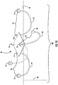
- FIG. 4 schematically illustrated is partially cut away view of a multilateral well loop system, globally denoted by numeral 24.
- a plurality of horizontal well loop segments 20 are disposed within the formation (not shown) in spaced apart generally parallel relation.
- Each of the segments 20 is commonly connected to an inlet well 14 and an outlet well 16 in a closed loop.
- the geological formation may be, for example, a geothermal formation, low permeability formation, sedimentary formation, volcanic formation or "basement' formation which is more appropriately described as crystalline rock occurring beneath the sedimentary basin (none being shown).
- Figure 5 schematically illustrates the disposition of the elements within a geological formation 26.
- the horizontal segments 20 may be anywhere from 2000 metres to 8000 metres or more in length and from 1000 metres to 6000 metres in depth from the surface 28.
- a power generation circuit 22 on surface 28 is disposed between the inlet well 14 and the outlet well 16 to complete the closed loop system.
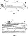
- the integrated well loop power cycle is a closed loop system in which the selected working fluid is circulated within the well loop and then flows into a turbine on surface as shown in Figure 6 .
- Numeral 30 denotes the overall process schematic. In this process, a single-fluid is used rather than having a discreet well loop fluid and a secondary power cycle working fluid.
- the working fluid in this closed loop cycle can operate either as a transcritical cycle, whereby the fluid is supercritical at the upper working pressure and subcritical at the lower working pressure, or as an entirely supercritical cycle whereby the fluid remains supercritical at the lower working pressure.
- a transcritical cycle is a thermodynamic cycle where the working fluid goes through both the subcritical and supercritical states.
- suitable fluids for use in the technology set forth herein are capable of transitioning from a supercritical state at the outlet well to a transcritical state after expanding and cooling, wherein the fluid exiting the outlet well has an entropy sufficiently high to expand to a superheated vapor state to the right of the two phase region on a Temperature-Entropy graph and upon cooling is substantially below its critical point.
- the driving mechanism in this integrated cycle is a very strong thermosiphon which arises due to the density difference between the inlet vertical well 14 and the outlet vertical well 16.
- the fluid is in a supercritical liquid state in the inlet well 14, heats up as it travels along the lateral sections 12 and exits in a supercritical state in the outlet well 16, which creates significant pressure.
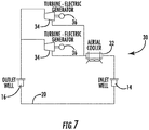
- Figure 7 is a variation of the flow diagram illustrated in Figure 6 , where a plurality of turbines 34 and generators 36 are disposed in a parallel relationship. Other variations including combinations of series and parallel will be appreciated by those skilled in the art.
- Figure 8 is an illustrative schematic of the fluid temperature within the lateral portion of a well loop, for simple fluids described in prior art, and the novel fluids described herein that demonstrate a non-linear temperature-enthalpy relationship.
- the heat transferred from the rock is proportional to the cumulative area between the rock temperature and the fluid temperature.
- Table 1 tabulates the data.
- thermosiphon effect can completely eliminate the need for a surface pump under normal operating conditions except during start-up.
- this eliminates the power required to operate the pump and increases the net electrical power output.
- an aqueous precipitate/electrolyte solution with temperature-dependent solubility wherein the water is super saturated at the top of the inlet well.
- the solid particles are held in suspension with an anti-scaling agent (anti-flocculation agent) and with turbulent flow (similar to a drilling mud).
- anti-scaling agent anti-flocculation agent
- turbulent flow similar to a drilling mud.
- temperature is increasing, hence the solubility of the solids held in suspension is also increasing. This allows the solution to endothermically absorb heat from the rock (basically increases the effective heat capacity of the fluid) as the solid particles dissolve into the water.
- temperature In the heat exchanger to the segregated heat-to-power cycle, temperature is decreasing, so the solid substance is precipitating exothermically.
- the heat exchanger may be treated to avoid precipitates adhering to the interior surfaces.
- Fluids for application in a closed-loop geothermal system include aqueous solutions with the following solutes as examples: potassium bromide, magnesium sulphate.
- control logic (not shown) automatically shifts the working fluid to the appropriate turbine to maintain high efficiency throughout the year.
- each surface location generally denoted by numeral 46, includes an injection well 48 connected to a lateral well conduit 50 and production well 52.
- the continuous well structure subscribes to a generally U shaped structure.
- each location 46 is discrete and linked to proximal locations in an elegant and advantageous manner.
- the distance between locations may be 5000 meters. This will, of course, vary from one situation to another.
- numeral 54 is representative of the power generation apparatus. Selections for the apparatus 54 will be discussed herein after, however for purposes of discussion, the apparatus 54 is responsible for converting steam into electrical energy.
- the apparatus 54 is responsible for converting steam into electrical energy.
- the multilateral conduits 38 are similarly subterranean, but also within a geothermal zone 46 of formation 48.
- Figure 10 may also be referenced.
- a fluid with a suitable heat capacity is circulated in the injection well 48 of one location 46, processed through power generation apparatus 54 to recover the heat energy and subsequently passed as an output stream to be an inlet feed stream for a injection well 48 of a proximal location 46.
- the chain line 62 illustrates this relay or daisy chain sequencing. Since not all of the heat is recovered, the inlet feed stream for well 48 of a proximal location is preheated for injection into lateral conduit 50. The process then resets for repetition in the next location 46.
- power generation apparatus includes a bypass loop 64 for bypassing the apparatus 54.
- an array of conduits 50 may be employed as illustrated in Figure 9A .
- the arrays will be referenced as multilateral arrays 66 and are arranged in an annular pattern in spaced relation from proximal conduits 50. Other patterns may be employed depending on the specifics of the situation. Connection between the individual conduits 50 of an array 66 will simply be integrated in a merger acting in a similar fashion to a single conduit 50. All or some of the locations 46 may be fabricated in this way, depending on the conditions of which examples have been referenced above. It is further contemplated that singular conduit arrangements may alternate with arrays 66.
- the arrays 66 increase the overall flow rate and power production. In situations where some locations 46 are closer together, a greater number of arrays 66 may be used to maintain heat recovery balance.
- the arrangement shown in Figure 9 is exemplary of a 12,000 kW to 20,000 kW system.
- FIG. 11 shown is a further embodiment of the invention for example, an 8,000kW to 12,000kW system.
- individual loops may be joined at a centralized location 68 in order to centralize the power generation apparatus (not shown) for increased power and efficiency.
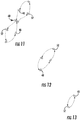
- Figures 12 and 13 illustrate smaller scale operations, 4,000kW- 6,000kW ( Figure 12 ) and 2,000kW - 3,000kW ( Figure 13 ).
- the daisy chaining since well loops are linked front to back, eliminates the need for a near surface return conduit. Further, the paired loops act as the return conduit for each other with the pair using waste heat as an input to create the preheated stream supra.
- FIG. 14 shown is a schematic illustration of a drilled area generally denoted by numeral 70 with a plurality of dispersed unused wells 72.
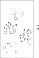
- FIG. 15 shown is a similar illustration to Figure 14 , however a plurality of new wells 74 through 88 have been drilled proximate a respective unused well 72 .
- a main hub 90 is provided. Although not specifically shown, hub 90 is effectively a manifold arrangement where each of the new wells, for example, 74, 76, 78 and 80 are in fluid communication discussed in greater detail herein after. From the hub 90, each of the new wells 74, 76 and 78 are spaced from each other and unused well 72 associated with the hub 90. Each new well 74, 76 and 78 is in fluid communication with a single proximate unused well 72. Fluid communication is achieved by piping 92 and 94. Piping 92 is disposed below the surface 96 and more specifically within a geothermal zone, generally denoted by numeral 98. As is illustrated, piping 92 is disposed above the surface 96 in the example, however it may be disposed below surface 96 which will be shown in the advancing Figures.
- hub 90 with the new wells 74, 76 and 78 in the example are connected to a respective unused well 72 to form clusters of recycled unused wells.
- Figures 16 and 17 can be referenced together and the loops 92 and 94 are absent in Figure 17 for purposes of clarity.
- a cluster can be referenced in Figure 16 denoted by numeral 100.
- the clustering is effective for linking additional clusters 100 as shown in Figure 17 .
- the new wells 74, 76 and 78 associated with a given hub 90 link other clusters 100 by way of an unused well 72 from an adjacent cluster 100. Such a link is referenced as 102 for purposes of explanation.
- the clusters 100 are consolidated as an energy collecting system as opposed to a random unproductive array of unused wells 72 shown in Figure 15 . This provides a high efficiency arrangement for collecting geothermal energy in a closed loop surface to surface design.
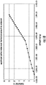
- FIG 18 shown is the nonlinear temperature-enthalpy relationship of an aqueous solution of 20 mass percent magnesium sulphate at 40 MPa. This is shown as an example of the type of fluid thermodynamic behavior described in the current invention.
- the specific fluid chemistry utilized in practice depends on the project specifics such as rock temperature, direct heat or electricity application, specified inlet/outlet temperature, well length and configuration, among other factors.
- Multilateral segments in the loop commonly connected to the inlet and outlet of the loop have been discussed in many terms not the least of which is the improvement to existing loop arrangements.
Landscapes
- Engineering & Computer Science (AREA)
- Life Sciences & Earth Sciences (AREA)
- Chemical & Material Sciences (AREA)
- Combustion & Propulsion (AREA)
- General Engineering & Computer Science (AREA)
- Mechanical Engineering (AREA)
- Sustainable Energy (AREA)
- Sustainable Development (AREA)
- Mining & Mineral Resources (AREA)
- Geology (AREA)
- General Life Sciences & Earth Sciences (AREA)
- Geochemistry & Mineralogy (AREA)
- Physics & Mathematics (AREA)
- Fluid Mechanics (AREA)
- Environmental & Geological Engineering (AREA)
- Hydrology & Water Resources (AREA)
- Materials Engineering (AREA)
- Organic Chemistry (AREA)
- Health & Medical Sciences (AREA)
- Toxicology (AREA)
- Engine Equipment That Uses Special Cycles (AREA)
- Physical Or Chemical Processes And Apparatus (AREA)
- Hybrid Cells (AREA)
- Processing Of Solid Wastes (AREA)
Applications Claiming Priority (1)
| Application Number | Priority Date | Filing Date | Title |
|---|---|---|---|
| US201862669686P | 2018-05-10 | 2018-05-10 |
Publications (2)
| Publication Number | Publication Date |
|---|---|
| EP3575547A2 true EP3575547A2 (de) | 2019-12-04 |
| EP3575547A3 EP3575547A3 (de) | 2020-02-12 |
Family
ID=66286137
Family Applications (1)
| Application Number | Title | Priority Date | Filing Date |
|---|---|---|---|
| EP19170948.4A Withdrawn EP3575547A3 (de) | 2018-05-10 | 2019-04-24 | Flüssigkeit zur verwendung in energieerzeugungsumgebungen |
Country Status (18)
| Country | Link |
|---|---|
| US (1) | US11125472B2 (de) |
| EP (1) | EP3575547A3 (de) |
| JP (1) | JP6884811B2 (de) |
| KR (1) | KR20200089756A (de) |
| CN (1) | CN110469467A (de) |
| AR (1) | AR114888A1 (de) |
| AU (1) | AU2019202101A1 (de) |
| BR (1) | BR112020013395A2 (de) |
| CA (1) | CA3038294C (de) |
| CL (1) | CL2020001243A1 (de) |
| CO (1) | CO2020015175A2 (de) |
| EA (1) | EA037294B1 (de) |
| IS (1) | IS9115A (de) |
| MX (1) | MX2019005331A (de) |
| PE (1) | PE20210818A1 (de) |
| PH (1) | PH12020550928A1 (de) |
| SG (1) | SG11202004191UA (de) |
| WO (1) | WO2019213735A1 (de) |
Cited By (3)
| Publication number | Priority date | Publication date | Assignee | Title |
|---|---|---|---|---|
| CN112502922A (zh) * | 2020-12-28 | 2021-03-16 | 山东地子新能源科技有限公司 | 一种地下能源开发与回收利用系统 |
| CN117053426A (zh) * | 2023-10-13 | 2023-11-14 | 太原理工大学 | 一种深部人工热储二氧化碳溶解控制建造方法 |
| EP4426918A4 (de) * | 2021-11-07 | 2025-12-17 | Sage Geosystems Inc | Geodruck- und geothermisches energiesystem |
Families Citing this family (21)
| Publication number | Priority date | Publication date | Assignee | Title |
|---|---|---|---|---|
| CA3044153C (en) | 2018-07-04 | 2020-09-15 | Eavor Technologies Inc. | Method for forming high efficiency geothermal wellbores |
| JP2021533322A (ja) * | 2018-07-31 | 2021-12-02 | ハー マジェスティ ザ クイーン イン ライト オブ カナダ アズ レプリゼンティッド バイ ザ ミニスター オブ ナチュラル リソーシーズ カナダ | シングルパイプ熱エネルギーシステム |
| CA3050274C (en) | 2018-08-12 | 2022-07-05 | Eavor Technologies Inc. | Method for thermal profile control and energy recovery in geothermal wells |
| US11421516B2 (en) | 2019-04-30 | 2022-08-23 | Sigl-G, Llc | Geothermal power generation |
| CA3083575C (en) | 2019-06-27 | 2022-01-04 | Eavor Technologies Inc. | Operational protocol for harvesting a thermally productive formation |
| CA3098406C (en) * | 2020-01-25 | 2022-01-04 | Eavor Technologies Inc. | Method for on demand power production utilizing geologic thermal recovery |
| CN111456720B (zh) * | 2020-03-24 | 2023-05-23 | 中国地质科学院勘探技术研究所 | 一种地热连通井热交换隔离开采方法 |
| CA3100013C (en) | 2020-04-21 | 2023-03-14 | Eavor Technologies Inc. | Method for forming high efficiency geothermal wellbores using phase change materials |
| CA3085901C (en) * | 2020-07-06 | 2024-01-09 | Eavor Technologies Inc. | Method for configuring wellbores in a geologic formation |
| KR102747401B1 (ko) | 2020-07-20 | 2024-12-26 | 주식회사 엘지에너지솔루션 | 전류 측정 장치 |
| JP7576163B2 (ja) | 2020-08-28 | 2024-10-30 | エバー・テクノロジーズ・インコーポレーテッド | 地熱井掘削のための冷却 |
| CN112197449A (zh) * | 2020-09-08 | 2021-01-08 | 中国地质大学(武汉) | 一种缓解地热储层渗透率降低的方法和系统 |
| CN112412369B (zh) * | 2020-11-18 | 2022-11-25 | 中国石油大学(华东) | 钻井平台热量供应系统 |
| CA3237223A1 (en) | 2021-11-17 | 2023-05-25 | Eavor Technologies Inc. | Mitigating fluid loss or inflow in a closed-loop geothermal system |
| US12258945B2 (en) | 2022-02-04 | 2025-03-25 | Novus Earth Energy Operations Inc. | Balanced geothermal energy transfer loop |
| CN115203900B (zh) * | 2022-06-17 | 2023-04-18 | 中国科学院武汉岩土力学研究所 | 基于离散元的裂隙岩体建模方法 |
| US11708818B1 (en) | 2022-10-17 | 2023-07-25 | Roda Energy Corporation | Systems for generating energy from geothermal sources and methods of operating and constructing same |
| US12158138B2 (en) * | 2022-12-05 | 2024-12-03 | Mark H. Taylor | Renewable geothermal energy harvesting systems and methods |
| US12305621B2 (en) | 2023-06-12 | 2025-05-20 | Roda Energy Corporation | Systems for generating energy from geothermal sources and methods of operating and constructing same |
| CN116553787B (zh) * | 2023-06-19 | 2025-11-07 | 重庆交通大学 | 废弃钻井液回收系统 |
| US12516850B1 (en) | 2024-08-14 | 2026-01-06 | Mark H. Taylor | Renewable geothermal energy harvesting from offshore wells and methods |
Citations (8)
| Publication number | Priority date | Publication date | Assignee | Title |
|---|---|---|---|---|
| US3941422A (en) | 1974-05-20 | 1976-03-02 | John Keller Henderson | Method of interconnecting wells for solution mining |
| US6301894B1 (en) | 2000-05-12 | 2001-10-16 | Albert H. Halff | Geothermal power generator |
| US6668554B1 (en) | 1999-09-10 | 2003-12-30 | The Regents Of The University Of California | Geothermal energy production with supercritical fluids |
| US20070245729A1 (en) | 2006-04-21 | 2007-10-25 | Mickleson D Lynn | Directional geothermal energy system and method |
| US20110048005A1 (en) | 2009-08-26 | 2011-03-03 | Mchargue Timothy Reed | Loop geothermal system |
| US8132631B2 (en) | 2005-02-28 | 2012-03-13 | Roussy Raymond J | Method of geothermal loop installation |
| US20130021304A1 (en) | 2011-07-19 | 2013-01-24 | Qualcomm Mems Technologies, Inc. | Piezoelectric laterally vibrating resonator structures with acoustically coupled sub-resonators |
| WO2015134974A1 (en) | 2014-03-07 | 2015-09-11 | Greenfire Energy Inc | Process and method of producing geothermal power |
Family Cites Families (41)
| Publication number | Priority date | Publication date | Assignee | Title |
|---|---|---|---|---|
| US3537529A (en) | 1968-11-04 | 1970-11-03 | Shell Oil Co | Method of interconnecting a pair of wells extending into a subterranean oil shale formation |
| US3757516A (en) | 1971-09-14 | 1973-09-11 | Magma Energy Inc | Geothermal energy system |
| US3810510A (en) | 1973-03-15 | 1974-05-14 | Mobil Oil Corp | Method of viscous oil recovery through hydraulically fractured wells |
| US3878884A (en) | 1973-04-02 | 1975-04-22 | Cecil B Raleigh | Formation fracturing method |
| US4059959A (en) | 1976-11-05 | 1977-11-29 | Sperry Rand Corporation | Geothermal energy processing system with improved heat rejection |
| US4255933A (en) | 1978-06-19 | 1981-03-17 | Wayne Bailey | Geothermal power producing loop |
| US4719759A (en) * | 1983-07-05 | 1988-01-19 | Solmat Systems, Ltd. | Method of and means for disposing of waste salts and brines |
| US4538673A (en) | 1984-05-02 | 1985-09-03 | Geo-Systems, Inc. | Drilled well series and paralleled heat exchange systems |
| CH677698A5 (de) | 1987-07-22 | 1991-06-14 | Hans Ferdinand Buechi | |
| US4776169A (en) | 1988-02-03 | 1988-10-11 | Coles Jr Otis C | Geothermal energy recovery apparatus |
| US4996846A (en) | 1990-02-12 | 1991-03-05 | Ormat Inc. | Method of and apparatus for retrofitting geothermal power plants |
| US5277823A (en) * | 1990-05-23 | 1994-01-11 | Rohm And Haas Company | Silica scale inhibition |
| US5598706A (en) | 1993-02-25 | 1997-02-04 | Ormat Industries Ltd. | Method of and means for producing power from geothermal fluid |
| JPH08159007A (ja) | 1994-12-06 | 1996-06-18 | Nippon Pipe Conveyor Kenkyusho:Kk | トリチェリーの真空を利用した動力発生装置及び真空発生装置 |
| US5515679A (en) | 1995-01-13 | 1996-05-14 | Jerome S. Spevack | Geothermal heat mining and utilization |
| NO305622B2 (no) | 1996-11-22 | 2012-04-02 | Per H Moe | Anordning for utnyttelse av naturvarme |
| US6009711A (en) | 1997-08-14 | 2000-01-04 | Ormat Industries Ltd. | Apparatus and method for producing power using geothermal fluid |
| US20040211184A1 (en) * | 2003-04-04 | 2004-10-28 | Desikan Bharathan | Convection towers for air cooled heat exchangers |
| US20090107143A1 (en) | 2007-10-31 | 2009-04-30 | Oron David Zachar | Apparatus and method for producing power using geothermal fluid |
| US7472548B2 (en) * | 2004-09-08 | 2009-01-06 | Sovani Meksvanh | Solar augmented geothermal energy |
| US7475741B2 (en) | 2004-11-30 | 2009-01-13 | General Electric Company | Method and system for precise drilling guidance of twin wells |
| GB0601961D0 (en) | 2006-01-31 | 2006-03-15 | Bp Exploration Operating | Method |
| UA92229C2 (uk) | 2006-05-15 | 2010-10-11 | Ньюкасл Инновейшн Лимитед | Спосіб і система для виробництва енергії з теплового джерела |
| CN104445077A (zh) * | 2006-12-16 | 2015-03-25 | 克里斯多佛·J·帕皮雷 | 消耗二氧化碳产生热量以协助零排放发电 |
| AP3092A (en) | 2008-06-13 | 2015-01-31 | Michael J Parrella | System and method of capturing geothermal heat from within a drilled well to generate eletricity |
| EP3138889B1 (de) | 2008-11-07 | 2019-06-12 | Prestone Products Corporation | Wärmeübertragungsflüssigkeiten und korrosionshemmerformulierungen dafür |
| US20110030586A1 (en) * | 2009-08-07 | 2011-02-10 | Brent Constantz | Carbonate products for carbon capture and storage |
| WO2011103560A2 (en) * | 2010-02-22 | 2011-08-25 | University Of South Florida | Method and system for generating power from low- and mid- temperature heat sources |
| WO2011119409A2 (en) | 2010-03-22 | 2011-09-29 | Skibo Systems Llc | Systems and methods for an artificial geothermal energy reservoir created using hot dry rock geothermal resources |
| DK177209B1 (en) | 2010-08-31 | 2012-07-02 | Yellow Shark Holding Aps | A power Generation System |
| CN102476804A (zh) | 2010-11-27 | 2012-05-30 | 中国科学院兰州化学物理研究所 | 钻井液用改性凹凸棒黏土的制备方法 |
| US20120174581A1 (en) | 2011-01-06 | 2012-07-12 | Vaughan Susanne F | Closed-Loop Systems and Methods for Geothermal Electricity Generation |
| TWI573971B (zh) | 2011-01-31 | 2017-03-11 | 杜邦股份有限公司 | 使用包含z-1,1,1,4,4,4-六氟-2-丁烯之工作流體製熱 |
| US20110154737A1 (en) | 2011-03-09 | 2011-06-30 | Wexler Ronald M | Method and apparatus for accumulating, storing, and releasing thermal energy and humidity |
| US20130300127A1 (en) | 2012-05-10 | 2013-11-14 | Arthur Robert DiNicolantonio | Geothermal energy recovery from abandoned oil wells |
| WO2014015307A1 (en) | 2012-07-20 | 2014-01-23 | Regents Of The University Of Minnesota | Carbon dioxide-based geothermal energy generation systems and methods related thereto |
| WO2015066764A1 (en) | 2013-11-06 | 2015-05-14 | Controlled Thermal Technologies Pty Ltd | Geothermal loop in-ground heat exchanger for energy extraction |
| US9803626B1 (en) | 2014-05-08 | 2017-10-31 | Greenfire Energy Inc. | Thermosiphoning supercritical CO2 in geothermal energy production |
| WO2015192011A1 (en) | 2014-06-13 | 2015-12-17 | Greenfire Energy Inc | Geothermal loop energy production systems |
| CN104793495A (zh) * | 2015-04-15 | 2015-07-22 | 浙江工业大学 | 一种包含非等温相变流体的换热网络最大热回收潜力的确定方法 |
| JP6857883B2 (ja) | 2017-03-31 | 2021-04-14 | 三菱重工サーマルシステムズ株式会社 | 地中熱利用システム及び地中熱利用方法 |
-
2019
- 2019-03-27 AU AU2019202101A patent/AU2019202101A1/en not_active Abandoned
- 2019-03-28 CA CA3038294A patent/CA3038294C/en active Active
- 2019-04-01 KR KR1020207019192A patent/KR20200089756A/ko not_active Ceased
- 2019-04-01 WO PCT/CA2019/000043 patent/WO2019213735A1/en not_active Ceased
- 2019-04-01 BR BR112020013395-7A patent/BR112020013395A2/pt not_active IP Right Cessation
- 2019-04-01 PE PE2020000791A patent/PE20210818A1/es unknown
- 2019-04-01 SG SG11202004191UA patent/SG11202004191UA/en unknown
- 2019-04-01 EA EA202090976A patent/EA037294B1/ru unknown
- 2019-04-21 US US16/389,962 patent/US11125472B2/en active Active
- 2019-04-24 EP EP19170948.4A patent/EP3575547A3/de not_active Withdrawn
- 2019-05-07 MX MX2019005331A patent/MX2019005331A/es unknown
- 2019-05-09 AR ARP190101230A patent/AR114888A1/es unknown
- 2019-05-09 IS IS9115A patent/IS9115A/is unknown
- 2019-05-10 JP JP2019089962A patent/JP6884811B2/ja active Active
- 2019-05-10 CN CN201910387804.4A patent/CN110469467A/zh active Pending
-
2020
- 2020-05-11 CL CL2020001243A patent/CL2020001243A1/es unknown
- 2020-06-17 PH PH12020550928A patent/PH12020550928A1/en unknown
- 2020-12-22 CO CONC2020/0015175A patent/CO2020015175A2/es unknown
Patent Citations (8)
| Publication number | Priority date | Publication date | Assignee | Title |
|---|---|---|---|---|
| US3941422A (en) | 1974-05-20 | 1976-03-02 | John Keller Henderson | Method of interconnecting wells for solution mining |
| US6668554B1 (en) | 1999-09-10 | 2003-12-30 | The Regents Of The University Of California | Geothermal energy production with supercritical fluids |
| US6301894B1 (en) | 2000-05-12 | 2001-10-16 | Albert H. Halff | Geothermal power generator |
| US8132631B2 (en) | 2005-02-28 | 2012-03-13 | Roussy Raymond J | Method of geothermal loop installation |
| US20070245729A1 (en) | 2006-04-21 | 2007-10-25 | Mickleson D Lynn | Directional geothermal energy system and method |
| US20110048005A1 (en) | 2009-08-26 | 2011-03-03 | Mchargue Timothy Reed | Loop geothermal system |
| US20130021304A1 (en) | 2011-07-19 | 2013-01-24 | Qualcomm Mems Technologies, Inc. | Piezoelectric laterally vibrating resonator structures with acoustically coupled sub-resonators |
| WO2015134974A1 (en) | 2014-03-07 | 2015-09-11 | Greenfire Energy Inc | Process and method of producing geothermal power |
Cited By (4)
| Publication number | Priority date | Publication date | Assignee | Title |
|---|---|---|---|---|
| CN112502922A (zh) * | 2020-12-28 | 2021-03-16 | 山东地子新能源科技有限公司 | 一种地下能源开发与回收利用系统 |
| EP4426918A4 (de) * | 2021-11-07 | 2025-12-17 | Sage Geosystems Inc | Geodruck- und geothermisches energiesystem |
| CN117053426A (zh) * | 2023-10-13 | 2023-11-14 | 太原理工大学 | 一种深部人工热储二氧化碳溶解控制建造方法 |
| CN117053426B (zh) * | 2023-10-13 | 2024-01-09 | 太原理工大学 | 一种深部人工热储二氧化碳溶解控制建造方法 |
Also Published As
| Publication number | Publication date |
|---|---|
| WO2019213735A1 (en) | 2019-11-14 |
| CA3038294A1 (en) | 2019-06-26 |
| EA037294B1 (ru) | 2021-03-05 |
| US11125472B2 (en) | 2021-09-21 |
| US20190346181A1 (en) | 2019-11-14 |
| JP2020016232A (ja) | 2020-01-30 |
| PH12020550928A1 (en) | 2021-05-31 |
| BR112020013395A2 (pt) | 2020-12-01 |
| IS9115A (is) | 2019-11-15 |
| EP3575547A3 (de) | 2020-02-12 |
| CA3038294C (en) | 2020-06-23 |
| SG11202004191UA (en) | 2020-06-29 |
| MX2019005331A (es) | 2019-11-11 |
| CL2020001243A1 (es) | 2020-11-13 |
| EA202090976A1 (ru) | 2020-06-03 |
| AR114888A1 (es) | 2020-10-28 |
| PE20210818A1 (es) | 2021-04-28 |
| JP6884811B2 (ja) | 2021-06-09 |
| KR20200089756A (ko) | 2020-07-27 |
| AU2019202101A1 (en) | 2019-11-28 |
| CO2020015175A2 (es) | 2021-01-18 |
| CN110469467A (zh) | 2019-11-19 |
Similar Documents
| Publication | Publication Date | Title |
|---|---|---|
| US11125472B2 (en) | Fluid for use in power production environments | |
| US20190128567A1 (en) | Method and apparatus for repurposing well sites for geothermal energy production | |
| JP7516306B2 (ja) | 地熱を発生させるプロセスおよび方法 | |
| US20190154010A1 (en) | Method and apparatus for power production | |
| Zhang et al. | System thermodynamic performance comparison of CO2-EGS and water-EGS systems | |
| US4220202A (en) | Apparatus for realization of rock exploitation method based on thermodynamic cycles utilizing in situ energy source | |
| Xu et al. | A review on heat transfer and energy conversion in the enhanced geothermal systems with water/CO2 as working fluid | |
| Van Horn et al. | New opportunities and applications for closed-loop geothermal energy systems | |
| Sun et al. | Geothermal energy production utilizing a U-shaped well in combination with supercritical CO2 circulation | |
| Liu et al. | Research progress of technologies and numerical simulations in exploiting geothermal energy from abandoned wells: A review | |
| US3938592A (en) | Rock-exploitation method based on thermodynamic cycles utilizing in-situ energy source | |
| Mohan et al. | Utilization of carbon dioxide from coal-based power plants as a heat transfer fluid for electricity generation in enhanced geothermal systems (EGS) | |
| CN114033643A (zh) | 一种海底温差能发电与海底钻机一体化装置 | |
| CN114412605A (zh) | 一种使用闭环地热能传导进行发电的方法 | |
| Alkhasova | Technological design and efficiency assessment of heat production from dry rock with different energy potential | |
| US20240287970A1 (en) | Drilling equipment powered by geothermal energy | |
| Wu et al. | Harvesting geothermal energy from mature oil reservoirs using downhole thermoelectric generation technology | |
| Aksoy et al. | Geothermal energy and fluid properties with a special focus on geothermal noncondensable gases | |
| Mondal et al. | Older Oilfields as Distributed Geothermal Energy Resources | |
| EP4673650A1 (de) | Geothermische systeme und verfahren mit einer unterirdischen magma-kammer | |
| WO2024028646A1 (en) | Optimizing fluid flow through closed-loop geothermal systems | |
| Pettitt | Development of man-made geothermal reservoirs | |
| Giudici et al. | Carbon Neutral Electricity Production from a Fractured Granite Geothermal Reservoir with Organic Rankine Cycle: The United Downs Deep Geothermal Power Project |
Legal Events
| Date | Code | Title | Description |
|---|---|---|---|
| PUAI | Public reference made under article 153(3) epc to a published international application that has entered the european phase |
Free format text: ORIGINAL CODE: 0009012 |
|
| STAA | Information on the status of an ep patent application or granted ep patent |
Free format text: STATUS: THE APPLICATION HAS BEEN PUBLISHED |
|
| AK | Designated contracting states |
Kind code of ref document: A2 Designated state(s): AL AT BE BG CH CY CZ DE DK EE ES FI FR GB GR HR HU IE IS IT LI LT LU LV MC MK MT NL NO PL PT RO RS SE SI SK SM TR |
|
| AX | Request for extension of the european patent |
Extension state: BA ME |
|
| PUAL | Search report despatched |
Free format text: ORIGINAL CODE: 0009013 |
|
| AK | Designated contracting states |
Kind code of ref document: A3 Designated state(s): AL AT BE BG CH CY CZ DE DK EE ES FI FR GB GR HR HU IE IS IT LI LT LU LV MC MK MT NL NO PL PT RO RS SE SI SK SM TR |
|
| AX | Request for extension of the european patent |
Extension state: BA ME |
|
| RIC1 | Information provided on ipc code assigned before grant |
Ipc: F03G 7/04 20060101ALI20200109BHEP Ipc: F24T 10/20 20180101ALI20200109BHEP Ipc: E21B 43/30 20060101AFI20200109BHEP |
|
| STAA | Information on the status of an ep patent application or granted ep patent |
Free format text: STATUS: REQUEST FOR EXAMINATION WAS MADE |
|
| 17P | Request for examination filed |
Effective date: 20200623 |
|
| RBV | Designated contracting states (corrected) |
Designated state(s): AL AT BE BG CH CY CZ DE DK EE ES FI FR GB GR HR HU IE IS IT LI LT LU LV MC MK MT NL NO PL PT RO RS SE SI SK SM TR |
|
| STAA | Information on the status of an ep patent application or granted ep patent |
Free format text: STATUS: EXAMINATION IS IN PROGRESS |
|
| 17Q | First examination report despatched |
Effective date: 20200908 |
|
| STAA | Information on the status of an ep patent application or granted ep patent |
Free format text: STATUS: THE APPLICATION IS DEEMED TO BE WITHDRAWN |
|
| 18D | Application deemed to be withdrawn |
Effective date: 20210715 |