EP3574288B1 - Bestimmung von oberflächeneigenschaften - Google Patents
Bestimmung von oberflächeneigenschaften Download PDFInfo
- Publication number
- EP3574288B1 EP3574288B1 EP18744057.3A EP18744057A EP3574288B1 EP 3574288 B1 EP3574288 B1 EP 3574288B1 EP 18744057 A EP18744057 A EP 18744057A EP 3574288 B1 EP3574288 B1 EP 3574288B1
- Authority
- EP
- European Patent Office
- Prior art keywords
- spr
- vehicle
- response signal
- phase
- intensity
- Prior art date
- Legal status (The legal status is an assumption and is not a legal conclusion. Google has not performed a legal analysis and makes no representation as to the accuracy of the status listed.)
- Active
Links
Images


Classifications
-
- G—PHYSICS
- G01—MEASURING; TESTING
- G01S—RADIO DIRECTION-FINDING; RADIO NAVIGATION; DETERMINING DISTANCE OR VELOCITY BY USE OF RADIO WAVES; LOCATING OR PRESENCE-DETECTING BY USE OF THE REFLECTION OR RERADIATION OF RADIO WAVES; ANALOGOUS ARRANGEMENTS USING OTHER WAVES
- G01S13/00—Systems using the reflection or reradiation of radio waves, e.g. radar systems; Analogous systems using reflection or reradiation of waves whose nature or wavelength is irrelevant or unspecified
- G01S13/88—Radar or analogous systems specially adapted for specific applications
- G01S13/885—Radar or analogous systems specially adapted for specific applications for ground probing
-
- B—PERFORMING OPERATIONS; TRANSPORTING
- B60—VEHICLES IN GENERAL
- B60W—CONJOINT CONTROL OF VEHICLE SUB-UNITS OF DIFFERENT TYPE OR DIFFERENT FUNCTION; CONTROL SYSTEMS SPECIALLY ADAPTED FOR HYBRID VEHICLES; ROAD VEHICLE DRIVE CONTROL SYSTEMS FOR PURPOSES NOT RELATED TO THE CONTROL OF A PARTICULAR SUB-UNIT
- B60W40/00—Estimation or calculation of non-directly measurable driving parameters for road vehicle drive control systems not related to the control of a particular sub unit, e.g. by using mathematical models
- B60W40/02—Estimation or calculation of non-directly measurable driving parameters for road vehicle drive control systems not related to the control of a particular sub unit, e.g. by using mathematical models related to ambient conditions
- B60W40/06—Road conditions
- B60W40/064—Degree of grip
-
- B—PERFORMING OPERATIONS; TRANSPORTING
- B60—VEHICLES IN GENERAL
- B60W—CONJOINT CONTROL OF VEHICLE SUB-UNITS OF DIFFERENT TYPE OR DIFFERENT FUNCTION; CONTROL SYSTEMS SPECIALLY ADAPTED FOR HYBRID VEHICLES; ROAD VEHICLE DRIVE CONTROL SYSTEMS FOR PURPOSES NOT RELATED TO THE CONTROL OF A PARTICULAR SUB-UNIT
- B60W40/00—Estimation or calculation of non-directly measurable driving parameters for road vehicle drive control systems not related to the control of a particular sub unit, e.g. by using mathematical models
- B60W40/02—Estimation or calculation of non-directly measurable driving parameters for road vehicle drive control systems not related to the control of a particular sub unit, e.g. by using mathematical models related to ambient conditions
- B60W40/06—Road conditions
- B60W40/068—Road friction coefficient
-
- B—PERFORMING OPERATIONS; TRANSPORTING
- B60—VEHICLES IN GENERAL
- B60W—CONJOINT CONTROL OF VEHICLE SUB-UNITS OF DIFFERENT TYPE OR DIFFERENT FUNCTION; CONTROL SYSTEMS SPECIALLY ADAPTED FOR HYBRID VEHICLES; ROAD VEHICLE DRIVE CONTROL SYSTEMS FOR PURPOSES NOT RELATED TO THE CONTROL OF A PARTICULAR SUB-UNIT
- B60W60/00—Drive control systems specially adapted for autonomous road vehicles
- B60W60/001—Planning or execution of driving tasks
-
- G—PHYSICS
- G01—MEASURING; TESTING
- G01S—RADIO DIRECTION-FINDING; RADIO NAVIGATION; DETERMINING DISTANCE OR VELOCITY BY USE OF RADIO WAVES; LOCATING OR PRESENCE-DETECTING BY USE OF THE REFLECTION OR RERADIATION OF RADIO WAVES; ANALOGOUS ARRANGEMENTS USING OTHER WAVES
- G01S13/00—Systems using the reflection or reradiation of radio waves, e.g. radar systems; Analogous systems using reflection or reradiation of waves whose nature or wavelength is irrelevant or unspecified
- G01S13/87—Combinations of radar systems, e.g. primary radar and secondary radar
- G01S13/872—Combinations of primary radar and secondary radar
-
- G—PHYSICS
- G01—MEASURING; TESTING
- G01S—RADIO DIRECTION-FINDING; RADIO NAVIGATION; DETERMINING DISTANCE OR VELOCITY BY USE OF RADIO WAVES; LOCATING OR PRESENCE-DETECTING BY USE OF THE REFLECTION OR RERADIATION OF RADIO WAVES; ANALOGOUS ARRANGEMENTS USING OTHER WAVES
- G01S13/00—Systems using the reflection or reradiation of radio waves, e.g. radar systems; Analogous systems using reflection or reradiation of waves whose nature or wavelength is irrelevant or unspecified
- G01S13/88—Radar or analogous systems specially adapted for specific applications
- G01S13/89—Radar or analogous systems specially adapted for specific applications for mapping or imaging
-
- G—PHYSICS
- G01—MEASURING; TESTING
- G01S—RADIO DIRECTION-FINDING; RADIO NAVIGATION; DETERMINING DISTANCE OR VELOCITY BY USE OF RADIO WAVES; LOCATING OR PRESENCE-DETECTING BY USE OF THE REFLECTION OR RERADIATION OF RADIO WAVES; ANALOGOUS ARRANGEMENTS USING OTHER WAVES
- G01S13/00—Systems using the reflection or reradiation of radio waves, e.g. radar systems; Analogous systems using reflection or reradiation of waves whose nature or wavelength is irrelevant or unspecified
- G01S13/88—Radar or analogous systems specially adapted for specific applications
- G01S13/93—Radar or analogous systems specially adapted for specific applications for anti-collision purposes
- G01S13/931—Radar or analogous systems specially adapted for specific applications for anti-collision purposes of land vehicles
-
- G—PHYSICS
- G01—MEASURING; TESTING
- G01S—RADIO DIRECTION-FINDING; RADIO NAVIGATION; DETERMINING DISTANCE OR VELOCITY BY USE OF RADIO WAVES; LOCATING OR PRESENCE-DETECTING BY USE OF THE REFLECTION OR RERADIATION OF RADIO WAVES; ANALOGOUS ARRANGEMENTS USING OTHER WAVES
- G01S13/00—Systems using the reflection or reradiation of radio waves, e.g. radar systems; Analogous systems using reflection or reradiation of waves whose nature or wavelength is irrelevant or unspecified
- G01S13/88—Radar or analogous systems specially adapted for specific applications
- G01S13/95—Radar or analogous systems specially adapted for specific applications for meteorological use
- G01S13/951—Radar or analogous systems specially adapted for specific applications for meteorological use ground based
-
- G—PHYSICS
- G01—MEASURING; TESTING
- G01S—RADIO DIRECTION-FINDING; RADIO NAVIGATION; DETERMINING DISTANCE OR VELOCITY BY USE OF RADIO WAVES; LOCATING OR PRESENCE-DETECTING BY USE OF THE REFLECTION OR RERADIATION OF RADIO WAVES; ANALOGOUS ARRANGEMENTS USING OTHER WAVES
- G01S7/00—Details of systems according to groups G01S13/00, G01S15/00, G01S17/00
- G01S7/02—Details of systems according to groups G01S13/00, G01S15/00, G01S17/00 of systems according to group G01S13/00
- G01S7/41—Details of systems according to groups G01S13/00, G01S15/00, G01S17/00 of systems according to group G01S13/00 using analysis of echo signal for target characterisation; Target signature; Target cross-section
- G01S7/411—Identification of targets based on measurements of radar reflectivity
-
- B—PERFORMING OPERATIONS; TRANSPORTING
- B60—VEHICLES IN GENERAL
- B60W—CONJOINT CONTROL OF VEHICLE SUB-UNITS OF DIFFERENT TYPE OR DIFFERENT FUNCTION; CONTROL SYSTEMS SPECIALLY ADAPTED FOR HYBRID VEHICLES; ROAD VEHICLE DRIVE CONTROL SYSTEMS FOR PURPOSES NOT RELATED TO THE CONTROL OF A PARTICULAR SUB-UNIT
- B60W2420/00—Indexing codes relating to the type of sensors based on the principle of their operation
- B60W2420/40—Photo, light or radio wave sensitive means, e.g. infrared sensors
- B60W2420/408—Radar; Laser, e.g. lidar
-
- B—PERFORMING OPERATIONS; TRANSPORTING
- B60—VEHICLES IN GENERAL
- B60W—CONJOINT CONTROL OF VEHICLE SUB-UNITS OF DIFFERENT TYPE OR DIFFERENT FUNCTION; CONTROL SYSTEMS SPECIALLY ADAPTED FOR HYBRID VEHICLES; ROAD VEHICLE DRIVE CONTROL SYSTEMS FOR PURPOSES NOT RELATED TO THE CONTROL OF A PARTICULAR SUB-UNIT
- B60W2422/00—Indexing codes relating to the special location or mounting of sensors
-
- B—PERFORMING OPERATIONS; TRANSPORTING
- B60—VEHICLES IN GENERAL
- B60W—CONJOINT CONTROL OF VEHICLE SUB-UNITS OF DIFFERENT TYPE OR DIFFERENT FUNCTION; CONTROL SYSTEMS SPECIALLY ADAPTED FOR HYBRID VEHICLES; ROAD VEHICLE DRIVE CONTROL SYSTEMS FOR PURPOSES NOT RELATED TO THE CONTROL OF A PARTICULAR SUB-UNIT
- B60W2552/00—Input parameters relating to infrastructure
-
- G—PHYSICS
- G01—MEASURING; TESTING
- G01C—MEASURING DISTANCES, LEVELS OR BEARINGS; SURVEYING; NAVIGATION; GYROSCOPIC INSTRUMENTS; PHOTOGRAMMETRY OR VIDEOGRAMMETRY
- G01C21/00—Navigation; Navigational instruments not provided for in groups G01C1/00 - G01C19/00
- G01C21/26—Navigation; Navigational instruments not provided for in groups G01C1/00 - G01C19/00 specially adapted for navigation in a road network
- G01C21/34—Route searching; Route guidance
- G01C21/36—Input/output arrangements for on-board computers
- G01C21/3602—Input other than that of destination using image analysis, e.g. detection of road signs, lanes, buildings, real preceding vehicles using a camera
-
- G—PHYSICS
- G01—MEASURING; TESTING
- G01S—RADIO DIRECTION-FINDING; RADIO NAVIGATION; DETERMINING DISTANCE OR VELOCITY BY USE OF RADIO WAVES; LOCATING OR PRESENCE-DETECTING BY USE OF THE REFLECTION OR RERADIATION OF RADIO WAVES; ANALOGOUS ARRANGEMENTS USING OTHER WAVES
- G01S13/00—Systems using the reflection or reradiation of radio waves, e.g. radar systems; Analogous systems using reflection or reradiation of waves whose nature or wavelength is irrelevant or unspecified
- G01S13/86—Combinations of radar systems with non-radar systems, e.g. sonar, direction finder
- G01S13/862—Combination of radar systems with sonar systems
-
- G—PHYSICS
- G01—MEASURING; TESTING
- G01S—RADIO DIRECTION-FINDING; RADIO NAVIGATION; DETERMINING DISTANCE OR VELOCITY BY USE OF RADIO WAVES; LOCATING OR PRESENCE-DETECTING BY USE OF THE REFLECTION OR RERADIATION OF RADIO WAVES; ANALOGOUS ARRANGEMENTS USING OTHER WAVES
- G01S13/00—Systems using the reflection or reradiation of radio waves, e.g. radar systems; Analogous systems using reflection or reradiation of waves whose nature or wavelength is irrelevant or unspecified
- G01S13/86—Combinations of radar systems with non-radar systems, e.g. sonar, direction finder
- G01S13/865—Combination of radar systems with lidar systems
-
- G—PHYSICS
- G01—MEASURING; TESTING
- G01S—RADIO DIRECTION-FINDING; RADIO NAVIGATION; DETERMINING DISTANCE OR VELOCITY BY USE OF RADIO WAVES; LOCATING OR PRESENCE-DETECTING BY USE OF THE REFLECTION OR RERADIATION OF RADIO WAVES; ANALOGOUS ARRANGEMENTS USING OTHER WAVES
- G01S13/00—Systems using the reflection or reradiation of radio waves, e.g. radar systems; Analogous systems using reflection or reradiation of waves whose nature or wavelength is irrelevant or unspecified
- G01S13/86—Combinations of radar systems with non-radar systems, e.g. sonar, direction finder
- G01S13/867—Combination of radar systems with cameras
-
- G—PHYSICS
- G01—MEASURING; TESTING
- G01S—RADIO DIRECTION-FINDING; RADIO NAVIGATION; DETERMINING DISTANCE OR VELOCITY BY USE OF RADIO WAVES; LOCATING OR PRESENCE-DETECTING BY USE OF THE REFLECTION OR RERADIATION OF RADIO WAVES; ANALOGOUS ARRANGEMENTS USING OTHER WAVES
- G01S13/00—Systems using the reflection or reradiation of radio waves, e.g. radar systems; Analogous systems using reflection or reradiation of waves whose nature or wavelength is irrelevant or unspecified
- G01S13/88—Radar or analogous systems specially adapted for specific applications
- G01S13/93—Radar or analogous systems specially adapted for specific applications for anti-collision purposes
- G01S13/931—Radar or analogous systems specially adapted for specific applications for anti-collision purposes of land vehicles
- G01S2013/9327—Sensor installation details
Definitions
- the present invention relates generally to a method and a system for determining surface characteristics.
- the method and system are used for controlling navigation of a vehicle.
- Autonomous navigation of vehicles may require sensing of real-world environments or extensive prior knowledge of environments (e.g., roads). Real-world environments are variable and detailed prior maps may not account for changes in navigation conditions such as road surface conditions. Thus, there may be a need for methods and systems to facilitate determining surface characteristics, which may assist in autonomous navigation of vehicles.
- US 2015/268218 A1 describes systems and methods for asphalt density and soil moisture measurement using ground penetrating radar.
- US 2014/125509 A1 describes ground penetrating radar for rejecting and looking past surface reflections, which is capable of detecting buried objects and other items below the ground surface.
- US 2013/018575 A1 describes a roaming mobile sensor platform for collecting geo-referenced data and creating thematic maps. The data are transmitted to a control center for analysis and distribution.
- the present invention comprises a method of controlling navigation of a vehicle, as recited in claim 1.
- the present invention further comprises a system for controlling navigation of a vehicle as recited in claim 10.
- the method may include transmitting at least one of the response signal, the measured intensity of the response signal, the measured phase of the response signal, and the determined surface characteristic to one or more control systems of the vehicle.
- Determining the surface characteristic may be based on at least one of a transfer function and a frequency response.
- the surface characteristic may be at least one of snow, ice, water, mud, slush, sand, gravel, dirt, rock, debris and salt.
- determining the surface characteristic may include correlating the measured intensity or phase of the response signal with known intensities or phases of signal responses associated with a plurality of predefined surface characteristics. Determining the surface characteristic may also include calculating at least one of a difference between a known intensity or phase of a clear surface characteristic and the measured intensity or phase of the response signal and a difference between a known intensity or phase of a precipitation condition surface characteristic and the measured intensity or phase of the response signal.
- Determining the surface characteristic may additionally include correlating the measured intensity or phase of the response signal with known intensities or phases of signal responses associated with a plurality of predefined surface characteristics and calculating at least one of a difference between a known intensity or phase of a clear surface characteristic and the measured intensity or phase of the response signal and a difference between a known intensity or phase of a precipitation condition surface characteristic and the measured intensity or phase of the response signal.
- the measured intensity of the response signal may be at least one of a voltage and a power.
- the SPR system may include a plurality of SPR antennas and channels positioned under the vehicle. Each channel may comprise at least one transmit element and at least one receive element.
- the sensor may be is associated with one or more of an optical sensor an inertial navigation system (INS), a GPS, a sound navigation and ranging (SONAR) system, a LIDAR system, a camera, an inertial measurement unit (IMU), a wheel slip sensor/encoder, and an auxiliary radar system.
- INS inertial navigation system
- GPS GPS
- SONAR sound navigation and ranging
- LIDAR LIDAR
- camera a camera
- IMU inertial measurement unit
- wheel slip sensor/encoder a wheel slip sensor/encoder
- auxiliary radar system auxiliary radar system
- a system for determining surface characteristics may include at least one SPR channel comprising at least one SPR transmit element and at least one SPR receive element.
- the system may further include a SPR processor in communication with the at least one SPR receive element.
- the SPR processor may, in response to receiving a response signal from the SPR receive element, measure at least one of an intensity and a phase of a response signal received at the SPR receive element.
- the response signal may include, at least in part, a reflection of a transmitted SPR signal from a surface region associated with a surface.
- the SPR processor may determine, based at least in part on the intensity or the phase of the response signal, a surface characteristic of the surface.
- the SPR processor may be configured to transmit at least one of the response signal, the measured intensity of the response signal, the measured phase of the response signal, and the determined surface characteristic to one or more control systems of a vehicle.
- a SPR system for determining surface characteristics may include a SPR antenna array positionable under a vehicle.
- the SPR antenna array may form a plurality of SPR channels.
- Each SPR channel may include a SPR antenna pair wherein one SPR antenna of the SPR antenna pair is a SPR transmit antenna and the other SPR antenna of the SPR antenna pair is a SPR receive antenna.
- the system may further include a SPR processor in communication with the SPR receive antennas.
- the SPR processor may be configured to measure intensities or phases of response signals received at the SPR receive antennas.
- the response signals may include, at least in part, reflections of transmitted SPR signals from a surface region associated with the surface.
- the SPR processor may also be configured to determine, based at least in part on the intensities or phases of the response signals, one or more surface characteristics of the surface.
- a first SPR channel may include a first SPR transmit antenna positionable behind a front driver-side tire of a vehicle and a first SPR receive antenna positionable substantially parallel to the first SPR transmit antenna towards a front passenger-side tire of the vehicle.
- the SPR antenna pairs of the a SPR antenna array may be positionable substantially parallel to each other and the SPR antenna array may be positionable to extend from behind the front driver-side tire of a vehicle towards a front passenger-side tire of the vehicle.
- the SPR antennas may be positionable lengthwise along a length of the vehicle from behind the front driver-side tire of a vehicle towards a rear driver-side tire of the vehicle.
- ground includes soil, road surface or pavement such as asphalt and concrete layers, gravel, sand and the like, and that the surface of the ground is the interface of the ground with the air, array, fluid, snow, rain, sludge, mud, or free space.
- the surface may also include the surfaces that surround a tunnel, mineshaft, bridge, elevated platform, and/or other passageways through which a vehicle may travel.
- the term surface region as used herein includes a depth of a layer of a condition or substance on the surface.
- the surface region may also include what is inside a layer of snow on a road or a layer of mud on the ground and/or part of the ground itself.
- SPR surface penetrating radar
- GPR ground penetrating radar
- SPR means any radar system that is configured to acquire data from a subsurface region.
- a SPR can be configured and oriented to obtain data for a subsurface region that is behind the surface of a wall, ceiling, floor or one or more surfaces along a tunnel or passageway. In some instances, the SPR can also obtain data for the surface.
- GPR system is a type of SPR system which is configured to acquire data from a region below the surface of the ground and may also acquire data for the surface of the ground.
- a subsurface region as used herein, means a region behind the surface such as an underground region behind the ground surface. Alternatively, the subsurface region can be a region behind a surface of a structure, such as a region inside and/or behind a wall or ceiling structure.
- the present disclosure relates to methods and systems for determining surface characteristics.
- the method may include transmitting a surface penetrating radar (SPR) signal towards a surface under a vehicle from a SPR system.
- the method may also include receiving a response signal at the SPR system.
- the response signal may include, at least in part, a reflection of the SPR signal from a surface region associated with the surface.
- the method may further include measuring an intensity or phase of the response signal.
- the method my additionally include determining, based at least in part on the intensity or phase of the response signal, a surface characteristic of the surface.
- the SPR system may also be used in a localization application for the vehicle.
- the facilitation of autonomous vehicle navigation is not limited to automobiles and other forms of surface vehicles traveling on land. Instead the techniques and features for facilitation of autonomous vehicle navigation described in the present disclosure may be applied to navigation on water, underwater, underground, indoors, or by flight (and, e.g., exoplanetary exploration).
- FIG. 1 a flowchart of a method 100 for determining surface characteristics in accordance with the present disclosure is shown.
- FIG. 2 a side view of a vehicle 200 equipped with a SPR system 202 in accordance with the present disclosure is shown.
- SPR system 202 and other SPR systems described in the present disclosure may be designed for performing ground penetrating radar operations and collected data for subsurface imaging
- surface information or data i.e., data for the interface of the subsurface region with air or the local environment, can also be collected by SPR systems.
- the strongest return signal received by the SPR system may typically be based on the reflection caused by the surface.
- the vehicle 200 may be any mobile platform or structure, including by way of non-limiting examples, platforms for transporting passengers or payloads such as equipment, sensors and other objects.
- the vehicle 200 may have the capability to change direction (i.e., steer), accelerate and decelerate.
- direction i.e., steer
- a holonomic vehicle such as a vehicle with omnidirectional wheels, is also contemplated.
- the vehicle 200 may be capable of changing one or more of its altitude (or distance from the surface of the ground), pitch, yaw and roll.
- the vehicle 200 may include a SPR-based navigation system and may be operated in an autonomous mode.
- passenger operation of the vehicle 200 may be limited or absent, and there may be no remote commands received by the vehicle 200 for navigation.
- limited operation may include control of the speed by a passenger while other operations remain under autonomous control.
- method 100 may include transmitting 102 a ground penetrating radar (SPR) signal (e.g., signal 204) towards a surface (e.g., surface 206) under vehicle 200 from a SPR system 202.
- SPR system 202 may include an antenna array fixed to the underside of vehicle 202.
- the SPR antenna array may include a linear configuration of spatially-invariant transmit and receive antenna elements for transmitting and receiving radar signals.
- Signal 204 may be transmitted by one of the transmit antenna elements of the SPR antenna array.
- the SPR antenna array may be located elsewhere on the vehicle 202 (e.g., fixed to the front of the vehicle) and the transmit and receive antenna elements may not be linearly arranged.
- the SPR antenna array may be nominally or substantially parallel to the ground surface 206 and may extend parallel or perpendicular to the direction of travel.
- SPR signals (e.g., signal 204) may propagate downward from the transmitting antenna elements to and/or through the road surface 206 under the vehicle 202.
- the SPR signals may be backscattered in an upward direction from the surface 206 and may be detected by the receiving antenna elements.
- the SPR signal may comprise frequencies or ranges of frequencies which may be selected based on sensitivity to water or other surface characteristics.
- Frequency responses may be analyzed to determine suitable frequencies for the SPR signal.
- frequency selection may be based on the response for each frequency as it relates to reflection from various surface characters (e.g., snow, ice, water, mud, slush, sand, and/or salt).
- Frequencies may be selected such that particular depth ranges or feature types, stabilities, clutter levels and features sizes are emphasized or deemphasized in the data.
- frequency selection may allow emphasis for surface characters such as snow, ice, water, mud, slush, sand, and/or salt). For example, the higher the frequency, the more attenuation and/or reflection from water or snow and the less penetration into the surfaces may occur. Higher frequency can also cause a slightly different phase shift.
- SPR system 500 may be a mobile SPR system and may include SPR antenna array 502.
- SPR antenna array 502 may be fixed to the underside of vehicle.
- SPR antenna array 502 may include one or more transmit and receive antenna elements for transmitting and receiving radar signals.
- SPR antenna array 502 may be in communication with SPR processor 504 which may control SPR antenna array 502.
- a radar transceiver may send and receive the signal.
- the processor may be a general purpose processor, GPU, or similar.
- SPR processor 504 may control the transmit operations of SPR antenna array 502 or one or more of the transmit and receive antenna elements therein.
- SPR processor 504 may receive return radar signals from SPR antenna array 502 or one or more of the antenna elements therein.
- SPR system 202 of FIG. 2 may be the same as, similar to, or an implementation of SPR system 500.
- SPR system 500 may also include one or more components for performing localization operations of the vehicle.
- SPR system 500 may include a registration module, conversion module, user interface, and/or reference image source, as discussed in more detail in U.S. Patent 10,725,171 , mentioned above.
- the SPR system may also be used in a localization application for the vehicle (e.g., vehicle 200).
- the SPR system may also be used for traction control, auto pilot, and human operator warning, among other applications or operations.
- method 100 may also include receiving 104 a response signal at SPR system 202.
- the response signal may include, at least in part, a reflection of the SPR signal (e.g., signal 204) from a surface region associated with the surface 206 under vehicle 200.
- the response signal may be received by one of the receive antenna elements of the SPR antenna array of SPR system 202.
- the transmit and receive antennas may be the same type of element, different styles of elements, or be positioned in different locations. Differing types of antennas and positions may affect the resulting data and compatibility with maps should be considered.
- SPR system 202 may include SPR antenna array 208.
- SPR antenna array 208 may include antenna elements a-I. While SPR antenna array 208 may include twelve antenna elements a through I, this configuration is shown for illustrative purposes only and SPR antenna array 208 may include other numbers of antenna elements or other configurations.
- Antenna elements a through I may form eleven channels (e.g., channels 1-11). Each channel may include a transmit and a receive element or a transmit and a receive pair. For example, there may be twelve elements across SPR antenna array 208 positioned across the vehicle from the driver's side to passenger side. In an implementation, transmit and receive elements or antennas may be collocated or may be the same element.
- channel 1 may be aligned with or near front tire 210 on the driver's side of vehicle 200.
- Channel 11 may be aligned with or near the front tire 212 on the passenger's side of vehicle 200.
- a set of antennas (e.g., antennas a and b) may be about 2 feet long. Each antenna may be oriented between the front and back tires of vehicle 200.
- One antenna (e.g., antenna a) of the channel may transmit and one antenna (e.g., antenna b) may receive.
- the antennas may be bar-shaped and may be spaced apart by five inches from each other. For example, antenna a may be next to front driver's side tire 210 and antenna b may be five inches closer to front passenger's side tire 212.
- Additional antennas c-I may be positioned at five-inch spacings towards the passenger's side until the last antenna (l) is near passenger's side front tire 212.
- the SPR systems described herein may include a plurality of SPR antennas and channels positioned under the vehicle and each channel may include at least one transmit element and at least one receive element.
- method 100 may also include measuring 106 an intensity or phase of the response signal.
- the intensity or phase of the response signal may be measure by the SPR processor (e.g., SPR processor 504) and/or one or more other instruments included in the SPR system such as a voltmeter or amp meter.
- the SPR processor may receive the response signal from one or more of the SPR antenna elements.
- the measured intensity or phase of the response signal may be at least one of a voltage and a power or current. When the signal is received at the antenna, it may be adapted, filtered, and/or sampled so as to preserve intensity and phase information.
- Method 100 may additionally include determining 108, based at least in part on the intensity or phase of the response signal, a surface characteristic of the surface (e.g., surface 206) under the vehicle (e.g., vehicle 200).
- the surface characteristic may be one or more of snow, ice, water, mud, slush, sand, gravel, dirt, rock, debris and salt, etc.
- determining the surface characteristic may be based (114) on a transfer function or frequency response.
- the transfer function may be created by recording the magnitude (intensity) and phase of the response for more than one frequency. This response can be isolated to the surface region response and compared with known prior passes (clean or otherwise), or responses for particular material types. Increase in water content in soils has been shown to shift the peak frequency of the subsurface response.
- Determining the surface characteristic may include correlating 116 the measured intensity or phase of the response signal with known intensities or phases of signal responses associated with a plurality of predefined surface characteristics (e.g., snow, ice, water, mud, slush, sand, and salt.) For example, a range of known intensities for signal responses associated with snow may be correlated with the measured intensity or phase of the response signal associated with signal 204 to determine that snow is a surface characteristic of surface 206 at a given time.
- the correlating operation 116 may be used when the response signal characteristics or range for, e.g., snow or ice, are already known and a current response signal is being correlated with prior information to determine surface characteristics. In this way, surface characteristics may be determined in real time or near real time which may benefit active drive control or real time control of the vehicle.
- Determining the surface characteristic may alternatively or additionally include calculating 118 a difference between a known intensity or phase of a clear surface characteristic (e.g., no precipitation or fluid on a road) and the measured intensity or phase of the response signal.
- the known intensity of a clear surface characteristic may be a baseline number or range.
- a threshold may be set to indicate that the reflection is higher than expected and may translate into surface condition changes (e.g., such as snow). It should be noted that an opposite operation may also be performed where a data set on a wet day may be used to make a comparison (e.g., with dry, wet, snowy, etc.).
- determining the surface characteristic may alternatively or additionally include calculating 118 a difference between a known intensity or phase of a precipitation condition surface characteristic and the measured intensity or phase of the response signal.
- determining the surface characteristic may include both correlating 116 and calculating 118 operations described above, which may allow for more accurate determination of surface characteristics of conditions.
- a series of sweeps may be used to obtain more accurate data for determining surface characteristics.
- a sweep may be one set of responses across a SPR antenna array. There may be times when the SPR system is more sensitive or less sensitive due to a variety of environmental factors and multiple sweeps may be required to accurately determine surface characteristics or conditions in those instances.
- a sweep may be performed in 1/126th of a second. Eight to ten seconds of sweeps may provide a large enough response to determine surface characters or conditions.
- determining the surface characteristic may include using (120) one or more of the response signal itself, the measured intensity or phase of the response signal and/or an output of another sensor.
- Another sensor may provide information or data which may be used to determine surface characteristics and may include an optical sensor or one or more other sensors associate with an inertial navigation system (INS), a GPS, a sound navigation and ranging (SONAR) system, a LIDAR system, a camera, an inertial measurement unit (IMU), a wheel slip sensor/encoder, and an auxiliary radar system.
- INS inertial navigation system
- GPS GPS
- SONAR sound navigation and ranging
- LIDAR LIDAR
- camera an inertial measurement unit
- IMU inertial measurement unit
- wheel slip sensor/encoder a wheel slip sensor/encoder
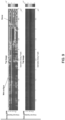
- Plot 602 shows a dry surface or pavement with no snow. From top to bottom in plot 602, responses from channels 1-11 in the SPR antenna array are shown (i.e., marked at intervals of 2, 4, 6, 8, 10 on the left side). Measurements of signal intensity are obtained and shown from from left to right, across the vehicle. The lower axis (i.e., marked 2000-16000 points) represents time, which translates into distance travelled by the vehicle. Plot 602 depicts intensity of the response from the top layer of the road (i.e., surface).
- the signal intensity measurements may translate into voltage that that is actually measured.
- the lightness and darkness of the plot 602 depicts how high the intensity of the reflection from the top of the road surface is.
- the measurement shown represents the intensity (e.g., in voltage or power) of the signal response coming off of the top of the road.
- the plots show for a vehicle equipped with a SPR antenna array being driven along a certain distance of road, for a certain time period, what the reflected signal intensity looks like.
- Surface signal reflection data may be recorded 126 times per second. Each point may represent one sweep or one set of measurements across all eleven channels. Thus, around 16000 points shown are shown. If divided by 126, the rough time period for each plot can be calculated. In some situations, data collection from the SPR antenna array may be limited. For example, if there is not enough motion from the vehicle, data may not be recorded, and the sample may be a longer time period than 1/126th of a second. For example, if the vehicle is sitting still, data may not be record.
- plots 602 and 604 On the right side of plots 602 and 604, a scale of 0, 2, 4, and 6 x 10 5 is shown. This is a measure of intensity proportional to power. By matching the colors in the scale to the colors in, for example, plot 602, it can be seen the response signal intensity if low, on the order of 1 x 10 5 . This is because plot 602 represents data from clear road surface conditions. For plot 604, which represents data from snowy road surface conditions, it can be seen that response signal intensity is relatively high, near 6 x 10 5 , with some measurements near 2 x 10 5 and 4 x 10 5 in portions of the plot. It can be seen that in plot 602, in the 12000 time-point range, a reflectional outlier was detected on the road surface. This may have been a region with water or with a metal road structure.
- surface characteristic data can be measured and passed on to vehicle control systems for use in automated vehicle control.
- Various thresholds for recognizing rain, snow, etc. can be used for acting on the surface condition data provided.
- vehicle control systems may receive raw SPR antenna data. This underlying data being used to determining the surface characteristics may be same or similar to data being used for localization applications.
- FIG. 7 shows a side cross section of the data as it penetrates the ground.
- the top part of the depth axis may be the surface of the road.
- the wet surface is shown on the top plot whereas a dry surface is shown on the bottom plot.
- the increase in intensity of the response is shown by the change in color or darkness.
- FIG. 8 shows front cross section of the data and depth versus width of an array over the 11 channels. Snow and wet surface reflections are shown on the top of the top plot. Clear conditions are shown on the bottom plot.
- FIG. 9 shows the road surface with (top) and without (bottom) snow and precipitation.
- method 100 may also include transmitting 110 one or more of the response signal, the measured intensity or phase of the response signal, and the determined surface characteristic (e.g., snow, ice, water, mud, slush, sand, and salt) to one or more control systems (e.g., vehicle control system 506) of the vehicle (e.g. vehicle 200).
- vehicle control system 506 e.g., vehicle control system 506 of the vehicle (e.g. vehicle 200).
- the response signal, the measured intensity or phase of the response signal, and/or the determined surface characteristic may be transmitted over a wired connection or wirelessly to the vehicle control system, as the vehicle control system may be in communication with the SPR processor (e.g., SPR processor 504).
- Method 100 may also include controlling 112 the vehicle (e.g., vehicle 200) based on or more of the response signal, the measured intensity or phase of the response signal, and the determined surface characteristic. Controlling the vehicle may be performed by, for example vehicle control system 506 or one or more other control systems or algorithms integrated with vehicle 200.
- the vehicle control system may be an autonomous vehicle controller or a human who is being warned of conditions or a traction control system, among others systems or variations.
- the autonomous vehicle controller or human may drive more carefully (e.g. take wider or slower turns, etc.) so as to not lose traction in slippery conditions, upon, for example, receiving a warning of the conditions.
- Controlling vehicle may include controlling the velocity, acceleration, orientation, angular velocity and/or angular acceleration of the vehicle and the vehicle may be continuously controlled via one or more vehicle navigation commands to maintain the vehicle at a desired position along a trip path or to maintain safety of the vehicle or any passengers in the vehicle, based in part on surface characteristics or surface conditions determined using the techniques and features described in the present disclosure. Controlling the vehicle may also include providing information to or assisting with traction control systems.
- Controlling the vehicle may also include individual wheel torque or traction control and a human driver may be warned and act as a result (e.g., change turn rate, etc.)
- location data for the vehicle may be used in combination with the surface characteristic data provided by the SPR system and/or one or more other sensors or navigation systems to guide or control the vehicle.
- sensor and navigation systems may include, by way of examples, an inertial navigation system (INS), a GPS, a sound navigation and ranging (SONAR) system, a LIDAR system, a camera, an inertial measurement unit (IMU) and an auxiliary radar system.
- commands generated by an autonomous vehicle navigation system may use the surface characteristic or condition data described herein to affect a vehicle path change to reduce or minimize the differences between the vehicle track and a trip path.
- the speed of the vehicle may be modified along segments of the trip path to maintain safe operation, to accommodate speed limits (e.g., which may be affected by surface conditions) and to achieve a desired completion time for traversing the trip path.
- steering, orientation, velocity, pose and acceleration/deceleration may controlled in a manner to maintain safety of the vehicle or its passengers based on the surface characteristic or condition data described here.
- the vehicle control system may include or cooperate with electrical, mechanical and pneumatic devices in the vehicle to achieve steering and speed control.
- a vehicle control system may also include or cooperate with one or more hydraulic, turbine, propeller, control surface, shape changing, and chemical systems or devices.
- real time or near real time control adjusted for various surface conditions may be achieved.
- the real time or near real time control may be achieved for autonomous vehicle navigation or control systems or manual driving systems (e.g., assisted by use of the methods and systems for determining surface characteristics described herein) to maximize safety of the vehicle and/or passengers of the vehicle in adverse road surface conditions.
- the methods and systems for determining surface characteristics described herein may also be used to collect surface information from multiple vehicles and use that prior information for controlling subsequent vehicles moving towards the same surface.
- This feature may be implemented through vehicle to vehicle communication, vehicle to structure communication, or potentially sending the surface condition information to a central surface conditions or autonomous vehicle control network and back to the vehicle desired to be controlled.
- surface-based radar signal responses may be used to determine differences between map versions where repavement has occurred. For example, when roads are repaved or resurfaced, the prior the surface may be removed and new asphalt may be applied. There may be differences in the old and new asphalt such as in density and radar signal reflections may be different.
- Surface-based radar signal responses may also be combined with other sensor data (e.g., from optical sensors) to obtain more robust data sets. As the other sensors may measure different characteristics of the surface conditions, combining the data from various sensors may allow for a more accurate and robust method of determining the surface characteristics.
Landscapes
- Engineering & Computer Science (AREA)
- Remote Sensing (AREA)
- Radar, Positioning & Navigation (AREA)
- Physics & Mathematics (AREA)
- General Physics & Mathematics (AREA)
- Computer Networks & Wireless Communication (AREA)
- Electromagnetism (AREA)
- Automation & Control Theory (AREA)
- Mechanical Engineering (AREA)
- Transportation (AREA)
- Mathematical Physics (AREA)
- Human Computer Interaction (AREA)
- Radar Systems Or Details Thereof (AREA)
- Traffic Control Systems (AREA)
- Navigation (AREA)
- Geophysics And Detection Of Objects (AREA)
- Investigating Or Analysing Materials By Optical Means (AREA)
- Measurement Of Resistance Or Impedance (AREA)
Claims (13)
- Verfahren (100) zum Steuern der Navigation eines Fahrzeugs, wobei das Verfahren umfasst:Übertragen (102) eines Oberflächen durchdringenden Radarsignals (SPR) von einem SPR-System an einem Fahrzeug in Richtung einer Oberfläche;Empfangen (104) eines Antwortsignals am SPR-System, wobei das Antwortsignal eine Reflexion des SPR-Signals von einem der Oberfläche zugeordneten Oberflächenbereich und eine Reflexion des SPR-Signals von einem Randschichtbereich einschließt;Messen (106) einer Intensität und/oder einer Phase des Antwortsignals;Bestimmen (108), zumindest teilweise basierend auf mindestens einem von der Intensität und der Phase des Antwortsignals, einer Oberflächeneigenschaft der Oberfläche und von Ortsbestimmungsdaten für das Fahrzeug; undSteuern (112) einer Navigation des Fahrzeugs basierend auf mindestens einem von: dem Antwortsignal, der gemessenen Intensität des Antwortsignals, der gemessenen Phase des Antwortsignals, der bestimmten Oberflächeneigenschaft und den bestimmten Ortsbestimmungsdaten, wobeidie Oberflächeneigenschaft mindestens eine ist von Schnee, Eis, Wasser, Schlamm, Matsch, Sand, Kies, Schmutz, Steinen, Schutt und Salz.
- Verfahren nach Anspruch 1, ferner umfassend:
Senden (110) von mindestens einem von: dem Antwortsignal, der gemessenen Intensität des Antwortsignals, der gemessenen Phase des Antwortsignals, der bestimmten Oberflächeneigenschaft und den bestimmten Ortsbestimmungsdaten an ein oder mehrere Steuersysteme des Fahrzeugs. - Verfahren nach Anspruch 1, wobei das Bestimmen (114) der Oberflächeneigenschaft auf mindestens einem von einer Übertragungsfunktion und einer Frequenzantwort basiert.
- Verfahren nach Anspruch 1, wobei das Bestimmen der Oberflächeneigenschaft umfasst:
Korrelieren (116) der gemessenen Intensität oder Phase des Antwortsignals mit bekannten Intensitäten oder Phasen von Signalantworten, die einer Vielzahl von vordefinierten Oberflächeneigenschaften zugeordnet sind. - Verfahren nach Anspruch 1, wobei das Bestimmen der Oberflächeneigenschaft umfasst: Berechnen (118) von mindestens einem von:einer Differenz zwischen einer bekannten Intensität oder Phase einer Eigenschaft einer klaren Oberfläche und der gemessenen Intensität oder Phase des Antwortsignals; undeiner Differenz zwischen einer bekannten Intensität oder Phase einer Oberflächeneigenschaft des Niederschlagszustands und der gemessenen Intensität des Antwortsignals.
- Verfahren nach Anspruch 1, wobei das Bestimmen der Oberflächeneigenschaft umfasst:Korrelieren der gemessenen Intensität oder Phase des Antwortsignals mit bekannten Intensitäten oder Phasen von Signalantworten, die einer Vielzahl von vordefinierten Oberflächeneigenschaften zugeordnet sind; undBerechnen von mindestens einem von:einer Differenz zwischen einer bekannten Intensität oder Phase einer Eigenschaft einer klaren Oberfläche und der gemessenen Intensität des Antwortsignals; undeiner Differenz zwischen einer bekannten Intensität oder Phase einer Oberflächeneigenschaft des Niederschlagszustands und der gemessenen Intensität des Antwortsignals.
- Verfahren nach Anspruch 1, wobei die gemessene Intensität des Antwortsignals mindestens eines von einer Spannung und einer Leistung ist.
- Verfahren nach Anspruch 1, wobei das SPR-System eine Vielzahl von unter dem Fahrzeug positionierten SPR-Antennen und -Kanälen umfasst, wobei jeder Kanal mindestens ein Sendeelement und mindestens ein Empfangselement umfasst.
- Verfahren nach Anspruch 1, wobei das Bestimmen (120) der Oberflächeneigenschaft das Verwenden von mindestens einem von dem Antwortsignal und der gemessenen Intensität oder Phase des Antwortsignals und einer Ausgabe eines anderen Sensors umfasst; und
wobei der Sensor vorzugsweise einem oder mehreren der folgenden zugeordnet ist: einem optischen Sensor, einem Trägheitsnavigationssystem (INS), einem GPS, einem SONAR-System (SONAR), einem LIDAR-System, einer Kamera, einer Trägheitsmesseinheit (IMU), einem Radschlupfsensor/-encoder und einem zusätzlichen Radarsystem. - System zum Bestimmen von Oberflächeneigenschaften und Ortsbestimmungsdaten für ein Fahrzeug, wobei das System umfasst:mindestens einen SPR-Kanal, der mindestens ein SPR-Sendeelement und mindestens ein SPR-Empfangselement umfasst;einen SPR-Prozessor (504), der mit dem mindestens einen SPR-Empfangselement in Kommunikationsverbindung steht, wobei der SPR-Prozessor als Reaktion auf den Empfang eines Antwortsignals vom SPR-Empfangselement:mindestens eines von einer Intensität und einer Phase des am SPR-Empfangselement empfangenen Antwortsignals misst (106), wobei das Antwortsignal eine Reflexion eines gesendeten SPR-Signals von einem Oberflächenbereich, der einer Oberfläche zugeordnet ist, und eine Reflexion des gesendeten SPR-Signals von einem Randschichtbereich einschließt; undzumindest teilweise basierend auf der Intensität oder der Phase des Antwortsignals eine Oberflächeneigenschaft der Oberfläche und Ortsbestimmungsdaten für das Fahrzeug bestimmt (108); undein Fahrzeugsteuerungssystem (506) in Kommunikationsverbindung mit dem SPR-Prozessor, wobei das Fahrzeugsteuerungssystem eine Navigation des Fahrzeugs basierend auf mindestens einem der folgenden steuert: dem Antwortsignal, der gemessenen Intensität des Antwortsignals, der gemessenen Phase des Antwortsignals, der bestimmten Oberflächeneigenschaft und den bestimmten Ortsbestimmungsdaten, wobeidie Oberflächeneigenschaft mindestens eine ist von Schnee, Eis, Wasser, Schlamm, Matsch, Sand, Kies, Schmutz, Steinen, Schutt und Salz.
- System nach Anspruch 10, wobei der SPR-Prozessor konfiguriert ist zum:
Senden (110) von mindestens einem von: dem Antwortsignal, der gemessenen Intensität des Antwortsignals, der gemessenen Phase des Antwortsignals, der bestimmten Oberflächeneigenschaft und den bestimmten Ortsbestimmungsdaten an ein oder mehrere Steuersysteme des Fahrzeugs. - SPR-System nach Anspruch 10, wobei:
der mindestens eine SPR-Kanal eine Vielzahl von SPR-Kanälen ist, die aus einem unter einem Fahrzeug positionierbaren SPR-Antennenarray gebildet sind, wobei jeder SPR-Kanal ein SPR-Antennenpaar umfasst, wobei eine SPR-Antenne des SPR-Antennenpaars eine SPR-Sendeantenne und die andere SPR-Antenne des SPR-Antennenpaars eine SPR-Empfangsantenne ist. - SPR-System nach Anspruch 12, wobei beliebiges der folgenden gilt:ein erster SPR-Kanal umfasst eine erste SPR-Sendeantenne, die hinter einem vorderen Reifen auf der Fahrerseite eines Fahrzeugs positionierbar ist, und eine erste SPR-Empfangsantenne, die im Wesentlichen parallel zur ersten SPR-Sendeantenne in Richtung eines vorderen Reifens auf der Beifahrerseite des Fahrzeugs positionierbar ist;die SPR-Antennenpaare des SPR-Antennenarrays sind im Wesentlichen parallel zueinander positionierbar und das SPR-Antennenarray ist so positionierbar, dass es sich von hinter dem vorderen Reifen auf der Fahrerseite eines Fahrzeugs in Richtung eines vorderen Reifens auf der Beifahrerseite des Fahrzeugs erstreckt; unddie SPR-Antennen sind der Länge nach entlang einer Länge des Fahrzeugs von hinter dem vorderen Reifen auf der Fahrerseite eines Fahrzeugs in Richtung eines hinteren Reifens auf der Fahrerseite des Fahrzeugs positionierbar.
Applications Claiming Priority (3)
| Application Number | Priority Date | Filing Date | Title |
|---|---|---|---|
| US201762451313P | 2017-01-27 | 2017-01-27 | |
| US201762529740P | 2017-07-07 | 2017-07-07 | |
| PCT/US2018/015775 WO2018140893A1 (en) | 2017-01-27 | 2018-01-29 | Determining surface characteristics |
Publications (4)
| Publication Number | Publication Date |
|---|---|
| EP3574288A1 EP3574288A1 (de) | 2019-12-04 |
| EP3574288A4 EP3574288A4 (de) | 2020-12-09 |
| EP3574288C0 EP3574288C0 (de) | 2025-06-18 |
| EP3574288B1 true EP3574288B1 (de) | 2025-06-18 |
Family
ID=62977304
Family Applications (4)
| Application Number | Title | Priority Date | Filing Date |
|---|---|---|---|
| EP17894510.1A Active EP3574340B1 (de) | 2017-01-27 | 2017-12-04 | Verfahren und system zur lokalisierung eines fahrzeugs unter verwendung eines oberflächenpenetrierenden radars |
| EP18744920.2A Active EP3574341B1 (de) | 2017-01-27 | 2018-01-29 | Erweiterter footprint zur lokalisierung mithilfe von oberflächenpenetrierendem radar (spr) |
| EP18744057.3A Active EP3574288B1 (de) | 2017-01-27 | 2018-01-29 | Bestimmung von oberflächeneigenschaften |
| EP22181645.7A Pending EP4086577A1 (de) | 2017-01-27 | 2018-01-29 | Erweiterter footprint zur lokalisierung mithilfe von oberflächenpenetrierendem radar (spr) |
Family Applications Before (2)
| Application Number | Title | Priority Date | Filing Date |
|---|---|---|---|
| EP17894510.1A Active EP3574340B1 (de) | 2017-01-27 | 2017-12-04 | Verfahren und system zur lokalisierung eines fahrzeugs unter verwendung eines oberflächenpenetrierenden radars |
| EP18744920.2A Active EP3574341B1 (de) | 2017-01-27 | 2018-01-29 | Erweiterter footprint zur lokalisierung mithilfe von oberflächenpenetrierendem radar (spr) |
Family Applications After (1)
| Application Number | Title | Priority Date | Filing Date |
|---|---|---|---|
| EP22181645.7A Pending EP4086577A1 (de) | 2017-01-27 | 2018-01-29 | Erweiterter footprint zur lokalisierung mithilfe von oberflächenpenetrierendem radar (spr) |
Country Status (6)
| Country | Link |
|---|---|
| US (4) | US10725171B2 (de) |
| EP (4) | EP3574340B1 (de) |
| JP (5) | JP6837690B2 (de) |
| CN (4) | CN110520754B (de) |
| ES (3) | ES2984945T3 (de) |
| WO (3) | WO2018140134A2 (de) |
Families Citing this family (37)
| Publication number | Priority date | Publication date | Assignee | Title |
|---|---|---|---|---|
| DE102014221888A1 (de) * | 2014-10-28 | 2016-04-28 | Robert Bosch Gmbh | Verfahren und Vorrichtung zur Lokalisierung eines Fahrzeugs in seinem Umfeld |
| US10725171B2 (en) | 2017-01-27 | 2020-07-28 | Massachusetts Institute Of Technology | Method and system for localization of a vehicle using surface penetrating radar |
| US11400956B2 (en) | 2017-02-23 | 2022-08-02 | Richard Anthony Bishel | Vehicle guidance system |
| IT201700047233A1 (it) * | 2017-05-02 | 2018-11-02 | Ids Georadar S R L | Metodo perfezionato per l’esecuzione di indagini georadar e relativa apparecchiatura |
| HUE065606T2 (hu) | 2017-09-01 | 2024-06-28 | Massachusetts Inst Technology | Felszínen áthatoló radar- és akkumulátorrendszerek |
| US11150342B2 (en) | 2017-09-07 | 2021-10-19 | Magna Electronics Inc. | Vehicle radar sensing system with surface segmentation using interferometric statistical analysis |
| US10962638B2 (en) * | 2017-09-07 | 2021-03-30 | Magna Electronics Inc. | Vehicle radar sensing system with surface modeling |
| US10852423B2 (en) * | 2018-03-07 | 2020-12-01 | The Government Of The United States, As Represented By The Secretary Of The Army | Vehicle-mounted wave transmission and wave response reception |
| US20190339362A1 (en) * | 2018-05-03 | 2019-11-07 | Mediatek Inc. | Signature-based object detection method and associated apparatus |
| CN108549301B (zh) * | 2018-06-11 | 2020-09-18 | 南京邮电大学南通研究院有限公司 | 一种超宽带探地雷达控制系统 |
| US11059489B2 (en) * | 2018-10-24 | 2021-07-13 | Valeo Radar Systems, Inc. | Methods and systems for detecting road surface conditions |
| CN109709556B (zh) * | 2018-12-24 | 2021-02-19 | 雷象科技(北京)有限公司 | 相控阵天气雷达多因子关联去地物方法 |
| EP3942382A4 (de) * | 2019-03-19 | 2022-12-28 | Clearmotion, Inc. | Fahrzeuglokalisierungssystem, verfahren und steuerungen |
| US11543514B2 (en) * | 2019-03-29 | 2023-01-03 | Elemenf Hope, Inc. | Activity detection in sand environment |
| JP7211605B2 (ja) * | 2019-07-15 | 2023-01-24 | ウェーブセンス, インコーポレイテッド | 地形を考慮したルート計画 |
| US20210026373A1 (en) * | 2019-07-22 | 2021-01-28 | Daniel Jamison | Vehicle platooning using surface-penetrating radar systems |
| US11867798B2 (en) * | 2019-09-13 | 2024-01-09 | Samsung Electronics Co., Ltd. | Electronic device including sensor and method of determining path of electronic device |
| US11579286B2 (en) * | 2019-09-13 | 2023-02-14 | Wavesense, Inc. | Navigation and localization using surface-penetrating radar and deep learning |
| RU2727087C1 (ru) * | 2019-09-13 | 2020-07-17 | Самсунг Электроникс Ко., Лтд. | Сенсор spr (радар подповерхностного зондирования) для помощи в осуществлении навигации технического устройства |
| US11754702B2 (en) | 2019-09-18 | 2023-09-12 | Thales Canada Inc. | Method and system for high-integrity vehicle localization and speed determination |
| WO2021072168A1 (en) | 2019-10-09 | 2021-04-15 | Wavesense, Inc. | Micro-antenna arrays |
| EP4010732A4 (de) * | 2019-10-18 | 2022-10-05 | Wavesense, Inc. | Schwingungserkennung für fahrzeuge und anhänger |
| CN111175742B (zh) * | 2020-01-17 | 2021-11-19 | 中国矿业大学(北京) | “钟摆式”探地雷达数据采集装置 |
| US11150341B2 (en) * | 2020-02-18 | 2021-10-19 | HG Partners, LLC | Continuous-wave radar system for detecting ferrous and non-ferrous metals in saltwater environments |
| US11960000B2 (en) * | 2020-02-18 | 2024-04-16 | HG Partners, LLC | Continuous-wave radar system for detecting ferrous and non-ferrous metals in saltwater environments |
| US11686839B1 (en) * | 2020-02-18 | 2023-06-27 | HG Partners, LLC | Continuous-wave radar system for detecting ferrous and non-ferrous metals in saltwater environments |
| US12210092B1 (en) | 2020-02-18 | 2025-01-28 | HG Partners, LLC | Continuous-wave radar system for detecting ferrous and non-ferrous metals in saltwater environments |
| CN116324496A (zh) * | 2020-07-23 | 2023-06-23 | Gpr公司 | 使用表面穿透雷达系统和多普勒频移监测车辆运动 |
| CN116457693A (zh) * | 2020-09-21 | 2023-07-18 | Gpr公司 | 使用表面穿透雷达系统和广播传输监测车辆位置 |
| JP6960129B1 (ja) * | 2020-12-21 | 2021-11-05 | WaveArrays株式会社 | レーダ装置 |
| US12066571B2 (en) | 2021-05-03 | 2024-08-20 | Waymo Llc | Methods and systems for detecting adverse road conditions using radar |
| CN114002648A (zh) * | 2021-09-14 | 2022-02-01 | 广西电网有限责任公司南宁供电局 | 一种带有反干扰效果的电缆识别用探地雷达车 |
| CN115015899B (zh) * | 2022-04-19 | 2025-07-11 | 合众新能源汽车股份有限公司 | 一种定位方法、装置及电子设备 |
| EP4515474A1 (de) * | 2022-04-28 | 2025-03-05 | GPR, Inc. | Transaktionsverarbeitung mit oberflächenpenetrierendem radar |
| AU2023299798A1 (en) * | 2022-06-24 | 2024-12-05 | HG Partners, LLC | Continuous-wave radar system for detecting ferrous and non-ferrous metals in saltwater environments |
| US20240045054A1 (en) * | 2022-08-03 | 2024-02-08 | Geophysical Survey Systems, Inc. | Method of Generating a Map Based on Ground Penetrating Radar Scans |
| SE2330191A1 (en) | 2023-05-01 | 2024-11-02 | Volvo Truck Corp | Radar-based wheel end modules for determining wheel force generating capability |
Citations (1)
| Publication number | Priority date | Publication date | Assignee | Title |
|---|---|---|---|---|
| US20140121964A1 (en) * | 2012-10-25 | 2014-05-01 | Massachusetts Institute Of Technology | Vehicle localization using surface penetrating radar |
Family Cites Families (101)
| Publication number | Priority date | Publication date | Assignee | Title |
|---|---|---|---|---|
| US3366960A (en) | 1966-11-01 | 1968-01-30 | Gen Precision Systems Inc | Microwave radiometric navigation system |
| JPS5935108B2 (ja) | 1975-02-19 | 1984-08-27 | ヤマハ株式会社 | トレ−スア−ムの制御装置 |
| US4162509A (en) | 1978-06-21 | 1979-07-24 | The United States Of America As Represented By The Secretary Of The Army | Non-contact velocimeter using arrays |
| GB2025673B (en) * | 1978-06-28 | 1983-04-27 | Westinghouse Electric Corp | Desired velocitycontrol for railway vehicles |
| US4671650A (en) | 1982-09-20 | 1987-06-09 | Crane Co. (Hydro-Aire Division) | Apparatus and method for determining aircraft position and velocity |
| US4495589A (en) | 1982-09-20 | 1985-01-22 | Crane Co. | Aircraft ground velocity determination system |
| JPS6193969A (ja) * | 1984-10-15 | 1986-05-12 | Hitachi Ltd | 埋設物探知装置 |
| US5202692A (en) | 1986-06-16 | 1993-04-13 | Millitech Corporation | Millimeter wave imaging sensors, sources and systems |
| US4846297A (en) * | 1987-09-28 | 1989-07-11 | Tennant Company | Automated guided vehicle |
| JPH0227286A (ja) * | 1988-07-18 | 1990-01-30 | Hitachi Shonan Denshi Co Ltd | 地中レーダのサンプリング方法とサンプリング装置 |
| DE4040842A1 (de) * | 1990-08-04 | 1992-02-06 | Telefunken Systemtechnik | Infrarot-mikrowellen-sensorsystem zur erkennung des fahrbahnzustandes |
| FR2695202B1 (fr) | 1992-09-03 | 1994-11-10 | Aerospatiale | Système embarqué de navigation pour un engin aérien comportant un radar à visée latérale et à synthèse d'ouverture. |
| US5497100A (en) * | 1994-10-17 | 1996-03-05 | Hughes Aircraft Company | Surface condition sensing system |
| US5684490A (en) * | 1995-03-01 | 1997-11-04 | The Ohio State University | Highway vehicle guidance system |
| US6370475B1 (en) | 1997-10-22 | 2002-04-09 | Intelligent Technologies International Inc. | Accident avoidance system |
| US7400267B1 (en) | 1995-06-08 | 2008-07-15 | Western Strategic Products, Llc | Methods for determining need for treating a vehicle travel surface |
| JPH0953939A (ja) | 1995-08-18 | 1997-02-25 | Fujitsu Ltd | 自走車の自己位置測定装置および自己位置測定方法 |
| US5673050A (en) * | 1996-06-14 | 1997-09-30 | Moussally; George | Three-dimensional underground imaging radar system |
| JPH10104346A (ja) * | 1996-09-27 | 1998-04-24 | Fujitsu Ten Ltd | 車両位置検出装置および方法 |
| JPH10103964A (ja) * | 1996-09-27 | 1998-04-24 | Fujitsu Ten Ltd | 車両位置検出装置および方法 |
| US5999866A (en) | 1996-11-05 | 1999-12-07 | Carnegie Mellon University | Infrastructure independent position determining system |
| US6082466A (en) | 1998-10-28 | 2000-07-04 | Caterpillar Inc. | Rowcrop machine guidance using ground penetrating radar |
| US6377872B1 (en) * | 1999-07-02 | 2002-04-23 | Bae Systems Information And Electronic Systems Integration Inc | Apparatus and method for microwave imaging and excavation of objects |
| JP4120114B2 (ja) * | 1999-11-04 | 2008-07-16 | 株式会社デンソー | 路面状況推定装置 |
| NL1013661C2 (nl) * | 1999-11-24 | 2001-06-14 | Univ Delft Tech | Gronddoordringende radarinrichting en werkwijze voor het detecteren van een object op of onder een grondoppervlak. |
| AUPQ592600A0 (en) * | 2000-02-29 | 2000-03-23 | Cea Technologies Inc. | Ground penetrating radar |
| JP3607159B2 (ja) | 2000-04-06 | 2005-01-05 | 株式会社ケンウッド | ナビゲーションシステム、マップマッチング方法および記録媒体 |
| US6362775B1 (en) | 2000-04-25 | 2002-03-26 | Mcdonnell Douglas Corporation | Precision all-weather target location system |
| US6445334B1 (en) * | 2000-12-29 | 2002-09-03 | Planning Systems Incorporated | Ground penetrating radar system |
| AU2002255746A1 (en) | 2001-03-14 | 2002-09-24 | Witten Technologies Inc. | Method for merging position and measurement information |
| JP4129419B2 (ja) * | 2002-08-01 | 2008-08-06 | 名古屋電機工業株式会社 | 路面状態判別方法およびその装置 |
| US6963301B2 (en) | 2002-08-19 | 2005-11-08 | G-Track Corporation | System and method for near-field electromagnetic ranging |
| US6917368B2 (en) * | 2003-03-04 | 2005-07-12 | Clairvoyante, Inc. | Sub-pixel rendering system and method for improved display viewing angles |
| DK1890128T3 (da) | 2003-03-14 | 2012-03-19 | Liwas Aps | Anordning til detektering af vejoverfladetilstand |
| DK1735637T3 (en) | 2004-04-05 | 2019-04-29 | Weibel Scient A/S | System and method for radar detection of an object. |
| US7167126B2 (en) | 2004-09-01 | 2007-01-23 | The Boeing Company | Radar system and method for determining the height of an object |
| US20060095172A1 (en) | 2004-10-28 | 2006-05-04 | Abramovitch Daniel Y | Optical navigation system for vehicles |
| US7191056B2 (en) | 2005-01-04 | 2007-03-13 | The Boeing Company | Precision landmark-aided navigation |
| JP2006208223A (ja) | 2005-01-28 | 2006-08-10 | Aisin Aw Co Ltd | 車両位置認識装置及び車両位置認識方法 |
| JP4158778B2 (ja) * | 2005-03-28 | 2008-10-01 | 株式会社日立製作所 | ハイドロプレーニング状態判定装置 |
| US7528762B2 (en) * | 2005-03-31 | 2009-05-05 | Southwest Research Institute | Signal processing methods for ground penetrating radar from elevated platforms |
| US7395156B2 (en) | 2005-06-23 | 2008-07-01 | Raytheon Company | System and method for geo-registration with global positioning and inertial navigation |
| US7755360B1 (en) * | 2005-10-24 | 2010-07-13 | Seektech, Inc. | Portable locator system with jamming reduction |
| EP1783517A1 (de) * | 2005-11-04 | 2007-05-09 | AGELLIS Group AB | Multi-dimensionale Abbildungsmethode und Apparat |
| US7417586B2 (en) | 2006-02-07 | 2008-08-26 | Honeywell International Inc. | Methods and systems for interferometric cross track phase calibration |
| US8089390B2 (en) * | 2006-05-16 | 2012-01-03 | Underground Imaging Technologies, Inc. | Sensor cart positioning system and method |
| US20100026555A1 (en) | 2006-06-09 | 2010-02-04 | Whittaker William L | Obstacle detection arrangements in and for autonomous vehicles |
| JP2008090599A (ja) * | 2006-10-02 | 2008-04-17 | Mitsubishi Electric Corp | 地中埋設設備の情報読み取り装置 |
| JP4481316B2 (ja) | 2007-01-09 | 2010-06-16 | 株式会社エヌ・ティ・ティ・ドコモ | ユーザ装置および送信方法 |
| US8306747B1 (en) | 2007-01-19 | 2012-11-06 | Starodub, Inc. | Travel way measurement system |
| DE102007039897B3 (de) | 2007-08-23 | 2008-10-16 | Universität Karlsruhe (Th) | Verfahren zum Betrieb einer Antennengruppe mit mehreren Sendern und mehreren Empfängern sowie zugehörige Vorrichtung |
| US8207885B2 (en) * | 2007-09-19 | 2012-06-26 | Niitek, Inc. | Adjustable pulse width ground penetrating radar |
| CL2008000024A1 (es) * | 2008-01-04 | 2009-01-16 | Univ Pontificia Catolica Chile | Sistema y metodo para la deteccion, localizacion e identificacion de objetos en suelo y subsuelo que se encuentran en un area de interes previamente referenciada. |
| JP4533936B2 (ja) | 2008-02-01 | 2010-09-01 | 日立オートモティブシステムズ株式会社 | 画像処理装置、及びこれを備えた車両検知装置 |
| JP5574579B2 (ja) | 2008-05-29 | 2014-08-20 | アルパイン株式会社 | レーダ監視装置 |
| WO2009155999A1 (en) * | 2008-06-25 | 2009-12-30 | Tomtom International B.V. | Navigation apparatus and method of route configuration |
| WO2010014859A2 (en) * | 2008-07-30 | 2010-02-04 | Sal Amarillas | Device and method to evaluate condition of concrete roadways employing a radar-based sensing and data acquisition system |
| JP2010164521A (ja) * | 2009-01-19 | 2010-07-29 | Sumitomo Electric Ind Ltd | 路面状況判別装置 |
| RU2009108360A (ru) | 2009-03-10 | 2010-09-20 | Михаил Юрьевич Воробьев (RU) | Способ измерения движения видеокамеры относительно поверхности и устройство для его осуществления |
| JP4442914B1 (ja) * | 2009-07-30 | 2010-03-31 | ジオ・サーチ株式会社 | 舗装の内部損傷箇所の非破壊調査方法 |
| US8169362B2 (en) | 2009-08-03 | 2012-05-01 | Raytheon Company | Mobile sense through the wall radar system |
| WO2011047730A1 (en) | 2009-10-22 | 2011-04-28 | Tele Atlas B.V. | System and method for vehicle navigation using lateral offsets |
| US8115667B2 (en) * | 2009-11-17 | 2012-02-14 | Geophysical Survey Systems, Inc. | Highway speed ground penetrating radar system utilizing air-launched antenna and method of use |
| WO2011116375A1 (en) | 2010-03-19 | 2011-09-22 | Northeastern University | Roaming mobile sensor platform for collecting geo-referenced data and creating thematic maps |
| US8847813B2 (en) * | 2010-06-15 | 2014-09-30 | Stolar Research Corporation | Unsynchronized radio imaging |
| US8730084B2 (en) * | 2010-11-29 | 2014-05-20 | King Abdulaziz City For Science And Technology | Dual mode ground penetrating radar (GPR) |
| CN102176011B (zh) * | 2011-01-24 | 2014-01-01 | 陕西延长石油(集团)有限责任公司 | 一种近场条件下的探地雷达三维相干成像方法 |
| US9562778B2 (en) | 2011-06-03 | 2017-02-07 | Robert Bosch Gmbh | Combined radar and GPS localization system |
| US9946937B2 (en) * | 2011-06-17 | 2018-04-17 | Robert Bosch Gmbh | Method and control unit for recognizing a weather condition in the surroundings of a vehicle |
| US8786485B2 (en) * | 2011-08-30 | 2014-07-22 | Masachusetts Institute Of Technology | Mobile coherent change detection ground penetrating radar |
| US20130113648A1 (en) * | 2011-09-30 | 2013-05-09 | L-3 Communications Cyterra Corporation | Sensor head |
| US9207316B2 (en) | 2011-11-21 | 2015-12-08 | Stolar, Inc. | Radar for rejecting and looking past surface reflections |
| US9168924B2 (en) * | 2012-03-26 | 2015-10-27 | GM Global Technology Operations LLC | System diagnosis in autonomous driving |
| US8957809B2 (en) * | 2012-07-18 | 2015-02-17 | Geophysical Survey Systems, Inc. | Merged ground penetrating radar display for multiple antennas |
| US9499172B2 (en) | 2012-09-20 | 2016-11-22 | Google Inc. | Detecting road weather conditions |
| US8994581B1 (en) | 2012-09-25 | 2015-03-31 | Adam Brown | Direction of arrival (DOA) estimation using multiple offset receive channels |
| US9140786B2 (en) * | 2012-12-07 | 2015-09-22 | Harris Corporation | Method and system using radiometric volumetric data for detecting oil covered by ice |
| EP2972252B1 (de) | 2013-03-14 | 2023-10-18 | Robert Ernest Troxler | Systeme und verfahren zur bodeneigenschaften- und bodenfeuchtigkeitsmessung mit einem bodendurchdringenden radar |
| GB201308807D0 (en) * | 2013-05-16 | 2013-07-03 | Jaguar Land Rover Ltd | Vehicle traction control |
| US8849523B1 (en) * | 2013-05-20 | 2014-09-30 | Elwha Llc | Systems and methods for detecting soil characteristics |
| US9395437B2 (en) | 2013-06-06 | 2016-07-19 | The United States Of America, As Represented By The Secretary Of The Army | Moving multi-polarization multi-transmitter/receiver ground penetrating radar system and signal processing for buried target detection |
| EP3004374B1 (de) * | 2013-06-07 | 2020-08-12 | Massachusetts Institute of Technology | Affinitätsbasierter nachweis von ligandencodierten synthetischen biomarkern |
| CN104597442A (zh) * | 2013-11-01 | 2015-05-06 | 无锡慧思顿科技有限公司 | 高速成像超宽带探地雷达车 |
| US9541641B2 (en) | 2014-01-08 | 2017-01-10 | Stolar, Inc. | Method of electronically mapping underground utility infrastructures from the surface |
| US10576907B2 (en) * | 2014-05-13 | 2020-03-03 | Gse Technologies, Llc | Remote scanning and detection apparatus and method |
| CN204101725U (zh) * | 2014-10-30 | 2015-01-14 | 厦门大学 | 一种混合极化双通道探地雷达系统 |
| US9892296B2 (en) * | 2014-11-12 | 2018-02-13 | Joseph E. Kovarik | Method and system for autonomous vehicles |
| KR102263725B1 (ko) * | 2014-11-21 | 2021-06-11 | 현대모비스 주식회사 | 주행 정보 제공 장치 및 주행 정보 제공 방법 |
| US9453941B2 (en) * | 2014-12-22 | 2016-09-27 | GM Global Technology Operations LLC | Road surface reflectivity detection by lidar sensor |
| JP5935108B1 (ja) * | 2015-01-29 | 2016-06-15 | 防衛装備庁長官 | 前方側方同時監視型地中レーダ装置 |
| CN104793203B (zh) * | 2015-04-17 | 2017-03-29 | 中南大学 | 一种用于多频多通道探地雷达的数据融合方法 |
| AU2016261331B2 (en) | 2015-05-08 | 2021-03-25 | Climate Llc | Work layer imaging and analysis for implement monitoring, control and operator feedback |
| US10809372B2 (en) * | 2015-05-11 | 2020-10-20 | Vayyar Imaging Ltd. | System, device and methods for imaging of objects using electromagnetic array |
| CN104808202A (zh) * | 2015-05-11 | 2015-07-29 | 粟毅 | 一种表层穿透雷达成像方法及装置 |
| CN105182328B (zh) * | 2015-09-09 | 2017-08-25 | 河南工业大学 | 一种基于二维经验模态分解的探地雷达地下目标检测方法 |
| US10222465B2 (en) * | 2015-12-29 | 2019-03-05 | Geophysical Survey Systems, Inc. | Magnetic field detector and ground-penetrating radar device with merged display |
| CN205406704U (zh) * | 2016-03-09 | 2016-07-27 | 江苏省交通规划设计院股份有限公司 | 一种探地雷达低频组合天线的多功能辅助装置 |
| CN106114501B (zh) * | 2016-06-23 | 2018-10-12 | 吉林大学 | 一种具有多模式的基于线控转向的换道避撞控制方法 |
| CN106226780B (zh) * | 2016-07-26 | 2019-02-05 | 南京航空航天大学 | 基于激光扫描雷达的多旋翼室内定位系统及实现方法 |
| CN106291540A (zh) * | 2016-09-14 | 2017-01-04 | 河北省电力勘测设计研究院 | 一种基于doa估计的多输入多输出探地雷达逆向投影目标成像方法 |
| US10725171B2 (en) | 2017-01-27 | 2020-07-28 | Massachusetts Institute Of Technology | Method and system for localization of a vehicle using surface penetrating radar |
-
2017
- 2017-12-04 US US15/830,398 patent/US10725171B2/en active Active
- 2017-12-04 JP JP2019539213A patent/JP6837690B2/ja active Active
- 2017-12-04 ES ES17894510T patent/ES2984945T3/es active Active
- 2017-12-04 EP EP17894510.1A patent/EP3574340B1/de active Active
- 2017-12-04 CN CN201780089188.3A patent/CN110520754B/zh active Active
- 2017-12-04 WO PCT/US2017/064458 patent/WO2018140134A2/en not_active Ceased
-
2018
- 2018-01-29 CN CN202410358763.7A patent/CN118244264A/zh active Pending
- 2018-01-29 EP EP18744920.2A patent/EP3574341B1/de active Active
- 2018-01-29 US US15/882,889 patent/US10746867B2/en active Active
- 2018-01-29 WO PCT/US2018/015791 patent/WO2018140897A1/en not_active Ceased
- 2018-01-29 ES ES18744920T patent/ES2928098T3/es active Active
- 2018-01-29 CN CN201880022449.4A patent/CN110462433B/zh active Active
- 2018-01-29 ES ES18744057T patent/ES3035588T3/es active Active
- 2018-01-29 US US15/882,986 patent/US10663579B2/en active Active
- 2018-01-29 EP EP18744057.3A patent/EP3574288B1/de active Active
- 2018-01-29 WO PCT/US2018/015775 patent/WO2018140893A1/en not_active Ceased
- 2018-01-29 JP JP2019539239A patent/JP6980301B2/ja active Active
- 2018-01-29 JP JP2019539238A patent/JP6989152B2/ja active Active
- 2018-01-29 CN CN201880022492.0A patent/CN110494714B/zh active Active
- 2018-01-29 EP EP22181645.7A patent/EP4086577A1/de active Pending
-
2020
- 2020-07-20 US US16/933,291 patent/US11402493B2/en active Active
-
2021
- 2021-11-10 JP JP2021183062A patent/JP2022024024A/ja active Pending
-
2023
- 2023-10-06 JP JP2023174695A patent/JP2024001209A/ja active Pending
Patent Citations (1)
| Publication number | Priority date | Publication date | Assignee | Title |
|---|---|---|---|---|
| US20140121964A1 (en) * | 2012-10-25 | 2014-05-01 | Massachusetts Institute Of Technology | Vehicle localization using surface penetrating radar |
Also Published As
Similar Documents
| Publication | Publication Date | Title |
|---|---|---|
| US11402493B2 (en) | Determining surface characteristics | |
| JP7258125B2 (ja) | 受動型赤外線誘導システム | |
| Ort et al. | Autonomous navigation in inclement weather based on a localizing ground penetrating radar | |
| US8949024B2 (en) | Vehicle localization using surface penetrating radar | |
| KR101454153B1 (ko) | 가상차선과 센서 융합을 통한 무인 자율주행 자동차의 항법시스템 | |
| KR102089706B1 (ko) | 다른 차량의 자국들의 세트에 기초하여 도로의 스트레치를 추정하기 위한 차량의 방법 및 제어 유닛 | |
| WO2018054910A2 (en) | Method and arrangement for determining a condition of a road surface | |
| Lhomme-Desages et al. | Doppler-based ground speed sensor fusion and slip control for a wheeled rover | |
| EP3508861A1 (de) | Geschwindigkeitsberechnungsvorrichtung, steuerungsverfahren, programm und speichermedium | |
| Ringdahl et al. | Estimating wheel slip for a forest machine using RTK-DGPS | |
| Abosekeen et al. | Utilizing the ACC-FMCW radar for land vehicles navigation | |
| JP2021113047A (ja) | 移動体制御装置、移動体制御方法、および、移動体制御装置用プログラム | |
| HK40017241A (en) | Determining surface characteristics | |
| HK40017241B (zh) | 确定表面特徵 | |
| US20190086936A1 (en) | Surface Movement Awareness System - Commercial | |
| US20250018934A1 (en) | Automated parking control device | |
| US20230266471A1 (en) | Method for localizing and/or mapping during operation of a vehicle in an environment | |
| HK40017240A (en) | Extending footprint for localization using surface penetrating radar (spr) |
Legal Events
| Date | Code | Title | Description |
|---|---|---|---|
| STAA | Information on the status of an ep patent application or granted ep patent |
Free format text: STATUS: THE INTERNATIONAL PUBLICATION HAS BEEN MADE |
|
| PUAI | Public reference made under article 153(3) epc to a published international application that has entered the european phase |
Free format text: ORIGINAL CODE: 0009012 |
|
| STAA | Information on the status of an ep patent application or granted ep patent |
Free format text: STATUS: REQUEST FOR EXAMINATION WAS MADE |
|
| 17P | Request for examination filed |
Effective date: 20190812 |
|
| AK | Designated contracting states |
Kind code of ref document: A1 Designated state(s): AL AT BE BG CH CY CZ DE DK EE ES FI FR GB GR HR HU IE IS IT LI LT LU LV MC MK MT NL NO PL PT RO RS SE SI SK SM TR |
|
| AX | Request for extension of the european patent |
Extension state: BA ME |
|
| DAV | Request for validation of the european patent (deleted) | ||
| DAX | Request for extension of the european patent (deleted) | ||
| A4 | Supplementary search report drawn up and despatched |
Effective date: 20201111 |
|
| RIC1 | Information provided on ipc code assigned before grant |
Ipc: G01S 13/00 20060101ALI20201105BHEP Ipc: G01C 21/36 20060101ALI20201105BHEP Ipc: G01V 3/12 20060101ALI20201105BHEP Ipc: G01S 13/88 20060101ALI20201105BHEP Ipc: G01S 13/06 20060101ALI20201105BHEP Ipc: B60W 40/068 20120101ALI20201105BHEP Ipc: G01S 13/89 20060101ALI20201105BHEP Ipc: B60W 40/064 20120101ALI20201105BHEP Ipc: G01S 13/87 20060101ALI20201105BHEP Ipc: B60W 40/04 20060101ALI20201105BHEP Ipc: G01S 13/86 20060101ALI20201105BHEP Ipc: B60W 40/06 20120101ALI20201105BHEP Ipc: G01C 21/26 20060101ALI20201105BHEP Ipc: G01S 19/14 20100101ALI20201105BHEP Ipc: G01S 7/41 20060101ALI20201105BHEP Ipc: G01C 21/30 20060101AFI20201105BHEP |
|
| STAA | Information on the status of an ep patent application or granted ep patent |
Free format text: STATUS: EXAMINATION IS IN PROGRESS |
|
| 17Q | First examination report despatched |
Effective date: 20220304 |
|
| GRAP | Despatch of communication of intention to grant a patent |
Free format text: ORIGINAL CODE: EPIDOSNIGR1 |
|
| STAA | Information on the status of an ep patent application or granted ep patent |
Free format text: STATUS: GRANT OF PATENT IS INTENDED |
|
| INTG | Intention to grant announced |
Effective date: 20250121 |
|
| GRAS | Grant fee paid |
Free format text: ORIGINAL CODE: EPIDOSNIGR3 |
|
| GRAA | (expected) grant |
Free format text: ORIGINAL CODE: 0009210 |
|
| STAA | Information on the status of an ep patent application or granted ep patent |
Free format text: STATUS: THE PATENT HAS BEEN GRANTED |
|
| AK | Designated contracting states |
Kind code of ref document: B1 Designated state(s): AL AT BE BG CH CY CZ DE DK EE ES FI FR GB GR HR HU IE IS IT LI LT LU LV MC MK MT NL NO PL PT RO RS SE SI SK SM TR |
|
| REG | Reference to a national code |
Ref country code: GB Ref legal event code: FG4D |
|
| REG | Reference to a national code |
Ref country code: CH Ref legal event code: EP |
|
| REG | Reference to a national code |
Ref country code: DE Ref legal event code: R096 Ref document number: 602018082659 Country of ref document: DE |
|
| REG | Reference to a national code |
Ref country code: CH Ref legal event code: EP |
|
| REG | Reference to a national code |
Ref country code: IE Ref legal event code: FG4D |
|
| U01 | Request for unitary effect filed |
Effective date: 20250619 |
|
| U07 | Unitary effect registered |
Designated state(s): AT BE BG DE DK EE FI FR IT LT LU LV MT NL PT RO SE SI Effective date: 20250630 |
|
| REG | Reference to a national code |
Ref country code: ES Ref legal event code: FG2A Ref document number: 3035588 Country of ref document: ES Kind code of ref document: T3 Effective date: 20250905 |
|
| PG25 | Lapsed in a contracting state [announced via postgrant information from national office to epo] |
Ref country code: NO Free format text: LAPSE BECAUSE OF FAILURE TO SUBMIT A TRANSLATION OF THE DESCRIPTION OR TO PAY THE FEE WITHIN THE PRESCRIBED TIME-LIMIT Effective date: 20250918 Ref country code: GR Free format text: LAPSE BECAUSE OF FAILURE TO SUBMIT A TRANSLATION OF THE DESCRIPTION OR TO PAY THE FEE WITHIN THE PRESCRIBED TIME-LIMIT Effective date: 20250919 |
|
| PG25 | Lapsed in a contracting state [announced via postgrant information from national office to epo] |
Ref country code: HR Free format text: LAPSE BECAUSE OF FAILURE TO SUBMIT A TRANSLATION OF THE DESCRIPTION OR TO PAY THE FEE WITHIN THE PRESCRIBED TIME-LIMIT Effective date: 20250618 |
|
| PG25 | Lapsed in a contracting state [announced via postgrant information from national office to epo] |
Ref country code: RS Free format text: LAPSE BECAUSE OF FAILURE TO SUBMIT A TRANSLATION OF THE DESCRIPTION OR TO PAY THE FEE WITHIN THE PRESCRIBED TIME-LIMIT Effective date: 20250918 |