EP3574153B1 - Flüssigkeitserwärmungssystem - Google Patents
Flüssigkeitserwärmungssystem Download PDFInfo
- Publication number
- EP3574153B1 EP3574153B1 EP18744924.4A EP18744924A EP3574153B1 EP 3574153 B1 EP3574153 B1 EP 3574153B1 EP 18744924 A EP18744924 A EP 18744924A EP 3574153 B1 EP3574153 B1 EP 3574153B1
- Authority
- EP
- European Patent Office
- Prior art keywords
- fluid
- heating chamber
- valve
- heating system
- cold
- Prior art date
- Legal status (The legal status is an assumption and is not a legal conclusion. Google has not performed a legal analysis and makes no representation as to the accuracy of the status listed.)
- Active
Links
Images


Classifications
-
- B—PERFORMING OPERATIONS; TRANSPORTING
- B67—OPENING, CLOSING OR CLEANING BOTTLES, JARS OR SIMILAR CONTAINERS; LIQUID HANDLING
- B67D—DISPENSING, DELIVERING OR TRANSFERRING LIQUIDS, NOT OTHERWISE PROVIDED FOR
- B67D1/00—Apparatus or devices for dispensing beverages on draught
- B67D1/0015—Apparatus or devices for dispensing beverages on draught the beverage being prepared by mixing at least two liquid components
- B67D1/0021—Apparatus or devices for dispensing beverages on draught the beverage being prepared by mixing at least two liquid components the components being mixed at the time of dispensing, i.e. post-mix dispensers
- B67D1/0022—Apparatus or devices for dispensing beverages on draught the beverage being prepared by mixing at least two liquid components the components being mixed at the time of dispensing, i.e. post-mix dispensers the apparatus comprising means for automatically controlling the amount to be dispensed
- B67D1/0023—Apparatus or devices for dispensing beverages on draught the beverage being prepared by mixing at least two liquid components the components being mixed at the time of dispensing, i.e. post-mix dispensers the apparatus comprising means for automatically controlling the amount to be dispensed control of the amount of the mixture, i.e. after mixing
-
- A—HUMAN NECESSITIES
- A47—FURNITURE; DOMESTIC ARTICLES OR APPLIANCES; COFFEE MILLS; SPICE MILLS; SUCTION CLEANERS IN GENERAL
- A47J—KITCHEN EQUIPMENT; COFFEE MILLS; SPICE MILLS; APPARATUS FOR MAKING BEVERAGES
- A47J31/00—Apparatus for making beverages
- A47J31/44—Parts or details or accessories of beverage-making apparatus
- A47J31/46—Dispensing spouts, pumps, drain valves or like liquid transporting devices
- A47J31/461—Valves, e.g. drain valves
-
- B—PERFORMING OPERATIONS; TRANSPORTING
- B67—OPENING, CLOSING OR CLEANING BOTTLES, JARS OR SIMILAR CONTAINERS; LIQUID HANDLING
- B67D—DISPENSING, DELIVERING OR TRANSFERRING LIQUIDS, NOT OTHERWISE PROVIDED FOR
- B67D1/00—Apparatus or devices for dispensing beverages on draught
- B67D1/0042—Details of specific parts of the dispensers
- B67D1/0081—Dispensing valves
- B67D1/0082—Dispensing valves entirely mechanical
-
- B—PERFORMING OPERATIONS; TRANSPORTING
- B67—OPENING, CLOSING OR CLEANING BOTTLES, JARS OR SIMILAR CONTAINERS; LIQUID HANDLING
- B67D—DISPENSING, DELIVERING OR TRANSFERRING LIQUIDS, NOT OTHERWISE PROVIDED FOR
- B67D1/00—Apparatus or devices for dispensing beverages on draught
- B67D1/08—Details
- B67D1/0855—Details concerning the used flowmeter
-
- B—PERFORMING OPERATIONS; TRANSPORTING
- B67—OPENING, CLOSING OR CLEANING BOTTLES, JARS OR SIMILAR CONTAINERS; LIQUID HANDLING
- B67D—DISPENSING, DELIVERING OR TRANSFERRING LIQUIDS, NOT OTHERWISE PROVIDED FOR
- B67D1/00—Apparatus or devices for dispensing beverages on draught
- B67D1/08—Details
- B67D1/0895—Heating arrangements
-
- E—FIXED CONSTRUCTIONS
- E03—WATER SUPPLY; SEWERAGE
- E03C—DOMESTIC PLUMBING INSTALLATIONS FOR FRESH WATER OR WASTE WATER; SINKS
- E03C1/00—Domestic plumbing installations for fresh water or waste water; Sinks
-
- E—FIXED CONSTRUCTIONS
- E03—WATER SUPPLY; SEWERAGE
- E03C—DOMESTIC PLUMBING INSTALLATIONS FOR FRESH WATER OR WASTE WATER; SINKS
- E03C1/00—Domestic plumbing installations for fresh water or waste water; Sinks
- E03C1/02—Plumbing installations for fresh water
- E03C1/04—Water-basin installations specially adapted to wash-basins or baths
- E03C1/044—Water-basin installations specially adapted to wash-basins or baths having a heating or cooling apparatus in the supply line
-
- B—PERFORMING OPERATIONS; TRANSPORTING
- B67—OPENING, CLOSING OR CLEANING BOTTLES, JARS OR SIMILAR CONTAINERS; LIQUID HANDLING
- B67D—DISPENSING, DELIVERING OR TRANSFERRING LIQUIDS, NOT OTHERWISE PROVIDED FOR
- B67D2210/00—Indexing scheme relating to aspects and details of apparatus or devices for dispensing beverages on draught or for controlling flow of liquids under gravity from storage containers for dispensing purposes
- B67D2210/00028—Constructional details
- B67D2210/00099—Temperature control
- B67D2210/00102—Heating only
-
- B—PERFORMING OPERATIONS; TRANSPORTING
- B67—OPENING, CLOSING OR CLEANING BOTTLES, JARS OR SIMILAR CONTAINERS; LIQUID HANDLING
- B67D—DISPENSING, DELIVERING OR TRANSFERRING LIQUIDS, NOT OTHERWISE PROVIDED FOR
- B67D2210/00—Indexing scheme relating to aspects and details of apparatus or devices for dispensing beverages on draught or for controlling flow of liquids under gravity from storage containers for dispensing purposes
- B67D2210/00028—Constructional details
- B67D2210/00141—Other parts
-
- E—FIXED CONSTRUCTIONS
- E03—WATER SUPPLY; SEWERAGE
- E03C—DOMESTIC PLUMBING INSTALLATIONS FOR FRESH WATER OR WASTE WATER; SINKS
- E03C1/00—Domestic plumbing installations for fresh water or waste water; Sinks
- E03C1/02—Plumbing installations for fresh water
- E03C1/04—Water-basin installations specially adapted to wash-basins or baths
- E03C1/0411—Taps specially designed for dispensing boiling water
-
- F—MECHANICAL ENGINEERING; LIGHTING; HEATING; WEAPONS; BLASTING
- F03—MACHINES OR ENGINES FOR LIQUIDS; WIND, SPRING, OR WEIGHT MOTORS; PRODUCING MECHANICAL POWER OR A REACTIVE PROPULSIVE THRUST, NOT OTHERWISE PROVIDED FOR
- F03B—MACHINES OR ENGINES FOR LIQUIDS
- F03B13/00—Adaptations of machines or engines for special use; Combinations of machines or engines with driving or driven apparatus; Power stations or aggregates
-
- F—MECHANICAL ENGINEERING; LIGHTING; HEATING; WEAPONS; BLASTING
- F24—HEATING; RANGES; VENTILATING
- F24D—DOMESTIC- OR SPACE-HEATING SYSTEMS, e.g. CENTRAL HEATING SYSTEMS; DOMESTIC HOT-WATER SUPPLY SYSTEMS; ELEMENTS OR COMPONENTS THEREFOR
- F24D17/00—Domestic hot-water supply systems
- F24D17/0089—Additional heating means, e.g. electric heated buffer tanks or electric continuous flow heaters, located close to the consumer, e.g. directly before the water taps in bathrooms, in domestic hot water lines
-
- F—MECHANICAL ENGINEERING; LIGHTING; HEATING; WEAPONS; BLASTING
- F24—HEATING; RANGES; VENTILATING
- F24H—FLUID HEATERS, e.g. WATER OR AIR HEATERS, HAVING HEAT-GENERATING MEANS, e.g. HEAT PUMPS, IN GENERAL
- F24H1/00—Water heaters, e.g. boilers, continuous-flow heaters or water-storage heaters
- F24H1/10—Continuous-flow heaters, i.e. heaters in which heat is generated only while the water is flowing, e.g. with direct contact of the water with the heating medium
- F24H1/101—Continuous-flow heaters, i.e. heaters in which heat is generated only while the water is flowing, e.g. with direct contact of the water with the heating medium using electric energy supply
-
- F—MECHANICAL ENGINEERING; LIGHTING; HEATING; WEAPONS; BLASTING
- F24—HEATING; RANGES; VENTILATING
- F24H—FLUID HEATERS, e.g. WATER OR AIR HEATERS, HAVING HEAT-GENERATING MEANS, e.g. HEAT PUMPS, IN GENERAL
- F24H1/00—Water heaters, e.g. boilers, continuous-flow heaters or water-storage heaters
- F24H1/10—Continuous-flow heaters, i.e. heaters in which heat is generated only while the water is flowing, e.g. with direct contact of the water with the heating medium
- F24H1/12—Continuous-flow heaters, i.e. heaters in which heat is generated only while the water is flowing, e.g. with direct contact of the water with the heating medium in which the water is kept separate from the heating medium
- F24H1/121—Continuous-flow heaters, i.e. heaters in which heat is generated only while the water is flowing, e.g. with direct contact of the water with the heating medium in which the water is kept separate from the heating medium using electric energy supply
Definitions
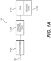
- Figures 1A-1C are a schematic view of a fluid heating system 1000 with a pressure regulating valve C-1000, and cross sectional views of the pressure regulating valve C-1000 in an open position and in a closed position, respectively and according to certain aspects of the disclosure.
- the fluid heating system 1000 can include a heating chamber A-1000 that receives fluid, e.g. water, from a supply line 100 and provides heated fluid via a dispensing device B-1000 with a drain B-1100, e.g. a faucet with a sink, that dispenses the heated fluid.
- the fluid heating system also includes a pressure regulating valve C-1000 that connects an outlet of the heating chamber A-1000 with an inlet of the drain B-1100 to facilitate draining of the heating chamber A-1000.
- the pressure regulating valve C-1000 is articulable between an open position and a closed position. In the open position the pressure regulating valve C-1000 provides a passage of the fluid from the heating chamber A-1000 to the drain B-1100 of the dispensing device B-1000. In the closed position, the pressure regulating valve C-1000 blocks the passage of the fluid if the fluid has a pressure below a predetermined pressure threshold and allows the passage of a predetermined amount of fluid if the fluid has a pressure above the predetermined pressure threshold.
- the predetermined pressure threshold can correspond to a maximum pressure up to which the heating chamber A-1000 can withstand before failures may occur, e.g. cracking, and/or overheating.
- the connection between the heating chamber A-1000 and the drain B-1100 via the pressure regulating valve C-1000 prevents pressure accumulations in the heating chamber A-1000 and evacuates the fluid directly through a dedicated and preexisting route, e.g. the drain B-1100, without causing fluid damages, e.g. fluid discharges, staining, mold growing, or the like.
- the pressure regulating valve C-1000 can include a valve body C-1100, a valve inlet C-1200 on one side of the valve body C-1100 that receives heated fluid from the heating chamber A-1000, a valve outlet C-1300 on an opposite side of the valve body C-1100 that outputs the heated fluid towards the drain B-1100, a valve handle C-1400 that protrudes from the valve body C-1100, and a ball valve C-1500 inside the valve body C-1100 connected to the valve handle C-1400 and articulable between the open position and the closed position via the valve handle C-1400.
- the pressure regulating valve C-1000 can include a seal C-1600 between the ball valve C-1500 and the valve body C-1100 to prevent fluid from leaking into the valve body C-1100 from the ball valve C-1500.
- the ball valve C-1500 can also include a ball through hole C-1510 that is aligned with the valve inlet C-1200 and the valve outlet C-1300 when the pressure regulating valve C-1000 is in the open position, and a pressure regulator C-1700 that is aligned with the valve inlet C-1200 and the valve outlet C-1300 when the pressure regulating valve C-1000 is in the closed position.
- the pressure regulator C-1700 is elaborated to block the passage of the heated fluid when the pressure of the hot fluid at the valve inlet C-1200 is below the predetermined pressure threshold and to allow the passage of all or a portion of the heated fluid at a particular flow rate when the pressure of the hot fluid at the valve inlet C-1200 is above the predetermined pressure threshold.
- the predetermined pressure threshold can be between 0.1 bar to 20.0 bar, preferably between 0.5 bar to 10.0 bar, and more preferably between 1.0 bar and 5.0 bar, which corresponds to pressure in residential heating system.
- the pressure regulator C-1700 can include a channel C-1710 aligned with the valve inlet C-1200 and the valve outlet C-1300 when the pressure regulating valve C-1000 is in the closed position, and substantially perpendicular with the valve inlet C-1200 and the valve outlet C-1300 when the pressure regulating valve C-1000 is in the open position.
- the channel C-1710 may include a regulator inlet with a seat C-1730, a regulator ball C-1740 to lodge in the seat C-1730, and bias mechanism C-1720, e.g. spring, to push the regulator ball C-1740 against the seat C-1730 and block the passage of the fluid when the pressure of the fluid at the valve inlet C-1200 is below the predetermined pressure threshold and to let the regulator ball C-1740 move away from the seat C-1730 when the pressure of the fluid at the valve inlet C-1200 is above the predetermined pressure threshold and let the fluid pass through the channel C-1710 and the pressure regulating valve C-1000.
- bias mechanism C-1720 e.g. spring
- the channel C-1710 is configured to prevent damages, e.g. pipe cracking, and bursting, projection of hot fluid and/or steam, from occurring by generating a narrow passage, e.g. passage smaller than a diameter of the ball valve C-1500, between the heating chamber A-1000 and the drain B-1100 when the pressure inside the heating chamber A-1000 is above the predetermined threshold even if the pressure regulating valve C-1000 is in the closed position.
- a narrow passage e.g. passage smaller than a diameter of the ball valve C-1500
- the elements of the pressure regulating valve C-1000 can be made of materials configured to resist to a minimum fluid pressure, e.g. pressure superior to the predetermined pressure threshold, as well as to facilitate the articulation of the pressure regulating valve C-1000 between the close position and the open position.
- the valve body C-1100 can be made of metal, plastic, or metal with a ceramic, for strength, while the ball valve C-1500 can be chrome plated for durability and to provide a smooth contact between the valve body C-1100 and the seal C-1600.
- Figures 2A-2B are a schematic view of the fluid heating system 1000 with an energy recovery device D-1000 and a cross sectional view of the energy recovery device D-1000, respectively, according to certain aspects of the disclosure.
- the fluid heating system 1000 can include an energy recovery device D-1000 to harvest energy provided by the flow of fluid from the heating chamber A-1000 to dispensing device B-1000.
- the energy recovery device D-1000 can include a turbine D-1100 driven by a flow of heated fluid when the dispensing device B-1000 dispenses the heated fluid, an electrical generator D-1200 driven by the turbine D-1100 that generates electrical energy, a regulator D-1300 that regulates the electrical energy and provides regulated energy, e.g. constant voltage and/or current, and batteries D-1400 that store the regulated energy and feed a thermostatic control device E-1000 that controls power supplied to the heating chamber A-1000.
- a turbine D-1100 driven by a flow of heated fluid when the dispensing device B-1000 dispenses the heated fluid
- an electrical generator D-1200 driven by the turbine D-1100 that generates electrical energy
- a regulator D-1300 that regulates the electrical energy and provides regulated energy, e.g. constant voltage and/or current
- batteries D-1400 that store the regulated energy and feed a thermostatic control device E-1000 that controls power supplied to the heating chamber A-1000.
- the elements of the energy recovery device D-1000 e.g. the turbine D-1100, the electrical generator D-1200, the regulator D-1300, and/or the batteries D-1400, are configured to be sufficiently small to fit below and/or inside the dispensing device B-1000.
- the recovery energy device D-1000 provides the ability to feed power to the thermostatic control device E-1000 without requiring an external power source, e.g. house hold electrical supply, or any electrical equipment necessary to transfer, convert, and/or transform the electrical energy provided by the external source into an electrical energy acceptable for the thermostatic control device E-1000, e.g. line transformers, and/or cables. Such electrical equipment may be voluminous and consume additional energy. Consequently, the energy recovery device D-1000 provides improvements of space and energy for the fluid heating device 1000.
- an external power source e.g. house hold electrical supply
- Such electrical equipment may be voluminous and consume additional energy. Consequently, the energy recovery device D-1000 provides improvements of space and energy for the fluid heating device 1000.
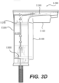
- Figures 3A-3B are a schematic and a cross sectional views of the fluid heating system 1000 with the thermostatic control device E-1000 integrated into the fluid dispensing device B-1000, respectively and according to certain aspects of the disclosure.
- the fluid heating system 1000 can include a thermostatic control device E-1000 that supplies power to the heating chamber A-1000 as the heated fluid is dispensed via the dispensing device B-1000 and maintains a supply of heated fluid at a preset temperature T.
- the thermostatic control device E-1000 can include a plurality of sensors, e.g. temperature sensors, pressures sensors, and/or flow sensors, to provide fluid signals commensurate with thermo-hydro-dynamic parameters, e.g. temperature, pressure, and/or flow rate, of the fluid.
- sensors e.g. temperature sensors, pressures sensors, and/or flow sensors, to provide fluid signals commensurate with thermo-hydro-dynamic parameters, e.g. temperature, pressure, and/or flow rate, of the fluid.
- the thermostatic control device E-1000 can include an inlet temperature sensor E-1200 placed upstream of the heating chamber A-1000 to provide readings indicative of an inlet temperature T in , a flow meter E-1400 placed upstream of the heating chamber A-1000 that provides readings indicative of a flow rate Q of the cold fluid going through the heating chamber A-1000, an outlet temperature sensor E-1300 placed downstream of the heating chamber A-1000 that provides readings indicative of an outlet temperature T out , a power switch E-1500, e.g.
- a TRIAC that controls the power supplied to the heating chamber A-1000
- an Electrical Control Unit (ECU) E-1100 that receives the readings provided by the inlet temperature sensor E-1200 and the flow meter E-1400, and controls the power switch E-1500, based on the inlet temperature T in and the flow rate Q, to dispense the heated fluid at the preset temperature T.
- ECU Electrical Control Unit
- the ECU E-1100 may control the power switch E-1500 via Pulse Width Modulation (PWM), Pulse Density Modulation (PDM), Phase Control, Proportional Integral Derivative (PID) techniques, other methods, algorithms, and/or software instructions to manage and supply adequate power to the heating chamber A-1000.
- PWM Pulse Width Modulation
- PDM Pulse Density Modulation
- PID Phase Control
- PID Proportional Integral Derivative
- the ECU E-1100 can be configured to actuate the power switch E-1500 to supply power to the heating chamber A-1000 when the flow rate Q is above a predetermined minimum flow rate threshold and to actuate the power switch E-1500 to not supply power to the heating chamber A-1000 when the flow rate Q is below the predetermined minimum flow rate threshold. Further, the ECU E-1100 can actuate the power switch E-1500 to increase the power supplied to the heating chamber A-1000 as the flow rate Q increases and to decrease the power supplied to the heating chamber A-1000 as the flow rate Q decreases.
- the ECU E-1100 can be configured to take into account the outlet temperature T out to manage more accurately the power supplied to the heating chamber A-1000.
- the ECU E-1100 can actuate the power switch E-1500 to control the power supplied to the heating chamber A-1000 through a feedback loop mechanism, e.g. a PID loop, between the inlet temperature T in and the outlet temperature T out .
- a feedback loop mechanism e.g. a PID loop
- the thermostatic control device E-1000 precisely and effectively adjusts the power supplied to the heating chamber A-1000 making the fluid heating system 1000 more efficient and capable to dispense hot fluid at a temperature matching the preset temperature T.
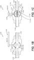
- Figures 3C-3D are cross sectional views of a mixing valve E-2000 and a manual mixing valve E-3000 integrated into the dispensing device B-1000, according to certain aspects of the disclosure.
- the fluid heating system 1000 can include a mixing valve E-2000 that controls the temperature of the heated fluid dispensed by the dispensing device B-1000.
- the mixing valve E-2000 can mix the heated fluid coming out from the heating chamber A-1000 with the cold fluid entering the heating chamber A-1000 and provide a tempered fluid temperature below a predetermined maximum temperature.
- the mixing valve E-2000 can prevent the tempered fluid from being dispensed at an excessive temperature, e.g. above the predetermined maximum temperature, which can be desired for public handwashing applications and to meet regulations and/or codes such as the ASSE 1070 code.
- the mixing valve E-2000 can include a cold supply line E-2200 that runs between an inlet of the heating chamber A-1000 and a cold inlet of the mixing valve E-2000 to partially diverge the cold fluid entering the heating chamber A-1000 and supplies the mixing valve E-2000 with the cold fluid.
- the mixing valve E-2000 can also include a hot supply line E-2100 that runs between an outlet of the heating chamber A-1000 and a hot inlet of the mixing valve E-2000 and supplies the mixing valve E-2000 with the hot fluid, and a dispense line E-2300 that runs between an outlet of the mixing valve E-2000 and an outlet of the dispensing device B-1000 and supplies the temperature controlled fluid.
- the mixing valve E-2000 can include a knob E-2400 that adjusts a mixing ratio between the hot fluid and the cold fluid and consequently adjust the predetermined maximum temperature of the tempered fluid.
- the knob E-2400 can be manually controlled or controlled via servo-mechanics based on control feedback and information analyzed by the ECU E-1000.
- the fluid heating system 1000 including the mixing valve E-2000 can be completely or partially integrated inside the fluid dispensing device B-1000 to gain space.
- the heating chamber A-1000 can be placed inside a body B-1200 of the fluid dispensing device B-1000, the mixing valve E-2000 can be positioned above the heating chamber A-1000 with the hot inlet of the mixing valve E-2000 directly connected to the outlet of the heating chamber A-1000 to minimize a length of the hot supply line E-2100.
- the cold supply line E-2200 can run along the heating chamber A-1000 and inside the body B-1200 of the fluid dispensing device B-1000 and the dispensing line E-2300 can run inside and along a beak B-1300 of the dispensing device B-1000.
- knob E-2400 of the mixing valve E-2000 can be placed on top of the mixing valve E-2000 and can face upwardly to be easily accessible by a user when manual adjustment of the mixing ratio is desired.
- a manual mixing valve E-3000 can be placed upstream of the inlet of the heating chamber A-1000 to provide additional controls in mixing the hot fluid with the cold fluid and dispensing the temperature controlled fluid, as illustrated in Fig. 3D .
- Figure 4 is a cross sectional view of the fluid heating system 1000 with a cold channeling system F-1000, according to certain aspects of the disclosure.
- the heating chamber A-1000 can include a cold channeling system F-1000 that insulates the user and/or other outside surfaces from heat generated by the heating chamber A-1000.
- the cold channeling system F-1000 can force the cold fluid entering the heating chamber A-1000 to follow a predetermined path before being heated by the heating chamber A-1000 so as to limit heat diffused through the body B-1200 of the dispensing device B-1000.
- the predetermined path can envelope an internal volume of the heating chamber A-1000 to form a jacket of cold fluid that limits heat diffusion through the heating chamber A-1000 towards the exterior of the dispensing device B-1000.
- the predetermined path can be similar to a Hill vortex that goes radially along a lower side A-1100 of the heating chamber A-1000, upwardly along walls A-1200 of the heating chamber A-1000 adjacent to the body B-1200 of the fluid dispensing device B-1000, radially along an upper side A-1300 of the heating chamber A-1000, and downwardly towards the lower side A-1100 of the heating chamber A-1000 to be heated by the heating chamber A-1000.
- a Hill vortex that goes radially along a lower side A-1100 of the heating chamber A-1000, upwardly along walls A-1200 of the heating chamber A-1000 adjacent to the body B-1200 of the fluid dispensing device B-1000, radially along an upper side A-1300 of the heating chamber A-1000, and downwardly towards the lower side A-1100 of the heating chamber A-1000 to be heated by the heating chamber A-1000.
- the cold channeling system F-1000 may rely on channels and/or diffusors A-8000, e.g. winglets, spoilers, and/or geometrical structures configured to deflect the cold fluid, placed on an internal surface of the heating chamber A-1000 that forces the cold fluid to follow the predetermined path and prevent the fluid heating system 1000 from using a separate medium to insulate the heating chamber A-1000. This provides additional advantages of reduced parts, repair and production costs.
- channels and/or diffusors A-8000 e.g. winglets, spoilers, and/or geometrical structures configured to deflect the cold fluid, placed on an internal surface of the heating chamber A-1000 that forces the cold fluid to follow the predetermined path and prevent the fluid heating system 1000 from using a separate medium to insulate the heating chamber A-1000.
- the heating chamber A-1000 can be similar to or include a heating device A-9000 disclosed in the U.S. Patent No. 9,234,674 , which is herein incorporated by reference in its entirety.
- the heating chamber A-1000 may heat fluid passing therein by other methods as would be understood by one of ordinary skill in the art.
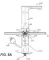
- Figures 5A , 5B, 5C are cross sectional views of a supplemental heating chamber A-2000 connected to the fluid dispensing device B-1000, a passage A-2100 of the supplemental heating chamber A-2000, and a stem A-2200 of the supplemental heating chamber A-2000 affixed to the dispensing device B-1000, respectively and according to certain aspects of the disclosure.
- the fluid heating system 1000 can include a supplemental heating chamber A-2000 configured to be affixed below a support surface 500 of the dispensing device B-1000, e.g. a counter top or a sink basin, to facilitate an installation of the fluid heating system 1000 by providing ease of access, visibility and by limiting the use of tools.
- a supplemental heating chamber A-2000 configured to be affixed below a support surface 500 of the dispensing device B-1000, e.g. a counter top or a sink basin, to facilitate an installation of the fluid heating system 1000 by providing ease of access, visibility and by limiting the use of tools.
- the supplemental heating chamber A-2000 can include a passage A-2100 that goes through a full length of the supplemental heating chamber A-2000, a stem A-2200, a cold inlet A-2300 that receives the cold fluid, a hot outlet A-2400 that dispenses heated fluid, and a cold outlet A-2500 that dispenses the cold fluid back from the heating chamber A-1000 and/or a supplementary fluid line.
- the supplemental heating chamber A-2000 can also include a connection system A-2600 that connects the hot outlet A-2400 and the cold outlet A-2500 to a hot inlet A-2410 of the fluid dispensing device B-1000 and a cold inlet A-2510 of the fluid dispensing device B-1000, respectively.
- an electrical supply line A-2700 is provided to feed the supplemental heating chamber A-2000 with electrical energy for heating fluid.
- the stem A-2200 can include a stem first end A-2210 that protrudes from an upper side A-2110 of the supplemental heating chamber A-2000 and a stem second end A-2220 that protrudes from a lower side A-2120 of the supplemental heating chamber A-2000, wherein the stem first end A-2210 is affixed to the dispensing device B-1000, e.g. through threading, and a fastening device A-2230, e.g. a jamb nut, is inserted through the stem second end A-2220 to press the supplemental heating chamber A-2000 against the support surface 500, and connect the fluid dispensing device B-1000, via the connection system A-2600.
- a fastening device A-2230 e.g. a jamb nut
- connection system A-2600 can easily, e.g. without tool and through a plug-in/out action, connect the hot outlet A-2400 and the cold outlet A-2500 of the supplemental heating chamber A-2000 to a cold inlet and a hot inlet of the dispensing device B-1000, as well as disconnect the hot outlet A-2400 and the cold outlet A-2500 of the supplemental heating chamber A-2000 from the cold inlet and the hot inlet of the dispensing device B-1000.
- connection system A-2600 can rely on quick connect fittings to make- or-break connections between the supplemental heating chamber A-2000 and the dispensing device B-1000.
- the quick connect fittings can rely on a male tubing and matching female tubing with fastening teeth that lock the male tubing inside the female tubing when a connecting force is applied between the male tubing and the female tubing and wherein the fastening teeth unlock and release the male tubing from the female tubing when an disconnecting force is applied between the male tubing and the female tubing.
- the passage A-2100 can have an internal profile passage A-2110 that matches an external profile stem of the stem A-2200, as illustrated in Fig. 5B , to assure alignment between the cold outlet A-2500 of the supplemental heating chamber A-2000 and the cold inlet A-2510 of the dispensing device B-1000 as well as to assure alignment between the hot outlet A-2400 of the supplemental heating chamber A-2000 and the hot inlet A-2410 of the dispensing device B-1000.
- the internal profile passage A-2110 and the external profile stem can have a partial circular shape with a flat portion A-2112 to prevent rotation of the supplemental heating chamber A-2000 around the stem A-2200, as illustrated in Fig. 5B .
- the supplemental heating chamber A-2000 can be used in combination with the heating chamber A-1000, as illustrated in Fig. 5A , to enhance the ability to heat the cold fluid.
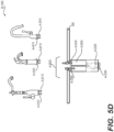
- Figures 5D-5E are sectional views of the supplemental heating chamber A-2000 connected to the dispensing device B-1000, and mounted onto a standard supply line 600, respectively and according to certain aspects of the disclosure.
- the supplemental heating chamber A-2000 can be used alone and mounted directly to the dispensing device B-1000 equipped with the hot inlet A-2410 and the cold inlet A-2510 to receive the hot outlet A-2400 and cold outlet A-2500 of the supplemental heating chamber A-2000, as illustrated in Fig. 5D .
- Fig. 5E shows an alternative not forming part of the invention
- the supplemental heating chamber A-2000 can include a standard hot outlet 800 elaborated to be used with standard compression hoses, e.g. 3/8", of the standard supply line 600.
Landscapes
- Engineering & Computer Science (AREA)
- Food Science & Technology (AREA)
- Mechanical Engineering (AREA)
- Health & Medical Sciences (AREA)
- Life Sciences & Earth Sciences (AREA)
- Hydrology & Water Resources (AREA)
- Public Health (AREA)
- Water Supply & Treatment (AREA)
- Physics & Mathematics (AREA)
- Thermal Sciences (AREA)
- Chemical & Material Sciences (AREA)
- Combustion & Propulsion (AREA)
- General Engineering & Computer Science (AREA)
- Details Of Valves (AREA)
- Apparatus For Disinfection Or Sterilisation (AREA)
- Steam Or Hot-Water Central Heating Systems (AREA)
- Physical Or Chemical Processes And Apparatus (AREA)
- Central Heating Systems (AREA)
- Catching Or Destruction (AREA)
Claims (15)
- Fluiderwärmungssystem, umfassend:eine Heizkammer (A-1000), die Fluid aufnimmt und erwärmt, um erwärmtes Fluid bereitzustellen;eine Ausgabevorrichtung (B-1000), die das erwärmte Fluid ausgibt, wobei die Ausgabevorrichtung (B-1000) die Heizkammer (A-1000) umgibt;eine thermostatische Steuervorrichtung (E-1000), die eine Stromversorgung der Heizkammer (A-1000) regelt;einen Abfluss (B-1100), der zu einer äußeren Umgebung hin offen ist, undein Druckregelventil (C-1000), das zwischen einer geöffneten Stellung und einer geschlossenen Stellung schwenkbar ist, wobeiin der geöffneten Stellung der Durchgang für das erwärmte Fluid zwischen dem Abfluss (B-1100) und der Heizkammer (A-1000) gegeben ist undin der geschlossenen Stellung der Durchgang für das erwärmte Fluid zwischen der Heizkammer (A-1000) und dem Abfluss (B-1100) verhindert wird, wenn ein Druck in der Heizkammer (A-1000) unter einer vorbestimmten Druckschwelle liegt;dadurch gekennzeichnet, dassbei in der geschlossenen Stellung befindlichem Druckregelventil der Durchgang für das erwärmte Fluid zwischen der Heizkammer (A-1000) und dem Abfluss (B-1100) gegeben ist, wenn der Druck in der Heizkammer (A-1000) über der vorbestimmten Druckschwelle liegt; unddas Fluiderwärmungssystem ferner eine Energierückgewinnungsvorrichtung (D-1000) umfasst, die mechanische Energie erntet, die durch einen Durchfluss des erwärmten Fluids von der Heizkammer (A-1000) zur Ausgabevorrichtung (B-1000) bereitgestellt wird, und elektrische Energie zum Betreiben der thermostatischen Steuervorrichtung (E-1000) erzeugt.
- Fluiderwärmungssystem nach Anspruch 1, wobei das Druckregelventil (C-1000) beinhaltet:einen Ventilkörper (C-1100),einen Ventileinlass (C-1200), der erwärmtes Fluid aus der Heizkammer (A-1000) erhält,einen Ventilauslass (C-1300), der das erwärmte Fluid zum Abfluss hin ausgibt, undein Kugelventil (C-1500), das zwischen der offenen Stellung und der geschlossenen Stellung schwenkbar ist.
- Fluiderwärmungssystem nach Anspruch 2, wobei die Ventilkugel beinhaltet:ein Kugeldurchgangsloch (C-1510), das auf den Ventileinlass (C-1200) und den Ventilauslass (C-1300) ausgerichtet ist, wenn das Druckregelventil (C-1000) in der geöffneten Stellung ist, undeinen Druckregler (C-1700), der auf den Ventileinlass (C-1200) und den Ventilauslass (C-1300) ausgerichtet ist, wenn das Druckregelventil (C-1000) in der geschlossenen Stellung ist.
- Fluiderwärmungssystem nach Anspruch 3, wobei der Druckregler (C-1700) beinhaltet:einen Reglereinlass mit einem Sitz (C-1730),eine Reglerkugel (C-1740) zum Lagern in dem Sitz (C-1730) undeine Feder (C-1720) zumDrücken der Reglerkugel (C-1740) gegen den Sitz (C-1730) und zum Verhindern des Durchgangs des Fluids, wenn der Druck des Fluids am Ventileinlass (C-1200) unter der vorbestimmten Druckschwelle ist, undErgeben von Bewegung der Reglerkugel (C-1740) von dem Sitz (C-1730) weg, wenn der Druck des Fluids am Ventileinlass (C-1200) über der vorbestimmten Druckschwelle ist.
- Fluiderwärmungssystem nach Anspruch 1, ferner umfassend:
eine Zusatzheizkammer (A-2000), die über ein Verbindungssystem mit der Heizkammer (A-1000) verbunden ist. - Fluiderwärmungssystem nach Anspruch 5, wobei die Zusatzheizkammer (A-2000) eine Vielzahl von Kanälen enthält, die einen Strömungsweg von kaltem Fluid um eine Innenfläche der Zusatzheizkammer (A-2000) bereitstellen.
- Fluiderwärmungssystem nach Anspruch 1, ferner umfassend:
ein Mischventil (E-2000), das zum Steuern des Mischens zwischen dem erwärmten Fluid und dem kalten Fluid zwischen der Heizkammer (A-1000) und der Ausgabevorrichtung (B-1000) positioniert ist. - Fluiderwärmungssystem nach Anspruch 7, wobei das Mischventil (E-2000) einen Kalteinlass beinhaltet, der Fluid aus einem Kanal erhält, der an einer Außenfläche der Heizkammer (A-1000) entlang verläuft.
- Fluiderwärmungssystem nach Anspruch 1, wobei:
die thermostatische Steuervorrichtung (E-1000) beinhaltet:eine Vielzahl von Sensoren zum Bereitstellen von Messungen, die für thermo-hydrodynamische Parameter des kalten Fluids und des erwärmten Fluids bezeichnend sind,einen Leistungsschalter (E-1500) zum Empfangen von Betätigungssignalen, die für einen Wärmebedarf bezeichnend sind, undeine elektrische Steuereinheit (E-1200), die konfiguriert ist zumEmpfangen der Messungen undBereitstellen der Betätigungssignale auf Basis der Messungen. - Fluiderwärmungssystem nach Anspruch 9, wobei die Vielzahl von Sensoren einen ersten Temperatursensor (E-1200) beinhaltet, der der Heizkammer (A-1000) vorgeschaltet ist, um Signale bereitzustellen, die für eine Einlasstemperatur des kalten Fluids bezeichnend sind.
- Fluiderwärmungssystem nach Anspruch 9, wobei die Vielzahl von Sensoren einen zweiten Temperatursensor (E-1300) beinhaltet, der der Heizkammer (A-1000) nachgeschaltet positioniert ist, um Signale bereitzustellen, die für eine Auslasstemperatur des erwärmten Fluids bezeichnend sind.
- Fluiderwärmungssystem nach Anspruch 9, wobei die Vielzahl von Sensoren einen Durchflussmesser (E-1400) beinhaltet, der der Heizkammer (A-1000) vorgeschaltet angeordnet ist, um Signale bereitzustellen, die für einen Durchfluss des kalten Fluids bezeichnend sind.
- Fluiderwärmungssystem nach Anspruch 1, ferner umfassend:
ein Mischventil (E-2000), das das erwärmte Fluid aus der Heizkammer (A-1000) mit dem in die Heizkammer (A-1000) eintretenden kalten Fluid mischt, um erwärmtes Fluid mit einer Temperatur unter einer vorbestimmten Höchsttemperatur bereitzustellen. - Fluiderwärmungssystem nach Anspruch 1, wobei die Heizkammer (A-1000) ferner an einer Innenfläche der Heizkammer (A-1000) positionierte Kanäle beinhaltet, die das kalte Fluid zwingen, einem vorbestimmten Pfad zu folgen, um ferner das Fluiderwärmungssystem thermisch zu isolieren.
- Fluiderwärmungssystem nach Anspruch 14, wobei der vorbestimmte Pfad einem Hillschen Wirbel entspricht.
Applications Claiming Priority (2)
| Application Number | Priority Date | Filing Date | Title |
|---|---|---|---|
| US201762452023P | 2017-01-30 | 2017-01-30 | |
| PCT/US2018/015961 WO2018140947A1 (en) | 2017-01-30 | 2018-01-30 | Fluid heating system |
Publications (4)
| Publication Number | Publication Date |
|---|---|
| EP3574153A1 EP3574153A1 (de) | 2019-12-04 |
| EP3574153A4 EP3574153A4 (de) | 2020-12-09 |
| EP3574153B1 true EP3574153B1 (de) | 2025-01-01 |
| EP3574153C0 EP3574153C0 (de) | 2025-01-01 |
Family
ID=62977183
Family Applications (1)
| Application Number | Title | Priority Date | Filing Date |
|---|---|---|---|
| EP18744924.4A Active EP3574153B1 (de) | 2017-01-30 | 2018-01-30 | Flüssigkeitserwärmungssystem |
Country Status (7)
| Country | Link |
|---|---|
| US (1) | US10183853B2 (de) |
| EP (1) | EP3574153B1 (de) |
| CN (1) | CN110366623B (de) |
| AU (2) | AU2018212003B2 (de) |
| CA (1) | CA3052075A1 (de) |
| MX (1) | MX2019009054A (de) |
| WO (1) | WO2018140947A1 (de) |
Families Citing this family (6)
| Publication number | Priority date | Publication date | Assignee | Title |
|---|---|---|---|---|
| KR102655478B1 (ko) | 2018-07-13 | 2024-04-08 | 엘지전자 주식회사 | 온수 공급 장치 및 그 제어 방법 |
| KR20200007363A (ko) * | 2018-07-13 | 2020-01-22 | 엘지전자 주식회사 | 온수 공급 장치 및 그 제어 방법 |
| IT202000005437A1 (it) * | 2020-03-13 | 2021-09-13 | Unival Srl | Cartuccia riscaldante per un gruppo erogatore e gruppo erogatore comprendente detta cartuccia riscaldante |
| US11984768B2 (en) | 2020-04-17 | 2024-05-14 | Zurn Water, Llc | Hydroelectric generator for faucet and flush valve |
| TWI722910B (zh) * | 2020-05-26 | 2021-03-21 | 東陞國際科技股份有限公司 | 流速控制方法及其沖泡機台 |
| GB2623302B (en) * | 2022-10-07 | 2025-04-02 | Otter Controls Ltd | Heated liquid dispenser |
Family Cites Families (26)
| Publication number | Priority date | Publication date | Assignee | Title |
|---|---|---|---|---|
| US1118320A (en) * | 1914-11-24 | Henry Gruenhagen | Electric water-heating faucet. | |
| US1847198A (en) * | 1930-09-06 | 1932-03-01 | Samuel S Torrisi | Detachable hot water unit for faucets |
| IL80806A0 (en) * | 1986-11-28 | 1987-02-27 | Avraham Kochal | Faucet mixing battery |
| CN2034252U (zh) * | 1988-07-11 | 1989-03-15 | 黎冬华 | 全自动冷热自来水机 |
| IT1254821B (it) * | 1992-02-28 | 1995-10-11 | Mario Giacomini | Valvola a sfera |
| CN2432499Y (zh) * | 2000-04-18 | 2001-05-30 | 刘改成 | 煤热电热两用暖气热水器 |
| ES2496540T3 (es) * | 2003-03-18 | 2014-09-19 | Pipers Operations Limited | Calentador de fluidos |
| CN2735238Y (zh) * | 2004-08-13 | 2005-10-19 | 谢庆俊 | 电热水器恒温衡压控制器 |
| GB0607040D0 (en) * | 2006-04-07 | 2006-05-17 | Dlp Ltd | Improvements in and relating to electric showers |
| WO2009013882A1 (ja) * | 2007-07-23 | 2009-01-29 | Toto Ltd. | 水栓用発電機 |
| DE102007050519A1 (de) | 2007-10-19 | 2009-04-23 | Stiebel Eltron Gmbh & Co. Kg | Heizarmatur und Verfahren zum Betrieb einer Heizarmatur |
| CN100494750C (zh) | 2007-12-03 | 2009-06-03 | 王存 | 温控压差回水龙头 |
| US8294292B2 (en) * | 2009-04-22 | 2012-10-23 | Rain Bird Corporation | Power supply system |
| US20100308591A1 (en) * | 2009-06-09 | 2010-12-09 | Godfrey Carl L | Inline hydro electric generation system |
| JP5836277B2 (ja) * | 2009-09-25 | 2015-12-24 | ヘンリ ペテリ ベヘール ベー.フェー. | 熱水又は沸騰水を定量排出する装置 |
| IT1398395B1 (it) * | 2009-10-05 | 2013-02-22 | Giuliani | Rubinetto riscaldatore |
| CN101825189A (zh) * | 2010-05-28 | 2010-09-08 | 周剑冰 | 一种电子恒温水龙头装置 |
| US8840041B2 (en) * | 2010-10-12 | 2014-09-23 | Drakken Industries, Llc | Shower head having an electric tankless water heater |
| US9140466B2 (en) * | 2012-07-17 | 2015-09-22 | Eemax, Inc. | Fluid heating system and instant fluid heating device |
| US10222091B2 (en) * | 2012-07-17 | 2019-03-05 | Eemax, Inc. | Next generation modular heating system |
| AU2013302327B2 (en) * | 2012-08-17 | 2017-06-29 | Power4U Energy Pty Ltd | Inline power generator |
| US20180038229A1 (en) * | 2012-08-17 | 2018-02-08 | Spinergy Pty Ltd | Inline power generator |
| US9863396B2 (en) * | 2014-06-16 | 2018-01-09 | Gary Joseph Oncale | Systems and methods for generating energy |
| US20160015178A1 (en) * | 2014-07-21 | 2016-01-21 | Mohammed Abdullah ALSHADY | Spray for kitchens and restrooms |
| MX384645B (es) * | 2014-12-17 | 2025-03-14 | Rheem Mfg Co | Calentador de agua eléctrico sin tanque. |
| US20160322886A1 (en) * | 2015-04-30 | 2016-11-03 | Joseph Brienze, JR. | Water Generator System |
-
2018
- 2018-01-30 CN CN201880014440.9A patent/CN110366623B/zh active Active
- 2018-01-30 EP EP18744924.4A patent/EP3574153B1/de active Active
- 2018-01-30 US US15/884,061 patent/US10183853B2/en active Active
- 2018-01-30 CA CA3052075A patent/CA3052075A1/en active Pending
- 2018-01-30 MX MX2019009054A patent/MX2019009054A/es unknown
- 2018-01-30 AU AU2018212003A patent/AU2018212003B2/en not_active Ceased
- 2018-01-30 WO PCT/US2018/015961 patent/WO2018140947A1/en not_active Ceased
-
2021
- 2021-05-25 AU AU2021203392A patent/AU2021203392A1/en not_active Abandoned
Also Published As
| Publication number | Publication date |
|---|---|
| CA3052075A1 (en) | 2018-08-02 |
| AU2021203392A1 (en) | 2021-06-24 |
| MX2019009054A (es) | 2020-02-05 |
| AU2018212003A1 (en) | 2019-08-22 |
| CN110366623B (zh) | 2022-05-17 |
| EP3574153A4 (de) | 2020-12-09 |
| EP3574153C0 (de) | 2025-01-01 |
| US20180215602A1 (en) | 2018-08-02 |
| WO2018140947A1 (en) | 2018-08-02 |
| US10183853B2 (en) | 2019-01-22 |
| CN110366623A (zh) | 2019-10-22 |
| EP3574153A1 (de) | 2019-12-04 |
| AU2018212003B2 (en) | 2021-02-25 |
Similar Documents
| Publication | Publication Date | Title |
|---|---|---|
| EP3574153B1 (de) | Flüssigkeitserwärmungssystem | |
| US7198059B2 (en) | Apparatus and system for retrofitting water control valves | |
| US8522814B2 (en) | Water control valve assembly | |
| US10087607B2 (en) | Shower head with integrated mixing valve | |
| CN101280852B (zh) | 智能恒温阀 | |
| JP5548449B2 (ja) | 可変温度の水を供給する装置 | |
| KR101755243B1 (ko) | 스마트한 온수제공시스템 | |
| JP2020522668A (ja) | 再循環流体加熱システム | |
| CN101576285B (zh) | 智能供水中央处理器 | |
| EP2239514A1 (de) | Wassersparsystem bei der Anforderung von heißem Wasser | |
| US20240318865A1 (en) | Combined water heater and thermostatic control | |
| US10907860B2 (en) | Electric tankless water heater | |
| CN220287733U (zh) | 一种即开即热恒温供水系统 | |
| KR102312524B1 (ko) | 절수형 온수 순환시스템 | |
| WO2010082162A2 (en) | Water heater | |
| MX2009012498A (es) | Valvula mezcladora de agua caliente y fria. |
Legal Events
| Date | Code | Title | Description |
|---|---|---|---|
| STAA | Information on the status of an ep patent application or granted ep patent |
Free format text: STATUS: THE INTERNATIONAL PUBLICATION HAS BEEN MADE |
|
| PUAI | Public reference made under article 153(3) epc to a published international application that has entered the european phase |
Free format text: ORIGINAL CODE: 0009012 |
|
| STAA | Information on the status of an ep patent application or granted ep patent |
Free format text: STATUS: REQUEST FOR EXAMINATION WAS MADE |
|
| 17P | Request for examination filed |
Effective date: 20190830 |
|
| AK | Designated contracting states |
Kind code of ref document: A1 Designated state(s): AL AT BE BG CH CY CZ DE DK EE ES FI FR GB GR HR HU IE IS IT LI LT LU LV MC MK MT NL NO PL PT RO RS SE SI SK SM TR |
|
| AX | Request for extension of the european patent |
Extension state: BA ME |
|
| DAV | Request for validation of the european patent (deleted) | ||
| DAX | Request for extension of the european patent (deleted) | ||
| A4 | Supplementary search report drawn up and despatched |
Effective date: 20201110 |
|
| RIC1 | Information provided on ipc code assigned before grant |
Ipc: E03C 1/044 20060101AFI20201104BHEP |
|
| REG | Reference to a national code |
Ref country code: DE Ref legal event code: R079 Free format text: PREVIOUS MAIN CLASS: E03C0001044000 Ipc: A47J0031460000 Ref country code: DE Ref legal event code: R079 Ref document number: 602018078112 Country of ref document: DE Free format text: PREVIOUS MAIN CLASS: E03C0001044000 Ipc: A47J0031460000 |
|
| STAA | Information on the status of an ep patent application or granted ep patent |
Free format text: STATUS: EXAMINATION IS IN PROGRESS |
|
| RIC1 | Information provided on ipc code assigned before grant |
Ipc: F24H 1/12 20060101ALI20230421BHEP Ipc: F24D 17/00 20060101ALI20230421BHEP Ipc: F24H 1/10 20060101ALI20230421BHEP Ipc: E03C 1/04 20060101ALI20230421BHEP Ipc: A47J 31/46 20060101AFI20230421BHEP |
|
| 17Q | First examination report despatched |
Effective date: 20230504 |
|
| GRAP | Despatch of communication of intention to grant a patent |
Free format text: ORIGINAL CODE: EPIDOSNIGR1 |
|
| STAA | Information on the status of an ep patent application or granted ep patent |
Free format text: STATUS: GRANT OF PATENT IS INTENDED |
|
| INTG | Intention to grant announced |
Effective date: 20240726 |
|
| RIN1 | Information on inventor provided before grant (corrected) |
Inventor name: MIHU, SERGIU, GABRIEL Inventor name: HAYDEN, CHRISTOPHER, MARK Inventor name: JURCZYSZAK, ERIC, ROBERT |
|
| GRAS | Grant fee paid |
Free format text: ORIGINAL CODE: EPIDOSNIGR3 |
|
| GRAA | (expected) grant |
Free format text: ORIGINAL CODE: 0009210 |
|
| STAA | Information on the status of an ep patent application or granted ep patent |
Free format text: STATUS: THE PATENT HAS BEEN GRANTED |
|
| AK | Designated contracting states |
Kind code of ref document: B1 Designated state(s): AL AT BE BG CH CY CZ DE DK EE ES FI FR GB GR HR HU IE IS IT LI LT LU LV MC MK MT NL NO PL PT RO RS SE SI SK SM TR |
|
| REG | Reference to a national code |
Ref country code: GB Ref legal event code: FG4D |
|
| REG | Reference to a national code |
Ref country code: CH Ref legal event code: EP |
|
| REG | Reference to a national code |
Ref country code: DE Ref legal event code: R096 Ref document number: 602018078112 Country of ref document: DE |
|
| REG | Reference to a national code |
Ref country code: IE Ref legal event code: FG4D |
|
| U01 | Request for unitary effect filed |
Effective date: 20250127 |
|
| U07 | Unitary effect registered |
Designated state(s): AT BE BG DE DK EE FI FR IT LT LU LV MT NL PT RO SE SI Effective date: 20250203 |
|
| PG25 | Lapsed in a contracting state [announced via postgrant information from national office to epo] |
Ref country code: PL Free format text: LAPSE BECAUSE OF FAILURE TO SUBMIT A TRANSLATION OF THE DESCRIPTION OR TO PAY THE FEE WITHIN THE PRESCRIBED TIME-LIMIT Effective date: 20250101 |
|
| PG25 | Lapsed in a contracting state [announced via postgrant information from national office to epo] |
Ref country code: ES Free format text: LAPSE BECAUSE OF FAILURE TO SUBMIT A TRANSLATION OF THE DESCRIPTION OR TO PAY THE FEE WITHIN THE PRESCRIBED TIME-LIMIT Effective date: 20250101 |
|
| PG25 | Lapsed in a contracting state [announced via postgrant information from national office to epo] |
Ref country code: NO Free format text: LAPSE BECAUSE OF FAILURE TO SUBMIT A TRANSLATION OF THE DESCRIPTION OR TO PAY THE FEE WITHIN THE PRESCRIBED TIME-LIMIT Effective date: 20250401 Ref country code: IS Free format text: LAPSE BECAUSE OF FAILURE TO SUBMIT A TRANSLATION OF THE DESCRIPTION OR TO PAY THE FEE WITHIN THE PRESCRIBED TIME-LIMIT Effective date: 20250501 |
|
| PG25 | Lapsed in a contracting state [announced via postgrant information from national office to epo] |
Ref country code: HR Free format text: LAPSE BECAUSE OF FAILURE TO SUBMIT A TRANSLATION OF THE DESCRIPTION OR TO PAY THE FEE WITHIN THE PRESCRIBED TIME-LIMIT Effective date: 20250101 |
|
| PG25 | Lapsed in a contracting state [announced via postgrant information from national office to epo] |
Ref country code: GR Free format text: LAPSE BECAUSE OF FAILURE TO SUBMIT A TRANSLATION OF THE DESCRIPTION OR TO PAY THE FEE WITHIN THE PRESCRIBED TIME-LIMIT Effective date: 20250402 |
|
| PG25 | Lapsed in a contracting state [announced via postgrant information from national office to epo] |
Ref country code: CZ Free format text: LAPSE BECAUSE OF FAILURE TO SUBMIT A TRANSLATION OF THE DESCRIPTION OR TO PAY THE FEE WITHIN THE PRESCRIBED TIME-LIMIT Effective date: 20250101 |
|
| U21 | Renewal fee for the european patent with unitary effect paid with additional fee |
Year of fee payment: 8 Effective date: 20250624 |
|
| REG | Reference to a national code |
Ref country code: CH Ref legal event code: PL |
|
| PG25 | Lapsed in a contracting state [announced via postgrant information from national office to epo] |
Ref country code: SM Free format text: LAPSE BECAUSE OF FAILURE TO SUBMIT A TRANSLATION OF THE DESCRIPTION OR TO PAY THE FEE WITHIN THE PRESCRIBED TIME-LIMIT Effective date: 20250101 |
|
| PG25 | Lapsed in a contracting state [announced via postgrant information from national office to epo] |
Ref country code: MC Free format text: LAPSE BECAUSE OF FAILURE TO SUBMIT A TRANSLATION OF THE DESCRIPTION OR TO PAY THE FEE WITHIN THE PRESCRIBED TIME-LIMIT Effective date: 20250101 |
|
| PG25 | Lapsed in a contracting state [announced via postgrant information from national office to epo] |
Ref country code: CH Free format text: LAPSE BECAUSE OF NON-PAYMENT OF DUE FEES Effective date: 20250131 |
|
| PG25 | Lapsed in a contracting state [announced via postgrant information from national office to epo] |
Ref country code: SK Free format text: LAPSE BECAUSE OF FAILURE TO SUBMIT A TRANSLATION OF THE DESCRIPTION OR TO PAY THE FEE WITHIN THE PRESCRIBED TIME-LIMIT Effective date: 20250101 |
|
| PLBE | No opposition filed within time limit |
Free format text: ORIGINAL CODE: 0009261 |
|
| STAA | Information on the status of an ep patent application or granted ep patent |
Free format text: STATUS: NO OPPOSITION FILED WITHIN TIME LIMIT |