EP3573192B1 - Kamera - Google Patents
Kamera Download PDFInfo
- Publication number
- EP3573192B1 EP3573192B1 EP18741292.9A EP18741292A EP3573192B1 EP 3573192 B1 EP3573192 B1 EP 3573192B1 EP 18741292 A EP18741292 A EP 18741292A EP 3573192 B1 EP3573192 B1 EP 3573192B1
- Authority
- EP
- European Patent Office
- Prior art keywords
- wire
- seal
- connector
- camera
- conductive wire
- Prior art date
- Legal status (The legal status is an assumption and is not a legal conclusion. Google has not performed a legal analysis and makes no representation as to the accuracy of the status listed.)
- Active
Links
Images


Classifications
-
- H—ELECTRICITY
- H01—ELECTRIC ELEMENTS
- H01R—ELECTRICALLY-CONDUCTIVE CONNECTIONS; STRUCTURAL ASSOCIATIONS OF A PLURALITY OF MUTUALLY-INSULATED ELECTRICAL CONNECTING ELEMENTS; COUPLING DEVICES; CURRENT COLLECTORS
- H01R13/00—Details of coupling devices of the kinds covered by groups H01R12/70 or H01R24/00 - H01R33/00
- H01R13/46—Bases; Cases
- H01R13/52—Dustproof, splashproof, drip-proof, waterproof, or flameproof cases
- H01R13/5216—Dustproof, splashproof, drip-proof, waterproof, or flameproof cases characterised by the sealing material, e.g. gels or resins
-
- H—ELECTRICITY
- H01—ELECTRIC ELEMENTS
- H01R—ELECTRICALLY-CONDUCTIVE CONNECTIONS; STRUCTURAL ASSOCIATIONS OF A PLURALITY OF MUTUALLY-INSULATED ELECTRICAL CONNECTING ELEMENTS; COUPLING DEVICES; CURRENT COLLECTORS
- H01R13/00—Details of coupling devices of the kinds covered by groups H01R12/70 or H01R24/00 - H01R33/00
- H01R13/46—Bases; Cases
- H01R13/52—Dustproof, splashproof, drip-proof, waterproof, or flameproof cases
- H01R13/5205—Sealing means between cable and housing, e.g. grommet
- H01R13/5208—Sealing means between cable and housing, e.g. grommet having at least two cable receiving openings
-
- H—ELECTRICITY
- H01—ELECTRIC ELEMENTS
- H01R—ELECTRICALLY-CONDUCTIVE CONNECTIONS; STRUCTURAL ASSOCIATIONS OF A PLURALITY OF MUTUALLY-INSULATED ELECTRICAL CONNECTING ELEMENTS; COUPLING DEVICES; CURRENT COLLECTORS
- H01R12/00—Structural associations of a plurality of mutually-insulated electrical connecting elements, specially adapted for printed circuits, e.g. printed circuit boards [PCB], flat or ribbon cables, or like generally planar structures, e.g. terminal strips, terminal blocks; Coupling devices specially adapted for printed circuits, flat or ribbon cables, or like generally planar structures; Terminals specially adapted for contact with, or insertion into, printed circuits, flat or ribbon cables, or like generally planar structures
- H01R12/50—Fixed connections
- H01R12/51—Fixed connections for rigid printed circuits or like structures
- H01R12/53—Fixed connections for rigid printed circuits or like structures connecting to cables except for flat or ribbon cables
-
- H—ELECTRICITY
- H01—ELECTRIC ELEMENTS
- H01R—ELECTRICALLY-CONDUCTIVE CONNECTIONS; STRUCTURAL ASSOCIATIONS OF A PLURALITY OF MUTUALLY-INSULATED ELECTRICAL CONNECTING ELEMENTS; COUPLING DEVICES; CURRENT COLLECTORS
- H01R13/00—Details of coupling devices of the kinds covered by groups H01R12/70 or H01R24/00 - H01R33/00
- H01R13/46—Bases; Cases
- H01R13/52—Dustproof, splashproof, drip-proof, waterproof, or flameproof cases
- H01R13/5213—Covers
-
- H—ELECTRICITY
- H01—ELECTRIC ELEMENTS
- H01R—ELECTRICALLY-CONDUCTIVE CONNECTIONS; STRUCTURAL ASSOCIATIONS OF A PLURALITY OF MUTUALLY-INSULATED ELECTRICAL CONNECTING ELEMENTS; COUPLING DEVICES; CURRENT COLLECTORS
- H01R4/00—Electrically-conductive connections between two or more conductive members in direct contact, i.e. touching one another; Means for effecting or maintaining such contact; Electrically-conductive connections having two or more spaced connecting locations for conductors and using contact members penetrating insulation
- H01R4/70—Insulation of connections
-
- H—ELECTRICITY
- H02—GENERATION; CONVERSION OR DISTRIBUTION OF ELECTRIC POWER
- H02G—INSTALLATION OF ELECTRIC CABLES OR LINES, OR OF COMBINED OPTICAL AND ELECTRIC CABLES OR LINES
- H02G15/00—Cable fittings
- H02G15/013—Sealing means for cable inlets
-
- G—PHYSICS
- G03—PHOTOGRAPHY; CINEMATOGRAPHY; ANALOGOUS TECHNIQUES USING WAVES OTHER THAN OPTICAL WAVES; ELECTROGRAPHY; HOLOGRAPHY
- G03B—APPARATUS OR ARRANGEMENTS FOR TAKING PHOTOGRAPHS OR FOR PROJECTING OR VIEWING THEM; APPARATUS OR ARRANGEMENTS EMPLOYING ANALOGOUS TECHNIQUES USING WAVES OTHER THAN OPTICAL WAVES; ACCESSORIES THEREFOR
- G03B17/00—Details of cameras or camera bodies; Accessories therefor
- G03B17/02—Bodies
- G03B17/08—Waterproof bodies or housings
-
- H—ELECTRICITY
- H01—ELECTRIC ELEMENTS
- H01R—ELECTRICALLY-CONDUCTIVE CONNECTIONS; STRUCTURAL ASSOCIATIONS OF A PLURALITY OF MUTUALLY-INSULATED ELECTRICAL CONNECTING ELEMENTS; COUPLING DEVICES; CURRENT COLLECTORS
- H01R13/00—Details of coupling devices of the kinds covered by groups H01R12/70 or H01R24/00 - H01R33/00
- H01R13/46—Bases; Cases
- H01R13/502—Bases; Cases composed of different pieces
- H01R13/506—Bases; Cases composed of different pieces assembled by snap action of the parts
-
- H—ELECTRICITY
- H01—ELECTRIC ELEMENTS
- H01R—ELECTRICALLY-CONDUCTIVE CONNECTIONS; STRUCTURAL ASSOCIATIONS OF A PLURALITY OF MUTUALLY-INSULATED ELECTRICAL CONNECTING ELEMENTS; COUPLING DEVICES; CURRENT COLLECTORS
- H01R13/00—Details of coupling devices of the kinds covered by groups H01R12/70 or H01R24/00 - H01R33/00
- H01R13/46—Bases; Cases
- H01R13/52—Dustproof, splashproof, drip-proof, waterproof, or flameproof cases
- H01R13/5205—Sealing means between cable and housing, e.g. grommet
-
- H—ELECTRICITY
- H01—ELECTRIC ELEMENTS
- H01R—ELECTRICALLY-CONDUCTIVE CONNECTIONS; STRUCTURAL ASSOCIATIONS OF A PLURALITY OF MUTUALLY-INSULATED ELECTRICAL CONNECTING ELEMENTS; COUPLING DEVICES; CURRENT COLLECTORS
- H01R13/00—Details of coupling devices of the kinds covered by groups H01R12/70 or H01R24/00 - H01R33/00
- H01R13/46—Bases; Cases
- H01R13/52—Dustproof, splashproof, drip-proof, waterproof, or flameproof cases
- H01R13/5219—Sealing means between coupling parts, e.g. interfacial seal
- H01R13/5221—Sealing means between coupling parts, e.g. interfacial seal having cable sealing means
-
- H—ELECTRICITY
- H01—ELECTRIC ELEMENTS
- H01R—ELECTRICALLY-CONDUCTIVE CONNECTIONS; STRUCTURAL ASSOCIATIONS OF A PLURALITY OF MUTUALLY-INSULATED ELECTRICAL CONNECTING ELEMENTS; COUPLING DEVICES; CURRENT COLLECTORS
- H01R13/00—Details of coupling devices of the kinds covered by groups H01R12/70 or H01R24/00 - H01R33/00
- H01R13/62—Means for facilitating engagement or disengagement of coupling parts or for holding them in engagement
- H01R13/622—Screw-ring or screw-casing
-
- H—ELECTRICITY
- H01—ELECTRIC ELEMENTS
- H01R—ELECTRICALLY-CONDUCTIVE CONNECTIONS; STRUCTURAL ASSOCIATIONS OF A PLURALITY OF MUTUALLY-INSULATED ELECTRICAL CONNECTING ELEMENTS; COUPLING DEVICES; CURRENT COLLECTORS
- H01R13/00—Details of coupling devices of the kinds covered by groups H01R12/70 or H01R24/00 - H01R33/00
- H01R13/73—Means for mounting coupling parts to apparatus or structures, e.g. to a wall
- H01R13/74—Means for mounting coupling parts in openings of a panel
- H01R13/746—Means for mounting coupling parts in openings of a panel using a screw ring
-
- H—ELECTRICITY
- H02—GENERATION; CONVERSION OR DISTRIBUTION OF ELECTRIC POWER
- H02G—INSTALLATION OF ELECTRIC CABLES OR LINES, OR OF COMBINED OPTICAL AND ELECTRIC CABLES OR LINES
- H02G15/00—Cable fittings
- H02G15/08—Cable junctions
- H02G15/10—Cable junctions protected by boxes, e.g. by distribution, connection or junction boxes
Definitions
- the present application relates to the field of security technology, in particular to a camera comprising an isolated waterproof cable.
- Wires are commonly used electrical connection assemblies in an electrical device.
- Wires generally include a plurality of core wires and protective sheathes enclosing them.
- Each core wire typically consists of one or more conductive wires (normally copper wires or copper wire bundles) and one or more insulating sheathes enclosing them.
- conductive wires normally copper wires or copper wire bundles
- insulating sheathes enclosing them.
- CN 204559075U proposes a water-proof device for a wire, comprising a housing and a plate engaged with each other, an input wire and an output wire.
- Each wire has a core wire, an insulating sheath and a bayonet snap-fitting with the housing .
- the housing is filled with glue.
- US 2010 041 268 A1 discloses a camera comprising an isolated waterproof cable with a wire body having a core wire containing a conductive wire and an insulating sheath, a seal, a connection part between the connector and the conductive wire, a connector mounting base wherein the wire body is extended from the seal to the inside of the camera.
- the camera having the isolated waterproof cable for a wire provided by the embodiments of the present application prevents water vapor from flowing along the conductive wire and entering the electric device by sealing a segment of the connector or the conductive wire, thereby providing good waterproof performance, for example, the camera fogging problem can be well solved.
- azimuth or position relationship indicated by terms “center”, “longitudinal” and “lateral”, “front” and “back”, “left” and “right”, “vertical” and “horizontal”, “top” and “bottom”, “inside” and “outside” and the like is the azimuth or position relationship shown based on the accompanying drawings, and is only used to facilitate and simplify the description of the present application rather than to indicate or imply that the device or element referred to must have the particular azimuth or be constructed or operated in the particular azimuth, and thus shall not be constructed as a limitation to the protection range of the present application.
- an isolated waterproof cable for a wire provided by the first embodiment of the present application includes a wire body 11, a seal 100 connected to an end of the wire body 11 and at least one connector 12.
- the wire body 11 refers to a wire for transmitting electrical power or electrical signals.
- the isolated waterproof cable for a wire provided by the embodiment of the present application can include two wire bodies 11 or only one wire body 11.
- Each wire body 11 generally includes at least one core wire 110.
- Each core wire 110 includes a conductive wire 113 and an insulating sheath 112 enclosing the conductive wire 113.
- the seal 100 can be of any suitable structure and size.
- the connector 12 can be of any suitable structure and form.
- Each connector 12 is connected to one conductive wire 113 within a corresponding wire body 11. A segment of the conductive wire 113 or the connector 12 is sealed within the seal 100. Thus, a flow passage of water vapor is cutoff.
- a connection part between the connector 12 and the conductive wire 113 is located within the seal 100, and is sealed within the seal 100 through pouring sealant.
- an end of the conductive wire 113 is not enclosed by an insulating sheath 112, and an end of the insulating sheath 112 is sealed within a sealant part 15 inside the seal 100.
- the seal 100 can be a female socket 14 or a male socket. Description will be made below in conjunction with Figs. 2- 6 .
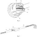
- Fig. 2 is a schematic diagram of an isolated waterproof cable for a wire provided by the second embodiment of the present application.
- the isolated waterproof cable for a wire illustrated includes two wire bodies 11, and a corresponding female socket 14 or male socket is provided at an end where the two wire bodies 11 are connected.
- the wire body connecting the female socket 14 forms a female wire assembly 1
- the wire body connecting the male socket forms a male wire assembly 2.
- the isolated waterproof cable for a wire includes two wire assemblies, and a sealing structure is provided for each wire assembly to seal each conductive wire in each wire assembly or each connector connected with the conductive wire.
- the isolated waterproof cable for a wire in an embodiment of the present application can also include only one wire assembly, which can be a female wire assembly or a male wire assembly.
- the sealing structure is provided within the female socket or the male socket connected with this wire assembly to seal the connector or the conductive wire, while a corresponding male socket or female socket of a wire assembly connected therewith can be not provided with the above sealing structure.
- the female wire assembly 1 will be described below as an example.
- Fig. 3 is an exploded schematic diagram of the isolated waterproof cable for a wire shown in Fig. 2 .
- Fig. 3 is an exploded schematic diagram of the female wire assembly 1.
- the female wire assembly 1 includes a wire body 11, a female socket 14 and a plurality of connectors 12.
- the wire body 11 includes at least one core wire 110, and all the core wires 110 are enclosed by a protective sheath 111.
- the protective sheath 111 is used to protect the wire body 11 to improve the insulation performance, wear resistance and strength of the wire body 11.
- Each core wire 110 includes a conductive wire 113 and an insulating sheath 112 enclosing the conductive wire 113.
- the female socket 14 is provided at the left end of the wire body 11.
- the number of the connectors 12 equals to that of the conductive wires 113. It can be understood that, the number of the connectors 12 can be larger than that of the conductive wires 113, and in this case, some of the connectors 12 actually do not work.
- the sealing structure is partially or entirely provided within the female socket 14, which can thereby protect the sealing structure.
- the sealing structure can be set as needed.
- a sealing ring is provided for each connector 12 or conductive wire 113.
- a segment of the connector 12 is provided within the connector mounting base 13 through injection molding, and the connector mounting base 13 is then sealingly connected to the female socket 14.
- the injection molding here includes potting sealant.
- potting sealant is also called pouring sealant.
- a groove for potting is called a potting groove 16, and a sealant part 15 is formed after potting sealants in the potting groove 16.
- the sealing structure is formed through pouring sealant to cut off the siphon passage.
- the connection part between the connector 12 and the conductive wire 113 is located within the female socket 14 and sealed within the female socket 14 through pouring sealant. That is to say, the gap between adjacent connectors 12 and/or between adjacent conductive wires 113 is eliminated by forming a sealant part 15 within the female socket 14.
- the siphon passage is completely cut off.
- water vapor from outside cannot pass through the sealant part 15, so that an isolated waterproof cable for a wire is realized.
- an end of the conductive wire 113 is not enclosed by the insulating sheath 112, and an end of the insulating sheath 112 is sealed within the sealant part 15 inside the female socket 14.
- the sealant part 15 seals the end of the insulating sheath 112 at the same time and prevents water vapor from entering between the insulating sheath 112 and the conductive wire 113.
- water vapor cannot enter between the insulating sheath 112 and the conductive wire 113.
- the isolated waterproof cable for a wire can further include a connector mounting base 13.
- the connector mounting base 13 is used to mount the connector 12, so that each connector 12 is in a setting position and adjacent connectors 12 are prevented from contacting with each other.
- the connector mounting base 13 is made of insulating material.
- the connector mounting base 13 is provided within the female socket 14 or male socket, and the connector mounting base 13 and the inner wall of the female socket 14 or the male socket forms a potting groove 16. It can be understood that the gap between the radial periphery of the connector mounting base 13 and the inner wall of the female socket 14 or male socket is small, to avoid the sealant from flowing through the gap into the female socket 14 or the male socket during potting.
- the size of the cross section of the potting groove 16 is larger than that of the radial periphery of the connector mounting base 13, so that the connector mounting base 13 or the radical protrusion thereof blocks one end of the potting groove 16.
- the seal 100 is a sealing shell 17 formed by two cover plates in a snap-fit manner, which is convenient for disassembly and assembly and maintenance at a later stage. Description will be made below in conjunction with Figs. 7- 9 .
- Fig. 7 is a schematic diagram of an isolated waterproof cable for a wire provided by the third embodiment of the present application.
- the illustrated isolated waterproof cable for a wire includes two wire bodies 11, the conductive wires 113 of the two wire bodies 11 are integrally connected through the connectors 13, and a sealing shell 17 is provided on an end where the two wire bodies 11 are connected to each other.
- a sealing structure is provided between each wire body 11 and the sealing shell 17 to seal each conductive wire 113 in each wire body 11 or each connector 12 connected to the conductive wire 113.
- Fig. 8 is an exploded schematic diagram of the isolated waterproof cable for a wire shown in Fig. 7 .
- the isolated waterproof cable for a wire includes a wire body 11, a sealing shell 17 and connectors 12.
- the wire body 11 includes at least one core wire 110, and all the core wires 110 are enclosed by a protective sheath 111.
- the protective sheath 111 is used to protect the wire body 11 to improve the insulation performance, wear resistance and strength of the wire body 11, but it is not required always.
- Each core wire 110 includes a conductive wire 113 and an insulating sheath 112 enclosing the conductive wire 113.
- the sealing structure is partially or entirely provided within the sealing shell 17, which can thereby protect the sealing structure.
- the sealing structure can be set as needed.
- a sealing ring can be provided for each connector 12 or conductive wire 113.
- a segment of the connector 12 can be directly sealed and connected within the sealing shell 17 by other means. Embodiments of the present application are not limited thereto.
- the sealing structure is formed through pouring sealant to cut off the siphon passage.
- the connection part between the connector 12 and the conductive wire 113 is located within the sealing shell 17 and sealed within the sealing shell 17 through pouring sealant. That is to say, the gap between adjacent connectors 12 and/or between adjacent conductive wires 113 is eliminated by forming a sealant part 15 within the sealing shell 17.
- the siphon passage is completely cut off. Water vapor from outside cannot pass through the sealant part 15, so that an isolated waterproof cable for a wire is realized.
- an end of the conductive wire 113 is not enclosed by the insulating sheath 112, and an end of the insulating sheath 112 is sealed within the sealant part 15 inside the sealing shell 17.
- the sealant part 15 seals the end of the insulating sheath 112 at the same time and prevents water vapor from entering between the insulating sheath 112 and the conductive wire 113.
- water vapor cannot enter between the insulating sheath 112 and the conductive wire 113.
- the connector 12 is a PCB, one end of which is welded with a conductive wire 113 of one wire body 11, and the other end of which is welded with a conductive wire 113 of another wire body 11.
- the connector 12 forms, with the inner wall of the sealing shell 17, a potting groove 16 for potting sealant.
- An embodiment of the present application further provides an electrical device, which includes the isolated waterproof cable for a wire described above.
- the electrical device includes a wire body 11, a seal 110, at least one connector 12 and a housing 3.
- the wire body 11 includes at least one core wire 110, each core wire 110 includes a conductive wire 113 and an insulating sheath 112 provided outside the conductive wire 113.
- the seal 100 is provided at an end of the wire body 11, and is sealingly engaged with the housing 3 of the electrical device, the wire body 11 is extended from the seal 100 to the inside of the electrical device.
- At least one connector 12 is connected with the conductive wire 113, and a segment of the connector 12 or the conductive wire 113 is sealed within the seal 100.
- the seal 100 is engaged with the housing 3 of the electrical device.
- any suitable structure can be used to seal the connector 12 or conductive wire 113.
- connection part between the connector 12 and the conductive wire 113 is located within the seal 100 and is sealed within the seal 100 through pouring sealant, wherein, optionally, an end of the conductive wire 113 is not enclosed by the insulating sheath 112, and an end of the insulating sheath 112 is sealed within a sealant part 15 inside the seal 100.
- the seal 100 is a female socket 14 or a male socket.
- connection part between the connector 12 and the conductive wire 113 is located within the female socket 14 or the male socket and is sealed within the female socket 14 or the male socket through pouring sealant, wherein an end of the conductive wire 113 is not enclosed by the insulating sheath 112, and an end of the insulating sheath 112 is sealed within the sealant part 15 within the female socket 14 or the male socket.
- the device includes a connector mounting base 13 on which the connector 12 is mounted.
- the connector mounting base 13 is provided within the female socket 14 or the male socket, and forms the potting groove 16 together with the inner wall of the female socket 14 or the male socket.
- the electrical device is a camera.
- a wire mount 4 is provided on a camera housing 3, and the female socket 14 or the male socket is mounted on the wire mount 4 through a waterproof cover 5.
- the waterproof cover 5 can be screwed to the wire mount 4 by thread engagement.
- the waterproof cover 5 is sealingly engaged with the male wire assembly 2 or throwing lines outside the male wire assembly 2 through a first sealing ring 6.
- the waterproof cover 5 is sealingly engaged with the camera housing 3 through a third sealing ring 8.
- the camera housing 3 is sealingly engaged with the male socket 14 through a second sealing ring 7.
- the conductive wire 113 is conducted through mutual contact between corresponding connectors within the female socket 14 and the male socket.
- the waterproof cover 5 can be screwed to the wire mount 4 by thread engagement. As shown in Fig. 13 , the waterproof cover 5 is screwed to the wire mount 4 by the engagement of an internal thread 51 on the waterproof cover 5 with an external thread 41 on the wire mount 4.
- the camera housing 3 is sealingly engaged with the female socket 14 though the second sealing ring 7. As shown in Fig. 12 , it can be understood that the camera housing 3 is sealingly engaged with the female wire assembly 1 though the second sealing ring 7.
- the isolated waterproof cable for a wire in the present application prevents water vapor from flowing along the conductive wire by sealing a segment of the connector or the conductive wire, thereby providing good waterproof performance, for example, the camera fogging problem can be well solved.
- the isolated waterproof cable for a wire in the present application is applicable to various cameras, for example, a camera with a bracket, a hemispherical camera and the like.
- the female socket and the male socket can be fixed onto the camera housing 3 directly or through the waterproof cover 5.
- the female socket 14 and the male socket can be located outside the camera housing or the camera or at a distance away from the camera housing.
- the seal 100 can be a sealing shell 17 formed by two cover plates in a snap-fit manner. Description will be made below in conjunction with Figs. 7- 9 .
- connection part between the connector 12 and the conductive wire 113 is located within the sealing shell 17 and is sealed within the sealing shelling 17 through pouring sealant, wherein an end of the conductive wire 113 is not enclosed by the insulating sheath 112, and an end of the insulating sheath 112 is sealed within the sealant part 15 within the sealing shell 17.
- the connector 12 is a PCB, one end of which is welded with a conductive wire 113 of one wire body 11, and the other end of which is welded with a conductive wire 113 of another wire body 11 and forms, with the inner wall of the sealing shell 17, a potting groove 16 for potting sealant.
- the electrical device is a camera.
- the isolated waterproof cable for a wire in the present application prevents water vapor from flowing along the conductive wire by sealing a segment of the connector 12 or the conductive wire 13, thereby providing good waterproof performance, for example, the camera fogging problem can be well solved.
- the isolated waterproof cable for a wire in the present application is applicable to various cameras, for example, a camera with a bracket, a hemispherical camera and the like.
- the sealing shell 17 can be fixed to the camera housing 3 directly or through the waterproof cover 5.
- the sealing shell 17 can be located outside the camera housing 3 or the camera or at a distance away from the camera.
Landscapes
- Physics & Mathematics (AREA)
- General Physics & Mathematics (AREA)
- Chemical & Material Sciences (AREA)
- Dispersion Chemistry (AREA)
- Connector Housings Or Holding Contact Members (AREA)
Claims (3)
- Eine Kamera, umfassend:
ein isoliertes wasserdichtes Kabel für einen Draht; wobei das isolierte wasserdichte Kabel umfasst:einen Drahtkörper (11), der mindestens einen Kerndraht (110) umfasst, wobei jeder Kerndraht (110) einen leitenden Draht (113) und einen isolierenden Mantel (112) umfasst, der den leitenden Draht (113) umschließt;eine Dichtung (100), die an einem Ende des Drahtkörpers (11) vorgesehen ist, wobei die Dichtung (100) eine weibliche Buchse (14) oder eine männliche Buchse ist, undmindestens einen Verbinder (12), der mit dem leitenden Draht (113) verbunden ist, und ein Verbindungsteil zwischen dem Verbinder (12) und dem leitenden Draht (113) innerhalb der Dichtung (100) angeordnet und innerhalb der Dichtung (100) durch Ausgießen von Dichtungsmittel abgedichtet ist,das wasserdichte Kabel ferner eine Verbinderbefestigungsbasis (13) umfasst, an der der Verbinder (12) befestigt ist, wobei die Verbinderbefestigungsbasis (13) innerhalb der Dichtung (100) vorgesehen ist und zusammen mit einer Innenwand der Dichtung (100) eine Vergussnut (16) bildet, und ein Dichtungsteil (15) nach dem Vergießen von Dichtungsmitteln in der Vergussnut (16) gebildet wird;wobei ein Segment des Verbinders (12) innerhalb der Verbindermontagebasis (13) durch Spritzgießen vorgesehen ist und die Verbindermontagebasis (13) abdichtend mit der Dichtung (100) verbunden ist,wobei die Dichtung (100) abdichtend mit einem Gehäuse (3) der Kamera in Eingriff steht und der Drahtkörper (11) sich von der Dichtung (100) in das Innere der Kamera erstreckt;wobei eine Drahthalterung (4) an dem Gehäuse (3) der Kamera vorgesehen ist und die Dichtung (100) an der Drahthalterung (4) durch eine wasserdichte Abdeckung (5) angebracht ist, wobei die wasserdichte Abdeckung (5) an die Drahthalterung (4) durch Gewindeeingriff geschraubt werden kann. - Die Kamera nach Anspruch 1, wobei ein Ende des leitenden Drahts (113) nicht von der isolierenden Umhüllung (112) umschlossen ist und ein Ende der isolierenden Umhüllung (112) innerhalb des Dichtungsteils (15) innerhalb der Dichtung (100) abgedichtet ist.
- Die Kamera nach Anspruch 1, umfassend zwei Drahtkörper (11), von denen einer mit der weiblichen Buchse (14) und der andere mit dem der weiblichen Buchse (14) entsprechenden männlichen Buchse verbunden ist, wobei das Dichtungsteil (15) innerhalb der Buchse (14) und des Steckers vorgesehen ist.
Applications Claiming Priority (3)
| Application Number | Priority Date | Filing Date | Title |
|---|---|---|---|
| CN201720075706.3U CN206558774U (zh) | 2017-01-20 | 2017-01-20 | 一种隔离式线材防水结构及具有其的用电设备 |
| CN201720086131.5U CN206412541U (zh) | 2017-01-20 | 2017-01-20 | 一种隔离式线材防水结构及具有其的用电设备 |
| PCT/CN2018/071334 WO2018133671A1 (zh) | 2017-01-20 | 2018-01-04 | 一种隔离式线材防水结构及具有其的用电设备 |
Publications (3)
| Publication Number | Publication Date |
|---|---|
| EP3573192A1 EP3573192A1 (de) | 2019-11-27 |
| EP3573192A4 EP3573192A4 (de) | 2020-04-08 |
| EP3573192B1 true EP3573192B1 (de) | 2023-03-15 |
Family
ID=62908490
Family Applications (1)
| Application Number | Title | Priority Date | Filing Date |
|---|---|---|---|
| EP18741292.9A Active EP3573192B1 (de) | 2017-01-20 | 2018-01-04 | Kamera |
Country Status (3)
| Country | Link |
|---|---|
| US (1) | US10587072B2 (de) |
| EP (1) | EP3573192B1 (de) |
| WO (1) | WO2018133671A1 (de) |
Families Citing this family (1)
| Publication number | Priority date | Publication date | Assignee | Title |
|---|---|---|---|---|
| EP4597771A1 (de) * | 2022-09-28 | 2025-08-06 | Stella Importação e Exportação de Luminárias Ltda | Antikondensations-isolierblöcke zur verwendung am stromkabel von leuchten |
Citations (4)
| Publication number | Priority date | Publication date | Assignee | Title |
|---|---|---|---|---|
| JPH09106853A (ja) * | 1995-10-09 | 1997-04-22 | Yazaki Corp | シールドコネクタ |
| US20100041268A1 (en) * | 2005-04-28 | 2010-02-18 | Autonetworks Technologies, Ltd | Electrical Equipment |
| WO2013080443A1 (en) * | 2011-11-30 | 2013-06-06 | Yazaki Corporation | Connector and method of filling potting material of connector |
| CN206412541U (zh) * | 2017-01-20 | 2017-08-15 | 杭州海康威视数字技术股份有限公司 | 一种隔离式线材防水结构及具有其的用电设备 |
Family Cites Families (12)
| Publication number | Priority date | Publication date | Assignee | Title |
|---|---|---|---|---|
| US5217387A (en) * | 1992-04-28 | 1993-06-08 | Hull Harold L | Water resistant extension cord connector housing |
| JP3081775B2 (ja) * | 1995-05-29 | 2000-08-28 | 矢崎総業株式会社 | 防水保護カバー |
| US7285725B1 (en) * | 2005-03-22 | 2007-10-23 | Rick Saman | Weatherproof and restraining apparatus for electrical plugs |
| US7883608B2 (en) * | 2006-11-07 | 2011-02-08 | The Patent Store Llc | Cathodic protection systems |
| US8502072B2 (en) * | 2009-05-29 | 2013-08-06 | General Dynamics Advanced Information Systems, Inc. | Spliced cable with overmolded water proof coating and method for making the same |
| JP6121660B2 (ja) | 2012-07-02 | 2017-04-26 | 矢崎総業株式会社 | 防水コネクタ |
| CN203645050U (zh) | 2013-11-22 | 2014-06-11 | 陈奇 | 一种灌封式水密接插件 |
| CN203800287U (zh) | 2014-03-19 | 2014-08-27 | 东莞龙杰电子有限公司 | 防水电源线 |
| CN103996945B (zh) | 2014-06-16 | 2016-03-30 | 四川大学 | 一种螺纹辅助的弹性圆环插孔连接器 |
| CN204559075U (zh) * | 2014-11-18 | 2015-08-12 | 艾维新能源科技南京有限公司 | 一种线缆水汽阻断装置 |
| CN205212056U (zh) | 2015-10-22 | 2016-05-04 | 安费诺电子装配(厦门)有限公司 | 一种防水连接线束 |
| CN206558774U (zh) | 2017-01-20 | 2017-10-13 | 杭州海康威视数字技术股份有限公司 | 一种隔离式线材防水结构及具有其的用电设备 |
-
2018
- 2018-01-04 EP EP18741292.9A patent/EP3573192B1/de active Active
- 2018-01-04 US US16/473,951 patent/US10587072B2/en active Active
- 2018-01-04 WO PCT/CN2018/071334 patent/WO2018133671A1/zh not_active Ceased
Patent Citations (4)
| Publication number | Priority date | Publication date | Assignee | Title |
|---|---|---|---|---|
| JPH09106853A (ja) * | 1995-10-09 | 1997-04-22 | Yazaki Corp | シールドコネクタ |
| US20100041268A1 (en) * | 2005-04-28 | 2010-02-18 | Autonetworks Technologies, Ltd | Electrical Equipment |
| WO2013080443A1 (en) * | 2011-11-30 | 2013-06-06 | Yazaki Corporation | Connector and method of filling potting material of connector |
| CN206412541U (zh) * | 2017-01-20 | 2017-08-15 | 杭州海康威视数字技术股份有限公司 | 一种隔离式线材防水结构及具有其的用电设备 |
Also Published As
| Publication number | Publication date |
|---|---|
| EP3573192A1 (de) | 2019-11-27 |
| US20190326705A1 (en) | 2019-10-24 |
| US10587072B2 (en) | 2020-03-10 |
| WO2018133671A1 (zh) | 2018-07-26 |
| EP3573192A4 (de) | 2020-04-08 |
Similar Documents
| Publication | Publication Date | Title |
|---|---|---|
| CN102220963B (zh) | 电控单元 | |
| JP2015035940A (ja) | 高精細度ビデオ/オーディオ再生装置のためのhdmiケーブル、hdmiコネクター及びhdmiインターフェース | |
| CN203445320U (zh) | 一种防水连接器 | |
| CN206685565U (zh) | 电连接器 | |
| US7708593B1 (en) | Electrical connector having an encapsulant to seal the connector | |
| CN107431288A (zh) | Hv线缆套件 | |
| US20130050956A1 (en) | Photovoltaic Junction Module | |
| EP3573192B1 (de) | Kamera | |
| KR101004602B1 (ko) | 다면 패킹구조 방수 커넥터 | |
| CN206412541U (zh) | 一种隔离式线材防水结构及具有其的用电设备 | |
| CN206558774U (zh) | 一种隔离式线材防水结构及具有其的用电设备 | |
| KR101614737B1 (ko) | Fpcb 일체형 female 커넥터를 이용한 케이블 연결구 제조방법 및 이를 이용한 케이블 연결구 | |
| CN207781725U (zh) | 用于电池包的接线端子和电池包 | |
| CN201134490Y (zh) | 同轴连接器 | |
| CN206022755U (zh) | 一种高密封性航空连接线 | |
| CN102025074A (zh) | 电连接器组件的密封结构及其密封方法 | |
| CN110380276B (zh) | 一种多功能复合型连接器 | |
| CN209183829U (zh) | 一种高压接线盒连接器 | |
| CN102610301A (zh) | 大型射电望远镜主动面系统专用电缆 | |
| CN203445275U (zh) | 一种用于高清视频/音频播放设备的hdmi接口 | |
| CN110416801A (zh) | 电连接器和具有其的车辆 | |
| CN105071109A (zh) | 一种摄像头防水连接装置及其使用方法 | |
| CN211296102U (zh) | 一种母线槽的连接机构 | |
| CN202697089U (zh) | 电控盒的防水机构及具有该机构的热水器 | |
| CN102723632B (zh) | 一种防渗电连接端子及其金属端子、电子装置 |
Legal Events
| Date | Code | Title | Description |
|---|---|---|---|
| STAA | Information on the status of an ep patent application or granted ep patent |
Free format text: STATUS: THE INTERNATIONAL PUBLICATION HAS BEEN MADE |
|
| PUAI | Public reference made under article 153(3) epc to a published international application that has entered the european phase |
Free format text: ORIGINAL CODE: 0009012 |
|
| STAA | Information on the status of an ep patent application or granted ep patent |
Free format text: STATUS: REQUEST FOR EXAMINATION WAS MADE |
|
| 17P | Request for examination filed |
Effective date: 20190717 |
|
| AK | Designated contracting states |
Kind code of ref document: A1 Designated state(s): AL AT BE BG CH CY CZ DE DK EE ES FI FR GB GR HR HU IE IS IT LI LT LU LV MC MK MT NL NO PL PT RO RS SE SI SK SM TR |
|
| AX | Request for extension of the european patent |
Extension state: BA ME |
|
| A4 | Supplementary search report drawn up and despatched |
Effective date: 20200309 |
|
| RIC1 | Information provided on ipc code assigned before grant |
Ipc: H01R 12/53 20110101ALI20200303BHEP Ipc: H01R 13/506 20060101ALN20200303BHEP Ipc: H02G 15/18 20060101ALN20200303BHEP Ipc: H01R 13/622 20060101ALN20200303BHEP Ipc: H01R 4/70 20060101AFI20200303BHEP Ipc: H01R 13/52 20060101ALN20200303BHEP |
|
| DAV | Request for validation of the european patent (deleted) | ||
| DAX | Request for extension of the european patent (deleted) | ||
| STAA | Information on the status of an ep patent application or granted ep patent |
Free format text: STATUS: EXAMINATION IS IN PROGRESS |
|
| 17Q | First examination report despatched |
Effective date: 20210122 |
|
| REG | Reference to a national code |
Ref country code: DE Ref legal event code: R079 Ref document number: 602018047240 Country of ref document: DE Free format text: PREVIOUS MAIN CLASS: H01R0013520000 Ipc: G03B0017080000 |
|
| RIC1 | Information provided on ipc code assigned before grant |
Ipc: H02G 15/18 20060101ALN20220828BHEP Ipc: H01R 13/52 20060101ALN20220828BHEP Ipc: H01R 13/506 20060101ALN20220828BHEP Ipc: H01R 13/622 20060101ALN20220828BHEP Ipc: H01R 12/53 20110101ALI20220828BHEP Ipc: H01R 4/70 20060101ALI20220828BHEP Ipc: G03B 17/08 20060101AFI20220828BHEP |
|
| RIC1 | Information provided on ipc code assigned before grant |
Ipc: H02G 15/18 20060101ALN20220905BHEP Ipc: H01R 13/52 20060101ALN20220905BHEP Ipc: H01R 13/506 20060101ALN20220905BHEP Ipc: H01R 13/622 20060101ALN20220905BHEP Ipc: H01R 12/53 20110101ALI20220905BHEP Ipc: H01R 4/70 20060101ALI20220905BHEP Ipc: G03B 17/08 20060101AFI20220905BHEP |
|
| INTG | Intention to grant announced |
Effective date: 20220928 |
|
| GRAS | Grant fee paid |
Free format text: ORIGINAL CODE: EPIDOSNIGR3 |
|
| STAA | Information on the status of an ep patent application or granted ep patent |
Free format text: STATUS: GRANT OF PATENT IS INTENDED |
|
| GRAA | (expected) grant |
Free format text: ORIGINAL CODE: 0009210 |
|
| STAA | Information on the status of an ep patent application or granted ep patent |
Free format text: STATUS: THE PATENT HAS BEEN GRANTED |
|
| AK | Designated contracting states |
Kind code of ref document: B1 Designated state(s): AL AT BE BG CH CY CZ DE DK EE ES FI FR GB GR HR HU IE IS IT LI LT LU LV MC MK MT NL NO PL PT RO RS SE SI SK SM TR |
|
| REG | Reference to a national code |
Ref country code: CH Ref legal event code: EP Ref country code: GB Ref legal event code: FG4D |
|
| REG | Reference to a national code |
Ref country code: DE Ref legal event code: R096 Ref document number: 602018047240 Country of ref document: DE |
|
| REG | Reference to a national code |
Ref country code: IE Ref legal event code: FG4D |
|
| REG | Reference to a national code |
Ref country code: AT Ref legal event code: REF Ref document number: 1554346 Country of ref document: AT Kind code of ref document: T Effective date: 20230415 |
|
| P01 | Opt-out of the competence of the unified patent court (upc) registered |
Effective date: 20230424 |
|
| REG | Reference to a national code |
Ref country code: LT Ref legal event code: MG9D |
|
| REG | Reference to a national code |
Ref country code: NL Ref legal event code: MP Effective date: 20230315 |
|
| PG25 | Lapsed in a contracting state [announced via postgrant information from national office to epo] |
Ref country code: RS Free format text: LAPSE BECAUSE OF FAILURE TO SUBMIT A TRANSLATION OF THE DESCRIPTION OR TO PAY THE FEE WITHIN THE PRESCRIBED TIME-LIMIT Effective date: 20230315 Ref country code: NO Free format text: LAPSE BECAUSE OF FAILURE TO SUBMIT A TRANSLATION OF THE DESCRIPTION OR TO PAY THE FEE WITHIN THE PRESCRIBED TIME-LIMIT Effective date: 20230615 Ref country code: LV Free format text: LAPSE BECAUSE OF FAILURE TO SUBMIT A TRANSLATION OF THE DESCRIPTION OR TO PAY THE FEE WITHIN THE PRESCRIBED TIME-LIMIT Effective date: 20230315 Ref country code: LT Free format text: LAPSE BECAUSE OF FAILURE TO SUBMIT A TRANSLATION OF THE DESCRIPTION OR TO PAY THE FEE WITHIN THE PRESCRIBED TIME-LIMIT Effective date: 20230315 Ref country code: HR Free format text: LAPSE BECAUSE OF FAILURE TO SUBMIT A TRANSLATION OF THE DESCRIPTION OR TO PAY THE FEE WITHIN THE PRESCRIBED TIME-LIMIT Effective date: 20230315 |
|
| REG | Reference to a national code |
Ref country code: AT Ref legal event code: MK05 Ref document number: 1554346 Country of ref document: AT Kind code of ref document: T Effective date: 20230315 |
|
| PG25 | Lapsed in a contracting state [announced via postgrant information from national office to epo] |
Ref country code: SE Free format text: LAPSE BECAUSE OF FAILURE TO SUBMIT A TRANSLATION OF THE DESCRIPTION OR TO PAY THE FEE WITHIN THE PRESCRIBED TIME-LIMIT Effective date: 20230315 Ref country code: NL Free format text: LAPSE BECAUSE OF FAILURE TO SUBMIT A TRANSLATION OF THE DESCRIPTION OR TO PAY THE FEE WITHIN THE PRESCRIBED TIME-LIMIT Effective date: 20230315 Ref country code: GR Free format text: LAPSE BECAUSE OF FAILURE TO SUBMIT A TRANSLATION OF THE DESCRIPTION OR TO PAY THE FEE WITHIN THE PRESCRIBED TIME-LIMIT Effective date: 20230616 Ref country code: FI Free format text: LAPSE BECAUSE OF FAILURE TO SUBMIT A TRANSLATION OF THE DESCRIPTION OR TO PAY THE FEE WITHIN THE PRESCRIBED TIME-LIMIT Effective date: 20230315 |
|
| PG25 | Lapsed in a contracting state [announced via postgrant information from national office to epo] |
Ref country code: SM Free format text: LAPSE BECAUSE OF FAILURE TO SUBMIT A TRANSLATION OF THE DESCRIPTION OR TO PAY THE FEE WITHIN THE PRESCRIBED TIME-LIMIT Effective date: 20230315 Ref country code: RO Free format text: LAPSE BECAUSE OF FAILURE TO SUBMIT A TRANSLATION OF THE DESCRIPTION OR TO PAY THE FEE WITHIN THE PRESCRIBED TIME-LIMIT Effective date: 20230315 Ref country code: PT Free format text: LAPSE BECAUSE OF FAILURE TO SUBMIT A TRANSLATION OF THE DESCRIPTION OR TO PAY THE FEE WITHIN THE PRESCRIBED TIME-LIMIT Effective date: 20230717 Ref country code: ES Free format text: LAPSE BECAUSE OF FAILURE TO SUBMIT A TRANSLATION OF THE DESCRIPTION OR TO PAY THE FEE WITHIN THE PRESCRIBED TIME-LIMIT Effective date: 20230315 Ref country code: EE Free format text: LAPSE BECAUSE OF FAILURE TO SUBMIT A TRANSLATION OF THE DESCRIPTION OR TO PAY THE FEE WITHIN THE PRESCRIBED TIME-LIMIT Effective date: 20230315 Ref country code: CZ Free format text: LAPSE BECAUSE OF FAILURE TO SUBMIT A TRANSLATION OF THE DESCRIPTION OR TO PAY THE FEE WITHIN THE PRESCRIBED TIME-LIMIT Effective date: 20230315 Ref country code: AT Free format text: LAPSE BECAUSE OF FAILURE TO SUBMIT A TRANSLATION OF THE DESCRIPTION OR TO PAY THE FEE WITHIN THE PRESCRIBED TIME-LIMIT Effective date: 20230315 |
|
| PG25 | Lapsed in a contracting state [announced via postgrant information from national office to epo] |
Ref country code: SK Free format text: LAPSE BECAUSE OF FAILURE TO SUBMIT A TRANSLATION OF THE DESCRIPTION OR TO PAY THE FEE WITHIN THE PRESCRIBED TIME-LIMIT Effective date: 20230315 Ref country code: PL Free format text: LAPSE BECAUSE OF FAILURE TO SUBMIT A TRANSLATION OF THE DESCRIPTION OR TO PAY THE FEE WITHIN THE PRESCRIBED TIME-LIMIT Effective date: 20230315 Ref country code: IS Free format text: LAPSE BECAUSE OF FAILURE TO SUBMIT A TRANSLATION OF THE DESCRIPTION OR TO PAY THE FEE WITHIN THE PRESCRIBED TIME-LIMIT Effective date: 20230715 |
|
| REG | Reference to a national code |
Ref country code: DE Ref legal event code: R097 Ref document number: 602018047240 Country of ref document: DE |
|
| PLBE | No opposition filed within time limit |
Free format text: ORIGINAL CODE: 0009261 |
|
| STAA | Information on the status of an ep patent application or granted ep patent |
Free format text: STATUS: NO OPPOSITION FILED WITHIN TIME LIMIT |
|
| PG25 | Lapsed in a contracting state [announced via postgrant information from national office to epo] |
Ref country code: SI Free format text: LAPSE BECAUSE OF FAILURE TO SUBMIT A TRANSLATION OF THE DESCRIPTION OR TO PAY THE FEE WITHIN THE PRESCRIBED TIME-LIMIT Effective date: 20230315 Ref country code: DK Free format text: LAPSE BECAUSE OF FAILURE TO SUBMIT A TRANSLATION OF THE DESCRIPTION OR TO PAY THE FEE WITHIN THE PRESCRIBED TIME-LIMIT Effective date: 20230315 |
|
| 26N | No opposition filed |
Effective date: 20231218 |
|
| PG25 | Lapsed in a contracting state [announced via postgrant information from national office to epo] |
Ref country code: IT Free format text: LAPSE BECAUSE OF FAILURE TO SUBMIT A TRANSLATION OF THE DESCRIPTION OR TO PAY THE FEE WITHIN THE PRESCRIBED TIME-LIMIT Effective date: 20230315 |
|
| PG25 | Lapsed in a contracting state [announced via postgrant information from national office to epo] |
Ref country code: MC Free format text: LAPSE BECAUSE OF FAILURE TO SUBMIT A TRANSLATION OF THE DESCRIPTION OR TO PAY THE FEE WITHIN THE PRESCRIBED TIME-LIMIT Effective date: 20230315 |
|
| PG25 | Lapsed in a contracting state [announced via postgrant information from national office to epo] |
Ref country code: MC Free format text: LAPSE BECAUSE OF FAILURE TO SUBMIT A TRANSLATION OF THE DESCRIPTION OR TO PAY THE FEE WITHIN THE PRESCRIBED TIME-LIMIT Effective date: 20230315 |
|
| REG | Reference to a national code |
Ref country code: CH Ref legal event code: PL |
|
| PG25 | Lapsed in a contracting state [announced via postgrant information from national office to epo] |
Ref country code: LU Free format text: LAPSE BECAUSE OF NON-PAYMENT OF DUE FEES Effective date: 20240104 |
|
| GBPC | Gb: european patent ceased through non-payment of renewal fee |
Effective date: 20240104 |
|
| PG25 | Lapsed in a contracting state [announced via postgrant information from national office to epo] |
Ref country code: LU Free format text: LAPSE BECAUSE OF NON-PAYMENT OF DUE FEES Effective date: 20240104 |
|
| PG25 | Lapsed in a contracting state [announced via postgrant information from national office to epo] |
Ref country code: GB Free format text: LAPSE BECAUSE OF NON-PAYMENT OF DUE FEES Effective date: 20240104 |
|
| PG25 | Lapsed in a contracting state [announced via postgrant information from national office to epo] |
Ref country code: BE Free format text: LAPSE BECAUSE OF NON-PAYMENT OF DUE FEES Effective date: 20240131 |
|
| PG25 | Lapsed in a contracting state [announced via postgrant information from national office to epo] |
Ref country code: FR Free format text: LAPSE BECAUSE OF NON-PAYMENT OF DUE FEES Effective date: 20240131 |
|
| PG25 | Lapsed in a contracting state [announced via postgrant information from national office to epo] |
Ref country code: CH Free format text: LAPSE BECAUSE OF NON-PAYMENT OF DUE FEES Effective date: 20240131 |
|
| PG25 | Lapsed in a contracting state [announced via postgrant information from national office to epo] |
Ref country code: GB Free format text: LAPSE BECAUSE OF NON-PAYMENT OF DUE FEES Effective date: 20240104 Ref country code: FR Free format text: LAPSE BECAUSE OF NON-PAYMENT OF DUE FEES Effective date: 20240131 Ref country code: CH Free format text: LAPSE BECAUSE OF NON-PAYMENT OF DUE FEES Effective date: 20240131 Ref country code: BE Free format text: LAPSE BECAUSE OF NON-PAYMENT OF DUE FEES Effective date: 20240131 |
|
| REG | Reference to a national code |
Ref country code: BE Ref legal event code: MM Effective date: 20240131 |
|
| PG25 | Lapsed in a contracting state [announced via postgrant information from national office to epo] |
Ref country code: BG Free format text: LAPSE BECAUSE OF FAILURE TO SUBMIT A TRANSLATION OF THE DESCRIPTION OR TO PAY THE FEE WITHIN THE PRESCRIBED TIME-LIMIT Effective date: 20230315 |
|
| PG25 | Lapsed in a contracting state [announced via postgrant information from national office to epo] |
Ref country code: BG Free format text: LAPSE BECAUSE OF FAILURE TO SUBMIT A TRANSLATION OF THE DESCRIPTION OR TO PAY THE FEE WITHIN THE PRESCRIBED TIME-LIMIT Effective date: 20230315 |
|
| PG25 | Lapsed in a contracting state [announced via postgrant information from national office to epo] |
Ref country code: IE Free format text: LAPSE BECAUSE OF NON-PAYMENT OF DUE FEES Effective date: 20240104 |
|
| PG25 | Lapsed in a contracting state [announced via postgrant information from national office to epo] |
Ref country code: IE Free format text: LAPSE BECAUSE OF NON-PAYMENT OF DUE FEES Effective date: 20240104 |
|
| PGFP | Annual fee paid to national office [announced via postgrant information from national office to epo] |
Ref country code: DE Payment date: 20250116 Year of fee payment: 8 |
|
| PG25 | Lapsed in a contracting state [announced via postgrant information from national office to epo] |
Ref country code: CY Free format text: LAPSE BECAUSE OF FAILURE TO SUBMIT A TRANSLATION OF THE DESCRIPTION OR TO PAY THE FEE WITHIN THE PRESCRIBED TIME-LIMIT; INVALID AB INITIO Effective date: 20180104 |
|
| PG25 | Lapsed in a contracting state [announced via postgrant information from national office to epo] |
Ref country code: HU Free format text: LAPSE BECAUSE OF FAILURE TO SUBMIT A TRANSLATION OF THE DESCRIPTION OR TO PAY THE FEE WITHIN THE PRESCRIBED TIME-LIMIT; INVALID AB INITIO Effective date: 20180104 |
|
| PG25 | Lapsed in a contracting state [announced via postgrant information from national office to epo] |
Ref country code: TR Free format text: LAPSE BECAUSE OF FAILURE TO SUBMIT A TRANSLATION OF THE DESCRIPTION OR TO PAY THE FEE WITHIN THE PRESCRIBED TIME-LIMIT Effective date: 20230315 |