EP3573172B1 - Heizungsregelungsverfahren und heizungsregelungsvorrichtung - Google Patents
Heizungsregelungsverfahren und heizungsregelungsvorrichtung Download PDFInfo
- Publication number
- EP3573172B1 EP3573172B1 EP19150225.1A EP19150225A EP3573172B1 EP 3573172 B1 EP3573172 B1 EP 3573172B1 EP 19150225 A EP19150225 A EP 19150225A EP 3573172 B1 EP3573172 B1 EP 3573172B1
- Authority
- EP
- European Patent Office
- Prior art keywords
- cycle
- current value
- average current
- value
- battery pack
- Prior art date
- Legal status (The legal status is an assumption and is not a legal conclusion. Google has not performed a legal analysis and makes no representation as to the accuracy of the status listed.)
- Active
Links
Images


Classifications
-
- H—ELECTRICITY
- H05—ELECTRIC TECHNIQUES NOT OTHERWISE PROVIDED FOR
- H05B—ELECTRIC HEATING; ELECTRIC LIGHT SOURCES NOT OTHERWISE PROVIDED FOR; CIRCUIT ARRANGEMENTS FOR ELECTRIC LIGHT SOURCES, IN GENERAL
- H05B1/00—Details of electric heating devices
- H05B1/02—Automatic switching arrangements specially adapted to apparatus ; Control of heating devices
- H05B1/0227—Applications
- H05B1/023—Industrial applications
-
- H—ELECTRICITY
- H01—ELECTRIC ELEMENTS
- H01M—PROCESSES OR MEANS, e.g. BATTERIES, FOR THE DIRECT CONVERSION OF CHEMICAL ENERGY INTO ELECTRICAL ENERGY
- H01M10/00—Secondary cells; Manufacture thereof
- H01M10/42—Methods or arrangements for servicing or maintenance of secondary cells or secondary half-cells
- H01M10/425—Structural combination with electronic components, e.g. electronic circuits integrated to the outside of the casing
-
- H—ELECTRICITY
- H01—ELECTRIC ELEMENTS
- H01M—PROCESSES OR MEANS, e.g. BATTERIES, FOR THE DIRECT CONVERSION OF CHEMICAL ENERGY INTO ELECTRICAL ENERGY
- H01M10/00—Secondary cells; Manufacture thereof
- H01M10/60—Heating or cooling; Temperature control
- H01M10/61—Types of temperature control
- H01M10/615—Heating or keeping warm
-
- H—ELECTRICITY
- H01—ELECTRIC ELEMENTS
- H01M—PROCESSES OR MEANS, e.g. BATTERIES, FOR THE DIRECT CONVERSION OF CHEMICAL ENERGY INTO ELECTRICAL ENERGY
- H01M10/00—Secondary cells; Manufacture thereof
- H01M10/60—Heating or cooling; Temperature control
- H01M10/63—Control systems
- H01M10/633—Control systems characterised by algorithms, flow charts, software details or the like
-
- H—ELECTRICITY
- H01—ELECTRIC ELEMENTS
- H01M—PROCESSES OR MEANS, e.g. BATTERIES, FOR THE DIRECT CONVERSION OF CHEMICAL ENERGY INTO ELECTRICAL ENERGY
- H01M10/00—Secondary cells; Manufacture thereof
- H01M10/60—Heating or cooling; Temperature control
- H01M10/65—Means for temperature control structurally associated with the cells
- H01M10/651—Means for temperature control structurally associated with the cells characterised by parameters specified by a numeric value or mathematical formula, e.g. ratios, sizes or concentrations
-
- H—ELECTRICITY
- H01—ELECTRIC ELEMENTS
- H01M—PROCESSES OR MEANS, e.g. BATTERIES, FOR THE DIRECT CONVERSION OF CHEMICAL ENERGY INTO ELECTRICAL ENERGY
- H01M10/00—Secondary cells; Manufacture thereof
- H01M10/60—Heating or cooling; Temperature control
- H01M10/65—Means for temperature control structurally associated with the cells
- H01M10/657—Means for temperature control structurally associated with the cells by electric or electromagnetic means
- H01M10/6571—Resistive heaters
-
- G—PHYSICS
- G01—MEASURING; TESTING
- G01R—MEASURING ELECTRIC VARIABLES; MEASURING MAGNETIC VARIABLES
- G01R19/00—Arrangements for measuring currents or voltages or for indicating presence or sign thereof
- G01R19/165—Indicating that current or voltage is either above or below a predetermined value or within or outside a predetermined range of values
- G01R19/16528—Indicating that current or voltage is either above or below a predetermined value or within or outside a predetermined range of values using digital techniques or performing arithmetic operations
-
- G—PHYSICS
- G01—MEASURING; TESTING
- G01R—MEASURING ELECTRIC VARIABLES; MEASURING MAGNETIC VARIABLES
- G01R31/00—Arrangements for testing electric properties; Arrangements for locating electric faults; Arrangements for electrical testing characterised by what is being tested not provided for elsewhere
- G01R31/36—Arrangements for testing, measuring or monitoring the electrical condition of accumulators or electric batteries, e.g. capacity or state of charge [SoC]
- G01R31/382—Arrangements for monitoring battery or accumulator variables, e.g. SoC
-
- H—ELECTRICITY
- H01—ELECTRIC ELEMENTS
- H01M—PROCESSES OR MEANS, e.g. BATTERIES, FOR THE DIRECT CONVERSION OF CHEMICAL ENERGY INTO ELECTRICAL ENERGY
- H01M10/00—Secondary cells; Manufacture thereof
- H01M10/42—Methods or arrangements for servicing or maintenance of secondary cells or secondary half-cells
- H01M10/425—Structural combination with electronic components, e.g. electronic circuits integrated to the outside of the casing
- H01M2010/4271—Battery management systems including electronic circuits, e.g. control of current or voltage to keep battery in healthy state, cell balancing
-
- Y—GENERAL TAGGING OF NEW TECHNOLOGICAL DEVELOPMENTS; GENERAL TAGGING OF CROSS-SECTIONAL TECHNOLOGIES SPANNING OVER SEVERAL SECTIONS OF THE IPC; TECHNICAL SUBJECTS COVERED BY FORMER USPC CROSS-REFERENCE ART COLLECTIONS [XRACs] AND DIGESTS
- Y02—TECHNOLOGIES OR APPLICATIONS FOR MITIGATION OR ADAPTATION AGAINST CLIMATE CHANGE
- Y02E—REDUCTION OF GREENHOUSE GAS [GHG] EMISSIONS, RELATED TO ENERGY GENERATION, TRANSMISSION OR DISTRIBUTION
- Y02E60/00—Enabling technologies; Technologies with a potential or indirect contribution to GHG emissions mitigation
- Y02E60/10—Energy storage using batteries
Definitions
- the invention relates to the technical field of battery, and in particular, to a heating control method and a heating control device
- a power battery pack When a power battery pack has a temperature lower than a lower limit of an allowable operating temperature range, the power battery pack cannot work and needs to be heated to a temperature within the allowable operating temperature range before it resumes its operations.
- a method for heating a power battery pack includes: controlling a switch device to instantaneously short a power battery to form a heating circuit, such that an internal resistance of the power battery generates heat when a large current generated by instantaneous shorting flows through the internal resistance, thereby heating the power battery.
- This solution has advantages of high heating speed and even heating.
- Commonly used switch devices include Insulated Gate Bipolar Transistors (IGBTs).
- IGBT's operations are controlled mainly by way of internal resistances of the power battery pack in related art, but such method can only indirectly adjust heating current in the heating circuit and has lower control accuracy.
- US5789092 concerns a method and an equipment for prevention of cooling of electrochemical devices (10).
- the temperature of the electrochemical device (10) is measured and, as the temperature falls below a certain preset lower limit (Tminimum), an additional load (17), which is at least high enough so that the electric current that it produces heats the electrochemical device (10), is connected to the device.
- the additional load (17) is disconnected from the electrochemical device (10) as the temperature has reached a certain preset upper limit (Tmaximum).
- Embodiments of the invention provide a heating control method and a heating control device that can improve accuracy of controlling current in a heating circuit of a battery pack.
- a heating control method includes: acquiring an average current value in a heating circuit of a power battery pack, wherein the average current value comprises an average current value of n th cycle, an average current value of (n-1) th cycle and an average current value of (n-2) th cycle, wherein the n is equal to or greater than 3 and wherein the cycle is a period of time for current sampling; calculating a current output value required for the n th cycle according to the average current value of the nth cycle, the average current value of the (n-1) th cycle, the average current value of the (n-2) th cycle and a preset current value; and outputting a Pulse width Modulation (PWM) signal to a switch device of the heating circuit according to a pre-calibrated PWM control parameter, wherein the pre-calibrated PWM control parameter is corresponding to the current output value required for n th cycle, so that a difference between an actual current value in the heating circuit and
- PWM Pulse width Modulation
- the calculating a current output value required for the n th cycle according to the average current value of the n th cycle, the average current value of the (n-1) th cycle, the n average current value of the (n-2) th cycle and the preset current value may include: setting a difference between the preset current value and the average current value of the n th cycle as n th cycle difference value, setting a difference between the preset current value and the average current value of the (n-1) th cycle as (n-1) th cycle difference value, and setting a difference between the preset current value and the average current value of the (n-2) th cycle as (n-2) th cycle difference value; acquiring a state of charge section of the power battery pack; determining a current increment required for the n th cycle according to a pre-calibrated feedback adjustment coefficient corresponding to the state of charge section, the n th cycle difference value, the (n-1) th cycle difference value and the (n-2)
- the method may further include: determining relationship between state of charge sections of the power battery pack and feedback adjustment coefficients.
- the feedback adjustment coefficient may include a proportional adjustment coefficient, an integral adjustment coefficient and a differential adjustment coefficient.
- the determining relationship between state of charge sections of the power battery pack and feedback adjustment coefficients may include: for each state of charge section, gradually increasing the proportional adjustment coefficient from 0 until change rate of the average current value is greater than a first threshold determined based on a proportional adjustment coefficient, and determining relationship between the state of charge section and the proportional adjustment coefficient; for each state of charge section, gradually increasing the integral adjustment coefficient from 0 until fluctuation magnitude of the average current value is greater than a second threshold determined based on an integral adjustment coefficient, and determining relationship between the state of charge section and the integral adjustment coefficient; for each state of charge section, gradually increasing the differential adjustment coefficient from 0 until fluctuation magnitude of the average current value is greater than a third threshold determined based on a differential adjustment coefficient, and determining relationship between the state of charge section and the differential adjustment coefficient.
- the method before the outputting the Pulse width Modulation (PWM) signal to the switch device of the heating circuit according to the pre-calibrated PWM control parameter, the method may further include: for each state of charge section, continuously adjusting value of the PWM control parameter; and determining a value of the PWM control parameter when the average current value of the heating circuit reaches to be constant as the pre-calibrated PWM control parameter.
- PWM Pulse width Modulation
- the method may further include: acquiring, in the case that the power battery pack has a demand of being heated, power requirement for the power battery pack being heated from a temperature at the n th cycle to a target temperature; determining whether the state of charge of the power battery pack meets the power requirement; obtaining the average current value in the heating circuit of the power battery pack if the state of charge of the power battery pack meets the power requirement.
- the method may further include: sending a charging prompt signal to a battery management system (BMS) of the power battery pack if the state of charge of the power battery pack does not meet the power requirement in order to charge the power battery pack until the state of charge of the power battery pack meets the power requirement.
- BMS battery management system
- the method may further include: stopping outputting the PWM signal if the heating circuit satisfies any one of predetermined stopping conditions, the predetermined stopping conditions including: the average current value in the heating circuit is greater than an allowable current threshold, any cell in the power battery pack has a temperature and voltage greater than an allowable operating range, and temperature of the power battery pack reaches the target temperature.
- the predetermined stopping conditions including: the average current value in the heating circuit is greater than an allowable current threshold, any cell in the power battery pack has a temperature and voltage greater than an allowable operating range, and temperature of the power battery pack reaches the target temperature.
- a heating control device includes: an acquisition module configured to acquiring an average current value in a heating circuit of a power battery pack, wherein the average current value comprises an average current value of n th cycle, an average current value of (n-1) th cycle and an average current value of (n-2) th cycle, wherein the n is equal to or greater than 3 and wherein the cycle is a period of time for current sampling; a calculation module configured to calculate a current output value required for the n th cycle according to the average current value of the n th cycle, the average current value of the (n-1) th cycle, the average current value of the (n-2) th cycle and a preset current value; a control module configured to output a Pulse width Modulation (PWM) signal to a switch device of the heating circuit according to a pre-calibrated PWM control parameter ,wherein the pre-calibrated PWM control parameter is corresponding to the current output value
- PWM Pulse width Modulation
- the heating control device may further include: a determination module configured to: for each state of charge section, continuously adjust value of the PWM control parameter, and determine a value of the PWM control parameter when the average current value of the heating circuit reaches to be constant as the pre-calibrated PWM control parameter.
- a heating control device includes: a memory and a processor.
- the memory is configured to store executable program codes.
- the processor is configured to read the executable program codes stored in the memory to perform a heating control method according to embodiments of the present invention.
- an average current value in the n th cycle, an average current value in the (n-1) th cycle, an average current value in the (n-2) th cycle and a preset current value can be used to acquire a current output value for the n th cycle.
- a PWM signal is outputted to a switching device of the heating circuit according to a pre-calibrated PWM control parameter corresponding to the current output value so that a difference between an actual current value in the heating circuit and the preset current value is less than a preset threshold.
- the preset threshold herein is an extremely small value such that actual current value of the heating circuit is infinitely close to the preset current value.
- the heating control method of embodiments of the present invention has a higher control accuracy as compared with that in related art where current in the heating circuit is indirectly controlled by controlling IGBT's operation by way of an internal resistance of the power battery pack, and can thus achieve rapid heating of the battery under safety and reliability.
- the embodiments of the present invention provide a heating control method and a heating control device for controlling current in a heating circuit of a power battery pack, which has a higher control accuracy and can achieve rapid heating of the battery under safety and reliability.
- a power battery pack consists of at least two battery cells in series and/or in parallel.
- the battery cell in embodiments of the present invention may be a lithium ion battery, a lithium metal battery, a lead-acid battery, a nickel-interval battery, a nickel-hydrogen battery, a lithium-sulfur battery, a lithium air battery, or a sodium ion battery, which is not limited herein.
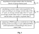
- Fig. 1 is a schematic flowchart of a heating control method according to some embodiments of the present invention. As shown in Fig. 1 , the heating control method includes steps 101 to 103.
- step 101 an average current value in a heating circuit of a power battery pack is acquired.
- the average current value refers to an average value of current sampling values over a period of time. By using calculation of an average current value, it is possible to avoid influence of instantaneous fluctuation of current on control accuracy.
- a current output value required for n th cycle is calculated according to an average current value of the n th cycle, an average current value of (n-1) th cycle, an average current value of (n-2) th cycle and a preset current value, wherein n is equal to or greater than 3.
- a Pulse width Modulation (PWM) signal is outputted to a switch device of the heating circuit according to a pre-calibrated PWM control parameter corresponding to the current output value so that a difference between an actual current value in the heating circuit and the preset current value is less than a preset threshold.
- PWM Pulse width Modulation
- switching frequency of an IGBT in a heating circuit for a power battery pack is generally in a range of 100 Hz to 1000 Hz. If frequency for the PWM signal is 1000 Hz and its duty cycle is 50%, it means that discharge process in the heating circuit takes 500 ⁇ s, and charging process take also 500 ⁇ s.
- current in the heating circuit may be sampled in real time by an Analog-to-Digital Converter (ADC) based on a 10 ⁇ s interrupt scheme, and data sampled in real-time may be uploaded to a control system through a Controller Area Network (CAN) message.
- ADC Analog-to-Digital Converter
- CAN Controller Area Network
- An average value of 50 sampled data is taken as an average current value within 500 ⁇ s for subsequent calculation to filter out influence of instantaneous fluctuation of the current on its control accuracy.
- an average current value in the n th cycle, an average current value in the (n-1) th cycle, an average current value in the (n-2) th cycle and a preset current value can be used to obtain a current output value for the n th cycle.
- a PWM signal is outputted to a switching device of the heating circuit according to a pre-calibrated PWM control parameter corresponding to the current output value so that a difference between an actual current value in the heating circuit and the preset current value is less than a preset threshold.
- the preset threshold herein is an extremely small value such that actual current value of the heating circuit is infinitely close to the preset current value.
- the heating control method of embodiments of the present invention has a higher control accuracy as compared with that in related art where current in the heating circuit is indirectly controlled by controlling IGBT's operation by way of an internal resistance of the power battery pack, and can achieve rapid heating of the battery under safety and reliability.
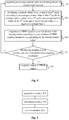
- Fig. 2 is a schematic flowchart of a heating control method according to some embodiments of the present invention.
- Fig. 2 differs from Fig. 1 in that step 102 in Fig. 1 can be subdivided into step 1021 to step 1024 in Fig 2 .
- a difference between the preset current value and the average current value of the n th cycle is set as n th cycle difference value
- a difference between the preset current value and the average current value of the (n-1) th cycle is set as (n-1) th cycle difference value
- a difference between the preset current value and the average current value of the (n-2) th cycle is set as (n-2) th cycle difference value.
- step 1022 a state of charge section of the power battery pack is acquired.
- a current increment required for the n th cycle is determined according to a pre-calibrated feedback adjustment coefficient corresponding to the state of charge section, the n th cycle difference value, (n-1) th cycle difference value and the (n-2) th cycle difference value.
- step 1024 the current output value required for the n th cycle is determined based on the current increment and the average current value of the (n-1) th cycle.
- the feedback adjustment coefficient refers to a parameter for correcting an output current based on a feedback current value (such as an average current value of the n th cycle, an average current value of the (n-1) th cycle, and an average current value of the (n-2) th cycle) in a certain operation situation.
- the feedback adjustment coefficient may include a proportional adjustment coefficient K p , an integral adjustment coefficient K i , and a differential adjustment coefficient K d .
- a feedback adjustment mode based on K p , K i , and K d is also referred to as a PID adjustment mode.
- step 1023 it may be also required to determine relationship between state of charge sections of the power battery pack and feedback adjustment coefficients before step 1023.
- state of charge of the power battery pack may be divided into a plurality of sections from high to low. Each state of charge section may be equal or unequal. Then, a value of the feedback adjustment coefficient matched with each state of charge section is determined. By doing so, it is possible to avoid influence of the state of charge of the power battery pack on current control accuracy in the heating process, and thus to improve the current control accuracy.
- value of K p is gradually increased from 0 until change rate of the average current value is greater than a first threshold determined based on a proportional adjustment coefficient, so as to determine relationship between the state of charge section and the proportional adjustment coefficient.
- value of K i is gradually increased from 0 until fluctuation magnitude of the average current value is greater than a second threshold determined based on an integral adjustment coefficient, so as to determine relationship between the state of charge section and the integral adjustment coefficient.
- value of K d is gradually increased from 0 until fluctuation magnitude of the average current value is greater than a third threshold determined based on a differential adjustment coefficient, so as to determine the relationship between the state of charge section and the differential adjustment coefficient.
- K p , K i and K d may be independent of each other, or may be combined with each other.
- calibration of K i or K d may be on a basis of calibrated K p
- calibration of K d may be on a basis of calibrated K p and K i .
- the second threshold and the third threshold may be equal or not equal, which depends on actual condition of the current in the heating circuit.
- the following example illustrates calibration process for K p , K i , and K d .
- S1 Material and total capacity of the power battery pack is determined, and State of Charge (SOC) of the power battery pack is initialized to 100%.
- SOC State of Charge
- K i and K d are set to be 0. That is, for calibration of the proportional adjustment coefficient, the value of K p value is gradually increased from 0 in the absence of integral control and differential control. It is determined whether a change rate of the average current value meets a requirement (the change rate is greater than the above-mentioned first threshold). When the change rate satisfies the requirement, increasing of the value of K p value is stopped. The value of K p at this point is decreased by 10% in order to increase capability of fault tolerance of K p .
- K i is gradually increased from 0 until fluctuation of the average current value satisfies a requirement. (the fluctuation amplitude is larger than the above-mentioned second threshold). The value of K i at this point is decreased by 10% in order to increase capability of fault tolerance of K i .
- K d is gradually increased from 0 until fluctuation of the average current value satisfies a requirement (the fluctuation amplitude is greater than the above-mentioned third threshold), increasing of the value of K d is stopped.
- the value of K d at this point is decreased by 10% in order to increase capability of fault tolerance of K d .
- S5. S2 to S4 are repeated each when the power battery pack is discharged by m% for further calibration until the power battery pack is discharged to 10%.
- K p , K i , and K d suitable for each state of charge section are calibrated, it is possible to avoid influence of the state of charge of the power battery pack on current control accuracy in the heating process, and thus to improve the current control accuracy.
- the inventor of the present application finds that under the premise that the state of charge of the power battery pack remains unchanged during the heating process of the power battery pack, it requires only a PWM signal is outputtcd at a constant period and a duty cycle to keep the output current value constant. For example, when the SOC is in a range of 80%-100% and if the PWM period is a constant value in a range of 10ms to 20ms and the duty cycle is a constant value in a range of 40% to 50%, the average output current is about a constant value within 150A-170A.
- PWM control parameter may include PWM period and duty cycle.
- a method for calibrating the PWM control parameter may include: for each state of charge section, continuously adjusting value of the PWM control parameter, and determining a value of the PWM control parameter when the average current value of the heating circuit reaches to be constant as a PWM control parameter corresponding to the current output value.
- S1 Material and total capacity of the power battery pack is determined, and State of Charge (SOC) of the power battery pack is initialized to 100%.
- SOC State of Charge
- PWM period and duty cycle are adjusted until the average current value in the heating circuit reaches a current value that is 0.8 times a maximum current limit value.
- the maximum current limit value may be varied according to the SOC value.
- S2 to S4 are repeated each when the power battery pack is discharged by m% for further calibration until the power battery pack is discharged to 10%.
- I k I k ⁇ 1 + K p e k ⁇ e k ⁇ 1 + K i e k + K d e k ⁇ 2 e k ⁇ 1 + e k ⁇ 2
- Fig. 3 is a schematic flowchart of a heating control method according to some embodiments of the present invention.
- Fig. 3 differs from Fig. 1 in that, prior to step 101 in Fig. 1 , the heating control method in Fig. 3 further includes steps 104 to 106 for describing a startup strategy of the heating control method.
- step 104 in the case that the power battery pack has a demand of being heated, power requirement for the power battery pack being heated from a temperature at the n th cycle to a target temperature is acquired.
- step 105 it is determined whether the state of charge of the power battery pack meets the power requirement. If the state of charge of the power battery pack meets the power requirement, step 101 is performed; otherwise, step 106 is performed.
- a charging prompt signal is sent to a battery management system (BMS) of the power battery pack in order to charge the power battery pack until the state of charge of the power battery pack meets the power requirement.
- BMS battery management system
- Fig. 4 is a schematic flowchart of a heating control method according to some embodiments of the present invention.
- Fig. 4 differs from Fig. 1 in that, after step 103 in Fig. 1 , the heating control method in Fig. 4 further includes step 107 and step 108 for describing a stopping strategy of the heating control method.
- step 107 it is determined whether the heating circuit satisfies any one of predetermined stopping conditions. If the heating circuit satisfies any one of the predetermined stopping conditions, step 108 is performed; otherwise, step 101 is returned.
- step 108 output of the PWM signal is stopped.
- the predetermined stopping condition may include: the average current value in the heating circuit is greater than an allowable current threshold (e.g., 80% of a fuse blown value), any cell in the power battery pack has a temperature and voltage greater than an allowable operating range, and temperature of the power battery pack reaches the target temperature.
- an allowable current threshold e.g., 80% of a fuse blown value
- the predetermined stopping condition may further include: surface temperature of the IGBT is greater than a set threshold T set .
- the predetermined stopping condition may further include: temperature and voltage of any one of the battery cells sent by the BMS is out of the required heating range or is an invalid value.
- Fig. 5 is a schematic structural diagram of a heating control device according to some embodiments of the present invention. As shown in Fig. 5 , the heating control device includes an acquisition module 501, a calculation module 502, and a control module 503.
- the acquisition module 501 is configured to obtain an average current value in a heating circuit of a power battery pack.
- the calculation module 502 is configured to calculate a current output value required for n th cycle according to an average current value of the n th cycle, an average current value of (n-1) th cycle, an average current value of (n-2) th cycle and a preset current value, n is equal to or greater than 3.
- the control module 503 is configured to output a Pulse width Modulation (PWM) signal to a switch device of the heating circuit according to a pre-calibrated PWM control parameter corresponding to the current output value so that a difference between an actual current value in the heating circuit and the preset current value is less than a preset threshold.
- PWM Pulse width Modulation
- the heating control device further includes a calibration module configured to: for each state of charge section, continuously adjust value of the PWM control parameter, and determine a value of the PWM control parameter when the average current value of the heating circuit reaches to be constant as a PWM control parameter corresponding to the current output value.
- the embodiments of the present invention further provides a heating control device comprising a memory and a processor, wherein the memory is configured to store executable program codes, and the processor is configured to read the executable program codes stored in the memory to perform the above described heating control method.
- the functional blocks shown in the block diagrams described above may be implemented as hardware, software, firmware, or a combination thereof.
- it may be, for example, an electronic circuit, an application specific integrated circuit (ASIC), suitable firmware, plug-ins, function cards, and the like.
- ASIC application specific integrated circuit
- the elements of an embodiment of the present invention are programs or code segments that are used to perform the required tasks.
- Programs or code segments may be stored on a machine-readable medium or transmitted over a transmission medium or communication link via a data signal carried in a carrier wave.
- the "machine-readable medium” may include any medium that is capable of storing or transmitting information.
- machine-readable media examples include electronic circuitry, semiconductor memory devices, ROMs, flash memory, erasable ROM (EROM), floppy disks, CD-ROMs, optical disks, hard disks, fiber optic media, radio frequency (RF) links, and the like.
- the code segments may be downloaded via a computer network such as the Internet, an intranet or the like.
Landscapes
- Engineering & Computer Science (AREA)
- General Chemical & Material Sciences (AREA)
- Manufacturing & Machinery (AREA)
- Chemical & Material Sciences (AREA)
- Chemical Kinetics & Catalysis (AREA)
- Electrochemistry (AREA)
- Physics & Mathematics (AREA)
- Algebra (AREA)
- General Physics & Mathematics (AREA)
- Mathematical Analysis (AREA)
- Mathematical Optimization (AREA)
- Pure & Applied Mathematics (AREA)
- Automation & Control Theory (AREA)
- Secondary Cells (AREA)
- Electromagnetism (AREA)
- Microelectronics & Electronic Packaging (AREA)
- Charge And Discharge Circuits For Batteries Or The Like (AREA)
Claims (12)
- Heizungssteuerverfahren, gekennzeichnet durch:Erfassen (101) eines Durchschnittsstromwerts in einem Heizkreis eines Leistungsbatteriepacks, wobei der Durchschnittsstromwert einen Durchschnittsstromwert des n-ten Zyklus, einen Durchschnittsstromwert des (n-1)-ten Zyklus und einen Durchschnittsstromwert des (n-2)-ten Zyklus umfasst, wobei n gleich oder größer als 3 ist und wobei der Zyklus eine Zeitdauer für die Stromabtastung ist;Berechnen (102) eines für den n-ten Zyklus erforderlichen Stromausgangswerts gemäß dem Durchschnittsstromwert des n-ten Zyklus, dem Durchschnittsstromwert des (n-1)-ten Zyklus, dem Durchschnittsstromwert des (n-2)-ten Zyklus und einem voreingestellten Stromwert; undAusgeben (103) eines Impulsbreitenmodulationssignals (PWM-Signal) an eine Schaltvorrichtung des Heizkreises gemäß einem vorkalibrierten PWM-Steuerparameter, wobei der vorkalibrierte PWM-Steuerparameter dem Stromausgangswert entspricht, der für den n-ten Zyklus erforderlich ist, so dass eine Differenz zwischen einem Iststromwert im Heizkreis und dem voreingestellten Stromwert kleiner als ein voreingestellter Schwellenwert ist.
- Verfahren nach Anspruch 1, wobei das Berechnen des für den n-ten Zyklus erforderlichen Stromausgangswerts gemäß dem Durchschnittsstromwert des n-ten Zyklus, dem Durchschnittsstromwert des (n-1)-ten Zyklus, dem Durchschnittsstromwert des (n-2)-ten Zyklus und dem voreingestellten Stromwert, umfasst:Einstellen (1021) einer Differenz zwischen dem voreingestellten Stromwert und dem Durchschnittsstromwert des n-ten Zyklus als Differenzwert des n-ten Zyklus, Einstellen einer Differenz zwischen dem voreingestellten Stromwert und dem Durchschnittsstromwert des (n-1)-ten Zyklus als Differenzwert des (n-1)-ten Zyklus und Einstellen einer Differenz zwischen dem voreingestellten Stromwert und dem Durchschnittsstromwert des (n-2)-ten Zyklus als Differenzwert des (n-2)-ten Zyklus;Erfassen (1022) eines Ladezustandsabschnitts des Leistungsbatteriepacks;Bestimmen (1023) eines für den n-ten Zyklus erforderlichen Strominkrements gemäß einem dem Ladungszustandsabschnitt entsprechenden vorkalibrierten Rückkopplungseinstellkoeffizienten, dem Differenzwert des n-ten Zyklus, dem Differenzwert des (n-1)-ten Zyklus und dem Differenzwert des (n-2)-ten Zyklus;Bestimmen (1024) des für den n-ten Zyklus erforderlichen Stromausgangswerts basierend auf dem Strominkrement und dem Durchschnittsstromwert des (n-1)-ten Zyklus.
- Verfahren nach Anspruch 2, wobei vor dem Bestimmen des für den n-ten Zyklus erforderlichen Strominkrements gemäß einem dem Ladungszustandsabschnitt entsprechenden vorkalibrierten Rückkopplungseinstellkoeffizienten, dem Differenzwert des n-ten Zyklus, dem Differenzwert des (n-1)-ten Zyklus und dem Differenzwert des (n-2)-ten Zyklus, das Verfahren ferner umfasst:
Bestimmen der Beziehung zwischen Ladezustandsabschnitten des Leistungsbatteriepacks und Rückkopplungseinstellkoeffizienten. - Verfahren nach Anspruch 3, wobei der Rückkopplungseinstellkoeffizient einen proportionalen Einstellkoeffizienten, einen integralen Einstellkoeffizienten und einen differentiellen Einstellkoeffizienten umfasst und das Bestimmen der Beziehung zwischen Ladezustandsabschnitten des Leistungsbatteriepacks und Rückkopplungseinstellkoeffizienten umfasst:für jeden Ladungszustandsabschnitt, der proportionale Einstellkoeffizient von 0 allmählich erhöht wird, bis die Änderungsrate des Durchschnittsstromwerts größer als ein erster Schwellenwert ist, der basierend auf einem proportionalen Einstellkoeffizienten bestimmt wird, und die Beziehung zwischen dem Ladungszustandsabschnitt und dem proportionalen Einstellkoeffizienten bestimmt wird;für jeden Ladungszustandsabschnitt, der integrale Einstellkoeffizient von 0 allmählich erhöht wird, bis die Schwankungsgröße des Durchschnittsstromwerts größer als ein zweiter Schwellenwert ist, der basierend auf einem integralen Einstellkoeffizienten bestimmt wird, und die Beziehung zwischen dem Ladungszustandsabschnitt und dem Integralen Einstellkoeffizienten bestimmt wird;für jeden Ladungszustandsabschnitt, der differentiale Einstellkoeffizient von 0 allmählich erhöht wird, bis die Schwankungsgröße des Durchschnittsstromwerts größer als ein dritter Schwellenwert ist, der basierend auf einem differentialen Einstellkoeffizienten bestimmt wird, und die Beziehung zwischen dem Ladungszustandsabschnitt und dem differentialen Einstellkoeffizienten bestimmt wird.
- Verfahren nach Anspruch 1, wobei vor dem Ausgeben des Impulsbreitenmodulationssignals (PWM-Signal) an die Schaltvorrichtung des Heizkreises gemäß dem vorkalibrierten PWM-Steuerparameter, das Verfahren ferner umfasst: für jeden Ladezustandsabschnitt,
kontinuierliches Einstellen von Wert des PWM-Steuerparameters; und
Bestimmen eines Wertes des PWM-Steuerparameters, wenn der Durchschnittsstromwert des Heizkreises als der vorkalibrierte PWM-Steuerparameter konstant wird. - Verfahren nach Anspruch 1, wobei vor dem Erfassen des Durchschnittsstromwerts in dem Heizkreis des Leistungsbatteriepacks, das Verfahren ferner umfasst:Erfassen (104), für den Fall, dass der Leistungsbatteriepack erwärmt werden muss, des Leistungsbedarfs für den Leistungsbatteriepack, der von einer Temperatur im n-ten Zyklus auf eine Zieltemperatur erwärmt wird;Bestimmen (105), ob der Ladezustand des Leistungsbatteriepacks den Leistungsbedarf erfüllt; Erhalten (101) des Durchschnittsstromwerts im Heizkreis des Leistungsbatteriepacks, wenn der Ladezustand des Leistungsbatteriepacks den Leistungsbedarf erfüllt.
- Verfahren nach Anspruch 6, wobei nach dem Bestimmen, ob der Ladezustand des Leistungsbatteriepacks den Leistungsbedarf erfüllt, das Verfahren ferner umfasst:
Senden (106) eines Ladeaufforderungssignals an ein Batteriemanagementsystem (BMS) des Leistungsbatteriepacks, wenn der Ladezustand des Leistungsbatteriepacks den Leistungsbedarf nicht erfüllt, um den Leistungsbatteriepack aufzuladen, bis der Ladezustand des Leistungsbatteriepacks den Leistungsbedarf erfüllt. - Verfahren nach Anspruch 1, wobei nach dem Ausgeben des Impulsbreitenmodulationssignals (PWM-Signal) an die Schaltvorrichtung des Heizkreises gemäß dem vorkalibrierten PWM-Steuerparameter, das Verfahren ferner umfasst:
Anhalten (108) von Ausgeben des PWM-Signals, wenn der Heizkreis eine der vorgegebenen Anhaltbedingungen erfüllt, einschließlich: der Durchschnittsstromwert im Heizkreis größer als eine zulässige Stromschwelle ist, jede Zelle im Leistungsbatteriepack eine höhere Temperatur und Spannung als einen zulässigen Betriebsbereich hat, und die Temperatur des Batteriepacks die Zieltemperatur erreicht. - Heizungssteuervorrichtung, gekennzeichnet durch:ein Erfassungsmodul, das dazu konfiguriert ist, einen Durchschnittsstromwert in einem Heizkreis eines Leistungsbatteriepacks zu erfassen, wobei der Durchschnittsstromwert einen Durchschnittsstromwert des n-ten Zyklus, einen Durchschnittsstromwert des (n-1)-ten Zyklus und einen Durchschnittsstromwert des (n-2)-ten Zyklus umfasst, wobei n gleich oder größer als 3 ist und wobei der Zyklus eine Zeitdauer für die Stromabtastung ist;ein Berechnungsmodul, das dazu konfiguriert ist, einen für den n-ten Zyklus erforderlichen Stromausgangswert gemäß dem Durchschnittsstromwert des n-ten Zyklus, dem Durchschnittsstromwert des (n-1)-ten Zyklus und dem Durchschnittsstromwert des (n-2)-ten Zyklus und einem voreingestellten Stromwert zu berechnen;ein Steuermodul, das dazu konfiguriert ist, ein PWM (Pulse Width Modulation)-Signal gemäß einem vorkalibrierten PWM-Steuerparameter an eine Schaltvorrichtung des Heizkreises auszugeben, wobei der vorkalibrierte PWM-Steuerparameter dem Stromausgangswert entspricht, der für den n-ten Zyklus erforderlich ist, so dass eine Differenz zwischen einem Iststromwert im Heizkreis und dem voreingestellten Stromwert kleiner als ein voreingestellter Schwellenwert ist.
- Heizungssteuervorrichtung nach Anspruch 9, ferner umfassend:
ein Kalibrierungsmodul, das dazu konfiguriert ist: für jeden Ladungszustandsabschnitt, den Wert des PWM-Steuerparameters kontinuierlich einzustellen und einen Wert des PWM-Steuerparameters zu bestimmen, wenn der Durchschnittsstromwert des Heizkreises als der vorkalibrierte PWM-Steuerparameter konstant wird. - Heizungssteuervorrichtung nach Anspruch 9, ferner umfassend einen Speicher und einen Prozessor,
der Speicher dazu konfiguriert ist, ausführbare Programmcodes zu speichern. und
der Prozessor dazu konfiguriert ist, die im Speicher gespeicherten ausführbaren Programmcodes zu lesen, um als Module gemäß einem der Ansprüche 9 bis 10 zu fungieren. - Computerlesbares Speichermedium, auf dem Computeranweisungen gespeichert sind, die, wenn sie von einem Prozessor ausgeführt werden, den Prozessor dazu veranlassen, Schritte des Verfahrens gemäß einem der Ansprüche 1 bis 8 zu implementieren.
Applications Claiming Priority (1)
| Application Number | Priority Date | Filing Date | Title |
|---|---|---|---|
| CN201810495990.9A CN108736108B (zh) | 2018-05-22 | 2018-05-22 | 加热控制方法和加热控制装置 |
Publications (2)
| Publication Number | Publication Date |
|---|---|
| EP3573172A1 EP3573172A1 (de) | 2019-11-27 |
| EP3573172B1 true EP3573172B1 (de) | 2020-09-23 |
Family
ID=63937787
Family Applications (1)
| Application Number | Title | Priority Date | Filing Date |
|---|---|---|---|
| EP19150225.1A Active EP3573172B1 (de) | 2018-05-22 | 2019-01-03 | Heizungsregelungsverfahren und heizungsregelungsvorrichtung |
Country Status (3)
| Country | Link |
|---|---|
| US (1) | US11309598B2 (de) |
| EP (1) | EP3573172B1 (de) |
| CN (1) | CN108736108B (de) |
Families Citing this family (27)
| Publication number | Priority date | Publication date | Assignee | Title |
|---|---|---|---|---|
| CN111216600B (zh) * | 2018-11-27 | 2024-04-16 | 中信国安盟固利动力科技有限公司 | 一种可调加热速度的电池系统及其控制方法 |
| CN111347935B (zh) * | 2018-12-21 | 2021-10-22 | 比亚迪股份有限公司 | 一种车辆及其动力电池加热装置与方法 |
| CN111354999B (zh) | 2018-12-21 | 2021-07-09 | 比亚迪股份有限公司 | 一种车辆及其动力电池加热装置与方法 |
| KR102699008B1 (ko) | 2019-08-30 | 2024-08-26 | 현대자동차주식회사 | 모터 구동 시스템을 이용한 배터리 승온 시스템 및 방법 |
| CN110850721B (zh) * | 2019-12-02 | 2023-02-07 | 合肥工业大学 | 一种电流自适应标定控制方法、系统及电子设备 |
| CN111208861B (zh) * | 2020-01-15 | 2022-01-18 | 重庆超力电器有限责任公司 | Ptc功率控制方法和装置 |
| CN111430845B (zh) * | 2020-03-20 | 2023-08-11 | 浙江吉利控股集团有限公司 | 一种电池包热管理方法、装置、存储介质及电子设备 |
| CN113016116A (zh) * | 2020-05-07 | 2021-06-22 | 深圳市大疆创新科技有限公司 | 供电电路、电源装置、移动平台和剩余电量的调节方法 |
| CN113745700B (zh) * | 2020-05-29 | 2023-08-08 | 比亚迪股份有限公司 | 电动汽车及其动力电池的加热方法、装置和存储介质 |
| KR20220026970A (ko) | 2020-08-26 | 2022-03-07 | 현대자동차주식회사 | 모터 구동 시스템을 이용한 배터리 승온 시스템 및 방법 |
| CN112151914B (zh) * | 2020-09-15 | 2022-08-09 | 欣旺达电动汽车电池有限公司 | 动力电池交流加热方法、装置和电动交通工具 |
| KR20220089347A (ko) | 2020-12-21 | 2022-06-28 | 현대자동차주식회사 | 모터 구동 시스템을 이용한 배터리 승온 시스템 및 방법 |
| KR102893180B1 (ko) * | 2021-01-28 | 2025-12-01 | 컨템포러리 엠퍼렉스 테크놀로지 (홍콩) 리미티드 | 충전 방법, 전원 배터리의 배터리 관리 시스템 및 충전 파일 |
| CN112909381B (zh) * | 2021-03-30 | 2025-06-06 | 深圳市吉毅创能源科技有限公司 | 电池加热电路、控制器及方法 |
| CN114024352B (zh) * | 2021-11-16 | 2025-08-22 | 深圳市波斯曼技术有限公司 | 一种应用于轨道交通的钠离子电池管理系统 |
| CN115078802B (zh) * | 2022-05-25 | 2026-04-28 | 一汽解放汽车有限公司 | 混合动力车的上装能量获取方法、装置和计算机设备 |
| CN114976368B (zh) * | 2022-06-30 | 2024-09-13 | 如果新能源科技(江苏)股份有限公司 | 一种电池包的加热方法、电池包和离网供电系统 |
| CN115139829B (zh) * | 2022-07-29 | 2024-06-18 | 潍柴动力股份有限公司 | 一种充电加热控制方法、装置、电子设备及存储介质 |
| CN115079750B (zh) * | 2022-08-11 | 2023-04-25 | 中国核动力研究设计院 | 焊接设备的加热控制方法、设备及计算机可读存储介质 |
| CN115267604B (zh) * | 2022-08-23 | 2025-09-05 | 兴储世纪科技(深圳)有限公司 | 一种储能电池温度调节系统检测方法 |
| CN115395618B (zh) * | 2022-09-21 | 2025-06-27 | 东集技术股份有限公司 | 一种锂电池温控方法、系统、设备和可读存储介质 |
| CN115388955A (zh) * | 2022-10-25 | 2022-11-25 | 国网浙江省电力有限公司宁波市北仑区供电公司 | 配电柜监控方法及系统 |
| CN115903948B (zh) * | 2022-11-04 | 2025-10-28 | 广州华凌制冷设备有限公司 | 功率器件的保护控制方法、装置、变频控制器及存储介质 |
| CN116036481B (zh) * | 2022-12-27 | 2026-01-06 | 广东花至美容科技有限公司 | 美容仪控制方法、存储介质及电子设备 |
| CN117080624B (zh) * | 2023-09-13 | 2024-04-05 | 苏州华骞时代新能源科技有限公司 | 一种电池加热控制方法及系统 |
| CN119325158A (zh) * | 2024-12-18 | 2025-01-17 | 深圳艾为电气技术股份有限公司 | Ptc加热器功率控制方法、装置、设备及介质 |
| CN120049579B (zh) * | 2025-04-24 | 2025-08-05 | 深圳市乌托邦创意科技有限公司 | 一种移动电源的低能量损耗使用方法及装置 |
Family Cites Families (17)
| Publication number | Priority date | Publication date | Assignee | Title |
|---|---|---|---|---|
| FI110218B (fi) | 1993-12-30 | 2002-12-13 | Fortum Oil & Gas Oy | Menetelmiä ja laitteisto sähkökemiallisten laitteiden jäähtymisen estämiseksi |
| DE19904181A1 (de) | 1999-02-03 | 2000-08-10 | Nokia Mobile Phones Ltd | Vorrichtung zum Reaktivieren einer elektrischen Batterie |
| US7382102B2 (en) * | 2005-06-13 | 2008-06-03 | Chrysler Llc | Heating of batteries using reactive power |
| CN100440614C (zh) * | 2007-01-26 | 2008-12-03 | 清华大学 | 一种实时估计镍氢动力电池内外温差的方法 |
| US8143863B2 (en) * | 2009-10-12 | 2012-03-27 | O2Micro, Inc | Circuits and methods for controlling a current flowing through a battery |
| CN102082306B (zh) * | 2010-07-30 | 2012-11-21 | 比亚迪股份有限公司 | 一种电池的加热电路 |
| KR101584405B1 (ko) * | 2013-10-31 | 2016-01-12 | 주식회사 엘지화학 | 고정 인터페이스를 구비한 응용 모듈 |
| CN105529508A (zh) * | 2014-06-30 | 2016-04-27 | 比亚迪股份有限公司 | 电池加热系统、电池装置及电动汽车 |
| EP3215862B1 (de) * | 2014-11-04 | 2021-01-06 | CPS Technology Holdings LLC | Skalierbares modulares design eines 48volt li-ionen batteriemanagementsystems |
| JP6156353B2 (ja) * | 2014-12-24 | 2017-07-05 | トヨタ自動車株式会社 | 車載電池の昇温装置および昇温方法 |
| CN107591589B (zh) * | 2016-07-08 | 2019-08-30 | 宁德时代新能源科技股份有限公司 | 电芯加热控温方法 |
| JP6684184B2 (ja) * | 2016-08-12 | 2020-04-22 | 株式会社Subaru | バッテリ加温制御装置 |
| CN106785233B (zh) * | 2016-12-27 | 2019-04-02 | 宁德时代新能源科技股份有限公司 | 电池结构的加热控制方法、加热控制装置以及电池系统 |
| CN107482259A (zh) * | 2017-05-27 | 2017-12-15 | 宝沃汽车(中国)有限公司 | 电池加热回路电流的计算方法、装置、系统及车辆 |
| CN107171041B (zh) * | 2017-06-12 | 2019-02-12 | 北京理工大学 | 一种动力电池交流电变电流梯次加热方法 |
| CN107317066B (zh) | 2017-06-30 | 2020-02-18 | 北京新能源汽车股份有限公司 | 动力电池的加热控制方法以及系统 |
| CN107910617A (zh) * | 2017-11-15 | 2018-04-13 | 西安蜂语信息科技有限公司 | 电池加热方法、装置及电池加热模组 |
-
2018
- 2018-05-22 CN CN201810495990.9A patent/CN108736108B/zh active Active
- 2018-12-27 US US16/233,096 patent/US11309598B2/en active Active
-
2019
- 2019-01-03 EP EP19150225.1A patent/EP3573172B1/de active Active
Non-Patent Citations (1)
| Title |
|---|
| None * |
Also Published As
| Publication number | Publication date |
|---|---|
| CN108736108B (zh) | 2020-03-10 |
| EP3573172A1 (de) | 2019-11-27 |
| CN108736108A (zh) | 2018-11-02 |
| US11309598B2 (en) | 2022-04-19 |
| US20190363408A1 (en) | 2019-11-28 |
Similar Documents
| Publication | Publication Date | Title |
|---|---|---|
| EP3573172B1 (de) | Heizungsregelungsverfahren und heizungsregelungsvorrichtung | |
| CN102457082B (zh) | 过量电流检测控制方法 | |
| EP3096432B1 (de) | Gerät und verfahren zur leistungssteuerung einer batterie | |
| JP4762505B2 (ja) | バッテリのウォームアップ制御装置 | |
| JP4925060B2 (ja) | 電池状態推定装置 | |
| KR100802310B1 (ko) | 배터리의 충전 또는 방전 출력 조정방법 및 장치 | |
| US10120035B2 (en) | Monitoring and control of electrochemical cell degradation via strain based battery testing | |
| US11114708B2 (en) | Battery pack temperature control method and device | |
| CN109073708B (zh) | 二次电池劣化估计装置和二次电池劣化估计方法 | |
| JP5091634B2 (ja) | 電池パック、及び充電システム | |
| US20190123571A1 (en) | Battery Controlling Device | |
| JP2013072677A (ja) | 二次電池の充電状態推定装置 | |
| EP3828565B1 (de) | Fahrzeug und steuerungsverfahren dafür | |
| JP2006174597A (ja) | ハイブリッド車のバッテリウォームアップ制御装置 | |
| CN105359329A (zh) | 用于蓄电池管理的方法和蓄电池管理系统 | |
| CN106385799B (zh) | 用于电池组管理的方法和电池组管理系统 | |
| US20220085431A1 (en) | Method and device for managing the thermal behavior of a battery | |
| JP6531501B2 (ja) | 蓄電池制御装置 | |
| JPH09308126A (ja) | 充電装置 | |
| KR101925113B1 (ko) | 복수의 배터리 유닛들을 포함하는 전지팩의 충전량을 향상시키기 위한 전지팩 충전기 | |
| JP2006174596A (ja) | ハイブリッド車のバッテリウォームアップ制御装置 | |
| US20180062215A1 (en) | Battery system and method for operating a battery system | |
| JP5454027B2 (ja) | 充電制御装置及び充電制御方法 | |
| US20230048538A1 (en) | Method for controlling a cell current limiting value for a battery management system, battery management system | |
| US12374910B2 (en) | Charging/discharging control device and charging/discharging control method |
Legal Events
| Date | Code | Title | Description |
|---|---|---|---|
| PUAI | Public reference made under article 153(3) epc to a published international application that has entered the european phase |
Free format text: ORIGINAL CODE: 0009012 |
|
| STAA | Information on the status of an ep patent application or granted ep patent |
Free format text: STATUS: THE APPLICATION HAS BEEN PUBLISHED |
|
| AK | Designated contracting states |
Kind code of ref document: A1 Designated state(s): AL AT BE BG CH CY CZ DE DK EE ES FI FR GB GR HR HU IE IS IT LI LT LU LV MC MK MT NL NO PL PT RO RS SE SI SK SM TR |
|
| AX | Request for extension of the european patent |
Extension state: BA ME |
|
| STAA | Information on the status of an ep patent application or granted ep patent |
Free format text: STATUS: REQUEST FOR EXAMINATION WAS MADE |
|
| 17P | Request for examination filed |
Effective date: 20200319 |
|
| RBV | Designated contracting states (corrected) |
Designated state(s): AL AT BE BG CH CY CZ DE DK EE ES FI FR GB GR HR HU IE IS IT LI LT LU LV MC MK MT NL NO PL PT RO RS SE SI SK SM TR |
|
| REG | Reference to a national code |
Ref country code: DE Ref legal event code: R079 Ref document number: 602019000704 Country of ref document: DE Free format text: PREVIOUS MAIN CLASS: H01M0010615000 Ipc: H05B0001020000 |
|
| GRAP | Despatch of communication of intention to grant a patent |
Free format text: ORIGINAL CODE: EPIDOSNIGR1 |
|
| STAA | Information on the status of an ep patent application or granted ep patent |
Free format text: STATUS: GRANT OF PATENT IS INTENDED |
|
| RIC1 | Information provided on ipc code assigned before grant |
Ipc: H01M 10/651 20140101ALI20200604BHEP Ipc: H05B 1/02 20060101AFI20200604BHEP Ipc: H01M 10/633 20140101ALI20200604BHEP Ipc: H01M 10/615 20140101ALI20200604BHEP |
|
| INTG | Intention to grant announced |
Effective date: 20200630 |
|
| GRAS | Grant fee paid |
Free format text: ORIGINAL CODE: EPIDOSNIGR3 |
|
| GRAA | (expected) grant |
Free format text: ORIGINAL CODE: 0009210 |
|
| STAA | Information on the status of an ep patent application or granted ep patent |
Free format text: STATUS: THE PATENT HAS BEEN GRANTED |
|
| AK | Designated contracting states |
Kind code of ref document: B1 Designated state(s): AL AT BE BG CH CY CZ DE DK EE ES FI FR GB GR HR HU IE IS IT LI LT LU LV MC MK MT NL NO PL PT RO RS SE SI SK SM TR |
|
| REG | Reference to a national code |
Ref country code: GB Ref legal event code: FG4D |
|
| REG | Reference to a national code |
Ref country code: CH Ref legal event code: EP |
|
| REG | Reference to a national code |
Ref country code: DE Ref legal event code: R096 Ref document number: 602019000704 Country of ref document: DE |
|
| REG | Reference to a national code |
Ref country code: IE Ref legal event code: FG4D |
|
| REG | Reference to a national code |
Ref country code: AT Ref legal event code: REF Ref document number: 1317739 Country of ref document: AT Kind code of ref document: T Effective date: 20201015 |
|
| PG25 | Lapsed in a contracting state [announced via postgrant information from national office to epo] |
Ref country code: GR Free format text: LAPSE BECAUSE OF FAILURE TO SUBMIT A TRANSLATION OF THE DESCRIPTION OR TO PAY THE FEE WITHIN THE PRESCRIBED TIME-LIMIT Effective date: 20201224 Ref country code: FI Free format text: LAPSE BECAUSE OF FAILURE TO SUBMIT A TRANSLATION OF THE DESCRIPTION OR TO PAY THE FEE WITHIN THE PRESCRIBED TIME-LIMIT Effective date: 20200923 Ref country code: SE Free format text: LAPSE BECAUSE OF FAILURE TO SUBMIT A TRANSLATION OF THE DESCRIPTION OR TO PAY THE FEE WITHIN THE PRESCRIBED TIME-LIMIT Effective date: 20200923 Ref country code: NO Free format text: LAPSE BECAUSE OF FAILURE TO SUBMIT A TRANSLATION OF THE DESCRIPTION OR TO PAY THE FEE WITHIN THE PRESCRIBED TIME-LIMIT Effective date: 20201223 Ref country code: HR Free format text: LAPSE BECAUSE OF FAILURE TO SUBMIT A TRANSLATION OF THE DESCRIPTION OR TO PAY THE FEE WITHIN THE PRESCRIBED TIME-LIMIT Effective date: 20200923 Ref country code: BG Free format text: LAPSE BECAUSE OF FAILURE TO SUBMIT A TRANSLATION OF THE DESCRIPTION OR TO PAY THE FEE WITHIN THE PRESCRIBED TIME-LIMIT Effective date: 20201223 |
|
| REG | Reference to a national code |
Ref country code: AT Ref legal event code: MK05 Ref document number: 1317739 Country of ref document: AT Kind code of ref document: T Effective date: 20200923 |
|
| PG25 | Lapsed in a contracting state [announced via postgrant information from national office to epo] |
Ref country code: LV Free format text: LAPSE BECAUSE OF FAILURE TO SUBMIT A TRANSLATION OF THE DESCRIPTION OR TO PAY THE FEE WITHIN THE PRESCRIBED TIME-LIMIT Effective date: 20200923 Ref country code: RS Free format text: LAPSE BECAUSE OF FAILURE TO SUBMIT A TRANSLATION OF THE DESCRIPTION OR TO PAY THE FEE WITHIN THE PRESCRIBED TIME-LIMIT Effective date: 20200923 |
|
| REG | Reference to a national code |
Ref country code: NL Ref legal event code: MP Effective date: 20200923 |
|
| REG | Reference to a national code |
Ref country code: LT Ref legal event code: MG4D |
|
| PG25 | Lapsed in a contracting state [announced via postgrant information from national office to epo] |
Ref country code: EE Free format text: LAPSE BECAUSE OF FAILURE TO SUBMIT A TRANSLATION OF THE DESCRIPTION OR TO PAY THE FEE WITHIN THE PRESCRIBED TIME-LIMIT Effective date: 20200923 Ref country code: RO Free format text: LAPSE BECAUSE OF FAILURE TO SUBMIT A TRANSLATION OF THE DESCRIPTION OR TO PAY THE FEE WITHIN THE PRESCRIBED TIME-LIMIT Effective date: 20200923 Ref country code: PT Free format text: LAPSE BECAUSE OF FAILURE TO SUBMIT A TRANSLATION OF THE DESCRIPTION OR TO PAY THE FEE WITHIN THE PRESCRIBED TIME-LIMIT Effective date: 20210125 Ref country code: CZ Free format text: LAPSE BECAUSE OF FAILURE TO SUBMIT A TRANSLATION OF THE DESCRIPTION OR TO PAY THE FEE WITHIN THE PRESCRIBED TIME-LIMIT Effective date: 20200923 Ref country code: SM Free format text: LAPSE BECAUSE OF FAILURE TO SUBMIT A TRANSLATION OF THE DESCRIPTION OR TO PAY THE FEE WITHIN THE PRESCRIBED TIME-LIMIT Effective date: 20200923 Ref country code: LT Free format text: LAPSE BECAUSE OF FAILURE TO SUBMIT A TRANSLATION OF THE DESCRIPTION OR TO PAY THE FEE WITHIN THE PRESCRIBED TIME-LIMIT Effective date: 20200923 |
|
| PG25 | Lapsed in a contracting state [announced via postgrant information from national office to epo] |
Ref country code: AL Free format text: LAPSE BECAUSE OF FAILURE TO SUBMIT A TRANSLATION OF THE DESCRIPTION OR TO PAY THE FEE WITHIN THE PRESCRIBED TIME-LIMIT Effective date: 20200923 Ref country code: AT Free format text: LAPSE BECAUSE OF FAILURE TO SUBMIT A TRANSLATION OF THE DESCRIPTION OR TO PAY THE FEE WITHIN THE PRESCRIBED TIME-LIMIT Effective date: 20200923 Ref country code: ES Free format text: LAPSE BECAUSE OF FAILURE TO SUBMIT A TRANSLATION OF THE DESCRIPTION OR TO PAY THE FEE WITHIN THE PRESCRIBED TIME-LIMIT Effective date: 20200923 Ref country code: IS Free format text: LAPSE BECAUSE OF FAILURE TO SUBMIT A TRANSLATION OF THE DESCRIPTION OR TO PAY THE FEE WITHIN THE PRESCRIBED TIME-LIMIT Effective date: 20210123 Ref country code: PL Free format text: LAPSE BECAUSE OF FAILURE TO SUBMIT A TRANSLATION OF THE DESCRIPTION OR TO PAY THE FEE WITHIN THE PRESCRIBED TIME-LIMIT Effective date: 20200923 |
|
| REG | Reference to a national code |
Ref country code: DE Ref legal event code: R097 Ref document number: 602019000704 Country of ref document: DE |
|
| PG25 | Lapsed in a contracting state [announced via postgrant information from national office to epo] |
Ref country code: SK Free format text: LAPSE BECAUSE OF FAILURE TO SUBMIT A TRANSLATION OF THE DESCRIPTION OR TO PAY THE FEE WITHIN THE PRESCRIBED TIME-LIMIT Effective date: 20200923 |
|
| PLBE | No opposition filed within time limit |
Free format text: ORIGINAL CODE: 0009261 |
|
| STAA | Information on the status of an ep patent application or granted ep patent |
Free format text: STATUS: NO OPPOSITION FILED WITHIN TIME LIMIT |
|
| PG25 | Lapsed in a contracting state [announced via postgrant information from national office to epo] |
Ref country code: MC Free format text: LAPSE BECAUSE OF FAILURE TO SUBMIT A TRANSLATION OF THE DESCRIPTION OR TO PAY THE FEE WITHIN THE PRESCRIBED TIME-LIMIT Effective date: 20200923 Ref country code: DK Free format text: LAPSE BECAUSE OF FAILURE TO SUBMIT A TRANSLATION OF THE DESCRIPTION OR TO PAY THE FEE WITHIN THE PRESCRIBED TIME-LIMIT Effective date: 20200923 |
|
| 26N | No opposition filed |
Effective date: 20210624 |
|
| PG25 | Lapsed in a contracting state [announced via postgrant information from national office to epo] |
Ref country code: LU Free format text: LAPSE BECAUSE OF NON-PAYMENT OF DUE FEES Effective date: 20210103 |
|
| REG | Reference to a national code |
Ref country code: BE Ref legal event code: MM Effective date: 20210131 |
|
| PG25 | Lapsed in a contracting state [announced via postgrant information from national office to epo] |
Ref country code: IT Free format text: LAPSE BECAUSE OF FAILURE TO SUBMIT A TRANSLATION OF THE DESCRIPTION OR TO PAY THE FEE WITHIN THE PRESCRIBED TIME-LIMIT Effective date: 20200923 |
|
| PG25 | Lapsed in a contracting state [announced via postgrant information from national office to epo] |
Ref country code: IE Free format text: LAPSE BECAUSE OF NON-PAYMENT OF DUE FEES Effective date: 20210103 |
|
| REG | Reference to a national code |
Ref country code: GB Ref legal event code: 732E Free format text: REGISTERED BETWEEN 20220407 AND 20220413 |
|
| REG | Reference to a national code |
Ref country code: DE Ref legal event code: R081 Ref document number: 602019000704 Country of ref document: DE Owner name: CONTEMPORARY AMPEREX RUNZHI SOFTWARE TECHNOLOG, CN Free format text: FORMER OWNER: CONTEMPORARY AMPEREX TECHNOLOGY CO., LIMITED, CITY FUJIAN, JIAOCHENG DISTRICT NINGDE, CN |
|
| PG25 | Lapsed in a contracting state [announced via postgrant information from national office to epo] |
Ref country code: BE Free format text: LAPSE BECAUSE OF NON-PAYMENT OF DUE FEES Effective date: 20210131 |
|
| REG | Reference to a national code |
Ref country code: CH Ref legal event code: PL |
|
| PG25 | Lapsed in a contracting state [announced via postgrant information from national office to epo] |
Ref country code: LI Free format text: LAPSE BECAUSE OF NON-PAYMENT OF DUE FEES Effective date: 20220131 Ref country code: CH Free format text: LAPSE BECAUSE OF NON-PAYMENT OF DUE FEES Effective date: 20220131 |
|
| P01 | Opt-out of the competence of the unified patent court (upc) registered |
Effective date: 20230516 |
|
| P01 | Opt-out of the competence of the unified patent court (upc) registered |
Effective date: 20230519 |
|
| PG25 | Lapsed in a contracting state [announced via postgrant information from national office to epo] |
Ref country code: NL Free format text: LAPSE BECAUSE OF NON-PAYMENT OF DUE FEES Effective date: 20200923 Ref country code: CY Free format text: LAPSE BECAUSE OF FAILURE TO SUBMIT A TRANSLATION OF THE DESCRIPTION OR TO PAY THE FEE WITHIN THE PRESCRIBED TIME-LIMIT Effective date: 20200923 |
|
| PG25 | Lapsed in a contracting state [announced via postgrant information from national office to epo] |
Ref country code: HU Free format text: LAPSE BECAUSE OF FAILURE TO SUBMIT A TRANSLATION OF THE DESCRIPTION OR TO PAY THE FEE WITHIN THE PRESCRIBED TIME-LIMIT; INVALID AB INITIO Effective date: 20190103 |
|
| PG25 | Lapsed in a contracting state [announced via postgrant information from national office to epo] |
Ref country code: SI Free format text: LAPSE BECAUSE OF FAILURE TO SUBMIT A TRANSLATION OF THE DESCRIPTION OR TO PAY THE FEE WITHIN THE PRESCRIBED TIME-LIMIT Effective date: 20200923 |
|
| PG25 | Lapsed in a contracting state [announced via postgrant information from national office to epo] |
Ref country code: MK Free format text: LAPSE BECAUSE OF FAILURE TO SUBMIT A TRANSLATION OF THE DESCRIPTION OR TO PAY THE FEE WITHIN THE PRESCRIBED TIME-LIMIT Effective date: 20200923 |
|
| PG25 | Lapsed in a contracting state [announced via postgrant information from national office to epo] |
Ref country code: TR Free format text: LAPSE BECAUSE OF FAILURE TO SUBMIT A TRANSLATION OF THE DESCRIPTION OR TO PAY THE FEE WITHIN THE PRESCRIBED TIME-LIMIT Effective date: 20200923 |
|
| PG25 | Lapsed in a contracting state [announced via postgrant information from national office to epo] |
Ref country code: MT Free format text: LAPSE BECAUSE OF FAILURE TO SUBMIT A TRANSLATION OF THE DESCRIPTION OR TO PAY THE FEE WITHIN THE PRESCRIBED TIME-LIMIT Effective date: 20200923 |
|
| PGFP | Annual fee paid to national office [announced via postgrant information from national office to epo] |
Ref country code: GB Payment date: 20251120 Year of fee payment: 8 |
|
| PGFP | Annual fee paid to national office [announced via postgrant information from national office to epo] |
Ref country code: FR Payment date: 20251124 Year of fee payment: 8 |
|
| PGFP | Annual fee paid to national office [announced via postgrant information from national office to epo] |
Ref country code: DE Payment date: 20251119 Year of fee payment: 8 |